
X365GGVX - Gas stove BERTAZZONI - Free user manual and instructions
Find the device manual for free X365GGVX BERTAZZONI in PDF.
| Product type | Built-in gas range |
| Brand | Bertazzoni |
| Model | X365GGVX |
| Dimensions (W x D x H) | 915 mm x 640 mm x 915 mm |
| Power supply | 120 V / 60 Hz, 16 A, approx. 150 W |
| Gas type | Natural gas or LPG (convertible) |
| Number of burners | 5 (1 auxiliary, 2 semi-rapid, 1 rapid, 1 dual) |
| Dual burner | Inner power 2800 BTU/h, outer 12000 BTU/h |
| Oven | Gas with convection, thermostat from 140 °C to 260 °C |
| Grill | Gas, 14500 BTU/h burner |
| Ignition | Electric and manual (with match) |
| Safety | Anti-tip device, safety thermocouples, fan failure indicator |
| Surface material | Stainless steel |
| Oven racks | 2 side racks and 1 center rack |
| Oven lighting | Accessible halogen bulb |
| Ventilation | Integrated cooling fan with failure indicator |
| Maintenance | Clean with soapy water, avoid abrasives |
| Spare parts | Complete list with codes available in the manual |
| Installation | Must be carried out by a qualified professional |
| Country of origin | Italy |
Frequently Asked Questions - X365GGVX BERTAZZONI
User questions about X365GGVX BERTAZZONI
0 question about this device. Answer the ones you know or ask your own.
Ask a new question about this device
Download the instructions for your Gas stove in PDF format for free! Find your manual X365GGVX - BERTAZZONI and take your electronic device back in hand. On this page are published all the documents necessary for the use of your device. X365GGVX by BERTAZZONI.
USER MANUAL X365GGVX BERTAZZONI
DIMENSIONS: 36” (915 mm)(W) x 253/16” (640 mm)(D) x36” (915 mm)(H)
Models X365GGVX (X36 5 00 X) [M3W0GTU4X(2 or 5)A] Models X366GGVX (X36 6 00 X) [M3Y0GTU4X(2 or 5)A] IMPORTANT - PLEASE READ AND FOLLOW
- Before beginning installation, please read these instructions completely and carefully.
-Do not remove permanently affixed labels, warnings, or plates from the product. This may void the warranty. -Please observe all local and national codes and ordinances.
-Please ensure that this product is properly grounded. - The installer should leave these instructions with the consumer who should retain for local inspector's use and for future reference.
- The electrical plug should always be accessible.
Installation must conform with local codes or in the absence of codes, the National Fuel Gas Code ANSIZ223.1-latest edition. Electrical installation must be in accordance with the National Electrical Code, ANIS/NFPA70 - latest edition and/or local codes. IN CANADA: Installation must be in accordance with the current CAN/CGA-B149.1 National Gas Installation Code or CAN/CGA-B 149.2, Propane Installation Code and/or local codes. Electrical installation must be in accordance with the current CSA C22.1 Canadian Electrical Codes Part 1 and/or local codes.
Installation of any gas-fired equipment should be made by a licensed plumber. A manual gas shut-off valve must be installed in the gas supply line ahead of the oven in the gas flow for safety and ease of service.
In Massachusetts: All gas products must be installed by a "Massachusetts" licensed plumber or gasfitter. A "T" handle type manual gas valve must be installed in the gas supply line to this appliance.
![BERTAZZONI X365GGVX - Models X365GGVX (X36 5 00 X) [M3W0GTU4X(2 or 5)A] Models X366GGVX (X36 6 00 X) [M3Y0GTU4X(2 or 5)A] IMPORTANT - PLEASE READ AND FOLLOW - 1](/content/2025/01/184850/images/4c39a9fc1032bbc64a2431cf9abea41bfe677393504a742d2d4654107440deae.jpg)
![BERTAZZONI X365GGVX - Models X365GGVX (X36 5 00 X) [M3W0GTU4X(2 or 5)A] Models X366GGVX (X36 6 00 X) [M3Y0GTU4X(2 or 5)A] IMPORTANT - PLEASE READ AND FOLLOW - 2](/content/2025/01/184850/images/d16ab1f6c7221995fba558489624ff6b7663700e14400f07926e790fd5dd235b.jpg)
Warning!
- This range can tip. Injury to persons could result.
- Install anti-tip device shipped with range.
-See Installation Instructions
IMPORTANT: SAVE FOR LOCAL ELECTRICAL INSPECTOR'S USE. READ AND SAVE THESE INSTRUCTIONS FOR FUTURE REFERENCE. OBSERVE ALL GOVERNING CODES AND ORDINANCES.
WARNING: If the information in this manual is not followed exactly, a fire or explosion may result causing property damage, personal injury or death.
Do not store or use gasoline or other flammable vapors and liquids in the vicinity of this or any other appliance.
WHAT TO DO IF YOU SMELL GAS
- Do not light any appliance.
- Do not touch any electrical switch.
- Do not use any phone in your building.
- Immediately call your gas supplier from a neighbor's phone. Follow the gas supplier's instructions.
- If you cannot reach your gas suppliers, call the fire department.
Installation and service must be performed by a qualified installer, service agency or the gas supplier.
WARNING
Read this instruction booklet before installing and using the appliance.
The manufacturer will not be responsible for any damage to property or to persons caused by incorrect installation or improper use of the appliance.
The manufacturer reserves the right to make changes to its products when considered necessary and useful, without affecting the essential safety and operating characteristics.
This appliance has been designed for non-professional, domestic use only.
Warning: do not use this appliance to heat a room.
Warning: do not place any pot or pan on the open oven door. The door is made of glass and it can break if loaded with a weight.
Warning: this appliance must be used only with base feet properly installed. See installation instruction for details.
Installation instructions
This appliance shall only be installed by an authorized person. This appliance shall be installed in accordance with the manufacturer's installation instructions, IMPORTANT: this appliance must be installed in accordance with the norms & standards of the country where it will be installed.
The installation of this appliance must conform to local codes and ordinances. In the absence of local codes, Installations must conform to American National Standards, National Fuel Gas Code ANSI Z223.1 – latest edition** or B149.1.
If local codes permit, a flexible metal appliance connection with the new AGA or CGA certified design, max. 5 feet (1,5 m) long, 12 I.D. is recommended for connecting this appliance to the gas supply line. Do not bend or damage the flexible connector when moving the appliance. The pressure regulator has 12 female pipe thread. The appropriate fitting must be determined based on the size of your gas supply line, the flexible metal connector and the shutoff valve.
The appliance, when installed, must be electrically grounded in accordance with local codes or, in the absence of local codes, with the National Electrical Code, ANSI/NFPA 70.
The appliance must be isolated from the gas supply piping system by closing its individual manual shutoff valve during any pressure testing of the gas supply piping system at test pressures equal to or less than 12 psi (3.5 kPa).
For use with a pressure regulator. The regulator supplied must be used with this appliance; it shall be properly installed in order to be accessible when appliance is installed in its final location.
The gas appliance pressure regulator must be set for the gas with which the appliance is used.
This appliance can be used with Natural Gas and LP Gas. It is shipped from the factory adjusted for use with Natural Gas: CONVERSION FIXED ORIFICES ARE LOCATED IN THE LITERATURE PACK SUPPLIED WITH THE UNIT.
A gas nozzle kit for the change of type of gas are contained inside the package together with the gas appliance installation kit and instruction booklet.
The maximum inlet gas supply pressure incoming to the gas appliance pressure regulator is 20” water column (5 kPa).
The minimum gas supply pressure for checking the regulator setting shall be at least 1 " w.c. (249 Pa) above the inlet specified manifold pressure to the appliance (this operating pressure is 4" w.c. (1.00 kPa) for Natural Gas and 11" w.c. (2.75 kPa for LP Gas).
All opening and holes in the wall and floor, back and under the appliance shall be sealed before installation of the appliance.
ATTENTION: A manual valve shall be installed in an accessible location in the gas line external to the appliance for the purpose of turning on or shutting off gas to the appliance
WARNING: Do not use aerosol sprays in the vicinity of this appliance while it is in operation
Requirements
Room ventilation - Location and venting.
ATTENTION: An exhaust fan may be used with the appliance; in each case it shall be installed in conformity with the appropriate national and local standards.
ATTENTION: Exhaust hood operation may affect other vented appliances; in each case it shall be installed in conformity with the appropriate national and local standards.
INSTALLATION MANUAL
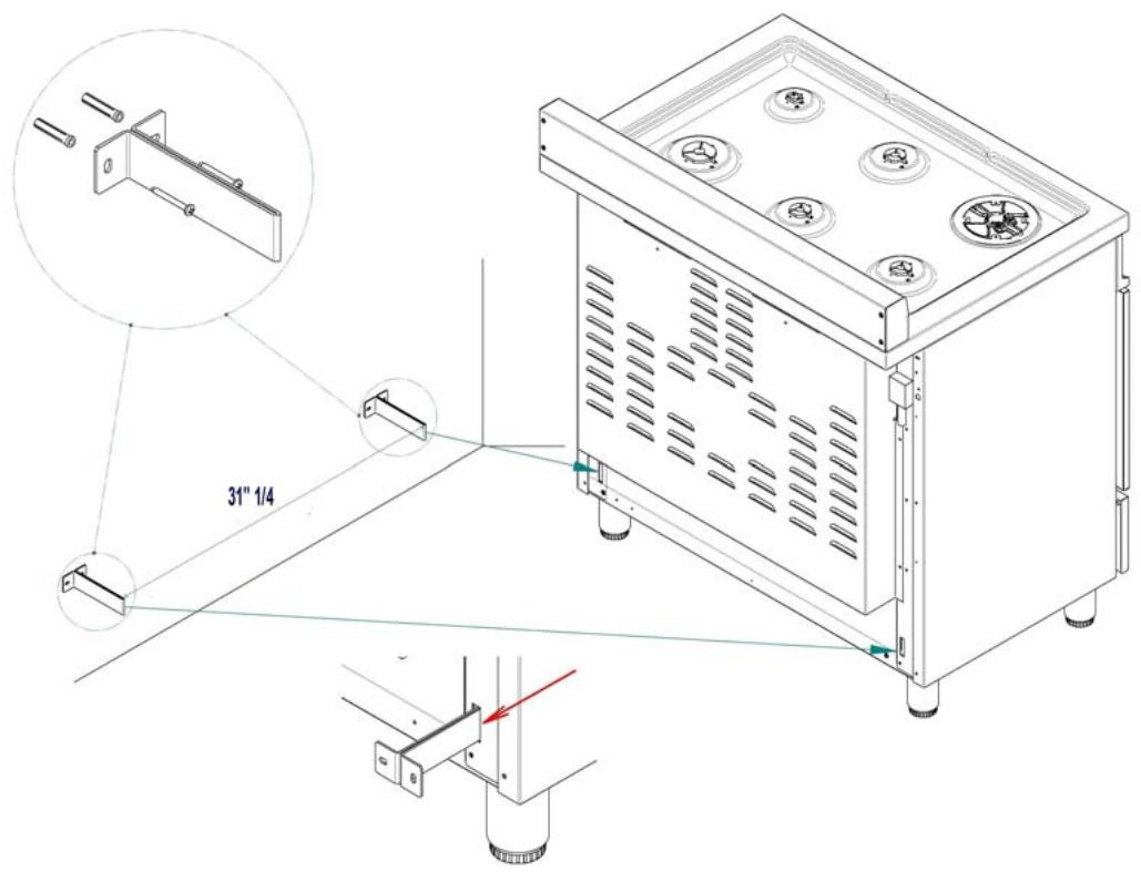
ANTI-TIP STABILITY DEVICE INSTALLATION INSTRUCTIONS
- The anti-tip bracket have to be installed to the rear wall as shown. The height for the bracket location from the floor has to be determined after the range legs have been adjusted to the proper installation height - as shown in the installation instructions - and after the range has been leveled.
- Measure from the floor to the bottom of the anti-tip bracket location on the back of the range.
- Position the two anti-tip brackets on the wall at the measured dimension plus 1/8 (0.32 cm). The brackets have to be placed at 2"5/16 (6,0 cm) from the side of the range. The distance between the two bracket is 31"1/4 (79,3 cm) clearance. Secure with suitable inserts.
- Slide the range against the wall until the brackets are fully inserted into the holes on the backside of the range..
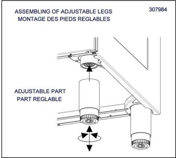
Height adjustable legs:
- Legs are packed in the top box.
- Legs should be installed with the appliance being near the location of final installation, they are not secure for long transport. After unpacking the range, raise it about a foot to insert the legs in their bases assembled on the lower part of the cooker and lower the range gently to keep any undue strain from legs and mounting hardware. It is recommended to use a pallet or lift jack instead of tilting the unit.
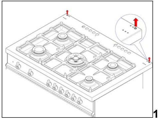
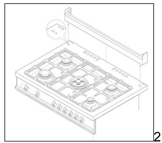
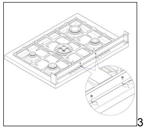
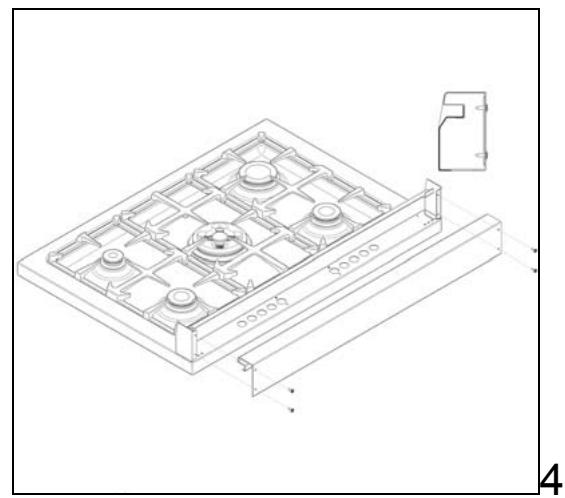
BACKGUARD INSTALLATION INSTRUCTION
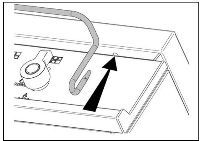
1) Remove n^2 screws fixing worktop as shown in fig.1
2) Place front part of the backguard and attach it from bottom side with the two removed screws (point 2) as shown in fig .2
3) Fix the front part of the backguard with the screws supplied with the backguard kit (fig.3)
4) Assemble back part with front part of the backguard and fix them with a screws supplied with the backguard kit (fig.4)
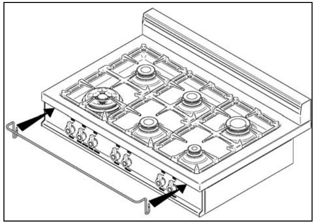
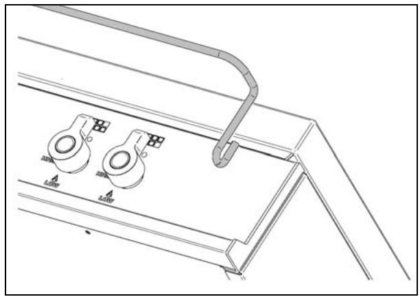
WORKTOP FRONTGUARD INSTALLATION INSTRUCTIONS
In order to increase the clearance between front edge of the worktop and the burners for your safety it is recommended to install the worktop frontguard supplied with the appliance. For installation instructions follow the instructions indicated in the following figures
INSTALLATION SIDE-BY-SIDE TO KITCHEN CABINET
- This range may be installed directly adjacent to existing 36'' (91.5 cm) high cabinets. IMPORTANT: The top border of the worktop should be at the same level of the adjacent cabinet countertop. This can be accomplished by raising the unit using the adjustment spindles on the legs.
- The range CANNOT be installed directly adjacent to sidewalls, tall cabinets, tall appliances, or other vertical surfaces above 36^ (91.4 cm) high. There must be a minimum of 6" (15.2 cm) side clearance.
- Within the side clearance to combustible vertical surfaces above 36" (91.5 cm), the maximum wall cabinet depth must be 13" (33.0 cm) and wall cabinets within this side clearance must be 18" (45.7 cm) above the 36" (91.4 cm) high countertop.
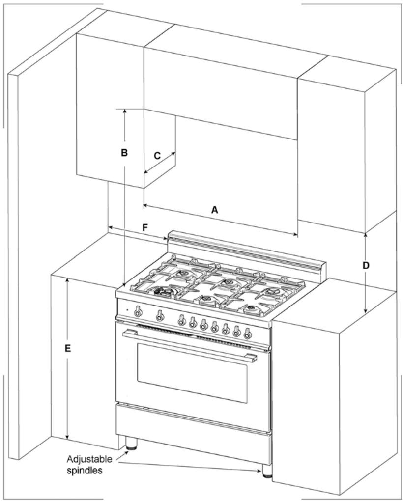
| A | 36” (91,5 cm) |
| B | 36” (91,5 cm) |
| C | 13” (33,0 cm) |
| D | 18” (45,7 cm) |
| E | 36” (91,5 cm) |
| F | 6” (15,2 cm) |
COOKER HOOD INSTALLATION
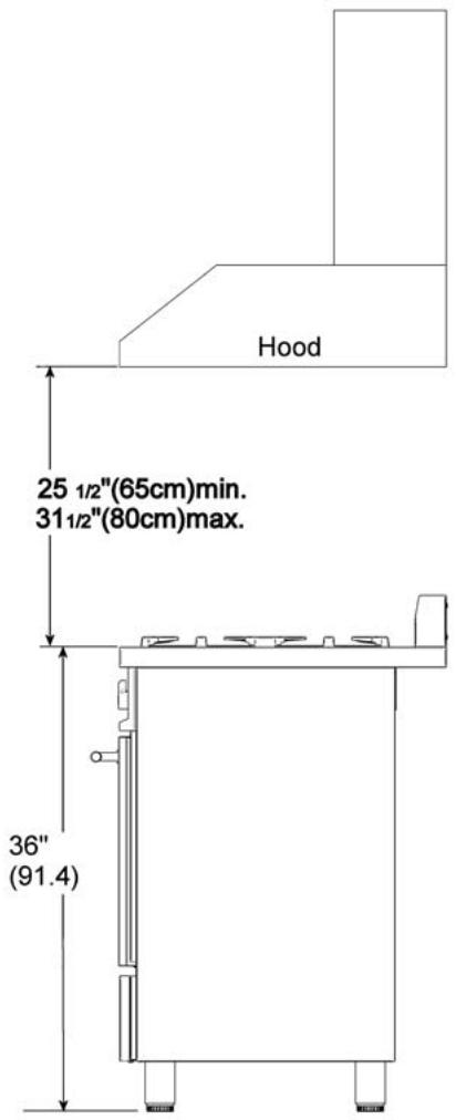
The bottom of the hood should be 25 12'' (65 cm) min. to 31 12'' (80 cm) above the countertop. This would typically result in the bottom of the hood being 61 12'' (156.2 cm) to 67 12'' (171.5 cm) above the floor. Check for other minimum clearance requirements mandated by specific local or regional installation codes. Refer to the rangehood installation instructions for additional information. These dimensions provide for safe and efficient operation of the hood.
ELECTRICAL CONNECTION
This unit is manufactured for a polarized, grounded 120 volt/60 Hz, 16 amp system. Electric power consumption is about 150 W. The minimum of 102 VAC is required for proper operation of gas ignition systems. This circuit must be grounded and properly polarized. The unit is equipped with a SJT power cord. In case of replacement, the cable shall be replaced with one of the same type, size and length.
WARNING
In case of a cooling fan failure the frontal red indicator "Fan Failure" will light up. If this happens, please turn off the appliance immediately, call the nearest after sale assistance service center and do not use the appliance until the cooling fan system of the appliance has been properly repaired by a qualified technician.
WARNING
Electrical Grounding Instructions
This appliance is equipped with a three-prong plug for your protection against shock hazard and should be plugged directly into a properly grounded socket. Do not cut or remove the grounding prong from this plug.
WARNING
ELECTRICAL SHOCK HAZARD
- Disconnect electrical power at the circuit breaker box or fuse box before installing the gas cooker
Electrically ground gas cooker - Use copper conductors only. Failure to follow these instructions could result in serious injury or death
CAUTION: label all wires prior to disconnection when servicing controls. Wiring errors can cause improper and dangerous operation.
Verify proper operation after servicing.
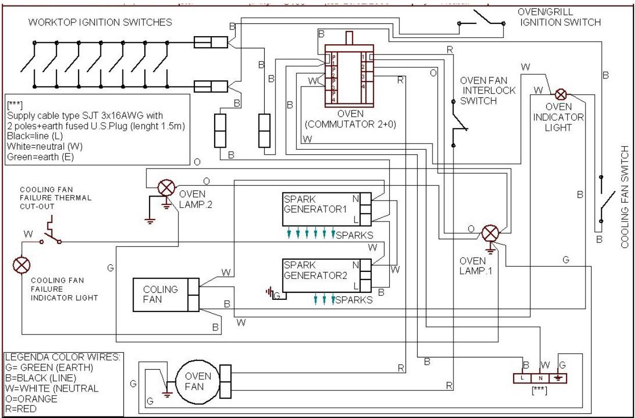
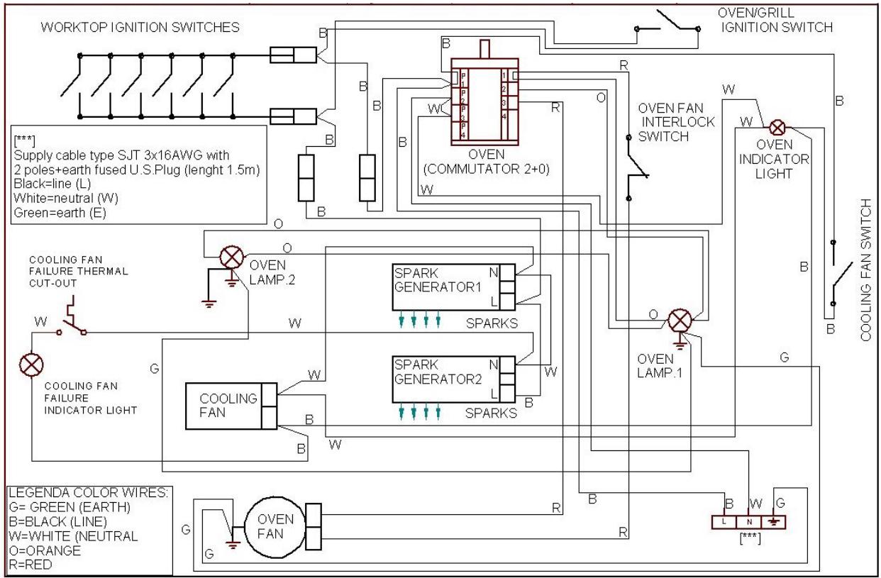
For freestanding gas range model X365GGVX (X36 500 X) M3W0GTU4X(2 or 5)A CAUTION: label all wires prior to disconnection when servicing controls. Wiring errors can cause improper and dangerous operation. Verify proper operation after servicing.
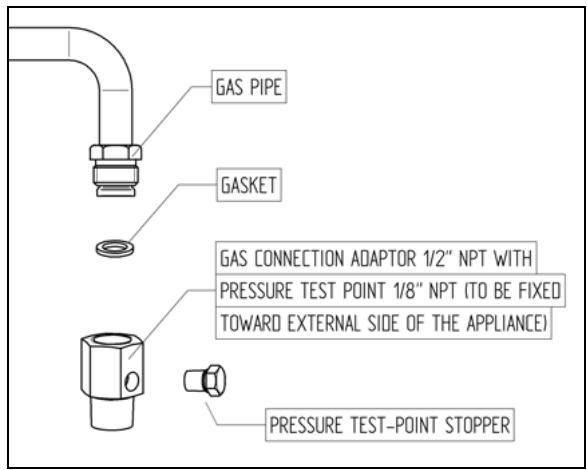
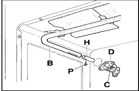
GAS CONNECTION
All gas connections must be made according to national and local codes. The gas supply (service) line must be the same size or greater than the inlet line of the appliance. This range uses a 1/2" NPT inlet (see fig. in this chapter for details of gas connections installations). On all pipe joints use sealant resistant to LP gas.
1. Manual Shut-off Valve:
This installer-supplied valve must be installed in the gas service line ahead of the appliance in the gas flow and in a position where it can be reached quickly in the event of an emergency. The manual shut-off valve shall be installed properly in order to be accessible when the appliance is installed. In Massachusetts: A 'T' handle type manual gas valve must be installed in the gas supply line to this appliance.
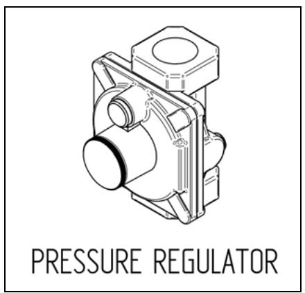
2. Pressure Regulator(see fig. in this chapter)
a) All cooking equipment must have a pressure regulator on the incoming service line for safe and efficient operation, since service pressure may fluctuate with local demand. The pressure regulator is supplied separately with the appliance; regulator has two female threads 12 NPT; it shall be installed properly in order to be accessible when appliance is installed in final position.
b) Any conversion required must be performed by your dealer or a qualified licensed plumber or gas service company. Please provide the service person with this manual before work is started on the range. (Gas conversions are the responsibility of the dealer or end user.)
c) This range can be used with Natural or LP/Propane gas. It is shipped from the factory adjusted for use with natural gas.
d) Manifold pressure should be checked with a manometer, natural gas requires 4.0" W.c.P. and LP/Propane requires 11.0" W.C.P. Incoming line pressure upstream from the regulator must be 1" W.c.P. higher than the manifold pressure in order to check the regulator. The regulator used on this range can withstand a maximum input pressure of 1/2 PSI (14.0" W.c.P.) If the line pressure is in excess of that amount, a step-down regulator will be required.
e) The appliance, its individual shut-off valve, and pressure regulator must be disconnected from the gas supply piping system during any pressure testing of that system at pressures in excess of 1/2 psig (3.45 kPa).
f) The appliance must be isolated from the gas supply piping system by closing its individual manual shut-off valve during any pressure testing of the gas supply piping system at test pressures equal to or less than 1/2 psig (3.45 kPa).
3. Flexible Connections:
a) If the unit is to be installed with flexible couplings and/or quick disconnect fittings, the installer must use a heavy-duty, AGA design-certified commercialia flexible connector of at least 1/2 (1.3 cm) ID NPT (with suitable strain reliefs) in compliance with ANSI Z21.41 and Z21.69 standards.
b) In Massachusetts: The unit must be installed with a 36" (3-foot) long flexible gas connector.
c) In Canada: CAN 1-6.10-88 metal connectors for gas appliances and CAN 1-6.9 M79 quick disconnect device for use with gas fuel.
CAUTION: Leak testing of the appliance shall be conducted according to the manufacturer's instructions. Before placing the oven into operation, always check for leaks with a soapy water solution or other acceptable method. DO NOT USE AN OPEN FLAME TO CHECK FOR LEAKS!
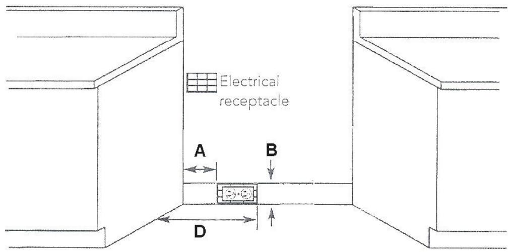
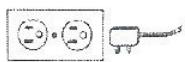
*NOTE: Ground plug and electrical wire toward the direction of the electrical outlet.
A properly-grounded horizontally- mounted electrical receptacle should be installed no higher than 3" (7.6 cm) above the floor, no less than 2" (5 cm) and no more than 8" (20,3 cm) from the right side (facing product). Check all local code requirements.
An agency-approved, properly-sized manual shut-off valve should be installed no higher than 3" (7.6 cm) above the floor
and no less than 2'' (5 cm) and no more than 8'' (20,3 cm) from the left side (facing product). To connect gas between shut-off valve and regulator, use agency-approved, properly sized flexible or rigid pipe. Check all local code requirements.
PERFORMANCE CHECKLIST
All burners are tested before leaving the factory. There are no adjustments for the burners if connected according to the information on the rating plate. Check each burner for proper operations. Flames should be blue in all settings. If service is required, contact your dealer for the name of their authorized service agency. Gas conversions and initial installation are not the responsibility of the manufacturer.
The installer should carry out the following performance checks. Refer to instructions below.
- Check surface burner ignition.
- Check air shutter adjustment (only for oven and broiler burner)- sharp blue flame, no yellow tipping, sooting or flame lifting
- Check low flame adjustment
- Check broiler and oven ignition - all burner ports.
- Check for gas leaks (odors) at all gas connections.
- Check oven bake and convection bake function.
FINAL PREPARATION
- Some stainless steel parts may have a plastic protective wrap which must be removed. The interior of the oven should be washed thoroughly with hot soapy water to remove film residues and any installation dust or debris before using it for food preparation, then rinsed and wiped dry. Solutions stronger than soap and water are rarely needed.
- All stainless steel body parts should be wiped with hot, soapy water and with a liquid cleaner recommended for use with stainless steel If buildup occurs, do not use steel wool, abrasive cloths, cleaners, or powders! If it is necessary to scrape stainless steel to remove encrusted materials, soak with hot, wet cloths to loosen the material, then use a wood or nylon scraper. Do not use a metal knife, spatula, or any other metal tool to scrape stainless steel! Scratches are almost impossible to remove.
NOTE: These installation instructions should remain with the unit for future reference. The electrical diagram is located in the backside or the appliance.
REPLACEMENT PARTS
Only authorized replacement parts may be used in performing service on the appliance. Replacement parts are available from factory authorized parts distributors.
Conversion to different types of gas
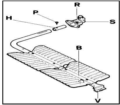
Before carrying out any maintenance work, disconnect the appliance from the gas and electric supply. For Natural Gas fit regulator assembly described in Fig.
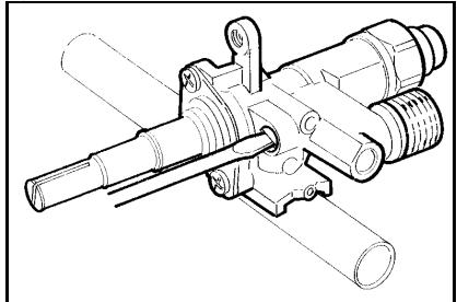
Adaptation of the pressure regulator for use with different type of gas
The pressure regulator supplied with the appliance is a convertible type pressure regulator for use with Natural Gas at a nominal outlet pressure of 4" w.c. or LP gas at a nominal outlet pressure of 11" w.c. and it is pre-arranged from the factory to operate with one of these gas/pressure as indicated in the labels affixed on the appliance, package and Instruction booklet.
To convert the regulator for use with other types of gas follow these instructions:
1) Unscrew by hand the upper metal stopper of the regulator.
2) Unscrew by hand the white plastic piece screwed under the above mentioned metal stopper, afterward screw it again in opposite way under the metal stopper (for gas reference see the written "LP" and "NAT" with relative indicating arrows on the white piece).
3) Screw again by hand the metal stopper in the original position on the regulator.
Following these exact instructions the gas regulator is converted for use with the other gas/pressure.
- CHANGING THE NOZZLES FOR USE WITH OTHER TYPES OF GAS:
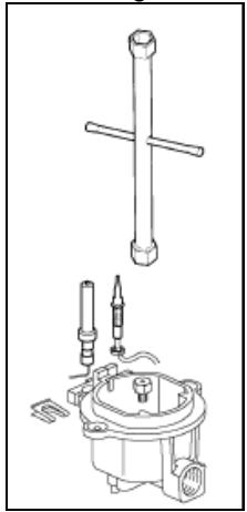
To change the nozzles of the burners use the following procedure:
Lift up the burners and unscrew the nozzles ( Fig.) using an adjustable spanner of 7mm and change the nozzles with those designed for the new gas supply according to the information given in TABLE shown below.
Follow the instructions below to change the oven burner nozzle:
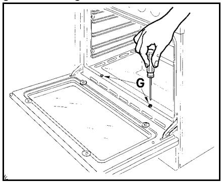
1) Remove the oven level (Fig. 9A-9B).
2) Loosen the screw V and pull out the burner from the support being careful not to damage the ignition plug and the thermocouple (Fig. 10-11).
3) Unscrew the nozzle R (Fig. 10-11) using a 10mm spanner and replace it with the nozzle needed for the new type of gas according to what is indicated in TABLE shown below.
Follow the instructions below to change the broiler burner nozzle:
1) Loosen the screw and pull out the burner from the support being careful not to damage the ignition plug and the thermocouple (Fig. 12).
2) Unscrew the nozzle C (Fig. 12) using a 7mm spanner and replace it with the nozzle needed for the new type of gas according to what is indicated in TABLE shown below.
Models X366GGVX (X36 6 00 X) [M3Y0GTU4X(2 or 5)A]
Adapting to different types of gas
| Burner | Position | Injector | Gas | Pressure | Max Rate | Min Rate | By-pass | ||
| diam. [mm.] | Type | [i.w.c.] | [BTU/h] | [W] | [BTU/h] | [W] | diam. [mm] | ||
| Auxiliary | Front R | 0,90 | NG | 4" | 3400 | 996 | 900 | 264 | Regulated |
| 0,54 | LP (Propane) | 11" | 3400 | 996 | 900 | 264 | 0,29 | ||
| Semi-Rapid | Rear L & C | 1,18 | NG | 4" | 6100 | 1787 | 1500 | 439 | Regulated |
| Front C | 0,70 | LP (Propane) | 11" | 6100 | 1787 | 1500 | 439 | 0,36 | |
| Rapid | Rear L | 1,55 | NG | 4" | 10400 | 3047 | 2500 | 732 | Regulated |
| 0,92 | LP (Propane) | 11" | 10400 | 3047 | 2500 | 732 | 0,47 | ||
| Dual Burner | Front L Inner | 0,80 | NG | 4" | 2800 | 820 | 900 | 264 | Regulated |
| 0,49 | LP (Propane) | 11" | 2800 | 820 | 900 | 264 | 0,29 | ||
| Front L Outer | N°2 x 1,15 | NG | 4" | 12000 | 3516 | 4500 | 1318 | Regulated | |
| N°2 x 0,70 | LP (Propane) | 11" | 12000 | 3516 | 4500 | 1318 | 0,65 | ||
| Oven | Ovendownside | 2,00 | NG | 4" | 16000 | 4688 | 4000 | 1172 | Regulated |
| 1,15 | LP (Propane) | 11" | 16000 | 4688 | 4000 | 1172 | 0,60 | ||
| Broiler | Ovenupside | 1,90 | NG | 4" | 14500 | 4248 | Only Max | Only Max | No by-pass |
| 1,10 | LP (Propane) | 11" | 14500 | 4248 | Only Max | Only Max | No by-pass | ||
Models X365GGVX (X36 5 00 X) [M3W0GTU4X(2 or 5)A]
Adapting to different types of gas
| Burner | Position | Injector | Gas | Pressure | Max Rate | Min Rate | By-pass diam. [mm] | ||
| diam. [mm.] | Type | [i.w.c.] | [BTU/h] | [W] | [BTU/h] | [W] | |||
| Auxiliary | Front R | 0,90 | NG | 4" | 3400 | 996 | 900 | 264 | Regulated |
| 0,54 | LP (Propane) | 11" | 3400 | 996 | 900 | 264 | 0,29 | ||
| Semi-Rapid | Rear L and R | 1,18 | NG | 4" | 6100 | 1787 | 1500 | 439 | Regulated |
| 0,70 | LP (Propane) | 11" | 6100 | 1787 | 1500 | 439 | 0,36 | ||
| Rapid | Rear L | 1,55 | NG | 4" | 10400 | 3047 | 2500 | 732 | Regulated |
| 0,92 | LP (Propane) | 11" | 10400 | 3047 | 2500 | 732 | 0,47 | ||
| Dual Burner | Centre Inner | 0,80 | NG | 4" | 2800 | 820 | 900 | 264 | Regulated |
| 0,49 | LP (Propane) | 11" | 2800 | 820 | 900 | 264 | 0,29 | ||
| Centre Outer | N°2 x 1,15 | NG | 4" | 12000 | 3516 | 4500 | 1318 | Regulated | |
| N°2 x 0,70 | LP (Propane) | 11" | 12000 | 3516 | 4500 | 1318 | 0,65 | ||
| Oven | Ovendownside | 2,00 | NG | 4" | 16000 | 4688 | 4000 | 1172 | Regulated |
| 1,15 | LP (Propane) | 11" | 16000 | 4688 | 4000 | 1172 | 0,60 | ||
| Broiler | Ovenupside | 1,90 | NG | 4" | 14500 | 4248 | Only Max | Only Max | No by-pass |
| 1,10 | LP (Propane) | 11" | 14500 | 4248 | Only Max | Only Max | No by-pass | ||
CAUTION: save the orifices removed from the appliance for future use
REGULATION OF BURNERS
Primary air adjustment:
Oven burner adjustment: follow the instructions below to adjust the primary air for the over burner:
1) Remove the oven bottom.
2) Loosen the screw P and adjust the position X of the Venturi cone (Fig. 13) according to the measurements indicated in table 4.
Broiler burner adjustment: to adjust the broiler burner loosen screw P and adjust the position X of the Venturi cone (Fig. 14) according to the measurements indicated in table 4.
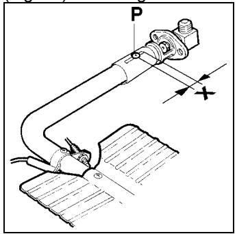
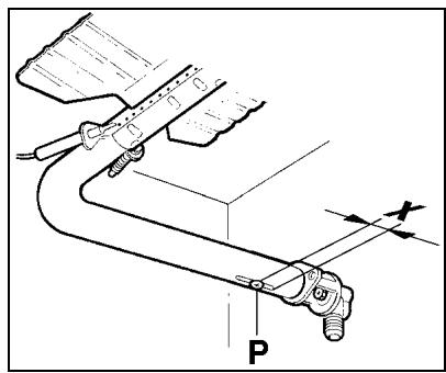
TABLE N°4: Burner primary air regulation (indicative)
| Burner | ||
| Type of gas | Oven | Broiler |
| Inches (mm) | Inches (mm) | |
| NG (Natural Gas) | 9/16 (15) | fully open |
| LP (Propane Gas) | fully open | fully open |
Work surface burner adjustment: follow the instructions below to adjust the work surface burner minimum:
1) Light the burner and set the knob to the MINIMUM position (small flame).
2) Remove the knob of the valve that is press fit on the rod of that valve.
3) The cooker is equipped with safety valves, use a small slotted screwdriver the choke valve located on the valve body and turn the choke screw to the right or left until the burner flame is adjusted to minimum
4) Make sure that the flame does not go out when switching quickly from the MAXIMUM to the MINIMUM position.
Oven burner adjustment: follow the instructions below to adjust the minimum:
1) Light the burner setting the knob to the MAXIMUM position.
2) Close the oven door and operate the oven for at least 10 minutes.
3) Set the knob to the MINIMUM position (corresponding to 250^ / 120^ ) and then remove it.
4) With a slotted screwdriver turn the choking screw (by-pass screw at the left side of the thermostat bar) and, while observing the flame at the same time through the cooker porthole, evaluate the consistency of the flame so it remains on when switching quickly from the MINIMUM to the MAXIMUM position.
WARNING: The above-mentioned adjustment should be made only for natural gas, while for operation with liquid gas the screw must be locked at the end in a clockwise direction. The broiler burner always operates at maximum and therefore no minimum adjustment is required.
SERVICE & MAINTENANCE INSTRUCTIONS
Service and maintenance only to be carried out by an authorised person
To replace parts such as burners, valves and electric components, the appliance must be open removing the worktop.
Note: if the valves must be replaced, first disassemble the ignitions switches wires.
It is recommended to replace the valve gaskets each time the valve is replaced, thus ensuring a perfect seal between the body and the gas train.
WARNING: After first installation of the appliance or after any service intervention concerning main gas parts of the appliance, make the leak test using water with soap on the gas connections in order to verify the correct installation. Do not use fire for gas leak testing.
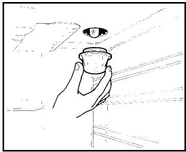
To replace the oven bulb, just unscrew the protection cap that projects out inside the oven. (Fig.19) WARNING: Disconnect power before servicing unit.
In order to remove the oven door make sure to block the hinges with a screw driver.
Call an autorised service person for this operation that can be dangerous
USER MANUAL
WARNING:
Keeping appliance area clear and free from combustible materials, gasoline and other flammable vapors and liquid.
Do not store dangerous or flammable material in the cabinet areas above appliance; store them in a safe place in order to avoid potential hazards.
For safe use of appliance, do not use it for space heating.
Do not use aerosol sprays in the vicinity of this appliance while it is in operation
Do not use oven doors as support or for sit-down.
Do not use oven cavity as storage compartment.
DESCRIPTIONS
DESCRIPTEV CAPTION FOR HOB
- Small Burner
- Medium burner
- Rapid burner
- Dual burner
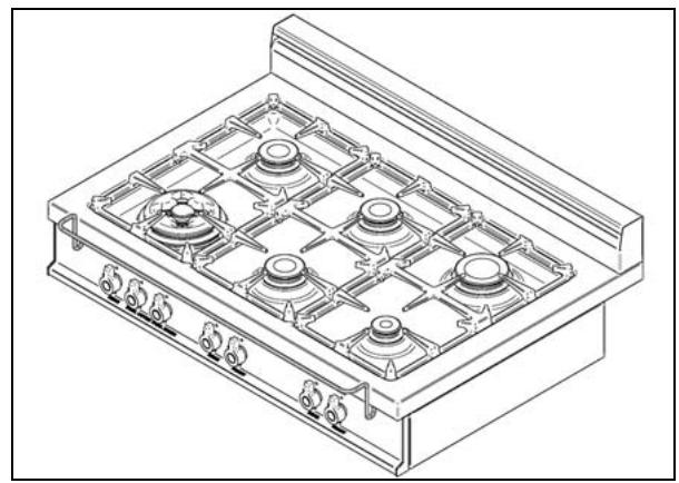
DESCRIPTION OF HOBS
Model X365GGVX (X36 500 X) [M3W0GTU4X(2 or 5)A]Fig. A
Model X366GGVX (X36 6 00 X) [M3Y0GTU4X(2 or 5)AJFig. B
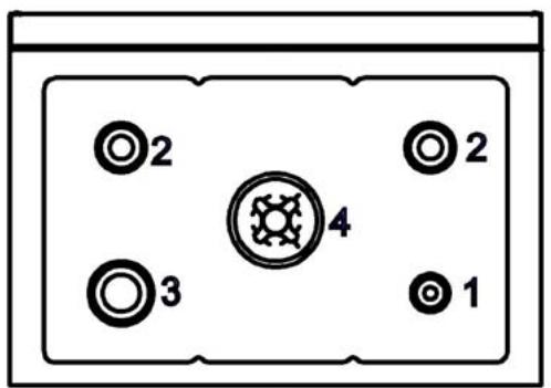
fig.A
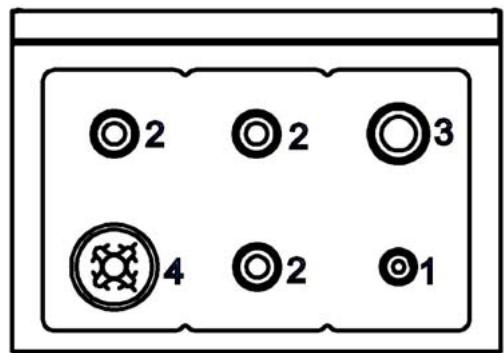
fig.B
CONTROL PANEL DESCRIPTION
On the control panel, small symbols show the function of each knob or key. Here as follows are the several controls that a cooker can have:
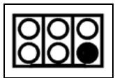
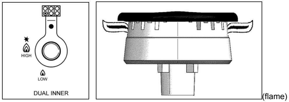
the symbol shows the disposition of burners on the worktop, the full dot identifies the burner in object (in this case the front burner on the right).
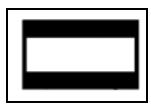
the symbol
shows the running of oven or broiler
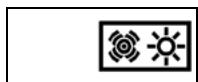
the symbol
CONVECTION
shows the swith for the oven fan and oven light

the symbol
LIGHT shows the swigth for the oven light
USING BURNERS
A diagram is etched on the control panel above each knob which indicates which burner corresponds to that knob.
Manual ignition:
Manual ignition is always possible even when the power is cut off or in the event of prolonged power failure.
Turn the knob that corresponds to the burner selected counterclockwise to the MAXIMUM position at the etched star (large flame) and place a lit match up to the burner.
Automatic electric ignition:
Turn the knob that corresponds to the burner selected anticlockwise direction to the MAXIMUM position at the etched star (large flame) and then press the knob down to activate the spark ignition. Once ignited, keep pressing the knob for about 10 seconds to allow the flame to heat the thermocouple. If the burner does not remain alight after releasing the knob repeat the above procedure,
Note: It is recommended not to try to ignite the burner if the relative flame cap is not in the correct position
Note: Dual burner is composed by two burner (inside and outside); each one operates under the relative gas valve independently from the other one.
Tips for using burners correctly:
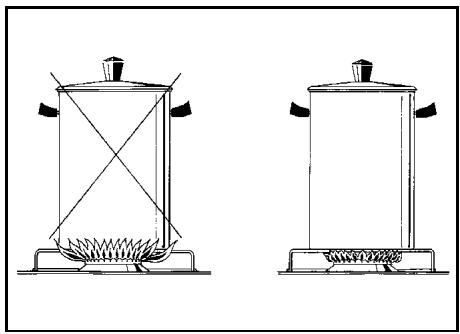
WARNING: During use of each gas burner(s) adjust the burner flame size properly so it does not extend beyond the edge of the cooking utensil. This is an instruction based on safety considerations
- Use suitable pots for each burner (see Fig. and Table )
- When the liquid is boiling, turn down the knob to the MINIMUM position.
- Always use pots with a cover.
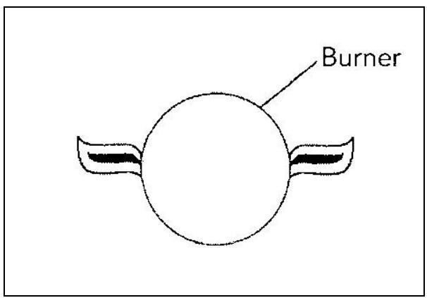
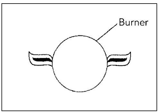
Correct flame aspect: verify that aspect flame of the worktop burners be completely blue and with an aspect as indicated in figure(flame)
Table
| Burner | Recommended pan diameters inches (mm) |
| Small | 35½"-551/8"(90 – 140) |
| Medium | 551/8"- 1023/8"(140 – 260) |
| Large | 707/8"- 1023/8" (180 – 260) |
| Dual burner | 862/3"-1023/8" (220 – 260) |
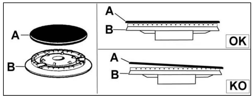
WARNING: check the position of the burner caps before operation.
Correct usage of pans:
- Dry the bottom of the pan before placing it on the hotplate.
- Use pots with a flat, thick bottom, except for wok cooking.
- When using the burners, ensure that the handles of the pans are correctly positioned. Keep children away from the appliance.
- When cooking foods with oil and fat, which are very flammable, the user should not leave the appliance unattended.
WOK PAN: To use the wok pan, please utilize a suitable wok adaptor grid; wok pan external diameter shall not be less than 10^ (25cm) and not more than 16"(40cm).
WARNING: If the power is cut off, the burners can be lit with matches.
The burners equipped with a safety thermocouple can only be lit when the knob is in the MAXIMUM position (large flame etching).
USING THE GAS OVEN
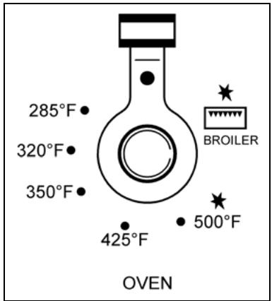
All the gas oven cookers are equipped with a thermostat and safety device to adjust the cooking temperature. The oven temperature is set by turning the knob counterclockwise to match the indicator with the temperature selected. The gas oven is combined with a gas broiler. See the specific pages for use information.
WARNING: If the burner flames are extinguished accidentally, turn off the control knob and do not try to relight the oven until after at least 1 minute.
TABLE N°7
| THERMOSTAT SETTING | TEMPERATURE °F | TEMPERATURE °C |
| MIN. | 285 | 140 |
| MED-LOW | 320 | 160 |
| MED. | 350 | 175 |
| MED-HI | 425 | 220 |
| MAX. | 500 | 260 |
The oven burner can be ignited in different ways:
- Manual lighting (it is always possible even when the power is cut off):
To light the oven, open the oven door and turn the knob at maximum position. At the same time put a lit match next to the ignition tube that is visible on the oven level. Then press the thermostat knob (this makes the gas start to flow) and keep it pressed, after the burner has been completely lit, for 10 seconds. Release the knob and make sure that the burner remains on, otherwise repeat the operation.
- Electric ignition
In this case, first open the oven door, then turn the knob to the maximum temperature setting. Then press the thermostat knob to start the gas flow and the ignition spark. Wait about 10 seconds after the burner has been completely lit and then release the knob. Make sure that the burner remains on, otherwise repeat the operation.
The ignition device should not be used for more than 15 seconds. If after that period the burner still has not been lit, do not use the device and open the door of the room or wait at least 60 seconds before trying to light the oven again.
WARNING: when trying to light the oven, the door must always be open.
The gas oven operation is indicated by a blue light
Verify that aspect flame of the oven burner be completely blue and with an aspect as indicated in figure
NOTICE: when using the oven for the first time it should be operated for 15-30 minutes at a temperature of about 500^ / 260^ without cooking anything inside in order to eliminate any moisture and odours from the internal insulation.
During normal oven use, after lighting the burner and setting the desired temperature, wait about 15 minutes before putting in any food to preheat the oven.
The oven is equipped with 4 guides at different heights level which can be used to insert shelves or the tray. To keep the oven as clean as possible it is recommended to cook meat on the tray or on the shelf that has been inserted inside the tray. The table below lists the general cooking times and the position of the tray for different types of foods. Personal experience will help to determine any variations in the values reported in the table. In any case, it is recommended to follow the instructions of the specific recipe being used.
This type of oven is equipped with a fan. The fan convection creates forced-air circulation in the horizontal direction. Thanks to this type of operation, the ventilated oven can be used for different types of cooking at the same time, without changing the taste of each food. Hot-air circulation guarantees a uniform distribution of heat. Pre-heating the oven is not necessary, but for very delicate pastries, it is recommended to heat the oven before inserting the trays.
The convection system partially changes the various notions about traditional cooking. Meat no longer needs to be turned while it is cooking and the rotisserie is no longer needed to cook a roast on the spit. Just put the meat directly on the shelf.
| GAS OVEN COOKING TABLE | |||
| TEMP °F/ °C | HEIGHT | MINUTES | |
| MEAT | |||
| PORK ROAST | 430/220 | 4 | 60-70 |
| BEEF ROAST (YOUNG STEER) | 480/250 | 4 | 50-60 |
| BEEF ROAST | 465/240 | 4 | 60-70 |
| VEAL ROAST | 430/220 | 4 | 60-70 |
| LAMB ROAST | 430/220 | 4 | 45-55 |
| ROAST BEEF | 445/230 | 4 | 55-65 |
| ROAST HARE | 450/235 | 4 | 40-50 |
| ROAST RABBIT | 430/220 | 4 | 50-60 |
| ROAST TURKEY | 450/235 | 4 | 50-60 |
| ROAST GOOSE | 450/225 | 4 | 60-70 |
| ROAST DUCK | 450/235 | 4 | 45-60 |
| ROAST CHICKEN | 450/235 | 4 | 40-45 |
| FISH | 390-440/200-225 | 3 | 15-25 |
| PASTRY | |||
| FRUIT PIE | 390/200 | 3 | 35-40 |
| TEA CAKE | 375/190 | 3 | 50-55 |
| BRIOCHES | 345/175 | 3 | 25-30 |
| SPONGE CAKE | 450/235 | 3 | 20 |
| RING CAKE | 375/190 | 3 | 30-40 |
| SWEET PUFF PASTRIES | 430/220 | 3 | 20 |
| RAISIN LOAF | 430/220 | 3 | 15-20 |
| STRUDEL | 355/180 | 3 | 15-20 |
| SAVOIA COOKIES | 375/190 | 3 | 15 |
| APPLE FRITTERS | 430/220 | 3 | 20 |
| SAZOIARDI SANDWICH | 430/220 | 3 | 20-30 |
| TOAST SANDWICH | 480/250 | 4 | 5 |
| BREAD | 430/220 | 3 | 30 |
| PIZZA | 430/220 | 3 | 20 |
To activate the convection fan use the selector placed on control panel.
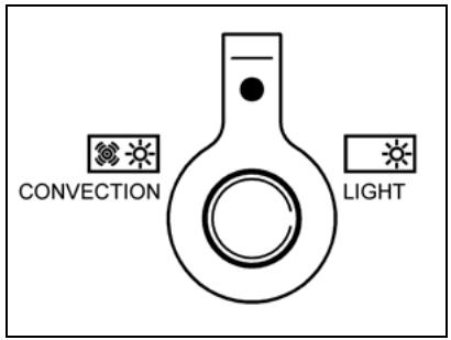
Turn the knob anti clockwise for activation of the convection fan +light
Turn the knob clockwise to turn on the oven light.
| CONVECTION GAS OVEN COOKING TABLE | |||
| TEMP °F/ °C | HEIGHT | MINUTES | |
| MEAT | |||
| PORK ROAST | 320-340/160-170 | 3 | 70-100 |
| BEEF ROAST (YOUNG STEER) | 340-355/170-180 | 3 | 65-90 |
| BEEF ROAST | 340-375/170-190 | 3 | 40-60 |
| VEAL ROAST | 320-355/160-180 | 3 | 65-90 |
| LAMB ROAST | 285-320/140-160 | 3 | 100-130 |
| ROAST BEEF | 355-375/180-190 | 3 | 40-45 |
| ROAST HARE | 340-355/170-180 | 3 | 30-40 |
| ROAST RABBIT | 320-340/160-170 | 3 | 80-100 |
| ROAST TURKEY | 320-340/160-170 | 3 | 160-240 |
| ROAST GOOSE | 320-355/160-180 | 3 | 120-160 |
| ROAST DUCK | 340-355/170-180 | 3 | 100-160 |
| ROAST CHICKEN | 355/180 | 3 | 70-90 |
| FISH | 320-355/160-180 | 3 / 4 | |
| PASTRY | |||
| FRUIT PIE | 355-390/180-200 | 3 | 40-50 |
| TEA CAKE | 390-430/200-220 | 3 | 40-45 |
| BRIOCHES | 340-355/170-180 | 3 | 40-60 |
| SPONGE CAKE | 390-445/200-230 | 3 | 25-35 |
| RING CAKE | 320-355/160-180 | 3 | 35-45 |
| SWEET PUFF PASTRIES | 355-390/180-200 | 3 | 20-30 |
| RAISIN LOAF | 445-480/230-250 | 3 | 30-40 |
| STRUDEL | 320/160 | 3 | 25-35 |
| SAVOIA COOKIES | 300-355/150-180 | 3 | 50-60 |
| APPLE FRITTERS | 355-390/180-200 | 3 | 18-25 |
| SAZOIARDI SANDWICH | 340-355/170-180 | 3 | 30-40 |
| TOAST SANDWICH | 445-480/230-250 | 4 | 7 |
| BREAD | 390-430/200-220 | 4 | 40 |
| PIZZA | 390-430/200-220 | 3 | 20 |
The gas broiler is controlled with the same gas oven knob, but turning it clockwise instead of counterclockwise (see the gas oven use instructions), matching the symbol with the indicator. The broiler burner always operates at maximum and therefore there is no minimum position. In addition, it is equipped with a safety device to prevent the flame from going out. The gas broiler can also be ignited in different ways:

- Manual lighting: Just completely open the oven door, turn the knob so that the relative symbol matches the indicator, while pressing the knob, and, at the same time, put a lit match next to the burner. Make sure that the burner is completely lit and after about 10 seconds release the knob. Make sure that the burner remains on, otherwise repeat the operation.
- Electric ignition: In this case, completely open the oven door, turn the knob so that the relative symbol matches the indicator and, while keeping the knob pressed, press the knob with the spark symbol. Wait about 10 seconds after the burner has been completely lit and then release the knob. Make sure that the burner remains on, otherwise repeat the operation.
ATTENTION: To use broiler please utilize the proper broiler grid installed inside the grid enamelled tray supplied with the appliance; broiler tray shall be supported by oven grid.
WARNING: As with the oven, the broiler must be lit with the door completely open.
The gas broiler can be used to broil foods on the oven shelf.
The gas broiler operation is indicated by a blue light
IMPORTANT: when broiling food keep the door closed..
Verify that aspect flame of the broiler burner be completely blue and with an aspect as indicated in figure
Note: The use of a gas cooking appliance produces heat and humidity in the room where it is installed. Therefore, proper ventilation in the room is needed and natural ventilation openings must remain unobstructed and activating the mechanical exhaust fan/range hood. Intensive and continuous use of the appliance may require additional ventilation, for example by opening a window, or increasing the power of the mechanical exhaust fan/range hood, if installed.
Note: the cooker is equipped with the cooling fan that starts operation each time the oven knob is on a position different from 0 (zero). The fan circulates the air between the control panel and the oven door and also allows the control panel and the oven door stay at a warm temperature during the appliance operation in any condition.
CLEANING THE APPLIANCE:
Never use abrasive cleaners
Before cleaning the appliance it should be disconnected from the power supply.
Cleaning the work surface: periodically clean the burner heads, the cast iron pan supports and the burner caps using warm water.
Any spillage must always be removed as soon as possible using a rag.
If it become difficult to open or close a valve, do not force it, but immediately request the assistance of the technical service personnel.
Cleaning the enamelled parts: Enamelled parts should be cleaned frequently with soapy water. Never use abrasive powder. Do not leave acidi or alkaline substances on the enamelled parts (such as vinegar, lemon juice, salt, tomato sauce, etc.) and do not wash the enamelled parts while they are still hot.
Cleaning the stainless steel parts: Clean the parts with soapy water and dry them with a soft cloth. The shine is maintained by periodically using specific stainless steel cream cleaner. Never use abrasive powders.Use specific stainless steel cream cleaner to eliminate the glue remains after the elimination of the blue plastic protection film on the worktop after installation.
Cleaning the burner caps: Lift the burner caps from the burner heads and wash them in soapy water and dry thoroughly. Before replacement on the burner head ensure that the holes are not clogged.
Cleaning the inner glass door: Clean the glass with warm soapy water using a sponge. A spatula can be used to remove burner fat if used gently.
ATTENTION: while cleaning the door make sure to avoid any spillage in the venting holes on the top part of the door. To clean inside the door it is necessary to disassemble the door through a service engineer.
ATTENTION: for further details about cleaning of the appliance, please contact your appliance retailer.
AFTER SALE SERVICE:
Please note here below details for after save service.
Refer to warranty certificate for warranty conditions
Dealer/Importer:
Name, address, phone
| SERVICE CENTERS | |
| Name | Phone |
MANUFACTURER:
BERTAZZONI SPA
VIA PALAZZINA, 8 - 42016 - GUASTALLA (REGGIO E.) ITALY
Tel. 0522/226411 - telecom 0522/226440 - http://www.bertazzoni-italia.com
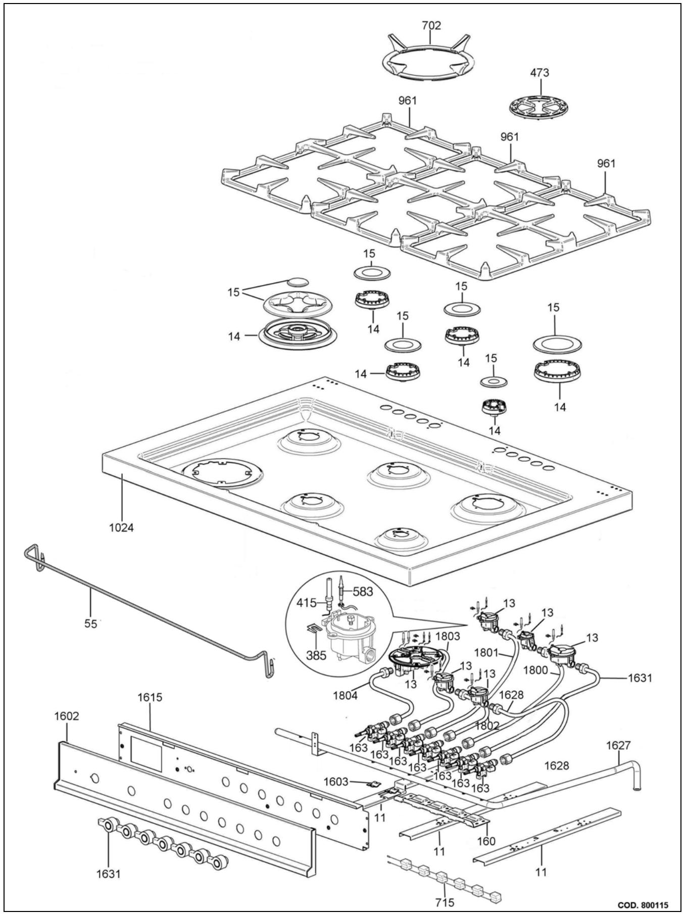
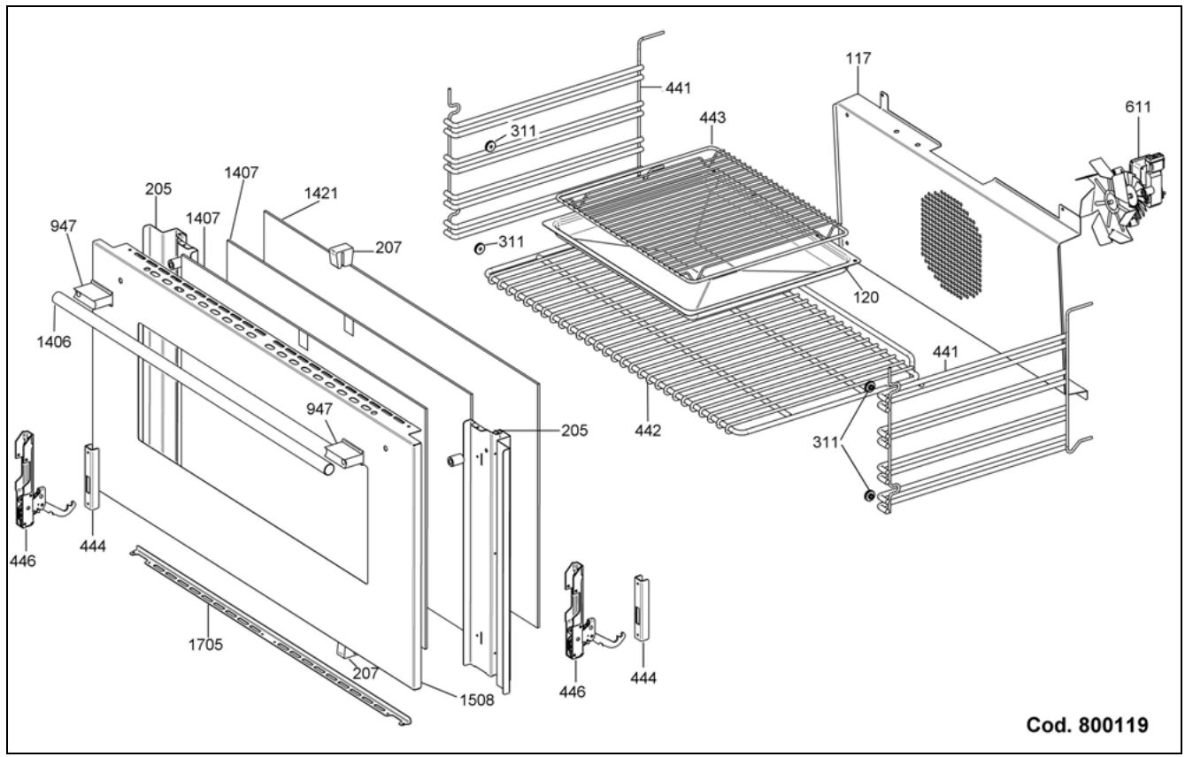
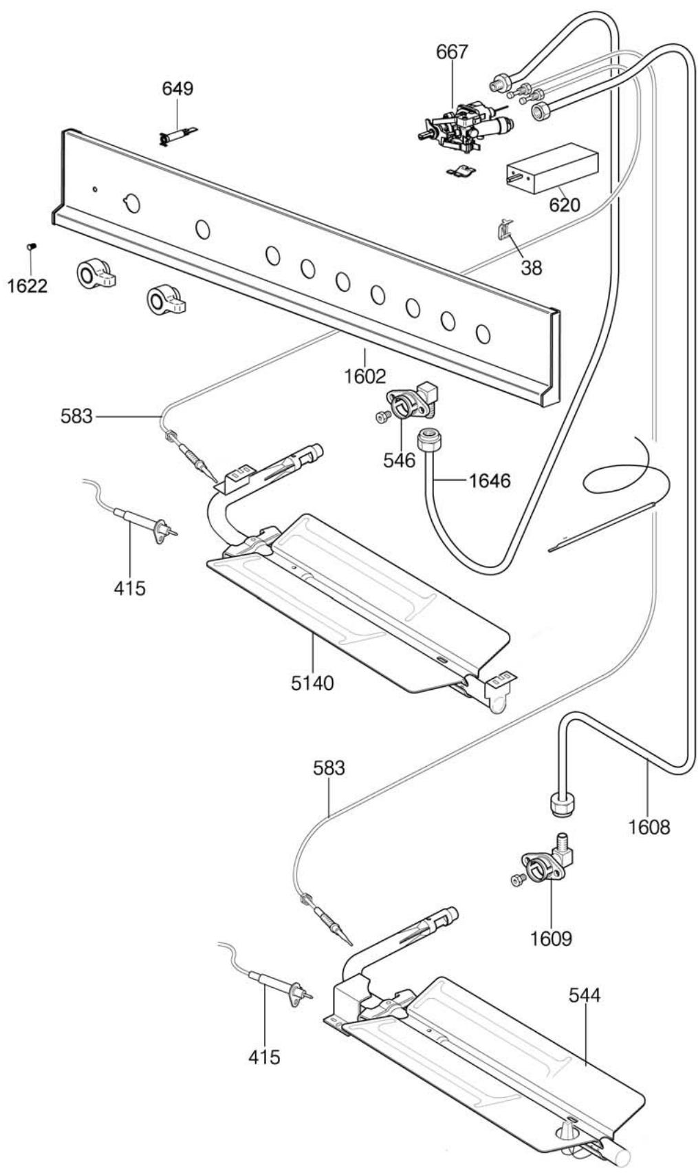
SPARE PART LIST
| Quantity | ||||
| Number Drawing | Code | Description | M3W0GTU4X5AUA | M3Y0GTU4X5AUA |
| 1 | 601736 | CIRCUIT DIAGRAM | 1 | 1 |
| 11 | 202317 | PART FOR BURNER FIXING | 3 | 3 |
| 11 | 202386 | PART FOR DUAL WOK AND SEMI RAPID BURNERS | 1 | 1 |
| 13 | 510507 | SMALL BURNER | 1 | 1 |
| 13 | 510508 | SEMI RAPID BURNER | 1 | 3 |
| 13 | 510509 | RAPID BURNER | 1 | 1 |
| 13 | 510511 | DUAL BURNER | 1 | 1 |
| 14 | 504128 | SMALL FLAME SPREADER | 1 | 1 |
| 14 | 504129 | MEDIUM FLAME SPREADER | 2 | 3 |
| 14 | 504130 | RAPID FLAME SPREADER | 1 | 1 |
| 14 | 504189 | ULTRA RAPID FLAME SPREADER | 1 | 1 |
| 15 | 504160 | COVER FOR SMALL FLAME SPREADER | 1 | 1 |
| 15 | 504161 | COVER FOR MEDIUM BURNER | 2 | 3 |
| 15 | 504162 | COVER FOR RAPID BURNER | 1 | 1 |
| 15 | 504186 | COVER OUT FOR DUAL BURNER FLAME SPREADER | 1 | 1 |
| 15 | 504187 | COVER IN FOR DUAL BURNER FLAME SPREADER | 1 | 1 |
| 38 | 306003 | THERMOSTAT CLIP | 2 | 2 |
| 55 | 404198 | WORKTOP FRONTGUARD | 1 | 1 |
| 105 | 202382 | UP SUPPORT FOR AXIAL COOLIN FAN | 1 | 1 |
| 106 | 202383 | DOWN SUPPORT FOR AXIAL COOLIN FAN | 1 | 1 |
| 109 | 202384 | INSIDE FLAP DOOR | 1 | 1 |
| 117 | 101353 | PROTECTION FOR VENTILATED OVEN | 1 | 1 |
| 120 | 101048 | BLACK OVEN DRIP TRAY | 1 | 1 |
| 138 | 202369 | DISHWARMER BOTTOM | 1 | 1 |
| 160 | 202262 | BRIDLE FOR FIXING GAS VALVES | 1 | 1 |
| 163 | 502150 | GAS VALVE BY PASS 065 | 1 | 1 |
| 163 | 502152 | GAS VALVE BY PASS 036 | 2 | 3 |
| 163 | 502179 | GAS VALVE BY PASS 029 | 2 | 2 |
| 163 | 502180 | GAS VALVE BY PASS 047 | 1 | 1 |
| 205 | 410561 | RIGHT LONGHERON FOR GLASS DOOR | 1 | 1 |
| 205 | 410562 | LEFT LONGHERON FOR GLASS DOOR | 1 | 1 |
| 207 | 308034 | BUMPER | 2 | 2 |
| 274 | 202391 | CROSS MEMBER | 1 | 1 |
| 311 | 309010 | RING FOR GRID SUPPORT | 4 | 4 |
| 329 | 309141 | INSIDE DOOR SPACER | 2 | 2 |
| 385 | 306024 | STOP SPRING FOR SPARK PLUG | 6 | 7 |
| 415 | 415054 | SPARK PLUG 350MM | 1 | 2 |
| 415 | 415057 | SPARK PLUG 700MM | 3 | 3 |
| 415 | 415060 | SPARK PLUG FOR OVEN AND BROILER | 1 | 1 |
| 415 | 415071 | SPARK PLUG FOR DUAL BURNER | 2 | 2 |
| 430 | 415065 | ACCUMULATOR | 2 | 2 |
| 436 | 402126 | BACK FIBER GLASS | 1 | 1 |
| 441 | 404187 | RIGHT GRID FOR OVEN | 1 | 1 |
| 441 | 404188 | LEFT GRID FOR OVEN | 1 | 1 |
| 442 | 404189 | GRID FOR OVEN | 1 | 1 |
| 443 | 404497 | GRID FOR TRAY F6-M6 | 1 | 1 |
| 444 | 202393 | FLASK HINGE | 2 | 2 |
| 446 | 405073 | OVEN DOOR HINGE | 2 | 2 |
| 473 | 404117 | REDUCTION GRID | 1 | 1 |
| 478 | 410558 | FLAP DOOR | 1 | 1 |
| 544 | 504163 | OVEN BURNER +BAFFLE+ SPARK PLUG +THERMOC | 1 | 1 |
| 546 | 505013 | SUPPORT FOR BROILER BURNER NOZZLE | 1 | 1 |
| 583 | 508021 | TERMOCOUPLE MM600 | 2 | 2 |
| 583 | 508025 | TERMOCOUPLE MM300 | 1 | 2 |
| 583 | 508026 | THERMOCOUPLE OVEN BURNER | 1 | 1 |
| 583 | 508027 | TERMOCOUPLE MM800 | 1 | 1 |
| 583 | 508032 | TERMOCOUPLE FOR DUAL BURNER | 2 | 2 |
| 611 | 603020 | MOTOVENTILATOR | 1 | 1 |
| 612 | 603019 | COOLING FAN | 1 | 1 |
| 620 | 602039 | COMMUTATOR | 1 | 1 |
| 623 | 608046 | OVEN BULB WITH HOLDER | 2 | 2 |
| 648 | 601991 | TERMINAL SEPARATOR | 1 | 1 |
| 649 | 608044 | SMALL WARNING LIGHT | 2 | 2 |
| 667 | 503084 | THERMOSTAT | 1 | 1 |
| 702 | 408058 | ADAPTER FOR WOK BURNER PAN SUPPORT | 1 | 1 |
| 715 | 604063 | DASYCHAIN SWITCH | 1 | |
| 715 | 604062 | DASYCHAIN SWITCH | 1 | |
| 760 | 202404 | BACK ENCLOSURE METAL PANEL | 1 | 1 |
| 770 | 202405 | WARMER DROWER UPPERSIDE PROTECTION PANEL | 1 | 1 |
| 917 | 200327 | SIDE INOXIDABLE | 2 | 2 |
| 929 | 202389 | RIGHT VERTICAL VENT | 1 | 1 |
| 930 | 202214 | FEET SUPPORT | 2 | 2 |
| 940 | 201168 | FIXING FOR WORK TABLE | 2 | 2 |
| 947 | 403343 | HANDLE TERMINAL | 2 | 2 |
| 961 | 408052 | CAST IRON PAN SUPPORT 2 BURNERS | 2 | 3 |
| 961 | 408053 | CAST IRON PAN SUPPORT 1 BURNER | 1 | |
| 1031 | 401904 | GAS VALVE KNOB | 6 | 7 |
| 1031 | 401905 | GAS THERMOSTAT KNOB | 1 | 1 |
| 1031 | 401906 | ELECTRIC KNOB | 1 | 1 |
| 1143 | 410565 | FRONT RISER | 1 | 1 |
| 1143 | 410566 | REAR RISER | 1 | 1 |
| 1406 | 403344 | OVEN DOOR HANDLE | 1 | 1 |
| 1407 | 406370 | OVEN DOOR GLASS | 2 | 2 |
| 1411 | 411090 | GASKET FOR OVEN FRONT 4 SIDE | 1 | 1 |
| 1411 | 411091 | GASKET FOR OVEN FRONT 1 SIDE | 1 | 1 |
| 1415 | 602040 | COOLING FAN FAILURE THERMAL CUT-OUT | 1 | 1 |
| 1421 | 406369 | INTERNAL OVEN GLASS | 1 | 1 |
| 1508 | 410560 | STAINLESS STEEL OVEN DOOR | 1 | 1 |
| 1602 | 210458 | CONTROL PANEL | 1 | |
| 1602 | 210459 | CONTROL PANEL | 1 | |
| 1603 | 309119 | BRIDLE FOR FIXING GAS VALVES/THERMOSTAT | 1 | 2 |
| 1603 | 309119 | BRIDLE FOR FIXING GAS VALVES/THERMOSTAT | 1 | 1 |
| 1608 | 501632 | ALL.TUBE FOR OVEN BURNER | 1 | 1 |
| 1609 | 505032 | OVEN NOZZLE SUPPORT | 1 | 1 |
| 1611 | 201166 | REAR VENT STACK | 2 | 2 |
| 1611 | 201167 | FRONT VENT STACK | 2 | 2 |
| 1614 | 201165 | BACK PANEL | 1 | 1 |
| 1615 | 202388 | CONTROL SUPPORT | 1 | 1 |
| 1622 | 608025 | SMALL RED BUD | 1 | 1 |
| 1622 | 608045 | SMALL BLUE BUD | 1 | 1 |
| 1624 | 200317 | WORK TABLE | 1 | |
| 1624 | 200316 | WORK TABLE | 1 | |
| 1627 | 501629 | GAS COLLECTOR | 1 | |
| 1627 | 501628 | GAS COLLECTOR | 1 | |
| 1628 | 501634 | TUBE FOR RIGHT FRONT BURNER | 1 | 1 |
| 1631 | 501635 | TUBE FOR RIGHT BACK BURNER | 1 | 1 |
| 1639 | 202390 | LEFT VERTICAL VENT | 1 | 1 |
| 1644 | 414047 | FEET GALAXY | 4 | 4 |
| 1645 | 414031 | BASE BOARD PART | 4 | 4 |
| 1646 | 501633 | BROILER THERMOSTAT TUBE | 1 | 1 |
| 1661 | 202111 | PROTECTION PANEL FOR OVEN BURNER M9/D2 | 1 | 1 |
| 1705 | 410563 | OVEN GLASS SUPPORT | 1 | 1 |
| 1807 | 501637 | TUBE FOR FRONT LEFT BURNER | 1 | |
| 1801 | 501636 | TUBE FOR LEFT BACK BURNER | 1 | 1 |
| 1800 | 501640 | REAR CENTRAL TUBE | 1 | |
| 1802 | 501641 | FRONT CENTRAL TUBE | 1 | |
| 1805 | 501638 | CENTRAL TUBE | 1 | |
| 1806 | 501639 | EXTERNAL CENTRAL TUBE | 1 | |
| 1804 | 501642 | TUBE FOR INTERNLA DUAL BURNER | 1 | |
| 1803 | 501643 | TUBE FOR EXTERNAL DUAL BURNER | 1 | |
| 4106 | 405047 | HINGE FOR FLAP DOOR | 2 | 2 |
| 4301 | 200328 | RIGHT SIDE PROFILE | 1 | 1 |
| 4302 | 200329 | LEFT SIDE PROFILE | 1 | 1 |
| 5140 | 504185 | BROILER BURNER | 1 | 1 |
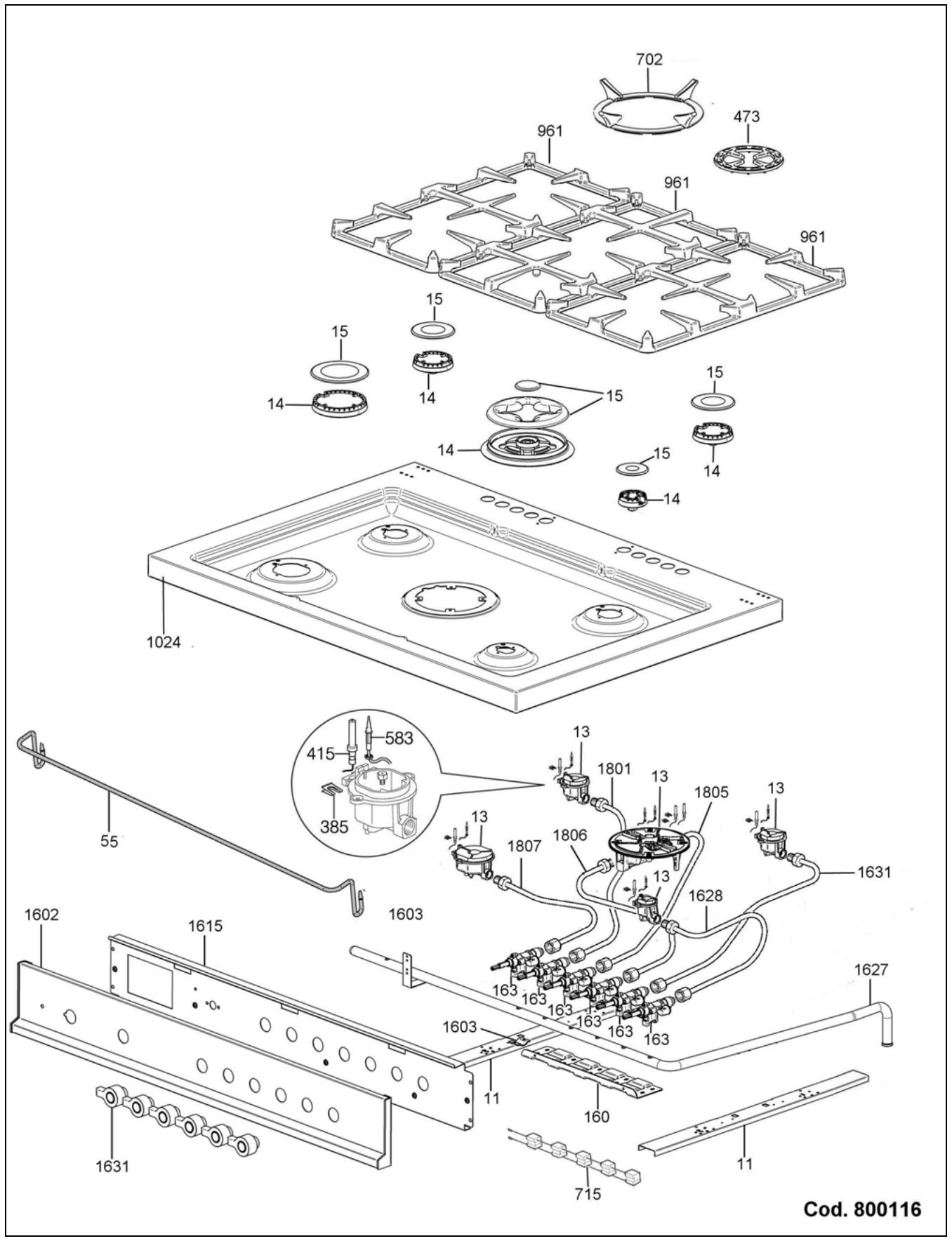
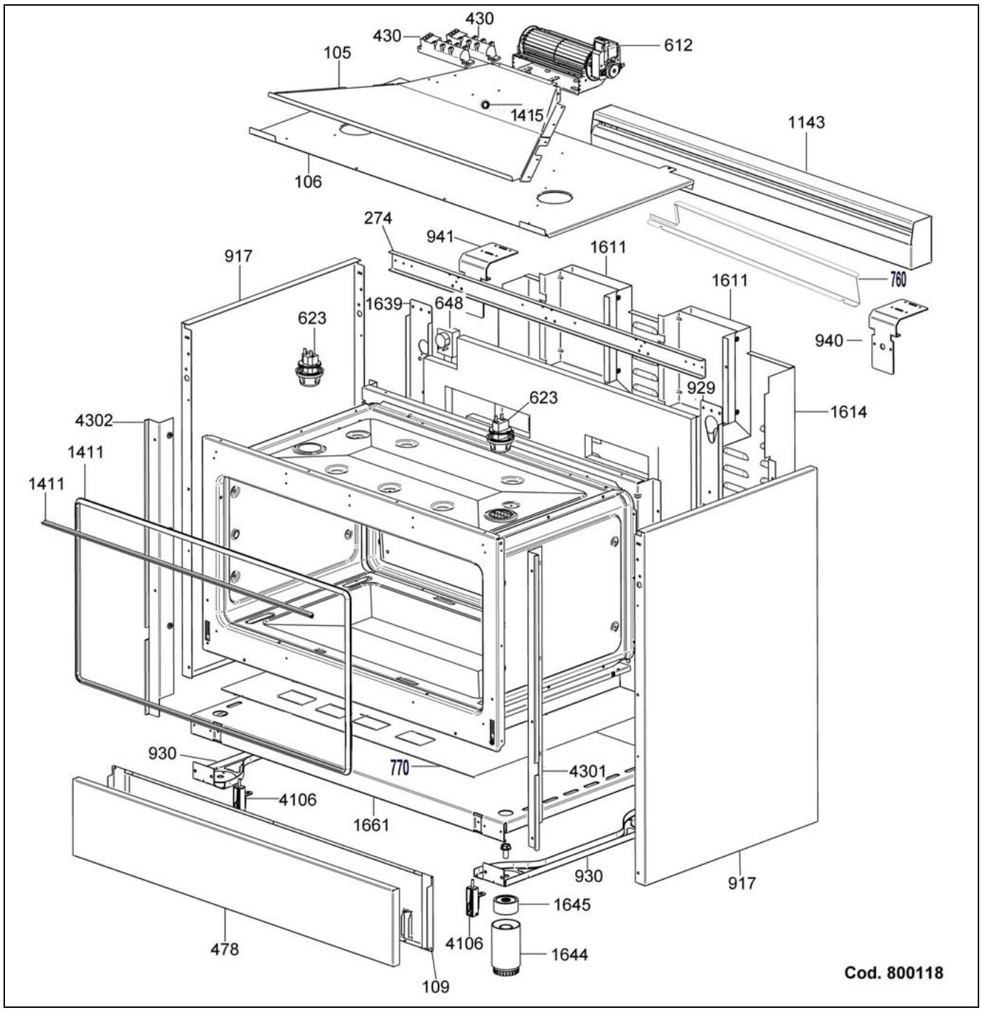
Cod. 800117
- Models X365GGVX (X36 5 00 X) [M3W0GTU4X(2 or 5)A] Models X366GGVX (X36 6 00 X) [M3Y0GTU4X(2 or 5)A] IMPORTANT - PLEASE READ AND FOLLOW
- Warning!
- IMPORTANT: SAVE FOR LOCAL ELECTRICAL INSPECTOR'S USE. READ AND SAVE THESE INSTRUCTIONS FOR FUTURE REFERENCE. OBSERVE ALL GOVERNING CODES AND ORDINANCES.
- WHAT TO DO IF YOU SMELL GAS
- WARNING
- Installation instructions
- Requirements
- INSTALLATION MANUAL
- ANTI-TIP STABILITY DEVICE INSTALLATION INSTRUCTIONS
- Height adjustable legs:
- BACKGUARD INSTALLATION INSTRUCTION
- WORKTOP FRONTGUARD INSTALLATION INSTRUCTIONS
- INSTALLATION SIDE-BY-SIDE TO KITCHEN CABINET
- COOKER HOOD INSTALLATION
- ELECTRICAL CONNECTION
- GAS CONNECTION
- Manual Shut-off Valve:
- Pressure Regulator(see fig. in this chapter)
- Flexible Connections:
- PERFORMANCE CHECKLIST
- FINAL PREPARATION
- REPLACEMENT PARTS
- Conversion to different types of gas
- Adaptation of the pressure regulator for use with different type of gas
- - CHANGING THE NOZZLES FOR USE WITH OTHER TYPES OF GAS:
- Follow the instructions below to change the oven burner nozzle:
- Follow the instructions below to change the broiler burner nozzle:
- Models X366GGVX (X36 6 00 X) [M3Y0GTU4X(2 or 5)A]
- Adapting to different types of gas
- Models X365GGVX (X36 5 00 X) [M3W0GTU4X(2 or 5)A]
- REGULATION OF BURNERS
- Primary air adjustment:
- SERVICE & MAINTENANCE INSTRUCTIONS
- USER MANUAL
- WARNING:
- DESCRIPTIONS
- DESCRIPTEV CAPTION FOR HOB
- DESCRIPTION OF HOBS
- CONTROL PANEL DESCRIPTION
- USING BURNERS
- Manual ignition:
- Automatic electric ignition:
- Tips for using burners correctly:
- Correct usage of pans:
- USING THE GAS OVEN
- - Electric ignition
- CLEANING THE APPLIANCE:
- Never use abrasive cleaners
- AFTER SALE SERVICE:
- MANUFACTURER:
- BERTAZZONI SPA
Brand : BERTAZZONI
Model : X365GGVX
Category : Gas stove