MULTICHOICE 13-14 - Thermostatic shower valve DELTA - Free user manual and instructions
Find the device manual for free MULTICHOICE 13-14 DELTA in PDF.
User questions about MULTICHOICE 13-14 DELTA
0 question about this device. Answer the ones you know or ask your own.
Ask a new question about this device
Download the instructions for your Thermostatic shower valve in PDF format for free! Find your manual MULTICHOICE 13-14 - DELTA and take your electronic device back in hand. On this page are published all the documents necessary for the use of your device. MULTICHOICE 13-14 by DELTA.
USER MANUAL MULTICHOICE 13-14 DELTA
To reduce the risk of injury due to hot water burns, make sure the enclosed labels are applied where specified on the label.
DOCUMENTOS IMPORTANTES INCLUIDOS
AVISO:
NOTICE TO INSTALLER: Place this label on the water heater next to the temperature adjustment knob.
WARNING:
These series of tub/shower valves do not adjust automatically for changes in temperature at the hot water heater or inlet. If the temperature setting of the hot water heater or inlet is changed, the setting on these valves must be adjusted manually! Failure to re-adjust the valve may result in hot water burns or extreme cold resulting from variations in line pressure (such as when a dishwasher or washing machine is in use while you are taking a shower). After installation, verify that the rotational limit stop (13/14/17 series) or temperature knob (17T series) on the valve is set so that changes in line pressure or temperature do not result in uncomfortable water temperature changes. If the temperature setting of the hot water heater or inlet is changed after installation of the valve, the setting of the rotational limit stop or temperature knob also must be changed! Consult the installation instruction sheet for instructions on how to make this setting, or call us at 1-800-345-DELTA.
Rotational Limit Stop is located behind the disc.
text_image
13 / 14 Series Hotter Más Caliente Plus Chaud 1st Position Primera Posición 1ère Position17 Series
Hotter
Más
Calient
Plus
Chaud
17T Series
natural_image
Line drawing of a cylindrical mechanical component with a droplet inserted, showing motion arrows (no text or symbols)NOTICE TO INSTALLER: Place this label close to the valve where the owner will see it, such as inside the door of a cabinet or vanity.
WARNING:
Water temperature changes due to seasonal or other inlet variations, such as changing the setting on the hot water heater may require adjustment of the rotational limit stop (13/14/17 Series) or temperature knob (17T Series) on your tub/shower valve to ensure a safe maximum temperature. These valve series do not automatically adjust for inlet temperature changes. If changes occur and you are not sure how to make the necessary rotational limit stop or temperature knob adjustments, please consult the installation instruction sheet provided with this valve or call 1-800-345-DELTA. These valve series are designed to minimize the effects of outlet water temperature changes due to inlet pressure changes, commonly caused by dishwashers, washing machines, toilets and the like. They may not provide protection from hot water burns when there is a failure of other temperature controlling devices elsewhere in the plumbing system. After making the necessary adjustments please fill in the information below. This valve/system has been set by the person listed below to ensure a safe maximum temperature. Any change in the setting may raise the discharge temperature above the limit considered safe and could lead to hot water burns. If this label has not been completed, you should verify that the rotational limit stop or temperature knob has been properly adjusted to suit your individual installation. The installation instruction sheet supplied with the valve provides information on how to make this setting.
Rotational Limit Stop is located behind the disc.
13 / 14 Series
text_image
Hotter Más Caliente Plus Chaud 1st Position Primera Posición 1ère Position17 Series
Hotter
Más
Caliente
Plus
Chaud
Colder
Más
Fría
Plus
Froid
Write purchased model number here.
You May Need


Table of Contents:
| Warranties | Page 2 |
| 13/14 Series Installation Instructions | Pages 3 - 6 |
| 17 Series Installation Instructions | Pages 7 - 10 |
| 17T Series Installation Instructions | Pages 11-14 |
| Maintenance | Pages 14-15 |
| Cartridge Summary Reference Sheet | Page 16 |
| Replacement Parts | Pages 17 - 46 |
THIS VALVE MEETS OR EXCEEDS THE FOLLOWING STANDARDS:
ASME A112.18.1/CSA B125.1 and ASSE 1016.
CAUTION: This system/device must be set by the installer to ensure safe, maximum temperature. Any change in the setting may raise the discharge temperature above the limit considered safe and may lead to hot water burns.
NOTICE TO INSTALLER: CAUTION!—As the installer of this valve, it is your responsibility to properly INSTALL and ADJUST this valve per the instructions given. This valve does not automatically adjust for inlet temperature changes, therefore, someone must make the necessary Rotational Limit Stop or temperature knob adjustments at the time of installation and further adjustments may be necessary due to seasonal water temperature change. YOU MUST inform the owner/user of this requirement by following the instructions. If you or the owner/user are unsure how to properly make these adjustments, please refer to page 5 (13 / 14 series), page 10 (17 series) or page 14 (17T series) and if still uncertain, call us at 1-800-345-DELTA.
After installation and adjustment, you must affix
your name, company name and the date you adjusted the Rotational Limit Stop or temperature knob to the caution label provided and apply or attach the label to the back side of the closest cabinet door and the warning label to the water heater. Leave this Instruction Sheet for the owner's/user's reference.
WARNING: This pressure balanced or thermostatic bath valve is designed to minimize the effects of outlet water temperature changes due to inlet pressure changes, commonly caused by dishwashers, washing machines, toilets and the like. It may not provide protection from hot water burns when there is a failure of other temperature controlling devices elsewhere in the plumbing system, if the rotational limit stop or temperature knob is not properly set or if the hot water temperature is changed after the settings are made or if the water inlet changes due to seasonal changes.
WARNING: Do not install a shut-off device on either outlet of this valve. When this type of device shuts off the water flow, it can defeat the ability of the valve to balance the hot and cold water pressures.
Lifetime Faucet and Finish Limited Warranty
All parts and finishes of the Delta® faucet are warranted to the original consumer purchaser to be free from defects in material & workmanship for as long as the original consumer purchaser owns their home. Delta Faucet Company recommends using a professional plumber for all installation & repair.
Delta will replace, FREE OF CHARGE, during the warranty period, any part or finish that proves defective in material and/or workmanship under normal installation, use & service. Replacement parts may be obtained by calling 1-800-345-DELTA (in the U.S. and Canada) or by writing to:
In the United States: Delta Faucet Company Product Service 55 E. 111th Street Indianapolis, IN 46280
In Canada: Masco Canada Technical Service Centre 420 Burbrook Place London, ON N6A 4L6
This warranty is extensive in that it covers replacement of all defective parts and even finish, but these are the only two things that are covered. LABOR CHARGES AND/OR DAMAGE INCURRED IN INSTALLATION,
REPAIR, OR REPLACEMENT AS WELL AS ANY OTHER KIND OF LOSS OR DAMAGES ARE EXCLUDED. Proof of purchase (original sales receipt) from the original consumer purchaser must be made available to Delta for all warranty claims. THIS IS THE EXCLUSIVE WARRANTY BY DELTA FAUCET COMPANY, WHICH DOES NOT MAKE ANY OTHER WARRANTY OF ANY KIND, INCLUDING THE IMPLIED WARRANTY OF MERCHANTABILITY.
This warranty excludes all industrial, commercial & business usage, whose purchasers are hereby extended a five year limited warranty from the date of purchase, with all other terms of this warranty applying except the duration of the warranty. This warranty is applicable to Delta® faucets manufactured after January 1, 1995.
Some states/provinces do not allow the exclusion or limitation of incidental or consequential damages, so the above limitation or exclusion may not apply to you. Any damage to this faucet as a result of misuse, abuse, or neglect, or any use of other than genuine Delta® replacement parts WILL VOID THE WARRANTY.
This warranty gives you specific legal rights, and you may also have other rights which vary from state/province to state/province. It applies only for Delta® faucets installed in the United States of America, Canada, and Mexico.
© 2009 Masco Corporation of Indiana
Delta HDF Limited Warranty
All parts of the Delta HDF faucet are warranted to the original consumer purchaser to be free from defects in material and workmanship for a period of five (5) years. This warranty is made to the original consumer purchaser and shall be effective from date of purchase as shown on purchaser's receipt.
Delta will replace, FREE OF CHARGE, during the warranty period, any part which proves defective in material and/or workmanship under normal installation, use and service. Replacement parts can be obtained from your local dealer or distributor listed in the telephone directory or by returning the part along with the purchaser's receipt to our factory, TRANSPORTATION CHARGES PREPAID, at the address listed. THIS WARRANTY IS THE ONLY EXPRESS WARRANTY MADE BY DELTA. ANY CLAIMS MADE UNDER THIS WARRANTY MUST BE MADE DURING THE FIVE YEAR PERIOD REFERRED TO ABOVE. ANY IMPLIED WARRANTIES, INCLUDING THE IMPLIED WARRANTY OF MERCHANTABILITY OR
FITNESS FOR A PARTICULAR PURPOSE, ARE LIMITED IN DURATION TO THE DURATION OF THIS WARRANTY. LABOR CHARGES AND/OR DAMAGE INCURRED IN INSTALLATION, REPAIR OR REPLACEMENT AS WELL AS INCIDENTAL AND CONSEQUENTIAL DAMAGES CONNECTED THEREWITH ARE EXCLUDED AND WILL NOT BE PAID BY DELTA.
Some states do not allow limitations on how long an implied warranty lasts, or the exclusion or limitation of incidental or consequential damages, so the above limitations or exclusions may not apply to you.
This warranty gives you specific legal rights, and you may also have other rights which vary from state to state.
This warranty is void for any damage to this faucet due to misuse, abuse, neglect, accident, improper installation, any use violative of instructions furnished by us or any use of replacement parts other than genuine Delta parts.
1
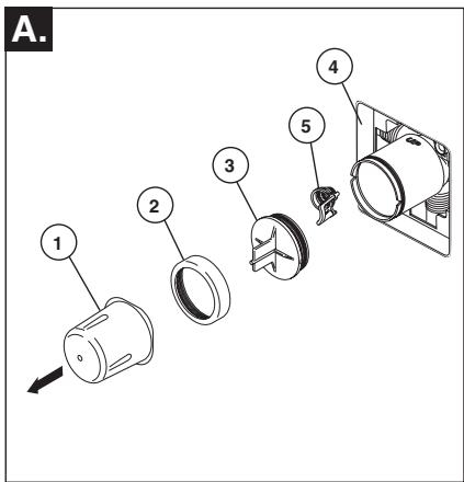
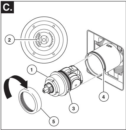
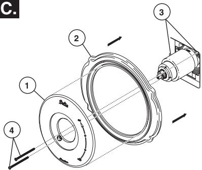
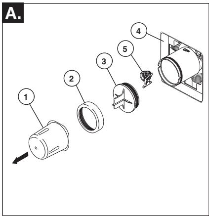
Cartridge Installation
A.
text_image
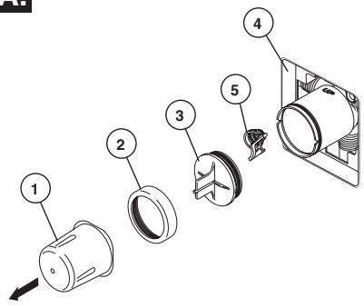
Exploded view diagram of a mechanical assembly with numbered parts for identificationTurn off water supplies. Remove cover (1), bonnet nut (2) and test cap (3) from the body. If this is not a thin wall mounting, the entire plasterguard (4) may be removed. If screen (5) is in place, remove before installing cartridge.
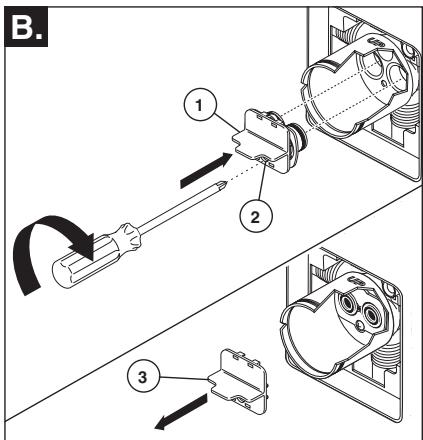
B.
text_image
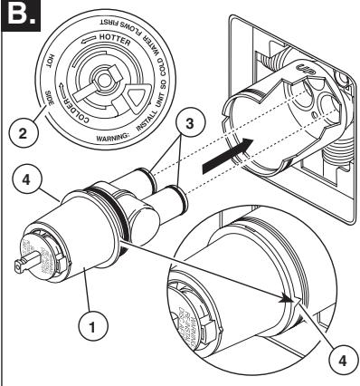
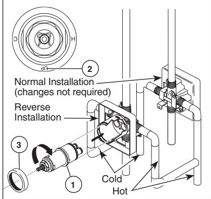
B. 1 2 3 4 5 6 HOTTER WARNING: INSTALL INT SO 1 2 3 4Rotate the cartridge (1) so the words “hot side” (2) appear on the left. Insert cartridge into valve body as shown. Make sure the cartridge tubes and O-rings (3) are properly seated in holes at the base of the body. Ensure the keys on the body are fully engaged with the slots in the body (4).
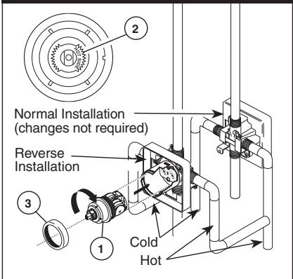
Back to back Installation
Normal Installation (changes not required)
text_image
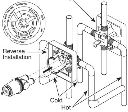
Reverse Installation Cold HotFor back to back or reverse installations (hot on right and cold on left) insert the cartridge with the "hot side" on the right. If you are not making a reverse or back to back installation skip this step and continue with step 1C.
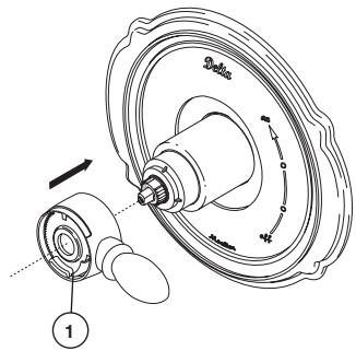
C.
natural_image
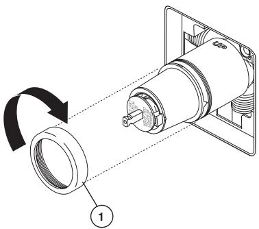
Mechanical assembly diagram showing a rotating component with a numbered label (1), no text or symbols present.Slide bonnet nut (1) over the cartridge and thread onto the body. Hand tighten securely.
13 / 14 Series Installation
2
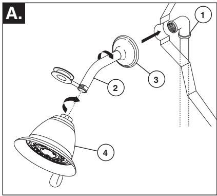
Showerhead and Tub Spout Installation
A.
text_image
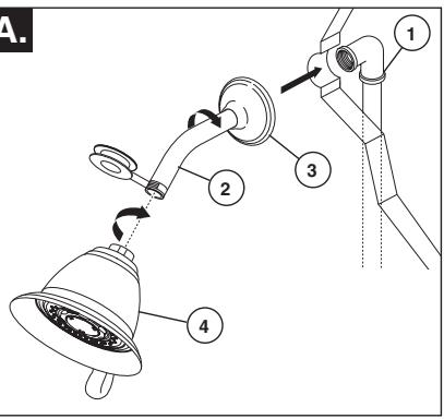
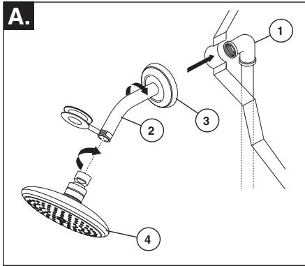
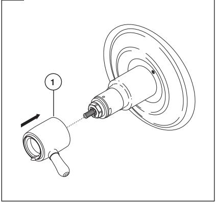
A. 1 2 3 4FOR SHOWERHEAD INSTALLATION:
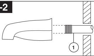
Connect top outlet (1) to shower arm (2) with proper fittings. To prevent damage to finish on shower arm, insert wall end of shower arm into shower flange (3) before screwing arm into riser connection. Thread showerhead (4) onto shower arm. Apply Teflon® tape to pipe threads on both ends. Do not overtighten showerhead.
FOR TUB SPOUT INSTALLATION:
Refer to the installation instructions supplied with your spout. Do not connect deck mount spouts to in-wall valves. Do not use hand showers connected in lieu of a tub spout to a tub/shower valve. Do not use PEX tubing for tub spout drop.
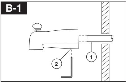
B-1
text_image
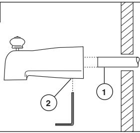
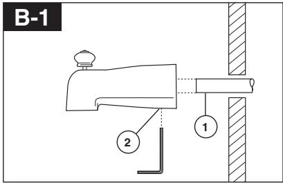
Technical diagram showing a mechanical assembly with labeled parts 1 and 2, likely illustrating a valve or mounting mechanism.Slip-On Installation
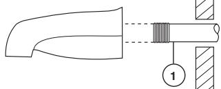
The copper tube (1) must be 1/2" nominal copper. Important: If it is necessary to cut the copper tube, the end must be chamfered free of burrs to prevent cutting or nicking O-ring inside the spout. Slide spout over copper tube flush with the finished tub or wall surface. Tighten set screw (2), but do not overtighten.
B-2
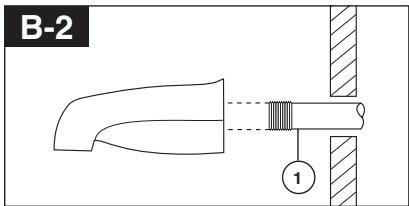
text_image
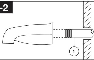
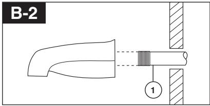
2 ①Iron Pipe Installation
Install threaded pipe nipple (1) to extend past finished wall. Apply Teflon® tape to threads on pipe nipple and screw on tub spout.
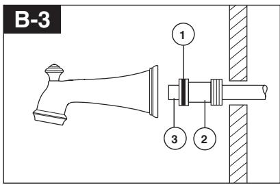
B-3
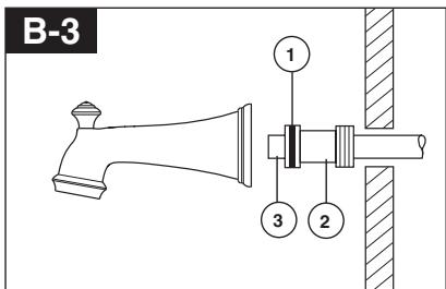
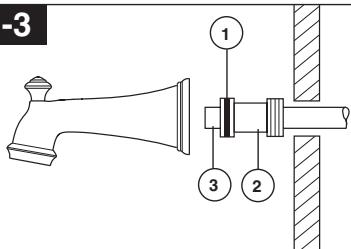
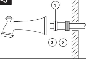
text_image
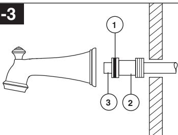
-3 1 3 2Copper Sweat Installation
Remove O-ring (1) from adapter (2). Solder adapter to tube taking care to keep solder away from O-ring groove. CAUTION: NO SOLDER PERMITTED ON OUTSIDE DIAMETER OF ADAPTER ADJACENT TO O-RING GROOVE. Cut off tube (3) and replace O-ring on groove of brass adapter. Thread tub/spout onto adapter, taking care not to damage O-ring, and hand tighten until spout is firmly against finished wall and all slack is taken up behind wall.
3
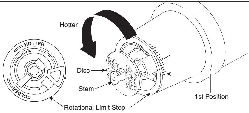
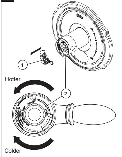
Adjusting the Rotational Limit Stop
text_image
HOTTER HOTTER COLDER Rotational Limit Stop Disc Stem 1st Position HATRIN 1ST METER 1ST METER 1ST METER 1ST METER 1ST METER 1ST METER 1ST METER 1ST METER 1ST METER 1ST METER 1ST METER 1ST METER 1ST METER 1ST METER 1ST METER 1ST METER 1ST METER 1ST METER 1ST METER 1ST METER 1ST MISTER 1ST MISTER 1ST MISTER 1ST MISTER 1ST MISTER 1ST MISTER 1ST MISTERIMPORTANT:
The Rotational Limit Stop is used to limit the amount of hot water available such that, if set properly, the user will not be scalded if the handle accidentally is rotated all the way to “hot” when a person is showering or filling a tub. The first position allows the LEAST amount of hot water to mix with the cold water in the system. In the first position the water will be the coldest possible when the handle is turned all the way to hot. As you move the Rotational Limit Stop counterclockwise, you progressively add more and more hot water in the mix. The last position to the left will result in the greatest amount of hot water to the mix, and the greatest risk of scald injury if someone accidentally turns the valve handle all the way to the hot side while showering or filling a tub.
WARNING: In some instances, setting the Rotational Limit Stop in the hottest position (full counterclockwise) could result in scald injury. It is necessary to adjust the Rotational Limit Stop so that the water coming out of the valve will not scald the user when the handle of the valve is rotated to the hot side.
- According to the majority of industry standards, the maximum allowable temperature of the water exiting the valve is 120^ (Your local plumbing codes may require a water temperature less than 120^ ).
- The Rotational Limit Stop may need to be re-adjusted seasonally if the inlet water temperature changes. For example, during the winter, the cold water temperature is colder than it is during the summer which could result in varying outlet temperatures. A water temperature
for a comfortable bath or shower is typically between 90°F - 110°F.
- Run the water so that the cold water is as cold as it will get and hot water is as hot as it will get. Place the handle on the stem (see page 6, step 4D) and rotate the handle counterclockwise until the handle stops.
- Place a thermometer in a plastic tumbler and hold in the water stream. If the water temperature is above 120^ , the Rotational Limit Stop must be repositioned clockwise to decrease valve outlet water temperature to be less than 120^ or to meet the requirements of your local plumbing codes.
- To adjust the temperature of the water coming out of the valve, pull the disc back to a position where it is possible to remove the Rotational Limit Stop and readjust the teeth engagement position to the desired temperature. Clockwise will decrease the outlet temperature, counterclockwise will increase the outlet temperature. Temperature change per tooth (notch) could be 4^ - 16^ based on inlet water conditions. Repeat as necessary. Push disc until fully seated.
WARNING: Failure to re-install Disc after setting Rotational Limit Stop could result in scald injury.
- MAKE SURE COLD WATER FLOWS FROM THE VALVE FIRST. MAKE SURE WATER FLOWING FROM THE VALVE AT THE HOTTEST FLOW POSSIBLE DOES NOT EXCEED 120°F OR THE MAXIMUM ALLOWED BY YOUR LOCAL PLUMBING CODE.
13 / 14 Series Installation
4
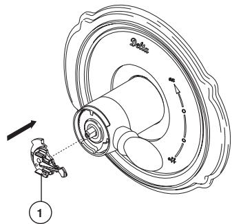
Trim Installation
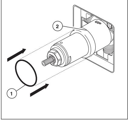
A.
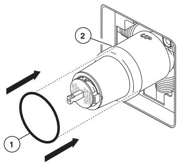
text_image
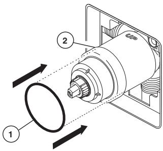
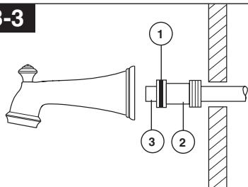
Technical diagram of a mechanical device with labeled components and directional arrows indicating motion or flow.Slide O-ring (1) over cartridge and the bonnet nut (2). The O-ring, which acts as a spacer to steady the sleeve, should rest behind the bonnet nut.
B.
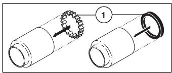
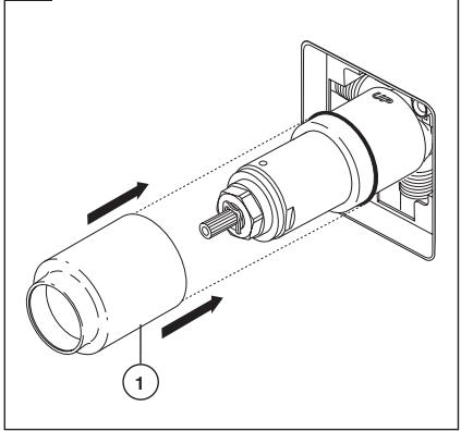
text_image
Diagram showing mechanical assembly with gear and ring components labeled 1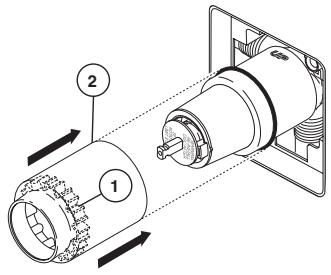
text_image
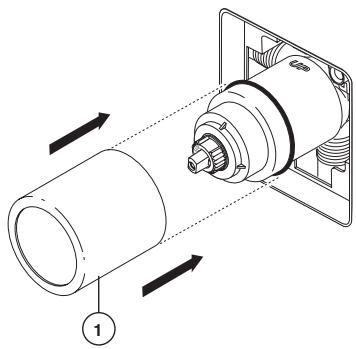
Technical diagram of a mechanical device with labeled components and directional arrows indicating flow or movement.If your model requires a spacer (1), insert it into the sleeve (2) and push it to the front. Slide the sleeve over the cartridge, body and O-ring.
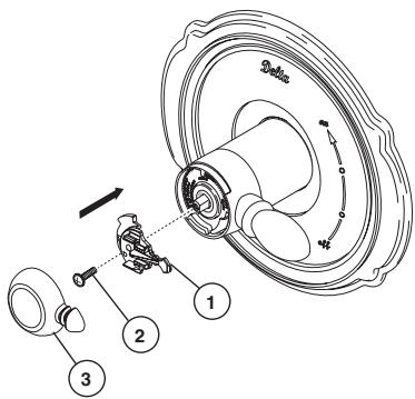
C.
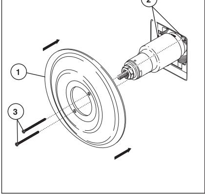
text_image
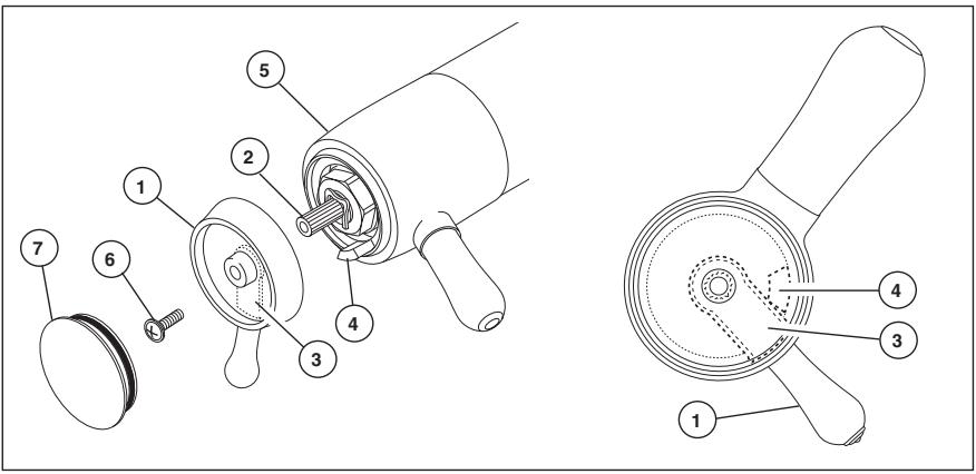
Technical diagram of a mechanical assembly with numbered components and directional arrows indicating motion or flow.Secure the escutcheon (1) and backplate (2) (if your model has one) to the bracket (3) using the 2 screws provided (4). Do not overtighten escutcheon screws.
D.
text_image
Delta MachanUsing an Allen wrench to secure the set screw, install the handle onto the stem.
1
Cartridge Installation
text_image
A. 1 2 3 4 5Turn off water supplies. Remove cover (1), bonnet nut (2) and test cap (3) from the body. If this is not a thin wall mounting, the entire plasterguard (4) may be removed. If screen (5) is in place, remove before installing cartridge.
text_image
B.Insert adapter assembly (1) into valve body. Make sure the adapter assembly is correctly positioned and is pressed all the way down inside body. Secure adapter with the screw (2) provided in the adapter assembly. Remove the retainer (3) from the adapter.
text_image
C. 1 2 3 4 5Rotate cartridge (1) so the words "HOT SIDE" (2) appear on the left. Insert cartridge assembly into valve body. Make sure the key (3) on the cartridge is fully engaged with the slot in the brass body (4). Slide bonnet nut (5) over the cartridge and thread onto the body. Hand tighten securely.
Back to back Installation
text_image
Normal Installation (changes not required) Reverse Installation Cold HotFor back to back or reverse installations (hot on right and cold on left): Rotate cartridge (1) so the words "HOT SIDE" (2) appear on the right. Install the cartridge making sure that the key is fully engaged with the slot in the brass body (See step C). Slide bonnet nut (3) over the cartridge and thread onto the body. Hand tighten securely.
17 Series Installation
2
Showerhead and Tub Spout Installation
text_image
A. 1 2 3 4FOR SHOWERHEAD INSTALLATION:
Connect top outlet (1) to shower arm (2) with proper fittings. To prevent damage to finish on shower arm, insert wall end of shower arm into shower flange (3) before screwing arm into riser connection. Thread showerhead (4) onto shower arm. Apply Teflon® tape to pipe threads on both ends. Do not overtighten showerhead.
FOR TUB SPOUT INSTALLATION:
Refer to the installation instructions supplied with your spout. Do not connect deck mount spouts to in-wall valves. Do not use hand showers connected in lieu of a tub spout to a tub/shower valve. Do not use PEX tubing for tub spout drop.
text_image
B-1 2 1Slip-On Installation
The copper tube (1) must be 1/2" nominal copper. Important: If it is necessary to cut the copper tube, the end must be chamfered free of burrs to prevent cutting or nicking O-ring inside the spout. Slide spout over copper tube flush with the finished tub or wall surface. Tighten set screw (2), but do not overtighten.
text_image
B-2 ①Iron Pipe Installation
Install threaded pipe nipple (1) to extend past finished wall. Apply Teflon® tape to threads on pipe nipple and screw on tub spout.
text_image
B-3 1 2 3Copper Sweat Installation
Remove O-ring (1) from adapter (2). Solder adapter to tube taking care to keep solder away from O-ring groove. CAUTION: NO SOLDER PERMITTED ON OUTSIDE DIAMETER OF ADAPTER ADJACENT TO O-RING GROOVE. Cut off tube (3) and replace O-ring on groove of brass adapter. Thread tub/spout onto adapter, taking care not to damage O-ring, and hand tighten until spout is firmly against finished wall and all slack is taken up behind wall.
3
Trim Installation
A.
text_image
Technical diagram of a mechanical device with labeled parts and directional arrows indicating motion or flow.Slide O-ring (1) over cartridge and the bonnet nut (2). The O-ring, which acts as a spacer to steady the sleeve, should rest behind the bonnet nut.
B.
natural_image
Technical diagram of a mechanical assembly with directional arrows indicating motion (no text or symbols)Slide the sleeve (1) over the cartridge, body and O-ring. Ensure sleeve is properly positioned over the front of cartridge.
C.
text_image
C. 1 2 3 4Secure the escutcheon (1) and backplate (2) (if your model has one) to the bracket (3) with the 2 screws provided (4). Do not overtighten escutcheon screws.
D.
text_image
Dialo 1Install volume control handle (1) with lever to the right, then turn to the on position. DO NOT SECURE WITH SCREW.
17 Series Installation
4
Installation and Adjustment of the Rotational Limit Stop
A.
text_image
Delta ①Place the temperature control knob (1) on volume handle and rotate to the mixed position (if required). DO NOT SECURE WITH SCREW. Turn on water supplies; let the water run until both hot and cold water is as hot/cold as possible. Place thermometer in a plastic tumbler, and hold the tumbler in the water stream. Record the temperature reading.
C.
text_image
Technical diagram of a mechanical assembly with numbered components and directional arrows indicating motion or movement.Secure temperature control knob (1) with screw (2) and snap control cover (3) onto knob. NOTE: Secure screw until handle wobble is reduced, DO NOT FULLY
TIGHTEN. Overtightening will result in difficulty to operate temperature control knob. Screw is self locking.
B.
text_image
3ds 1 2 Hotter ColderIf the water temperature is above 120^ F, remove the temperature control knob (1) and rotate the limit stop (2) clockwise one tooth for every 4^ F - 6^ F (approximate) change in temperature. If water temperature is cooler than desired, rotate the limit stop counterclockwise.
IMPORTANT: The first position of the Rotational Limit Stop (the Limiter) is that position that restricts the rotation of the stem the most and is at the maximum clockwise setting. According to industry standards, the maximum allowable temperature of the water exiting from the valve is 120^ F. This temperature may vary in your local area. The Rotational Limit Stop may need to be readjusted if the inlet water temperature changes. For instance, during the winter, the cold water temperature is colder than it is during the summer which could result in varying outlet temperatures. Typical temperature for a comfortable bath or shower is between 90^-110^ F.
1
Cartridge Installation
text_image
A. 1 2 3 4 5Turn off water supplies. Remove cover (1), bonnet nut (2) and test cap (3) from the body. If this is not a thin wall mounting, the entire plasterguard (4) may be removed. If screen (5) is in place, remove before installing cartridge.
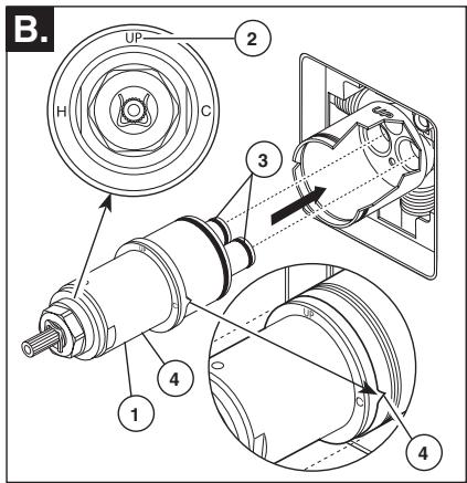
text_image
B. UP 2 H C 3 4 1 4Rotate the cartridge (1) so the word "UP" (2) appears on the top. Insert cartridge into valve body as shown. Make sure the cartridge tubes and O-rings (3) are properly seated in holes at the base of the body. Ensure the keys on the body are fully engaged with the slots in the body (4).
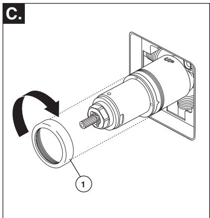
text_image
C. 1Slide bonnet nut (1) over the cartridge and thread onto the body. Hand tighten securely.
Back to back Installation
text_image
Normal Installation (changes not required) Reverse Installation Cold HotFor back to back or reverse installations (hot on right and cold on left): Rotate cartridge (1) so the word "UP" (2) appears on the bottom. Install the cartridge making sure that the keys are fully engaged with the slot in the brass body (see step B). Slide bonnet nut (3) over the cartridge and thread onto the body. Hand tighten securely.
17T Series Installation
2
Showerhead and Tub Spout Installation
text_image
A. 1 2 3 4FOR SHOWERHEAD INSTALLATION:
Connect top outlet (1) to shower arm (2) with proper fittings. To prevent damage to finish on shower arm, insert wall end of shower arm into shower flange (3) before screwing arm into riser connection. Thread showerhead (4) onto shower arm. Apply Teflon® tape to pipe threads on both ends. Do not overtighten showerhead.
FORTUB SPOUT INSTALLATION:
Refer to the installation instructions supplied with your spout. Do not connect deck mount spouts to in-wall valves. Do not use hand showers connected in lieu of a tub spout to a tub/shower valve. Do not use PEX tubing for tub spout drop.
text_image
B-1 2 1Slip-On Installation
The copper tube (1) must be 1/2" nominal copper. Important: If it is necessary to cut the copper tube, the end must be chamfered free of burrs to prevent cutting or nicking O-ring inside the spout. Slide spout over copper tube flush with the finished tub or wall surface. Tighten set screw (2), but do not overtighten.
text_image
B-2 1Iron Pipe Installation
Install threaded pipe nipple (1) to extend past finished wall. Apply Teflon® tape to threads on pipe nipple and screw on tub spout.
text_image
B-3 1 2 3Copper Sweat Installation
Remove O-ring (1) from adapter (2). Solder adapter to tube taking care to keep solder away from O-ring groove. CAUTION: NO SOLDER PERMITTED ON OUTSIDE DIAMETER OF ADAPTER ADJACENT TO O-RING GROOVE. Cut off tube (3) and replace O-ring on groove of brass adapter. Thread tub/spout onto adapter, taking care not to damage O-ring, and hand tighten until spout is firmly against finished wall and all slack is taken up behind wall.
3
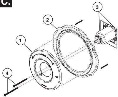
Valve Trim Installation
A.
text_image
Technical diagram of a mechanical device with labeled parts and directional arrows indicating motion or flow.Slide O-ring (1) over cartridge and the bonnet nut (2). The O-ring, which acts as a spacer to steady the sleeve, should rest behind the bonnet nut.
B.
natural_image
Technical diagram of a mechanical assembly with directional arrows indicating motion (no text or symbols present)Slide the sleeve (1) over the cartridge, body and O-ring. Ensure sleeve is properly positioned over the front of cartridge.
C.
text_image
Technical diagram of a mechanical assembly with numbered components and directional arrows indicating motion or flow.Secure the escutcheon (1) to the bracket (2) with the 2 screws provided (3). Do not overtighten escutcheon screws.
D.
natural_image
Technical line drawing of a mechanical assembly with a rotating component and a flanged base (no text or symbols)Install volume control handle (1) with lever to the right. DO NOT SECURE WITH SCREW.
17T Series Installation
4
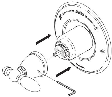
Installation and Adjustment of the Temperature Knob Failure to do so may cause injury.
text_image
Technical diagram of a mechanical device with numbered components for assembly or identification.Adjust temperature limit stop! Turn on water supplies; let the water run at both full hot and full cold to ensure the water is running as hot/cold as possible. Place a thermometer in a plastic tumbler, and hold the tumbler in the water stream. Place the temperature knob (1) onto the splines (2), then rotate the temperature knob until you achieve your maximum desired temperature from the outlet (not more
than 120^ or the lower temperature mandated by your local plumbing code). Remove the temperature knob and replace onto the splines (2), making sure that the temperature knob limit stop (3) hits against the volume handle limit stop (4) as shown. Secure volume handle with set screw (5). Secure the temperature knob using screw (6) and place cap (7) on knob.
Cleaning and Care
Care should be given to the cleaning of this product. Although its finish is extremely durable, it can be damaged by harsh abrasives or polish. To clean, simply wipe gently with a damp cloth and blot dry with a soft towel.
Warning: Scrubbing Bubbles® Bathroom Cleaner and Lysol® Basin Tub and Tile Cleaner must not be used on the clear knob handles and levers. Use of these cleaners can result in cracked or severely damaged handles. If overspray gets onto the handles, immediately wipe them dry with a soft cotton cloth
13/14 Series Maintenance
Faucet leaks from tub spout/showerhead:
SHUT OFF WATER SUPPLIES.
Replace seats and springs—Repair
Kit RP4993. Check condition of lower O-rings and replace if necessary RP14414. See Helpful Hints 1, 2, & 3.
If leak persists:
SHUT OFF WATER SUPPLIES.
Replace cap assembly RP46070 or valve cartridge RP46074.
See Helpful Hints 1, 2, 3 & 5.
Unable to maintain constant water temperature:
Replace housing assembly with RP46071 or follow instructions in Helpful Hints 1, 2, 4 & 5.
Helpful Hints:
- Before removing valve cartridge assembly for any maintenance, be sure to note the position of the rotational limit stop on the cap. The valve cartridge assembly must always be put back in the same position. BE SAFE! After you have finished the installation, turn on valve to make sure COLD WATER FLOWS FIRST.
- To remove valve cartridge from body, shut off water supplies and remove handle and bonnet nut. Do not pry the valve cartridge out of the body with
a screwdriver. Place handle on stem and rotate counterclockwise approximately 1/4 turn after the stop has been contacted. Lift valve cartridge out of body.
- To remove seats and springs, remove valve cartridge. Separate cap assembly from the housing assembly by rotating the cap assembly counterclockwise 90^ (degrees). Separate cap and housing assemblies. Remove seats and springs and replace. Place the largest diameter of the spring into the seat pocket first and then press the tapered end of the seal over the spring. Reassemble valve cartridge and replace in body following instructions given in 1 above.
- If the water in your area has lime, rust, sand or other contaminants in it, your pressure balance valve will require periodic inspection. The frequency of the inspection will depend on the amount of contaminants in the water. To inspect valve cartridge remove it and follow the steps in note 1 above. Turn the valve to the full mix position and shake the cartridge vigorously. If there is a rattling sound, the unit is functional and can be reinstalled following instructions given in note 1 above. If there is no rattle, replace the housing assembly (RP46071).
- Push disc until fully seated. See page 5 for more details.
17 Series Maintenance
Cannot receive more than a trickle of water:
Both hot and cold supply lines must be pressurized. If only one side is pressurized, the pressure balance system will not allow adequate flow of water.
Volume control handle rotates 360
degrees or is not positioned correctly per escutcheon, (sleeve is also loose). The keys of the cartridge have not been properly placed in the keyways in the brass body or keys on cartridge have been sheared off due to improper installation. BE SURE TO CORRECT THIS SITUATION IMMEDIATELY.
Cannot receive enough hot water:
See step 3 and/or check water heater temperature.
Faucet leaks from tub spout/showerhead:
SHUT OFF WATER SUPPLIES. Replace Adapter Assembly – Repair Kit RP46073.
If leak persists—
SHUT OFF WATER SUPPLIES
Replace cartridge assembly-RP46463.
Unable to maintain constant water temperature: SHUT OFF WATER SUPPLIES. Remove cartridge assembly, shake cartridge side to side. Spool should rattle in sleeve. If rattle cannot be heard, spool may be stuck. Spool may be freed up by rapping cartridge briskly sideways into the palm of your hand. If spool cannot be freed, replace cartridge assembly-RP46463.
NOTE: If the water in your area has lime, rust, sand, or other contaminants in it, your pressure balance valve will require periodic inspection. The frequency of the inspection will depend on the amount of contaminants in the water. To inspect cartridge, remove it from the body and shake it rigorously. If there is a rattling sound, the unit is functional and can be reinstalled in its previous position. If there is no rattle, replace the cartridge with RP46463.
17T Series Maintenance
Faucet leaks from showerhead or tub spout:
SHUT OFF WATER SUPPLIES. Replace Cartridge
Assembly – Repair Kit RP47201.
Cartridge Summary Reference Sheet
| Units shipped in March 2006 and after. | Units shipped before March 2006. | Replacement cartridges shipped in July 2006 and after. |
MultiChoice® 13/14 Order RP46074 to Replace Cartridge. Order RP46074 to Replace Cartridge. | OldMonitor® 1300/1400 Order RP19804 to Replace Cartridge. Order RP19804 to Replace Cartridge. | NewMonitor® 1300/1400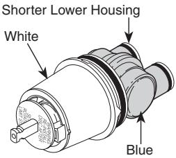 Order RP19804 to Replace Cartridge. Order RP19804 to Replace Cartridge. |
17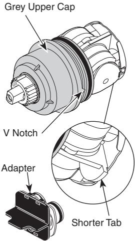 Order RP46463 to Replace Cartridge. Order RP46463 to Replace Cartridge. | 1700White Upper Cap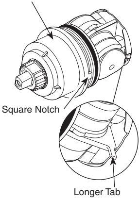 Order RP32104 to Replace Cartridge. Order RP32104 to Replace Cartridge. | NA |
| 17TBrassBlackOrder RP47201 to Replace Cartridge. |  Will Not Fit Will Not Fit |  |
MultiChoice® 13/14
Old Monitor® 1300/1400
New
Monitor® 1300/1400
NA
Delta Faucet Company
Product Service
55 E. 111th Street
Indianapolis, IN 46280
En Canada:
Masco Canada
Technical Service Centre
420 Burbrook Place
London, ON N6A 4L6
text_image
Exploded view diagram of a mechanical assembly with numbered parts for identificationtext_image
B. 1 2 3 4 5 HOTTER WARNING: NOT FOR SHORT SWEET ON ON ON ON ON ON ON ON ON ON ON ON ON ON ON ON ON ON ON ON ON ON ON ON ON ON ON ON ON ON ON ON ON ON ON ON ON ON ON ON ON ON ON ON ONnatural_image
Mechanical assembly diagram showing a rotating component with labeled parts (no text or symbols present)text_image
Technical diagram of a mechanical device with labeled components and directional arrows indicating motion or flow.text_image
Diagram showing mechanical assembly with gear and ring components labeled 1
text_image
Technical diagram of a mechanical assembly with labeled components and directional arrows indicating motion or flow.text_image
Technical diagram of a mechanical assembly with numbered components and directional arrows indicating motion or flow.text_image
Delta Machantext_image
Technical diagram of a mechanical device with labeled parts and directional arrows indicating motion or flow.natural_image
Technical diagram of a mechanical assembly with directional arrows indicating motion (no text or symbols)text_image
Technical diagram of a mechanical assembly with labeled components and directional arrowstext_image
Technical diagram of a mechanical assembly with numbered components and directional arrows indicating motion or assembly.text_image
Exploded view diagram of a mechanical component with numbered parts for identificationnatural_image
Mechanical assembly diagram showing a rotating component with a shaft and housing, labeled with number 1 (no text or symbols present)text_image
Diagram of a showerhead assembly with numbered parts and directional arrows indicating movement or forcePARA LAS INSTALACIONES DE LAS CABEZAS DE REGADERA: Conecte
text_image
Technical diagram showing a mechanical assembly with labeled parts 1 and 2, likely illustrating a valve or adjustment mechanism.B-2
natural_image
Technical line drawing of a mechanical component with no visible text or symbolsB-3
text_image
-3 1 3 2text_image
Technical diagram of a mechanical device with labeled parts and directional arrows indicating motion or flow.natural_image
Technical diagram of a mechanical device with labeled component 1, showing internal components and directional arrows (no text or symbols beyond labels)natural_image
Technical line drawing of a mechanical assembly with a tool and component (no text or symbols)text_image
Technical diagram of a mechanical device with numbered components for assembly or identification.Delta Faucet Company
Product Service
55 E. 111th Street
Indianapolis, IN 46280
Au Canada
Masco Canada
Technical Service Centre
420 Burbrook Place
London, ON N6A 4L6
© 2009 Division de Masco Indiana
text_image
Exploded view diagram of a mechanical assembly with numbered parts for identificationnatural_image
Mechanical assembly diagram showing a rotating component with a numbered label (1), no text or symbols present.text_image
Diagram showing a bell and its adjustment mechanism with numbered parts, likely illustrating a mechanical or electrical setup.INSTALLATION DE LA POMME DE
text_image
Technical diagram of a mechanical device with labeled components and directional arrows indicating motion or flow.text_image
Diagram showing mechanical assembly with gear and ring components labeled 1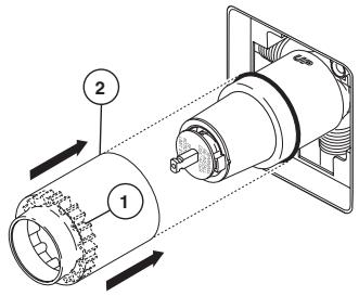
text_image
Technical diagram of a mechanical assembly with labeled components and directional arrows indicating motion or flow.text_image
Technical diagram of a mechanical assembly with numbered components and directional arrows indicating motion or flow.text_image
Delta Machantext_image
Exploded view diagram of a mechanical assembly with numbered parts for identificationtext_image
Technical diagram of a mechanical assembly with numbered components and directional arrows indicating motion or assembly.text_image
Diagram showing a bell and three labeled parts of a showerhead assembly with numbered componentsINSTALLATION DE LA POMME DE
text_image
Technical diagram showing a mechanical assembly with labeled parts 1 and 2, likely illustrating a valve or actuator mechanism.B-2
natural_image
Pure technical diagram of a mechanical component without any text, numbers, or symbolsB-3
text_image
Technical diagram of a mechanical device with numbered components labeled 1, 2, and 3.text_image
Technical diagram of a mechanical device with labeled parts and directional arrows indicating motion or flow.natural_image
Technical diagram of a mechanical assembly with directional arrows indicating motion (no text or symbols)text_image
Technical diagram of a mechanical assembly with labeled components and directional arrowstext_image
Exploded diagram of a washing machine with numbered parts for identificationnatural_image
Technical diagram of a mechanical device with a rotating shaft and housing, showing no text or symbols.text_image
Technical diagram showing a showerhead assembly with numbered components and directional arrows indicating flow or movement.INSTALLATION DE LA POMME DE
text_image
Technical diagram showing a mechanical assembly with labeled parts 1 and 2, likely illustrating a valve or adjustment mechanism.B-2
text_image
2 1B-3
text_image
-3 1 3 2text_image
Technical diagram of a mechanical device with labeled parts and directional arrows indicating motion or flow.natural_image
Technical diagram of a mechanical device with labeled component 1, showing internal components and directional arrows (no text or symbols beyond labels)natural_image
Technical line drawing of a mechanical assembly with a tool and component (no text or symbols)text_image
Technical diagram of a mechanical device with numbered components for assembly or identification.T13090, T13091, T13290, T13291, T13490 & T13491
natural_image
Simple line drawing of a curved, elongated object resembling a stylized shoe or container (no text or symbols)RP5833▲ Tub Spout/Non Diverter Tubo de Salida para Bañera/ Sin Desviador Bec/Sans Dérivation
RP17453 RP17454▲ (Metal/Metálico/Métal) Tub Spout/Pull-Down Diverter Tubo de Salida para Bañera/ Desviador de Halar Bec/Avec Dérivation sur Embout
natural_image
Simple line drawing of a mechanical component with no text or symbolsnatural_image
Simple line drawing of a funnel-shaped object with a circular top (no text or symbols)RP53237▲
Tub Spout/Non Diverter
Bec/Sans Dérivation
natural_image
Simple line drawing of a curved, irregular shape resembling a stylized bone or organic form (no text or symbols)† Designates the accent color on split finish models.
natural_image
Simple line drawing of a curved object resembling a tool or device (no text or symbols)natural_image
Technical line drawing of a mechanical component with a cylindrical body and flange (no text or symbols)O-Ring Anillo "O" Joint Torique
Handle Assembly Ensemble de la Manija Poignée
Decal (Red/Blue) Etiqueta (Rojo/Azul) Etiquette (Rouge/Bleu)
Screw/Tornillo/Vis
NOTE: Do NOT overtighten screw.
natural_image
Technical line drawing of a showerhead with no text or symbolsShowerhead
Cabeza de Regadera
Pomme de Douche
natural_image
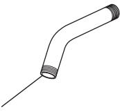
Simple line drawing of a bent pipe or tube with no text or symbolsRP40593▲
Shower Arm
Brazo de Regadera
Tuyau de Pomme de Douche
RP38452▲
Shower Flange
Collerette
natural_image
Line drawing of a mechanical component with a pointed tip and base, no text or symbols present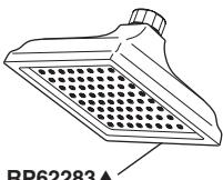
natural_image
Technical line drawing of a showerhead with grid pattern (no text or symbols)RP62283▲
Showerhead
Cabeza de Regadera
Pomme de Douche
Shower Arm
Brazo de Regadera
Tuyau de Pomme de Douche
RP6023▲
natural_image
Simple line drawing of a bent pipe or tube with threaded ends (no text or symbols)RP52144▲
Shower Flange
Pestaña de la Regadera
Collerette

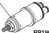
★ RP47201
Cartridge Assembly
Cartucho
Cartouche
natural_image
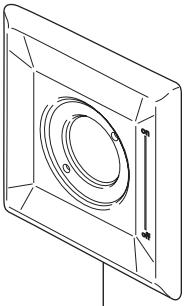
Technical line drawing of a square frame with a circular recess and mounting holes (no text or symbols)RP52583▲
Escutcheon
(Diag. Screw Holes)
Chapetón
(Huecos para los
Tornillos Diagonales)
Rosace
(Trous de Vis
en Diagonale)
Trim Sleeve
Manga de Franja
Manchon de Finition
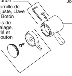
Set Screw,
Wrench &
Button —
Tornillo de
Ajuste, Llav
y Botón
Vis de
calage,
Clé et
Bouton
O-Ring
Anillo "O"
Joint Torique
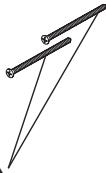
Trim Screws
Atornillos de Franja
Vis de Finition
For Longer Screws
Para Tornillos Más Grandes
Pour Vis Plus Longues
RP50879▲
RP52384
RP23336
RP196▲
RP12630▲
text_image
Ornillo de juste, Llave Botón is de alage, lé et outonRP52584▲
Handle Assembly
Ensemble de la Manija
Poignée
Tub Spout/Pull-Up Diverter
Tubo de Salida para Bañera/
Botón Desviador de Alzar
Bec/avec dérivation à tirette
RP52148▲
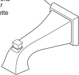
natural_image
Technical line drawing of a mechanical bracket or support structure (no text or symbols)natural_image
Simple line drawing of a curved pipe fitting with a knob (no text or symbols)Delta Faucet Company
Product Service
55 E. 111th Street
Indianapolis, IN 46280