CD5 - CD Player NAIM - Free user manual and instructions
Find the device manual for free CD5 NAIM in PDF.
| Product type | CD player |
| Brand | NAIM |
| Model | CD5 |
| Power supply | Mains (230V, 50Hz), 13A fuse (UK), compatible with external power supplies Flatcap 2, Hi-cap, Supercap |
| Supported formats | Audio CD, HDCD (automatic decoding) |
| Loading mechanism | CD drawer with magnetic platter and puck (CC3) |
| Controls | Previous, Next, Stop, Play buttons; NARCOM 3 and Flash remote controls |
| Display | Alphanumeric, track/time display, HDCD, pause, time, repeat, program indicators |
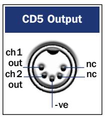
| Audio outputs | Main DIN (recommended), phono sockets (selectable via remote control) |
| Connectivity | DIN, phono, RC5 input for multiroom control |
| Playback functions | Play, pause (static after 10 min), track programming, repeat, random play, fast search |
| Power supply upgrade | External power supply possible (Flatcap 2, Hi-cap, Supercap) via 5-pin DIN cable |
| Maintenance and cleaning | Clean platter and puck with Blu-tack, do not use solvents |
| Safety | Mandatory earthing, do not open without disconnecting mains, disconnect before connections, lightning risk |
| Break-in instructions | Requires break-in (up to 5 weeks) for optimal performance |
| Multi-function mode | Selectable by holding Next/Previous at power on |
| Puck compatibility | Use only the provided puck (reference CC3 for CD5) |
| Certifications | Compliant with EMC and safety standards, FCC part 15 |
| Warranty | Unauthorized modifications void warranty |
| Transport | Two transport screws to remove before use and replace before shipping |
Frequently Asked Questions - CD5 NAIM
User questions about CD5 NAIM
0 question about this device. Answer the ones you know or ask your own.
Ask a new question about this device
Download the instructions for your CD Player in PDF format for free! Find your manual CD5 - NAIM and take your electronic device back in hand. On this page are published all the documents necessary for the use of your device. CD5 by NAIM.
USER MANUAL CD5 NAIM
Naim Audio products are always conceived with performance as the top priority and careful installation will help ensure that their full potential is achieved. This manual begins with statutory safety warnings and general installation tips for all Naim Audio products. Product specific information begins in Section 6.
1 Equipment Installation
Normally your Naim equipment will have been installed by the dealer who sold it to you even if you live outside their immediate vicinity. Your dealer is responsible for making sure that the system sounds exactly as it should and information given here is not intended to reduce this responsibility in any way.
2 Cables and Connections
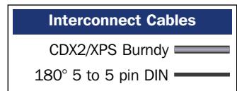
Please do not modify the standard interconnect cables supplied with your Naim equipment. This is important for safety as well as performance. One end of each cable is marked with a band to establish its correct orientation. The band always marks the end that connects to the signal source.
Loudspeaker leads are also very important. Naim loudspeaker cable is correct for your system and your dealer will make up leads to suit your equipment installation. The leads should each be at least 3.5 metres long and of equal length. The recommended maximum is 20 metres. Loudspeaker leads are, like interconnect leads, directional, and should be connected so that the printed arrow points towards the speakers. Using alternative loudspeaker cable will degrade performance, and may even damage your amplifier. An exception to these loudspeaker cable constraints is the NAP 6-50 multi-room power amplifier. The NAP 6-50 is designed to be tolerant of both a wide variety of cable types, and cable runs well in excess of 20m. The loudspeaker connectors supplied with all Naim amplifiers and loudspeakers have been specifically designed to make a robust mechanical connection. It is essential that these are used in order to comply with current European safety regulations.
All the plugs and sockets supplied with your Naim equipment have been chosen because they make the best possible connection for their purpose. A poor contact will degrade the signal substantially and plugs and sockets should look clean and free from corrosion. The easiest way to clean them is to switch off the equipment, pull the plugs out of their sockets, and push them back in again. Special contact cleaners and contact enhancers should not be used as they tend to deposit a film which is very difficult to remove and may degrade the sound.
3 Getting Started
CONTENTS
Page Section
1 1 Equipment Installation
1 2 Cables and Connections
1 3 Getting Started
3.1 switching on and off
3.2 running in
2 3.3 mains supply
3.4 siting the equipment
3.5 if you have a problem
2 4Warnings
3 5 Connection
5.1 mains lead
5.2 mains plugs
5.3 fuse carrier
5.4 plug fuses
4 6 CDS3 Installation and Operation
6 7 CDS3 Rear Panel and Connection Diagrams
7 8 CDS3 Operation Diagrams
9 9 CDX2 Installation and Operation
11 10 CDX2 Rear Panel and Connection Diagrams
12 11 CD5 Installation and Operation
13 12 CD5 Rear Panel and Connection Diagrams
14 13 CDX2/CD5 Operation Diagrams
16 14 Puck Identification.
17 15 Flash Handset
19 16 Narcom 3 Handset
21 Standards Declaration
3.1 switching on and off
Source components and power supplies for cd players, tuners, preamplifiers and crossovers should be switched on before switching on the power amplifier(s). Always switch the amplifier(s) off and wait about a minute for the power supply capacitors to discharge before connecting or disconnecting any leads. Always use the power switch on the product rather than a mains outlet switch.
3.2 running in
Your Naim equipment will take a considerable time to run in before it performs at its best. The duration varies, but under some conditions you will find that the sound continues to improve for as much as five weeks. Better and more consistent performance will be achieved if the system is left switched on for long periods. It is worth remembering however that all electronic equipment can be damaged by lightning. Please read the warnings section.
3.3 mains supply
Where fused plugs are used 13 amp fuses should be fitted. Fuses of a lower rating will fail after a period of use.
A hi-fi system usually shares a mains circuit with other household equipment some of which can cause distortion of the mains waveform. In some Naim equipment such distortion can lead to a mechanical hum from the transformers. The hum is not transmitted through the speakers and has no effect on the performance of the system but is purely local to the transformer itself. A separate fused mains circuit (like that reserved for electric cookers) may reduce transformer hum. Such a circuit (ideally with a 30 or 45 Amp rating) will also have a lower impedance, supply cleaner power, and consequently improve system performance.
Do not wire voltage dependent resistors or noise suppressors into mains plugs. They degrade the mains supply and the sound.
IMPORTANT
In order to comply with current European safety regulations it is essential that the Naim loudspeaker connectors supplied with amplifiers and loudspeakers are used.
Do not under any circumstances allow anyone to modify your Naim equipment without first checking with the factory, your dealer, or your distributor. Unauthorized modifications will invalidate your guarantee.
For your own safety do not under any circumstances open Naim equipment without first disconnecting the mains.
The following label is attached to all mains powered equipment:
WARNING
THIS APPARATUS
MUST BE EARTHED
3.4 siting the equipment
Power supplies and amplifiers should be located a reasonable distance away from other equipment. This separation will stop transformer radiation causing hum audible from the loudspeakers. The maximum separation distance for connected equipment is that allowed by the standard interconnect lead.
Some Naim equipment is extremely heavy. Ensure that your equipment rack or table can easily support the weight and is stable.
3.5 if you have a problem
Legal consumer protection varies from country to country. In most territories a dealer must be prepared to take back any Naim equipment he has sold you if he cannot make it work to your satisfaction in your own home. A problem may be due to a fault in any part of the system or its installation so it is essential to make full use of your local dealer's diagnostic skills on site. Please contact your local distributor, or Naim at the address in the back of this manual, if any difficulties cannot be resolved. Some Naim equipment is made in special versions for different territories and this makes it impracticable to arrange international guarantees. Please establish the guarantee arrangements with your own dealer at the time of sale. We are always available to offer help and advice.
It is essential that repairs and updates are only carried out by an authorised Naim dealer, or at the factory by Naim itself. Many components are made, tested or matched specially for Naim and appropriate replacements are often unobtainable from non-specialist sources.
4Warnings
Naim equipment is designed to offer the finest sound quality that can be achieved avoiding compromise wherever possible. This can lead to circumstances that may be unfamiliar. The material that follows contains advice specifically related to Naim equipment as well as more general warnings about the use of domestic audio products. Please read it carefully.
The transformers in Naim power amplifiers and power supplies may sometimes make a mechanical noise caused by distortion of the mains waveform. Naim transformers are large in size and have heavy gauge secondary windings making them relatively sensitive to such distortion. A separate mains circuit for your hi-fi system may reduce the effect while also giving an overall improvement in sound quality. It may be necessary however to take account of mechanical transformer noise when siting your equipment.
In some circumstances, depending on where you live and the earthing arrangements in your home, you may experience radio frequency interference. Controls on broadcasting in some territories allow very high levels of radio frequency radiation and both the choice and exact siting of equipment may be critical. If there is a known problem in your locality it is advisable to arrange for a home demonstration before purchase to find out if Naim equipment is likely to be affected. Susceptibility to radio frequency interference is related to the wide internal bandwidth necessary for high sound quality. Systems incorporating moving coil phono preamplifiers and active crossovers are more likely to suffer. A radio frequency filter kit is available for some Naim equipment but sound quality will be progressively compromised as more elements of the kit are fitted. In situations of extreme radio interference Naim equipment may be unsuitable.
Your Naim hi-fi system can be damaged by lightning. Power amplifiers are particularly at risk and should be turned off when there is risk of lightning strike. For complete protection all mains plugs and any aerial cables should be disconnected when not in use.
Equipment must not be exposed to dripping or splashing and no objects filled with liquid, such as vases, should be placed on the equipment.
Use of non-standard speaker cables or interconnects may invalidate your guarantee.
5 Connection
5.1 mains lead
As the colours of the wires in the mains lead of this apparatus may not correspond with the coloured markings identifying the terminals in your plug proceed as follows:
The wire which is coloured GREEN-AND-YELLOW must be connected to the terminal in the plug which is marked by the letter E or by the safety earth symbol or coloured green or green-and-yellow.
The wire which is coloured BLUE must be connected to the terminal in the plug which is marked with the letter N or coloured black.
The wire which is coloured BROWN must be connected to the terminal in the plug which is marked with the letter L or coloured red.
5.2 non-rewireable mains plugs
If a non-rewireable plug is cut from a mains lead (for whatever purpose) the plug MUST be disposed of in a way to render it totally useless. Considerable shock hazard exists if the cut-off plug is inserted into a mains outlet.
5.3 fuse carrier
Should the plug fuse carrier be damaged or lost, the correct replacement must be obtained from your dealer, or from Naim Audio direct. Do not use the plug until the fuse carrier is replaced.
5.4 plug fuses
Replace only with ASTA or BS 1362 approved fuses.
NOTE
This equipment has been tested and found to comply with the relevant EMC and Safety Standards, and, where applicable, also complies with the limits for a class B digital device, pursuant to Part 15 of the FCC Rules.
These limits are designed to provide reasonable protection against harmful interference in a residential installation. This equipment generates, uses and can radiate radio frequency and, if not installed and used in accordance with the instructions, may cause harmful interference to radio communications. However, there is no guarantee that interference will not occur in a particular installation. If this equipment does cause harmful interference to radio or television reception, which can be determined by turning off and on, the user is encouraged to try to correct the interference by one or more of the following measures:
- Reorient or relocate the receiving antenna.
- Increase the separation between the equipment and the receiver.
- Connect the equipment into an outlet on a circuit different from that to which the receiver is connected.
- Consult your Naim dealer or an experienced radio/TV technician for help.
CDS3
6 Installation and Operation
The CDS3 CD Player can only be operated from a Naim XPS Power Supply. Connection of the power supply is illustrated in Diagram 7.2
The CDS3 should be installed on a dedicated equipment stand intended for the purpose. To improve sound quality the player has hard metallic feet which may blemish any delicate surface on which it is placed. Do not stand the player directly on top of another item of Naim Audio equipment. Care should be taken to ensure that the player is level.
Transit screws on the underside of the CDS3 case and beneath its transport lid should be removed before use and must be replaced if the unit is to be moved or re-packed and shipped. The transit screw locations are illustrated in Section 8.1. The transit screws must not be used in any other Naim product. Do not invert the player once the transit screws are removed.
6.1 disc loading
Disc loading is illustrated in Section 8.2. To load a compact disc lift the transport lid from the front of the player. Place the disc on the platter followed by the magnetic puck. Do not use a puck from any other Naim CD player. Different Naim CD players use dissimilar pucks. The illustration in Section 14 will help identify the correct puck for the CDS3.
If an HDCD® encoded compact disc is loaded the CDS3 will automatically recognise and decode it. The display will read HDCD for a few seconds after play is pressed.
6.2 player controls
previous: With a disc loaded but not playing the previous button searches the disc contents backwards, either one track at a time, or sequentially if the button is held. While a disc is in play, the previous button searches the table of contents backwards. Play resumes with the selected track when the button is released.
next: The next button operates in the same way as the previous button, but moving forwards through the disc instead of backwards.
stop: Stops play and resets the player to its start condition. Pressing and holding stop will clear any programmed play order, or, if no play order is programmed, return the player display to its default state (track indication).
play: Plays a disc from track one unless another track has been selected. Play operated while a track is playing will re-start the track.
pause: Pauses play. Pressing pause a second time will resume replay. If play is selected while the player is paused, replay will resume at the start of the paused track when pause is deselected. The pause button indicator will flash when pause is selected.
If the CDS3 is paused for more than 10 minutes it will enter a "static pause" mode in which the transport laser deactivates and the disc stops spinning - so reducing wear on the transport. The player can be left in static pause indefinitely. The pause button indicator will illuminate fully rather than flash when the player is in static pause mode.
Pressing the pause button will deselect static pause. Replay will resume at the pause point.
display: Scroll through the display options of "track", "time" and display off.
All CD control functions are duplicated on the NARCOM 3 and Flash remote handsets. The handsets also provide CD programming facilities. See Sections 15 and 16 for more information.
6.3 front panel control mode selection
The CDS3 has an optional front panel control mode. This multi-function mode provides an alternative front panel interface in which fast forward and fast reverse can be selected by pressing and holding next and previous respectively.
To select multi function mode press and hold next while the player switches on. To select the standard control mode press and hold previous while the player switches on.
6.4 player display and indicators
The alphanumeric display indicates track and index numbers, time in minutes and seconds, or various system messages (Error, Track programming info, etc). The full stop on the right of the display window illuminates when the player receives a signal from the remote handset. If a track play list is programmed the time displayed reflects the duration of the program. Above the display are four indicators.
HDCD: Illuminates to show that an HDCD encoded disc is playing.
time: Illuminates to indicate display of total disc time or elapsed time of track being played.
repeat: Illuminates to show that repeat has been selected from the remote handset.
Illuminates to indicate that a program has been stored. Further information on play list programming can be found in Sections 15 and 16
6.5 output socket selection
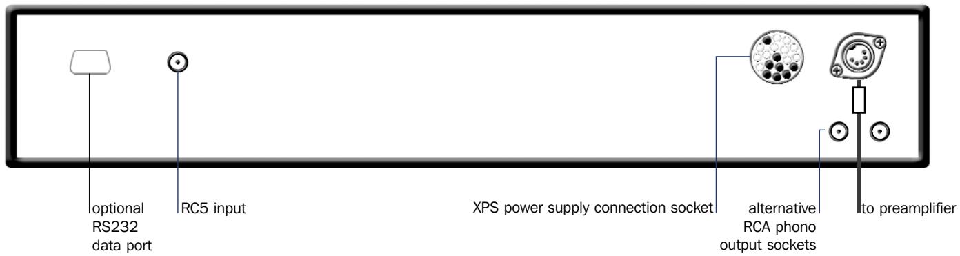
A pair of phono output sockets are fitted at the rear of the CDS3 to provide an alternative to the preferred DIN socket. Proceed as follows to select the phono sockets.
With the player stopped, press and hold the remote handset disp function (handset in CD mode) or front panel disp button until the CD player prog indicator flashes. Further operations of the disp function will now cycle through each combination of the two socket types (DIN only, phono only or both). The selected option is indicated on the CD player display as shown below.
Socket Option
Player Display
DIN
0
Phono
00
Both
0 00
Press and hold the disp function a second time to exit from socket selection mode.
6.6 player maintenance
It is important for reliable operation of the CDS3 to ensure that the surfaces of the transport platter and the underside of the puck are free of dust or debris which can prevent the disc from sitting properly and cause it to slip.
To clean the transport platter, take a piece of Blu-tack and lightly apply it to the top surface of the magnetic metal hub, picking up any material attached to it. Brush the plastic outer edge lightly with your finger or a soft brush to ensure that it is dust and particle free. Similarly, clean the puck with Blu-tack, to remove debris from the three locating pins on its underside. Take care not to damage the rubber pressure pads. Brush them lightly with your finger or a soft cloth.
Do not, under any circumstances, use any solvents or fluids for the cleaning process.
7.1 CDS3 Rear
Note
The RC5 input fitted to the CDS3 is intended to accept external control signals for multi-room applications. Contact your dealer for further information on its use.
7.2 CDS3 Connected to XPS Power Supply

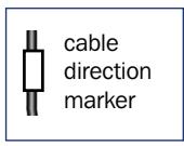
cable
direction
marker
Interconnect Cables
CDS3/XPS Burndy
180^5 to 5 pin DIN
CDS3 Operation
8.1 Transit Screws
Remove the four underside transit screws (keep safe). Always replace them before moving or shipping the player.
Do not invert the player for this operation or once the transit screws are removed.
Remove the two cd transport transit screws (keep safe). Always replace them before moving or shipping the player.
Do not invert the player once the transit screws are removed.

CDS3 Operation
8.2 CD Loading
9 Installation and Operation
The CDX2 CD Player can be operated either from its internal power supply or, for improved performance, from an external Naim XPS Power Supply. Connection of the power supply is illustrated in Diagram 10.2
The CDX2 should be installed on a dedicated equipment stand intended for the purpose. To improve sound quality the player has hard metallic feet which may blemish any delicate surface on which it is placed. Do not stand the player directly on top of another item of Naim Audio equipment. Care should be taken to ensure that the player is level.
A transit screw on the underside of the CDX2 case should be removed before use and must be replaced if the unit is to be re-packed and shipped. This transit screw must not be used in any other Naim product. The transit screw location is illustrated in Diagram
13.1. Do not invert the player once the transit screw is removed.
9.1 disc loading
Disc loading is illustrated in Section 13.2. To load a compact disc pull open the CD drawer using the handle on the left hand side of the player. Place the disc on the platter followed by the magnetic puck. Do not use a puck from any other Naim CD player. Different Naim CD players use dissimilar pucks. The illustration in Section 14 will help identify the correct puck for the CDX2.
If an HDCD® encoded compact disc is loaded the CDX2 will automatically recognise and decode it. The display will read HDCD for a few seconds after play is pressed.
9.2 player controls
previous: With a disc loaded but not playing the previous button searches the disc contents backwards, either one track at a time, or sequentially if the button is held. While a disc is in play, the previous button searches the table of contents backwards. Play resumes with the selected track when the button is released.
next: The next button operates in the same way as the previous button, but moving forwards through the disc instead of backwards.
stop: Stops play and resets the player to its start condition. Pressing and holding stop will clear any programmed play order, or, if no play order is programmed, will return the player display to its default state (track indication).
play: Plays a disc from track one unless another track has been selected. Play operated while a track is playing will re-start the track.
All CD control functions are duplicated on the NARCOM 3 and Flash remote handsets. The handsets also provide CD programming facilities. See Sections 15 and 16 for more information.
9.3 front panel control mode selection
The CDX2 has an optional front panel control mode. This multi-function mode provides an alternative front panel interface in which fast forward, fast reverse and pause are selected by pressing and holding next, previous and play respectively.
To select multi function mode press and hold next while the player is switched on. To select the standard control mode press and hold previous while the player is switched on.
9.4 player display and indicators
The alphanumeric display indicates track and index numbers, time in minutes and seconds, or various system messages (Error, Track programming info, etc). The full stop on the right of the display window illuminates when the player receives a signal from the remote handset. If a track play list is programmed the time displayed reflects the duration of the program. On the far left of the display are five indicators.
HDCD: Illuminates to show that an HDCD encoded disc is playing.
pause: Flashes to show that pause has been selected from the remote handset.
Note: If the CDX2 is paused for more than 10 minutes it will enter a "static pause" mode in which the transport laser deactivates and the disc stops spinning - so reducing wear on the transport. The player can be left in static pause indefinitely. The pause indicator will illuminate fully rather than flash when the player is in static pause mode.
time: Illuminates to indicate display of total disc time or elapsed time of the track being played.
repeat: Illuminates to show that repeat has been selected from the remote handset.
Illuminates to indicate that a program has been stored. Further information on play list programming can be found in Sections 15 and 16.
9.5 output Socket Selection
A pair of phono output sockets are fitted at the rear of the CDX2 to provide an alternative to the preferred DIN socket. Proceed as follows to select the phono sockets.
With the player stopped, press and hold the remote handset disp function (handset in CD mode) until the CD player prog text indicator flashes. Further operations of the disp function will now cycle through each combination of the two socket types (DIN only, phono only or both). The selected option is indicated on the CD player display as shown below.
Socket Option Player Display
| DIN | 0 |
| Phono | 00 |
| Both | 000 |
Press and hold the disp function a second time to exit from socket selection mode.
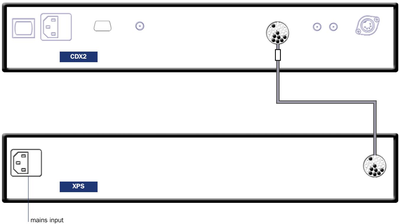
9.6 power supply upgrade
The CDX2 can be upgraded by the addition of an XPS Power Supply. The XPS takes over from the internal power supply of the CDX2 and offers both a greater number of separate supplies and more sophisticated voltage regulation.
The XPS is connected to the CDX2 via a heavy duty "Burndy" cable. Switch off both the XPS and CDX2 when making connections. Remove the CDX2 mains cable. Connect the Burndy cable ensuring that the connectors are securely attached and their twist lock mechanisms are engaged. Switch on the XPS from its front panel power button. After a short while the CDX2 will function as normal.
9.7 player maintenance
It is important for reliable operation of the CDX2 to ensure that the surfaces of the transport platter and the underside of the puck are free of dust or debris which can prevent the disc from sitting properly and cause it to slip.
To clean the transport platter, take a piece of Blu-tack and lightly apply it to the top surface of the magnetic metal hub, picking up any material attached to it. Brush the plastic outer edge lightly with your finger or a soft brush to ensure that it is dust and particle free. Similarly, clean the puck with Blu-tack, to remove debris from the three locating pins on its underside. Take care not to damage the rubber pressure pads. Brush them lightly with your finger or a soft cloth.
Do not, under any circumstances, use any solvents or fluids for the cleaning process.
10.1 CDX2 Rear
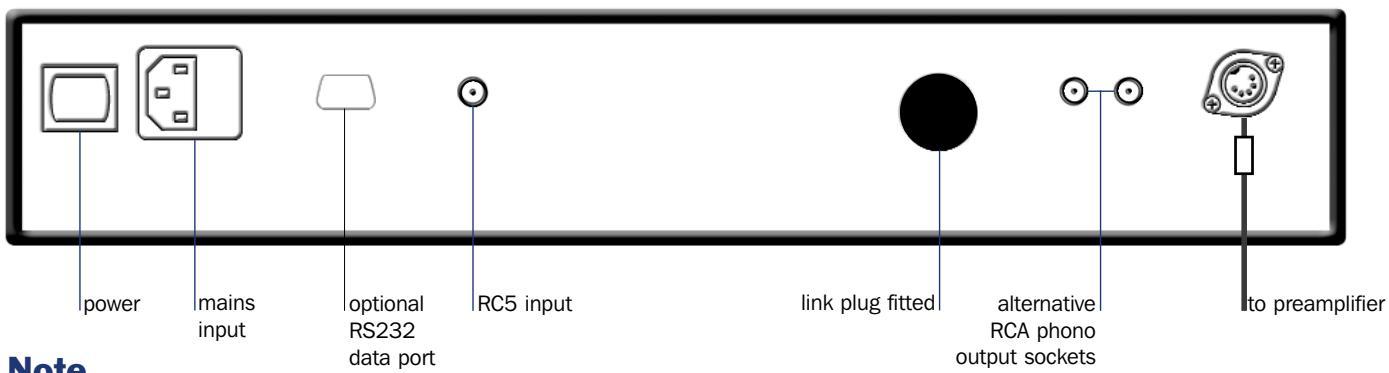
The RC5 input fitted to the CDX2 is intended to accept external control signals for multi-room applications. Contact your dealer for further information on its use.
10.2 CDX2 Connected to XPS Power Supply
Note
When used with an XPS the CDX2 must be disconnected from the mains. Always switch off the CDX2 when connecting or disconnecting an XPS.
11 Installation and Operation
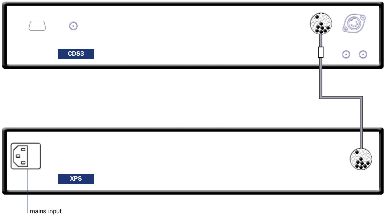
The CD5 CD Player can be operated either from its internal power supply alone or, for improved performance, with an additional external Supercap, Hi-cap or Flatcap 2 Power Supply. Connection of a Flatcap 2 is illustrated in Diagram 12.2
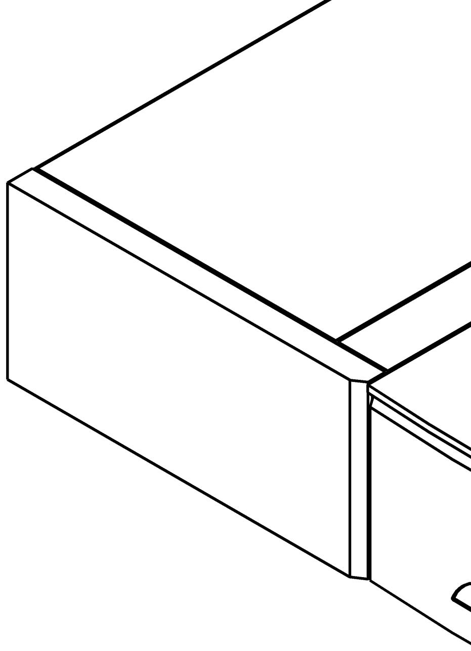
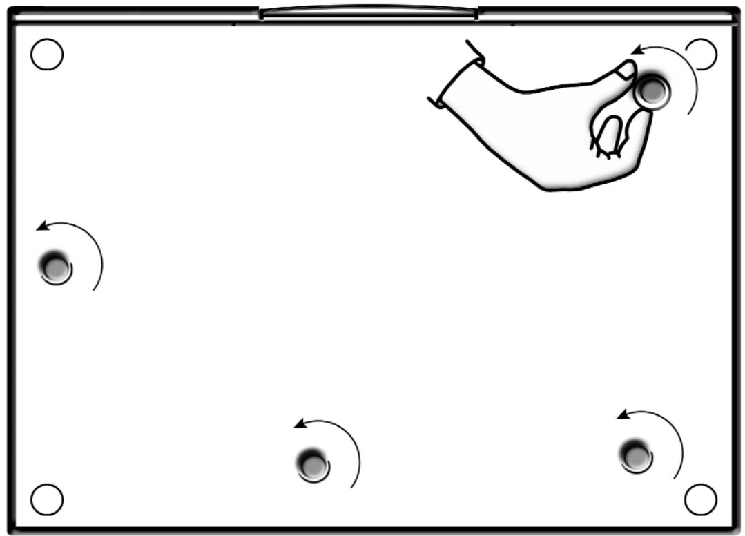
The CD5 should be installed on a dedicated equipment stand intended for the purpose. Care should be taken to ensure that the player is level. Two transit screws on the underside of the CD5 case should be removed before use and must be replaced if the unit is to be re-packed and shipped. These transit screws must not be used in any other Naim product. The transit screw locations are illustrated in Diagram 13.1.
11.1 disc loading
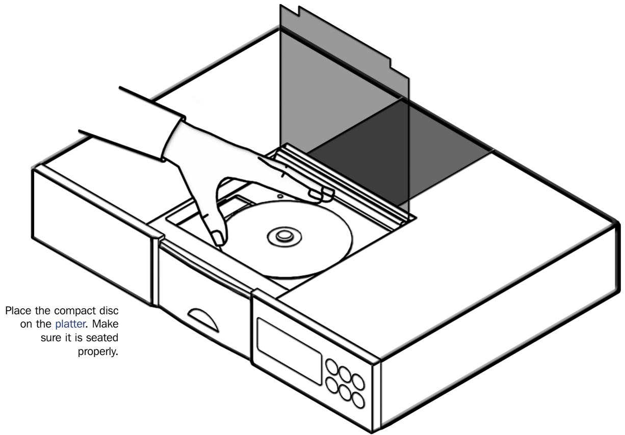
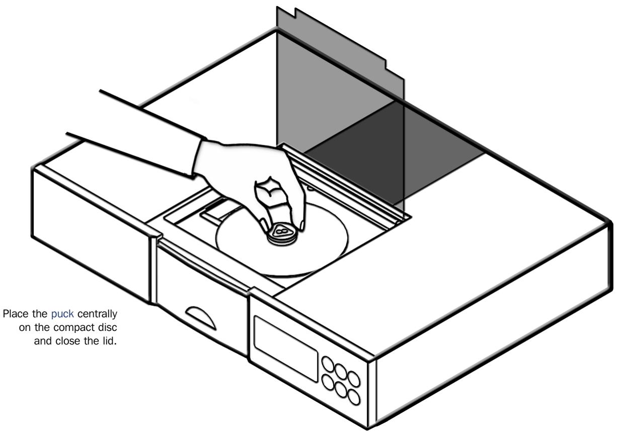
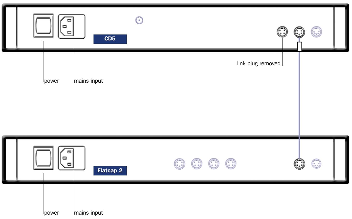
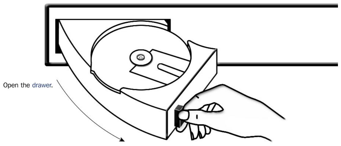
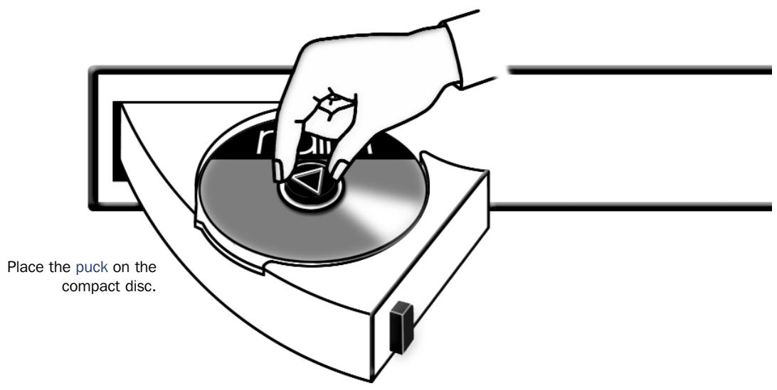
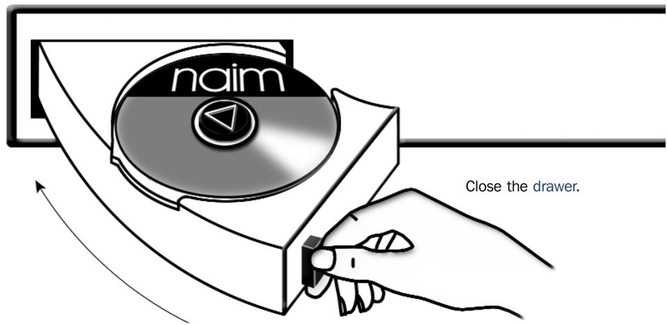
Disc loading is illustrated in Section 13.2. To load a compact disc pull open the CD drawer using the handle on the left hand side of the player. Place the disc on the platter followed by the magnetic puck. Do not use a puck from any other Naim CD player. Different Naim CD players use dissimilar pucks. The illustration in Section 14 will help identify the correct puck for the CD5.
11.2 player controls
previous: With a disc loaded but not playing the previous button searches the disc contents backwards, either one track at a time, or sequentially if the button is held. While a disc is in play, the previous button searches the table of contents backwards. Play resumes with the selected track when the button is released.
next: The next button operates in the same way as the previous button, but moving forwards through the disc instead of backwards.
stop: Stops play and resets the player to its start condition.
play: Plays a loaded disc from track one unless another track has been selected. The play button operated while a track is playing will restart that track.
All CD control functions are duplicated on the NARCOM 3 and Flash remote handsets. The handsets also provide CD programming facilities. See Sections 15 and 16 for more information.
11.3 front panel control mode selection
The CD5 has an optional front panel control mode. This multi-function mode provides an alternative front panel interface in which fast forward, fast reverse and pause are selected by pressing and holding next, previous and play respectively.
To select multi function mode press and hold next while the player is switched on. To select the standard control mode press and hold previous while the player is switched on.
11.4 player display and indicators
The alphanumeric display indicates track and index numbers, time in minutes and seconds, or various system messages. The full stop on the right of the display window illuminates when the player receives a signal from the remote handset. On the far left of the display are four indicators.
pause: Illuminates to show that pause has been selected from the remote handset.
time: Illuminates to indicate display of total disc time or elapsed time of track being played.
repeat: Illuminates to show that repeat has been selected from the remote handset.
prog: Illuminates to indicate that a program has been stored. Further information on play list programming can be found in Sections 15 and 16.
11.5 power supply upgrade
The CD5 can be upgraded through the addition of an external Power Supply. The external supply works with the internal power supply of the CD5 to offer both a greater number of separate supplies and more sophisticated voltage regulation. The Power Supply is connected to the CD5 via a five pin DIN cable. Switch off both the Power Supply and CD5 when making connections. Connect the supply cable ensuring that the connectors are securely attached. Switch on both the CD5 and the Power Supply from their respective power buttons.
11.6 player maintenance
It is important for reliable operation of the CD5 to ensure that the surfaces of the transport platter and the underside of the puck are free of dust or debris which can prevent the disc from sitting properly and cause it to slip.
To clean the transport platter, take a piece of Blu-tack and lightly apply it to the top surface of the magnetic metal hub, picking up any material attached to it. Brush the plastic outer edge lightly with your finger or a soft brush to ensure that it is dust and particle free. Similarly, clean the puck with Blu-tack, to remove debris from the three locating pins on its underside. Take care not to damage the rubber pressure pads. Brush them lightly with your finger or a soft cloth. Do not, under any circumstances, use any solvents or fluids for the cleaning process.
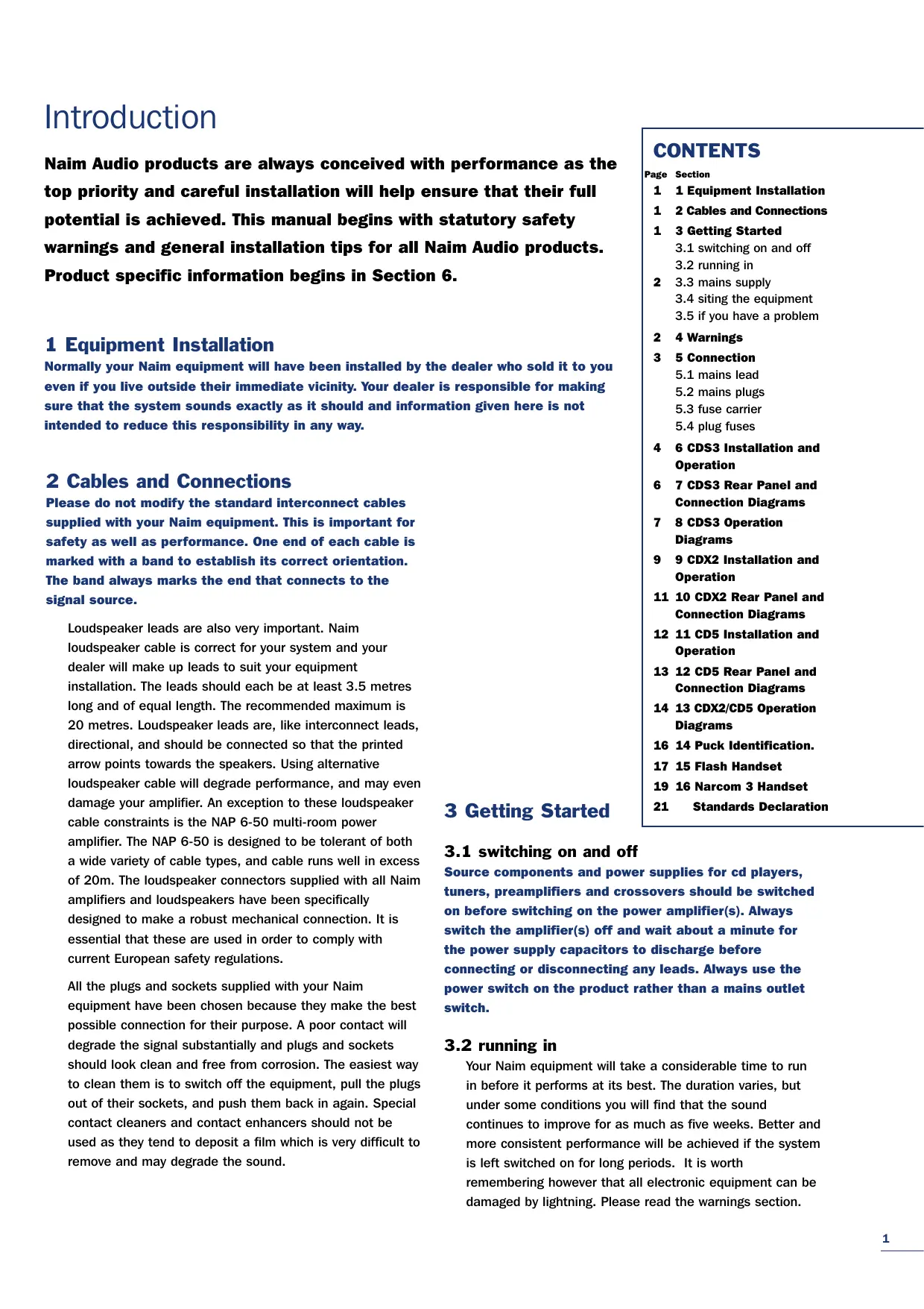
12.1 CD5 Rear
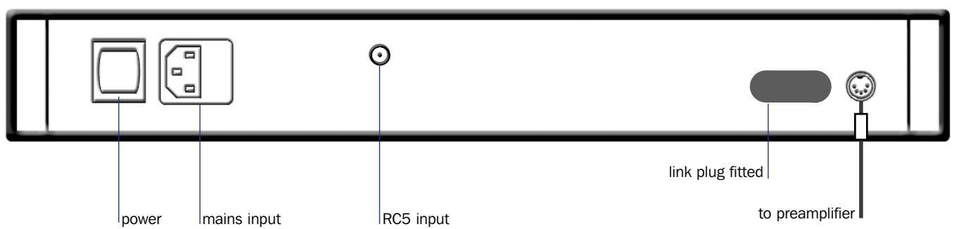
Note
The RC5 input fitted to the CD5 is intended to accept external control signals for multi-room applications. Contact your dealer for further information on its use.
The CD5 features various technologies to reduce microphonic effects, in particular a compliant mounting for the main circuit boards and the DIN sockets on the rear. Some movement of the board and sockets when connecting/disconnecting is normal.
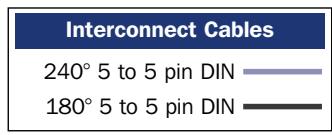
12.2 CD5 Connected to Flatcap 2 Power Supply
CDX2/CD5 Operation
13.1 Transit Screw
Remove and retain the transit screw(s). One on the CDX2, two on the CD5. Always replace the screws before transit or shipping.
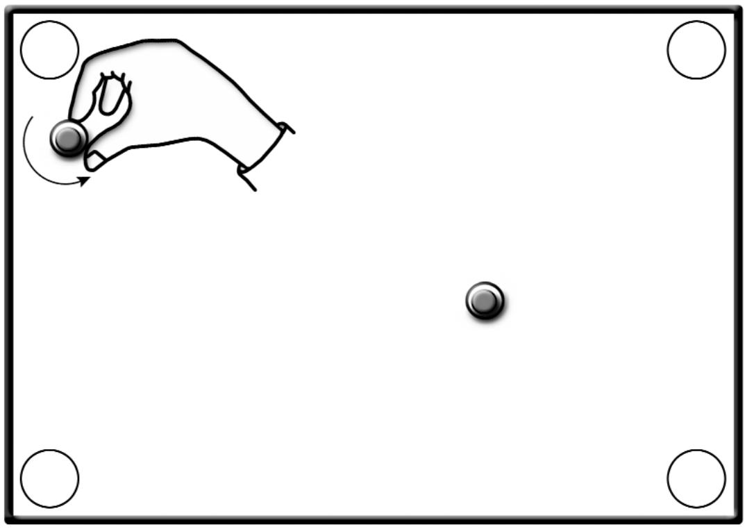
13.2 CD Loading
CDX2/CD5 Operation
Place the compact disc on the platter. Make sure it is seated properly.

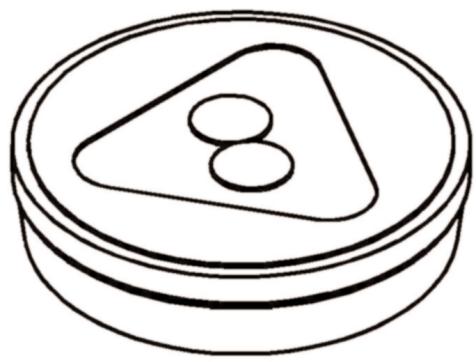
CD Puck Identification
14.1 Puck 3
Naim Part No:
CC3
CD Transport Compatibility:
VAM1205
CD Player Compatibility:
CDS2, CDX, CD5
14.2 Puck 4
Naim Part No:
CC4
CD Transport Compatibility:
VAM1250
CD Player Compatibility:
CDS3, CDX2
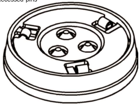
Recessed pins


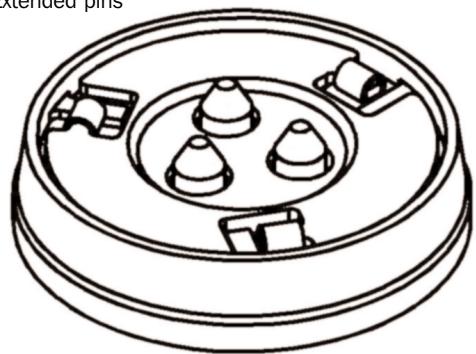
Extended pins

Flash Handset
15.1 Introduction
Flash is factory pre-programmed to operate any Naim preamplifier or cd player, the NAT 05 tuner and AV2 audio-visual processor. Additional Naim sources may be catered for in the future. Contact your dealer or local representative for information.
Flash is supplied without batteries fitted. To fit the batteries, remove the battery cover with the supplied hexagon driver and slide the batteries into the handset body taking care with their orientation. Replace the battery cover. Do not over-tighten the fixing screw. With batteries fitted the handset is ready for use. Flash is designed to switch off if unused after 10 seconds. It switches on immediately if it is moved or a key is pressed.
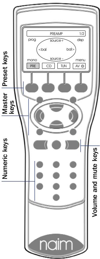
15.2 using Flash
Flash can be set to control each equipment type through the four preset keys beneath the display. The selected equipment mode is indicated in the display above each preset key. When a preset key is pressed the display and the eight master keys and the numeric keys will reconfigure appropriately. The display for each equipment type shows a representation of the eight master keys and their functions.
The AV preset key will also wake an av processor from standby. Press and hold the AV preset key to return the processor to standby mode.
The volume up and down and
mute keys are always
available to control the
appropriate (audio-visual or preamplifier) volume and mute functions regardless of the selected source equipment mode.
The Preamplifier, CD, and AV equipment modes have multiple display "pages" (only one page is necessary for Tuners). The first display page of each provides control of the most commonly used functions, with subsequent pages generally providing access to those less often used. Selection of second and third pages within each mode is made by pressing the appropriate preset key. The currently selected page is shown in the top right corner of the display. Details of the master key functions within each page is described in the following paragraphs:
PRE (preamplifier mode)
Page 1 of 2
source + Selects the next input source.
source - Selects the previous input source.
<bal Adjusts balance to the left.
bal> Adjusts balance to the right.
prog Enters programming mode on preamplifiers.
disp Selects display options on appropriately equipped preamplifiers.
mono Sums the left and right channels.
Note: On Naim preamplifiers with no mono facility, operates the tape monitor function.
menu Accesses a Flash setup page where source
labels can be chosen, and display preferences can be set. Also provides access to RC5 setup.
numeric Directly selects preamplifier input channels.
Page 2 of 2
The master key functions on PRE Page Two are duplicates of Page One. However, selection of Page Two provides control of the record functions on appropriately equipped preamplifiers.
CD (cd mode)
Page 1 of 2
play Begins cd play
stop Stops cd play
prev Selects the previous track or index point
next Selects the next track or index point
pause Pauses cd play
disp Cycles the cd player display through track, time and off options.
rev Fast reverses cd
fwd Fast forwards cd
numeric Directly select CD tracks.
Page 2 of 2
The master key functions play, stop, prev, next, rev and fwd on CD Page Two are duplicates of Page One. However, selection of Page Two provides programming and repeat functions.
prog Enters CD track programming mode.
rep Repeats the CD or programmed tracks.
numeric Selects CD tracks or index points for programming.
Flash Handset
TUN (tuner mode)
Page 1 of 1
up Depending on the operational mode selected, adjusts the tuning frequency upwards (frequency mode), searches for stations up the FM band (scan mode) or selects the next station preset (preset mode).
down Controls the tuner in a similar manner to the up key.
prog Selects preset program mode that enables specific FM stations to be assigned to preset memory.
disp Switches the tuner display on or off.
mono Combines the left and right channels and may improve reception on weak signals.
mode Selects frequency, scan and preset modes.
numeric Directly select station presets.
AV (av processor mode)
Page 1 of 3
input+ Selects the next input.
input- Selects the previous input.
mode- Selects the previous decode mode.
mode+ Selects the next decode mode.
osd Selects On Screen Display operational mode and shows current system status.
disp Switches the processor display on and off.
midn Selects midnight operational mode.
menu Used in setup mode.
numeric Directly selects processor inputs.
Page 2 of 3
The master key functions on AV Page Two are duplicates of Page One. However, selection of Page Two switches the function of the numeric keys to direct selection of processor decode modes.
Page 3 of 3
up Selects the previous AV setup parameter or moves the OSD cursor upwards.
down Selects the next AV setup parameter or moves the OSD cursor downwards.
left Selects the previous AV parameter value or moves the OSD cursor to the left.
right Selects the next AV parameter value or moves the OSD cursor to the right.
input Switches the AV processor into input setup mode.
spkr Switches the AV processor into speaker setup mode.
enter Confirms option selection during OSD control.
clear Clears option selection during OSD control.
numeric No function.
15.3 cd track programming
In CD mode the prog key (display Page Two) enables specific CD tracks and their play order to be programmed.
To program a play order select a track number from the numeric keypad followed by the prog key until the desired selection is complete. During selection, the track number indicated in the player display will be followed by either P or -P indicates that the track is already selected, -P indicates that the track can be selected.
The prog key can also be used to delete tracks from a play order. To delete a track, press and hold the prog key until the prog indicator in the CD display illuminates then delete the track or tracks using the numeric keypad followed each time by a further operation of the prog key. During deletion the track number indicated in the player display will be followed by either or - or no display. indicates that the track is already deleted, - indicates that the track can be deleted while no display indicates that this is the only track remaining and therefore cannot be deleted.
The CD player can be programmed with a random play order (from stop with no play order already in place) by pressing prog followed by 1. Similarly, to program a reverse play order, press prog followed by 2.
Play orders can be reviewed by pressing prog while the player is either stopped or playing. The player display will then scroll through the selected tracks. The prog indicator on the player display will illuminate when a play order has been programmed. To clear the program memory press and hold the stop key.
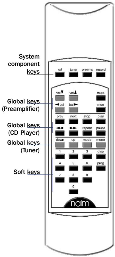
Narcom 3 Handset
16.1 Introduction
Narcom 3 is a multi-functional remote control handset designed to be used with Naim Audio CD players, integrated amplifiers, preamplifiers and preset tuners. The handset control configuration is based around three types of keys: System Component Keys, Global Keys and Soft Keys.
16.2 system component keys
These keys switch the operation of the Soft Keys into modes appropriate to each system component (CD, tuner, preamp, record).
cd: Switches the action of the Soft Keys to that appropriate for a CD player.
tuner: Switches the action of the Soft Keys to that appropriate for a preset tuner.
preamp: Switches the action of the Soft Keys to that appropriate for an integrated or preamplifier.
record: Switches the action of the Soft Keys to select record inputs on appropriately equipped preamplifiers.
16.3 Global Keys
These keys operate specific component functions regardless of the System Component Key setting.
Preamplifier
vol ( \& ) Modifies the preamplifier output volume and the volume control position.
mute Reduces the preamplifier output volume to zero. A second press restores the volume.
bal ( & ) Modifies the output channel balance. Some Naim amplifiers have control of balance available only from the remote handset. On these products the balance will automatically centre as it reaches the mid point. Balance centring is indicated by a flashing volume control indicator. To resume adjustment once the balance has centred, bal key must be released and re-pressed.
mon Enables the output of appropriately equipped tape machines to be heard while recording. The source to be recorded is chosen by the input selection buttons in the normal way. A second operation of the mon key restores normal operation.
Alternatively operates the mono function on appropriately equipped preamplifiers.
Compact Disc
prev Selects the previous track or index point.
next Selects the next track or index point.
stop Stops cd play.
play Begins cd play.
<<\&>> Fast reverses and fast forwards the cd. repeat repeats the cd or programmed tracks.
pause Pauses the cd.
Tuner
mode Switches the tuner sequentially through manual, scan and preset modes. Modes are indicated by the scan and preset indicators on the tuner display.
up & down These keys both have three possible functions depending upon the selection of the mode key. In manual mode the up and down keys adjust the tuning frequency in 0.1MHz steps. In scan mode the up and down keys will make the tuner search for stations. In preset mode the up and down keys will tune to the next numbered preset.
mono Toggles between mono and stereo operation. The tuner display will indicate stereo when both stereo operation is selected and a stereo signal is received. The mono button on the tuner will illuminate when mono is selected.
Narcom 3 Handset
16.4 soft keys
These keys operate functions depending on the System Component Key setting.
numeric keypad: In preamp mode the numeric keys will switch between the preamplifier inputs. In cd mode the numeric keys will select tracks. In tuner mode the numeric keys will select tuner presets or tuner frequency. In record mode the numeric keys will switch between record inputs on appropriately equipped preamplifiers.
16.5 cd track programming
In CD mode the prog key enables specific tracks and their play order to be programmed.
To program a play order select a track number from the numeric keypad followed by the prog key until the desired selection is complete. During selection, the track number indicated in the player display will be followed by either P or - or no display. P indicates that the track is already selected, - indicates that the track can be selected.
The prog key can also be used to delete tracks from a play order. To delete a track, press and hold the prog key until the prog indicator in the CD display illuminates then delete the track or tracks using the numeric keypad followed each time by a further operation of the prog key. During deletion the track number indicated in the player display will be followed by either or - or no display. indicates that the track is already deleted, - indicates that the track can be deleted while no display indicates that this is the only track remaining and therefore cannot be deleted.
The CD player can be programmed with a random play order (from stop with no play order already in place) by pressing prog followed by 1. Similarly, to program a reverse play order, press prog followed by 2.
Play orders can be reviewed by pressing prog while the player is either stopped or playing. The player display will then scroll through the selected tracks. The prog indicator on the player display will illuminate when a play order has been programmed. To clear the program memory press and hold the stop key.
In cd mode the disp key will scroll through these options: tracks ("time" indicator off), time ("time" indicator on) and display off.
Declaration of conformity to appropriate standards
Manufacturer
Naim Audio Limited, Southampton Road, Salisbury, England, SP1 2LN
Products
CDS3, CDX2, XPS, CD5
Safety
HD 195-S6
EN 60 065
EMC
Emissions Tested to:
Immunity Tested to:
In accordance with:
EN 55013 - Sound and television broadcast receivers and associated equipment
EN55020 - Electromagnetic immunity of broadcast receivers and associated equipment
CISPR 16-1 - Radio disturbance and immunity measuring apparatus
CISPR 16-2 Methods of measurement of disturbances and immunity
IEC 801-2 8KV (air gap) 4KV (contact) (performance criterion B)
IEC 801-3 3V/m 20dB (performance criterion A)
IEC 801-4 1KV (AC lines) 0.5KV (signal lines) (performance criterion B)
Acknowledgement
HDCD system manufactured under license from Pacific Microsonics, Inc. This product is covered by one or more of the following: US Pat No. 5479168, 5638074, 5640161, 5808574, 5838274, 5854600, 5864311, 5872531 Australia Pat No. 669114. Other patents pending.