
RSP-985 - Audio Preamplifier ROTEL - Free user manual and instructions
Find the device manual for free RSP-985 ROTEL in PDF.
| Product type | Surround sound preamplifier |
| Brand | ROTEL |
| Model | RSP-985 |
| Dimensions (W × H × D) | 440 × 121 × 329 mm |
| Weight | 7.0 kg |
| Power supply | 115 V / 60 Hz (USA version) or 230 V / 50 Hz (Europe version) |
| Power consumption | 46 W |
| Total harmonic distortion (10 Hz - 70 kHz) | < 0.03 % |
| Signal-to-noise ratio (IHF "A" weighted) | 100 dB (stereo) / 90 dB (Dolby Digital, DTS) |
| Frequency response (audio) | 20 Hz - 20 kHz, ± 1 dB |
| Frequency response (video) | 3 Hz - 10 MHz, ± 3 dB |
| Audio inputs | 6 RCA inputs (CD, Tuner, Video 1-4) + optical digital input (Tuner, Video 4) and coaxial (CD, Video 1-3) + 5.1 channel input (DB25) |
| Audio outputs | 6 preamp RCA outputs (front L/R, center, surround L/R, subwoofer) + DB25 output + Video 2-4 recording outputs + Zone 2 output |
| Video inputs | Composite RCA and S-Video (6 inputs) |
| Video outputs | Composite RCA and S-Video (monitor + recording) |
| Supported surround formats | Dolby Pro Logic, Dolby Digital, DTS, THX Ultra, DSP modes (Music 1-4) |
| Main functions | Motorized volume control, independent listen/recording input selection, Zone 2, on-screen display (OSD), universal remote control RR-939 |
| Cleaning | Use a dry cloth or vacuum cleaner. Do not use liquid or abrasive products. |
| Safety | Do not expose to moisture, unplug if not used for an extended period, leave 10 cm of free space around the device for ventilation. |
| Spare parts / Reparability | No user-serviceable parts. Refer all servicing to qualified personnel. |
| General information | Manufactured under license from Dolby Laboratories. THX Ultra is a trademark of Lucasfilm. Designed for accurate sound reproduction in home cinema. |
Frequently Asked Questions - RSP-985 ROTEL
User questions about RSP-985 ROTEL
0 question about this device. Answer the ones you know or ask your own.
Ask a new question about this device
Download the instructions for your Audio Preamplifier in PDF format for free! Find your manual RSP-985 - ROTEL and take your electronic device back in hand. On this page are published all the documents necessary for the use of your device. RSP-985 by ROTEL.
USER MANUAL RSP-985 ROTEL
This symbol is to alert the user to the presence of uninsulated dangerous voltages inside the product's enclosure that may constitute a risk of electric shock.

This symbol is to alert the user to important operating and maintenance (service) instructions in this manual and literature accompanying the product.
WARNING:
There are no user serviceable parts inside. Refer all servicing to qualified service personnel.
WARNING:
To reduce the risk of fire or electric shock, do not expose the unit to moisture or water. Do not allow foreign objects to get into the enclosure. If the unit is exposed to moisture, or a foreign object gets into the enclosure, immediately disconnect the power cord from the wall. Take the unit to a qualified service person for inspection and necessary repairs.
Read all the instructions before connecting or operating the component. Keep this manual so you can refer to these safety instructions.
Heed all warnings and safety information in these instructions and on the product itself. Follow all operating instructions.
Clean the enclosure only with a dry cloth or a vacuum cleaner.
You must allow 10 cm or 4 inches of unobstructed clearance around the unit. Do not place the unit on a bed, sofa, rug, or similar surface that could block the ventilation openings. If the unit is placed in a bookcase or cabinet, there must be ventilation of the cabinet to allow proper cooling.
Keep the component away from radiators, heat registers, stoves, or any other appliance that produces heat.
The unit must be connected to a power supply only of the type and voltage specified on the rear panel of the unit.
Connect the component to the power outlet only with the supplied power supply cable or an exact equivalent. Do not modify the supplied cable in any way. Do not attempt to defeat grounding and/or polarization provisions. The cable should be connected to a 2-pin polarized wall outlet, matching the wide blade of the plug to the wide slot of the receptacle. Do not use extension cords.
Do not route the power cord where it will be crushed, pinched, bent at severe angles, exposed to heat, or damaged in any way. Pay particular attention to the power cord at the plug and where it exits the back of the unit.
The power cord should be unplugged from the wall outlet if the unit is to be left unused for a long period of time.
Immediately stop using the component and have it inspected and/or serviced by a qualified service agency if:
- The power supply cord or plug has been damaged.
- Objects have fallen or liquid has been spilled into the unit.
The unit has been exposed to rain. - The unit shows signs of improper operation
- The unit has been dropped or damaged in any way
Place the unit on a fixed, level surface strong enough to support its weight. Do not place it on a moveable cart that could tip over.

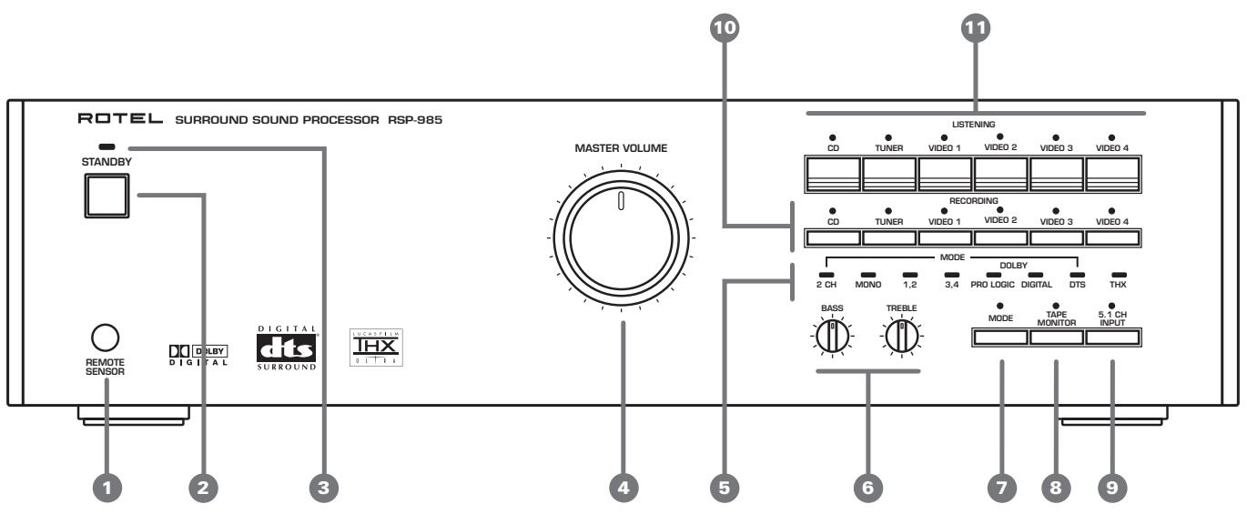
Figure 1 - Controls and Connections
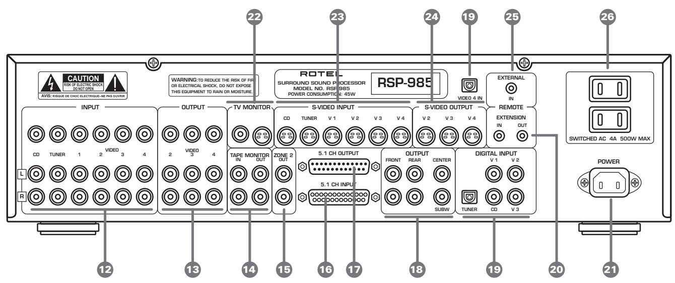
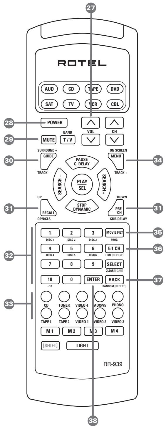
Figure 2 - Remote Control
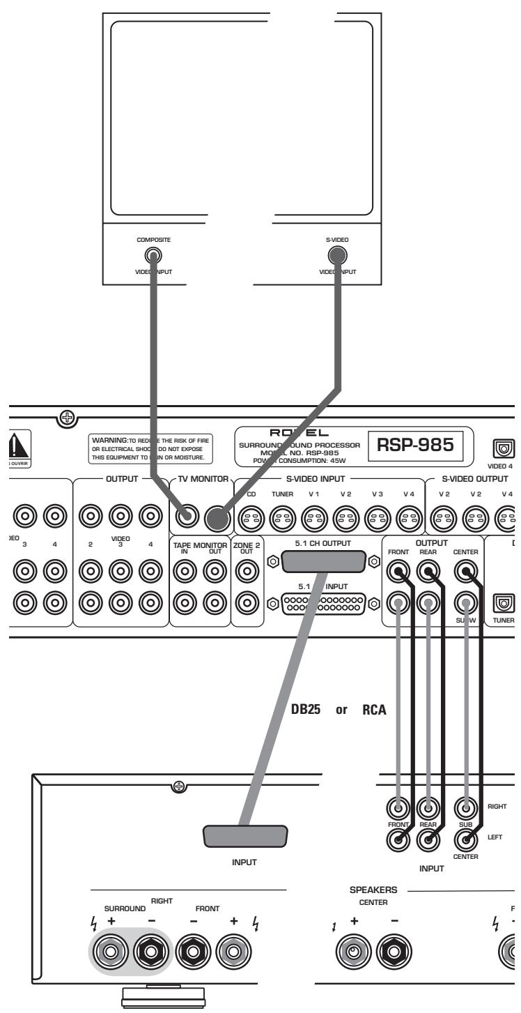
Figure 3 - Output Connections
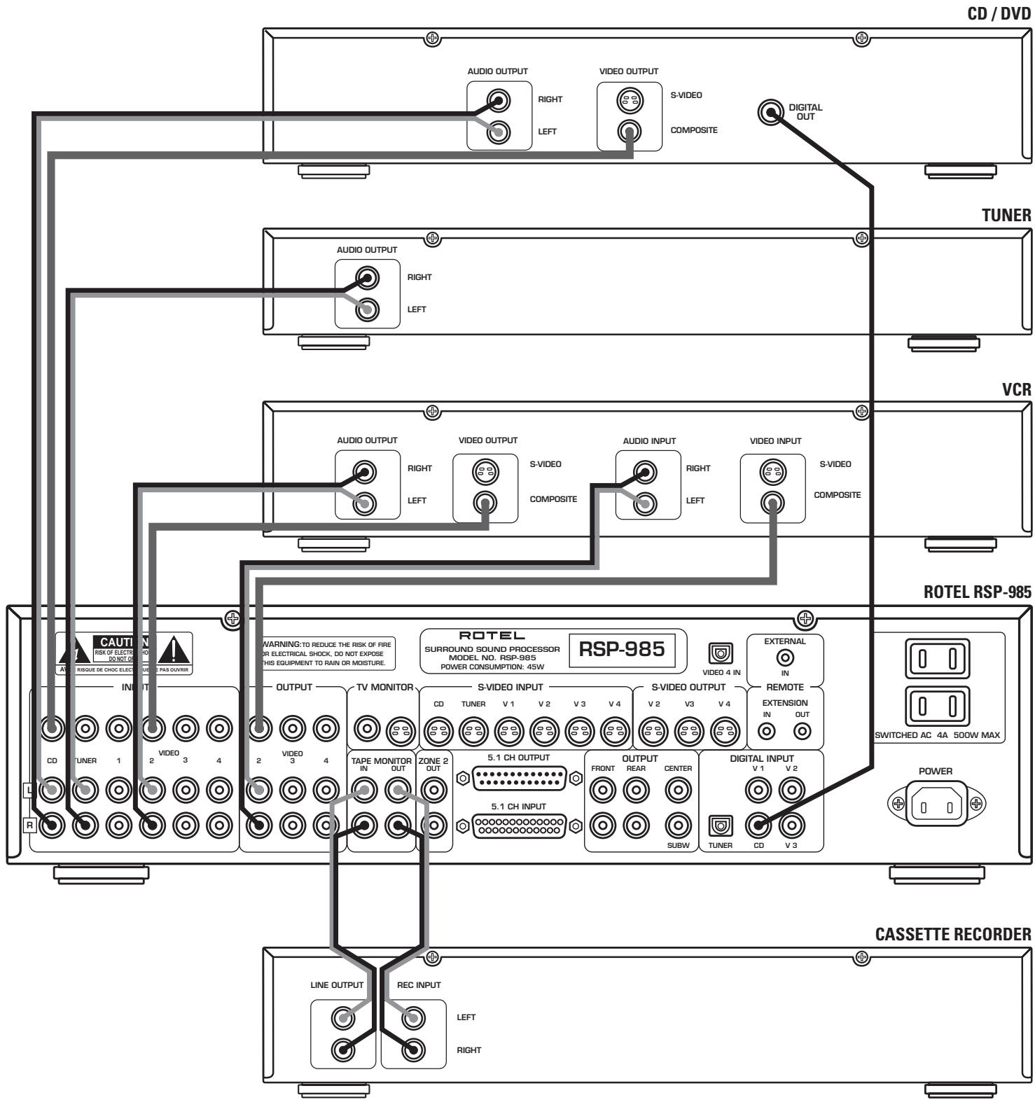
Figure 4 - RCA Source Connections
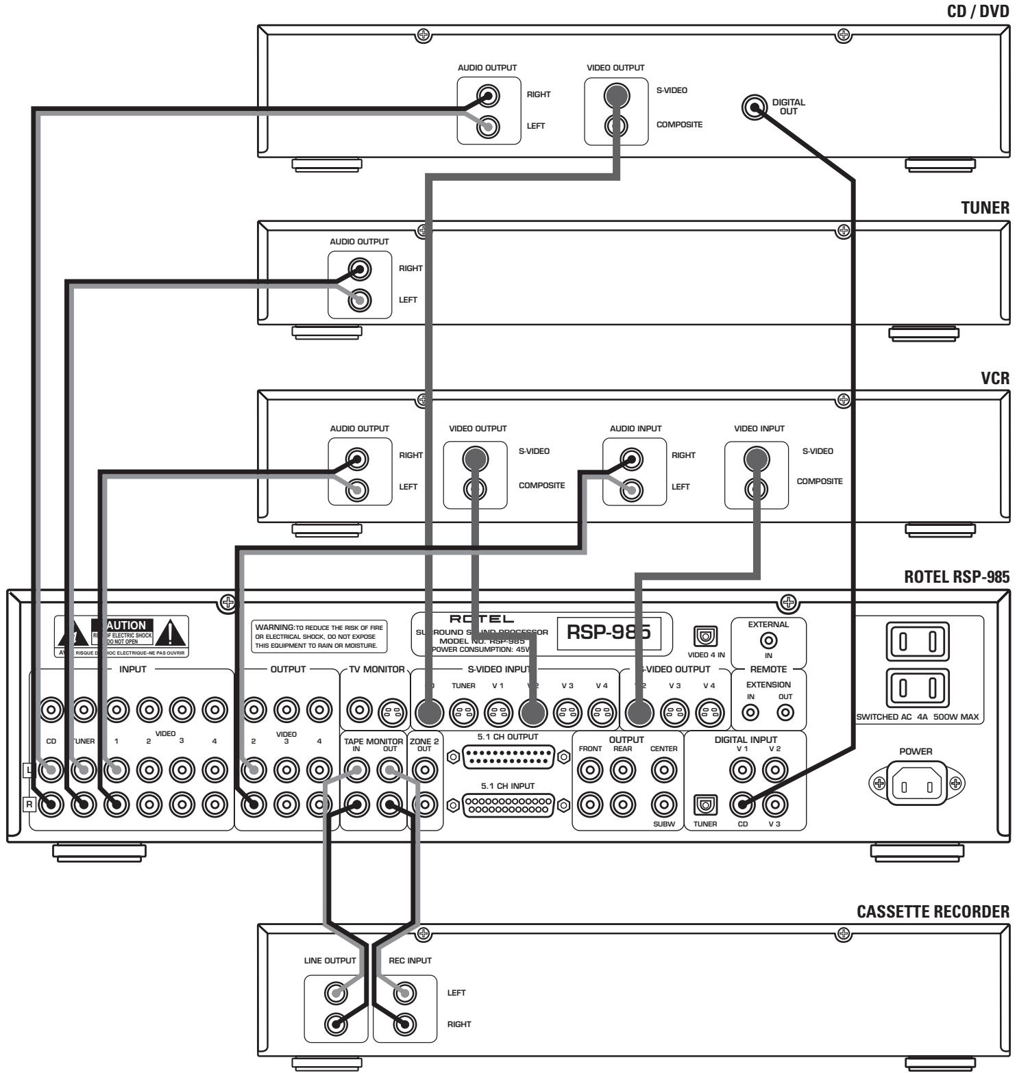
Figure 5 - S-Video Source Connections
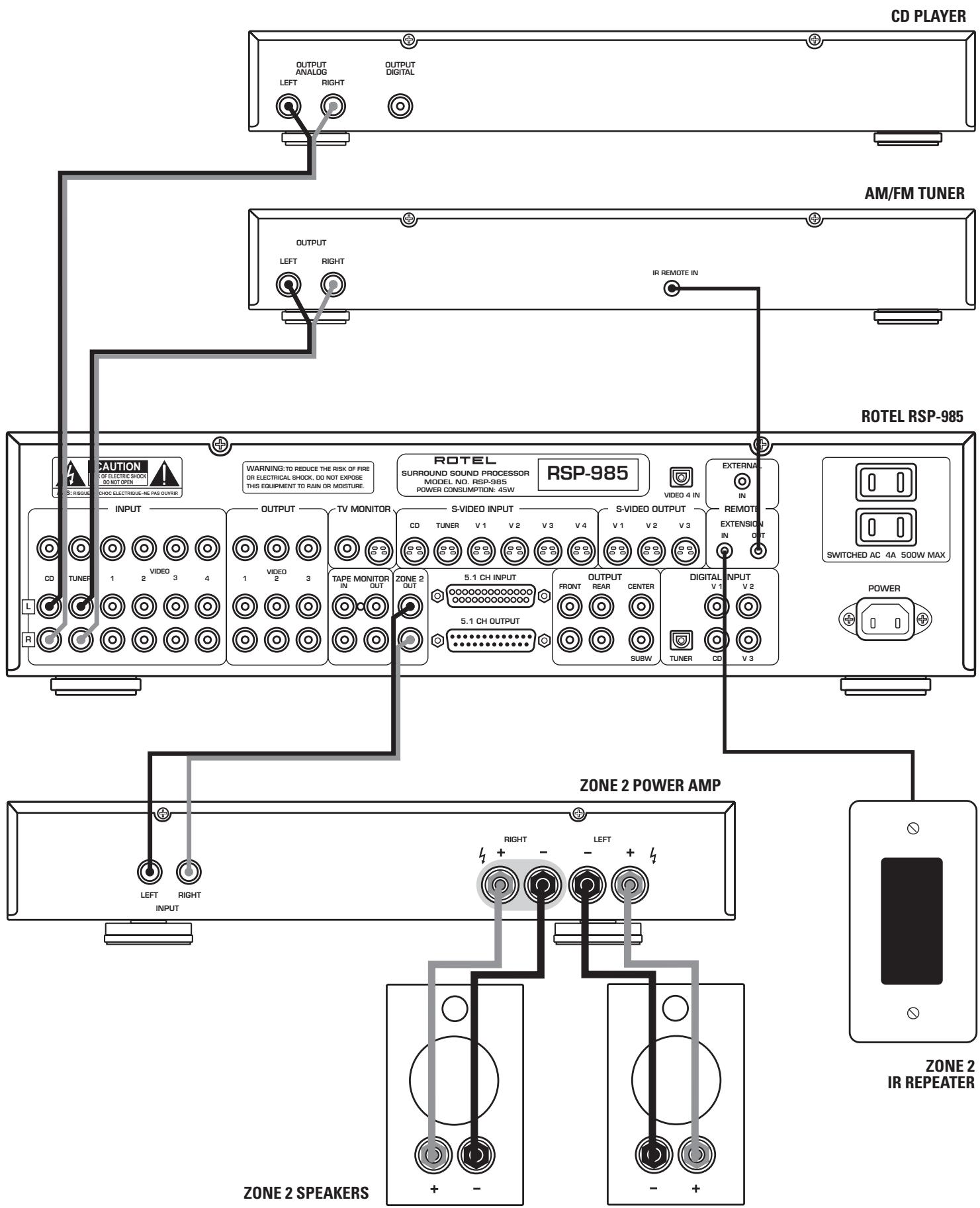
Figure 6 - Zone 2 Connections
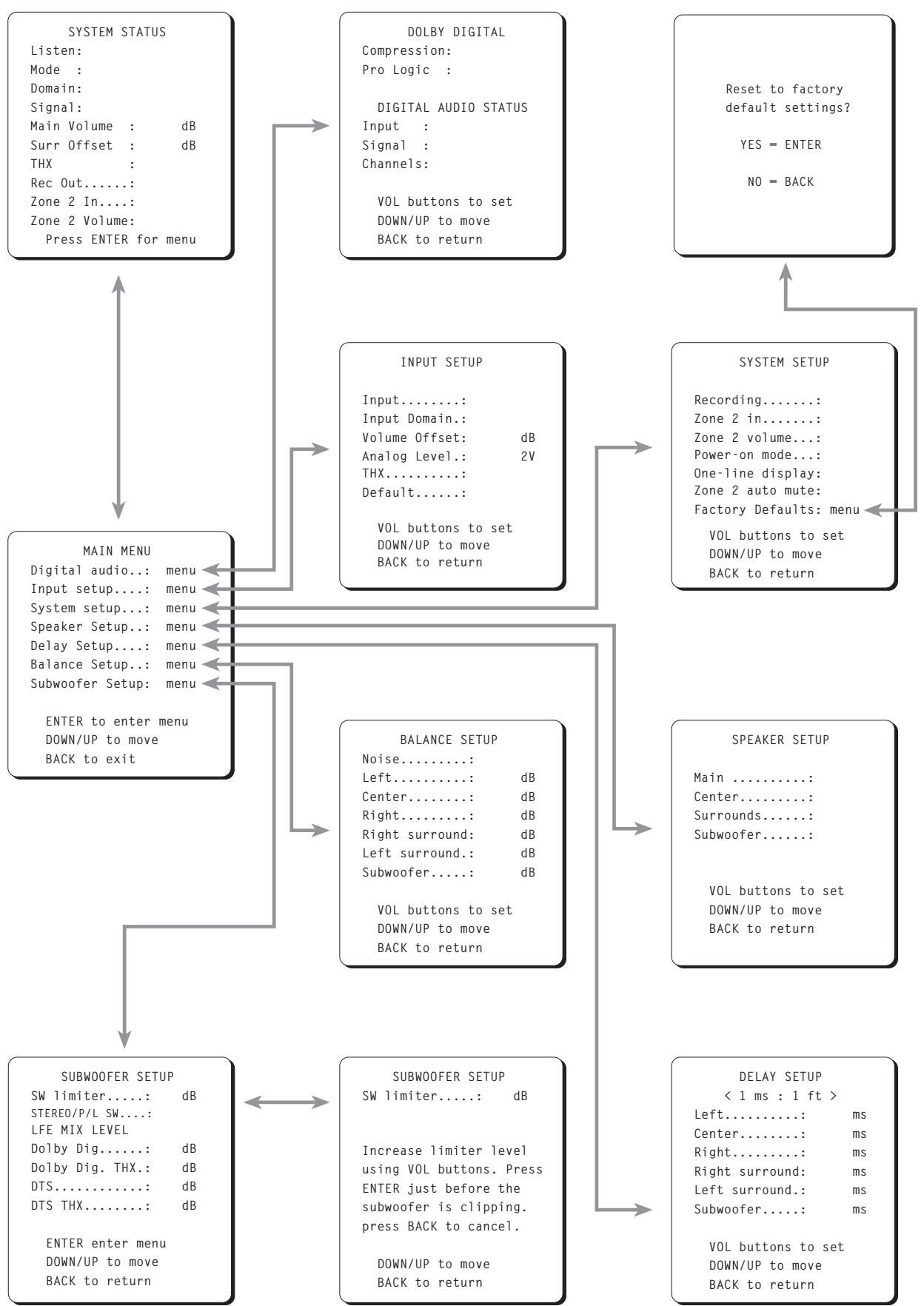
Figure 7 - On-Screen Menus
Contents
Figure 1-Controls and Connections 3
Figure 2 - Remote Control 4
Figure 3-Output Connections 4
Figure 4 - RCA Source Connections 5
Figure 5 - S-Video Source Connections 6
Figure 6-Zone 2 Connections 7
Figure 7 - On-Screen Menus 8
About Rotel 10
Getting Started 10
RSP-985 Key Features 10
About the THX UltraTM System 10
Unpacking the RSP-985 10
Placement 10
Front Panel Controls 11
Standby LED 3 11
Standby Switch 2 11
Remote Sensor 1 11
Master Volume Control 4 11
Tone Controls 6 11
Listening Input Source Buttons 11
5.1 Channel Input 12
Tape Monitor 8 12
Recording Input Source Buttons 10 12
Surround Sound Mode LEDs 12
Mode Button 7 13
RR-939 Remote Control 13
Programming the RR-939 13
Power Button 28 13
Volume Buttons 27 13
Mute Button (remote only) 29 14
Input Select Buttons 33 14
5.1 CH Button 36
Surround + Button 30 14
Movie Filter/THX (remote only) 35 14
Numeric Buttons (remote only) 14
On-Screen Button (remote only) 34 14
DOWN/UP Buttons (remote only) 31 14
Enter Button (remote only) 38 14
Back Button (remote only) 37 14
Rear Panel Input Connections 14
RCA Audio and Video Inputs 12 14
S-Video Source Inputs 23 15
Digital Audio Inputs 19 15
5.1 Channel Audio Input 15
RCA Tape Monitor Inputs 14 15
External In Jack 25
Rear Panel Output Connections 16
RCA Audio and Video Outputs 13 16
S-Video Outputs 24
Main Processor RCA Audio Outputs 18
Main Processor 25-pin Audio Outputs 16
TV/Monitor Video Outputs 17
Tape Monitor Audio Outputs 14 17
Rear Panel AC Power Connections 17
AC power 21 17
AC Convenience Outlets 26 17
Zone 2 Connection and Operation 17
Zone 2 Power On/Off Operation 18
Zone 2 Audio Outputs 15 18
Remote External Sensor/Repeater Jacks 20 18
On-Screen Display and System Configuration 18
Navigation Buttons 27 31 34 37 38 19
Start-up Screen 19
System Status Screen 20
Main Menu Screen 20
Dolby Digital Setup Menu 21
Input Setup Menu 22
System Setup Menu 22
Speaker Setup Menu 23
Delay Setup Menu 24
Balance Setup Menu 25
Subwoofer Setup Menu 25
Factory Default Menu 26
RSP-985 Specifications 26
Audio 26
Video 26
General 26
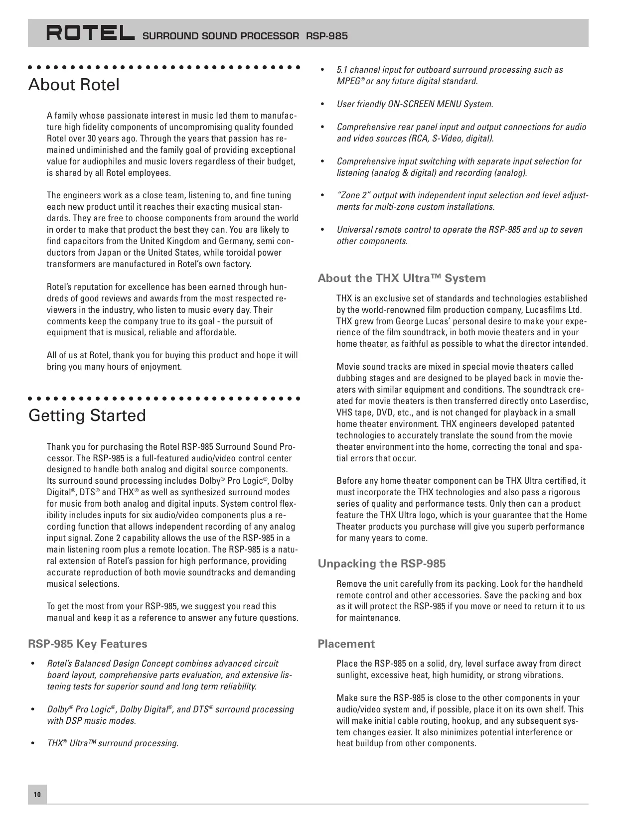
About Rotel
A family whose passionate interest in music led them to manufacture high fidelity components of uncompromising quality founded Rotel over 30 years ago. Through the years that passion has remained undiminished and the family goal of providing exceptional value for audiophiles and music lovers regardless of their budget, is shared by all Rotel employees.
The engineers work as a close team, listening to, and fine tuning each new product until it reaches their exacting musical standards. They are free to choose components from around the world in order to make that product the best they can. You are likely to find capacitors from the United Kingdom and Germany, semi conductors from Japan or the United States, while toroidal power transformers are manufactured in Rotel's own factory.
Rotel's reputation for excellence has been earned through hundreds of good reviews and awards from the most respected reviewers in the industry, who listen to music every day. Their comments keep the company true to its goal - the pursuit of equipment that is musical, reliable and affordable.
All of us at Rotel, thank you for buying this product and hope it will bring you many hours of enjoyment.
Getting Started
Thank you for purchasing the Rotel RSP-985 Surround Sound Processor. The RSP-985 is a full-featured audio/video control center designed to handle both analog and digital source components. Its surround sound processing includes Dolby® Pro Logic®, Dolby Digital®, DTS® and THX® as well as synthesized surround modes for music from both analog and digital inputs. System control flexibility includes inputs for six audio/video components plus a recording function that allows independent recording of any analog input signal. Zone 2 capability allows the use of the RSP-985 in a main listening room plus a remote location. The RSP-985 is a natural extension of Rotel's passion for high performance, providing accurate reproduction of both movie soundtracks and demanding musical selections.
To get the most from your RSP-985, we suggest you read this manual and keep it as a reference to answer any future questions.
RSP-985 Key Features
- Rotel's Balanced Design Concept combines advanced circuit board layout, comprehensive parts evaluation, and extensive listening tests for superior sound and long term reliability.
-
Dolby® Pro Logic®, Dolby Digital®, and DTS® surround processing with DSP music modes.
THX UltraTM surround processing. -
5.1 channel input for outboard surround processing such as MPEG® or any future digital standard.
- User friendly ON-SCREEN MENU System.
- Comprehensive rear panel input and output connections for audio and video sources (RCA, S-Video, digital).
- Comprehensive input switching with separate input selection for listening (analog & digital) and recording (analog).
- "Zone 2" output with independent input selection and level adjustments for multi-zone custom installations.
Universal remote control to operate the RSP-985 and up to seven other components.
About the THX Ultra™ System
THX is an exclusive set of standards and technologies established by the world-renowned film production company, Lucasfilms Ltd.
THX grew from George Lucas' personal desire to make your experience of the film soundtrack, in both movie theaters and in your home theater, as faithful as possible to what the director intended.
Movie sound tracks are mixed in special movie theaters called dubbing stages and are designed to be played back in movie theaters with similar equipment and conditions. The soundtrack created for movie theaters is then transferred directly onto Laserdisc, VHS tape, DVD, etc., and is not changed for playback in a small home theater environment. THX engineers developed patented technologies to accurately translate the sound from the movie theater environment into the home, correcting the tonal and spatial errors that occur.
Before any home theater component can be THX Ultra certified, it must incorporate the THX technologies and also pass a rigorous series of quality and performance tests. Only then can a product feature the THX Ultra logo, which is your guarantee that the Home Theater products you purchase will give you superb performance for many years to come.
Unpacking the RSP-985
Remove the unit carefully from its packing. Look for the handheld remote control and other accessories. Save the packing and box as it will protect the RSP-985 if you move or need to return it to us for maintenance.
Placement
Place the RSP-985 on a solid, dry, level surface away from direct sunlight, excessive heat, high humidity, or strong vibrations.
Make sure the RSP-985 is close to the other components in your audio/video system and, if possible, place it on its own shelf. This will make initial cable routing, hookup, and any subsequent system changes easier. It also minimizes potential interference or heat buildup from other components.
The RSP-985 can generate heat during normal operation. Do not block ventilation openings. Allow a minimum of 10cm (4 inches) of unobstructed open space around the unit. If installed in a cabinet, make sure that there is adequate ventilation.
Make sure there is enough room behind the RSP-985 for easy hookup. Remember, you are connecting many other components to this unit and you'll probably need more space than you think.
Don't stack other objects (components or other items) on top of the RSP-966. Don't let water fall into the RSP-966 as this could damage delicate circuitry.
Front Panel Controls
Although we have designed the RSP-985 to be as simple to use as possible, it is still a complex piece of equipment. For that reason, we suggest you look over the RSP-985's front and rear panels before you start connecting other components to it. The following brief explanations provide an overview of the unit's connections, features, and controls, with number references corresponding to the illustrations at the front of this manual.
Most functions are duplicated on the front panel and on the handheld remote control, a few only on one or the other. These duplications are noted below. In addition, when two reference numbers appear, one refers to the location of the button on the front panel, the other to the location of the button on the handheld remote control.
Standby LED 3
Some of the RSP-985's circuitry (microprocessor, infrared sensor, etc.) remains powered at all times, while the rest of the circuitry is turned on or off by the user. The STANDBY LED lights whenever the RSP-985 is plugged into a live AC outlet but does not necessarily mean that the RSP-985 is totally active. If other front panel LEDs are lit, then the RSP-985 is fully functional.
Note: During system setup, it is possible to select an alternative FULLY-ON power-up mode in which the unit is fully activated whenever it is connected to a live AC outlet.
Standby Switch 2
Similar to a power switch in function, this button switches the RSP-985 from standby mode to fully active mode. If only the STANDBY LED is lit, push the front panel (or handheld remote POWER button) to fully activate the RSP-985. Other front panel LEDs light up and a welcome screen will appear on your TV set. Push the STANDBY switch again to deactivate the RSP-985. You'll see that only the STANDBY LED remains lit.
Note: The STANDBY switch also controls the rear panel AC power outlets. When the RSP-985 is in STANDBY mode, the AC outlets are off. When the RSP-985 is functional, the AC outlets are live.
The operation of the STANDBY switch is somewhat more elaborate when using the RSP-985's ZONE 2 capability. For a detailed explanation, see the ZONE 2 Connections and Operations section of this manual.
Remote Sensor 1
This sensor receives infrared signals from the handheld remote control. Make sure you do not accidentally block this sensor with cables or accessories.
Master Volume Control 4
Turn this control clockwise to raise and counterclockwise to lower the volume to all six main output channels simultaneously.
MASTER VOLUME buttons are also available on the RSP-985's handheld remote control.
Note: The MASTER VOLUME control is mechanically connected to an internal servomotor and responds to commands from the handheld remote. It will rotate in the appropriate direction automatically when adjusting the volume from the remote control.
Use the position of the LED indicator on the knob's outer edge to determine relative volume settings. When the volume control LED blinks, you've engaged MUTE from the remote controller.
Tone Controls 6
BASS and TREBLE controls increase and decrease the audio signal's low and high frequency content. Rotate each one clockwise to increase output in the respective frequency range and counterclockwise to reduce it. The center detent removes each control from the audio path for maximum signal integrity. The ON-SCREEN DISPLAY will show tone control settings as you adjust them.
Note: The BASS and TREBLE controls are bypassed in THX mode and will have no effect, regardless of the setting indicated by the ON-SCREEN DISPLAY.
Listening Input Source Buttons 11
Six front panel pushbuttons select an audio/video input source such as a CD player, VCR, Laser Disc Player, etc. Push any of these buttons (or the duplicates on the handheld remote) to select the desired source. You will hear this source and, if you have selected a video source, see its picture on your TV. An LED indicator on each pushbutton lights to confirm your selection. In addition, the ON-SCREEN DISPLAY confirms your selection.
Note: The source inputs can accommodate either analog signals or digital signals. This selection is made from the ON-SCREEN MENU system during initial setup of the system.
5.1 Channel Input 9
This button overrides all other audio inputs and directly connects an external adaptor to the RSP-985's MASTER VOLUME control and audio outputs. Press this button to listen to the audio input from a 5.1 channel decoder. An LED above the button will light to indicate your selection. All of the RSP-985's circuitry is bypassed, except the MASTER VOLUME control. The 5.1 CHANNEL button is duplicated on the handheld remote control.
Note: The 5.1 Channel Input is an audio-only signal. The video signal from the selected source remains active. The 5.1 Channel input signal is not available for recording or for Zone 2.
Tape Monitor 8
This switch overrides the normal Listening Source Selectors to listen to whatever source component is connected to the Tape Monitor Input jacks. A confirming LED will light whenever the Tape Monitor switch is depressed.
Recording Input Source Buttons 10
The RSP-985 allows you to listen to and/or watch one source while simultaneously recording from a second source. For example, you could listen to a CD while recording from a DVD player to a VCR. The row of RECORDING front panel buttons allows you to select the analog input from any source for recording. Its signal is routed to the rear panel VIDEO 2, 3, and 4 outputs and has no effect on the source selected for listening. LEDs immediately above each pushbutton light to confirm your selection.
The handheld remote does not have RECORDING buttons. However, a recording selection can be made from the remote using the ON-SCREEN MENU system.
Note: The RECORD inputs accept only analog signals. Thus, if you are using a digital connection from a CD player or DVD for listening, you should also connect an analog signal for recording. See the section on Rear Panel Input Connections.
Surround Sound Mode LEDs 5
The RSP-985 provides numerous surround sound modes to accommodate different types of audio and video source material as described below. These LEDs indicate which surround sound mode you've selected. Here is a brief description of the various surround sound modes.
2 CH STEREO provides conventional 2-speaker stereo with no surround sound or other processing. The front left and right speakers are on. The center and surround speakers are off.
MONO combines all channels from the source input into a single signal. The signal is sent to the center channel speaker. If there is no center channel speaker in your system, the signal is sent equally to the front left and right speakers. All other speakers (except the subwoofer) are off. This setting might be suitable for
some TV watching, for example if you have the news report on in the background and do not want the volume levels or effects of the full surround system.
MUSIC 1, MUSIC 2, MUSIC 3, and MUSIC 4 simulate different acoustic environments and are primarily used to recreate ambience when listening to music sources. MUSIC 1 ("Hall") produces the long, bright echo of a large auditorium, suitable for live recordings. MUSIC 2 ("Club") provides the short, dark echo of a crowded club, suitable for pop and rock. MUSIC 3 ("Natural") provides minimal ambience suitable for a wide range of music including jazz, acoustic, and surround encoded music. MUSIC 4 ("Party") sends the full stereo signal with no surround processing to front and rear speakers for maximum output. Experiment to determine which mode best matches your chosen source. All speakers are on in all MUSIC modes.
Note 1: A single LED is used to indicate both the MUSIC 1 and 2 modes while a second LED indicates both MUSIC 3 and 4.
Note 2: The subwoofer is normally not active in MUSIC modes, if LARGE front speakers are selected (although, this setting can be overridden to make the subwoofer active during system configuration).
DOLBY PRO LOGIC® provides proper playback decoding and processing for any Dolby Surround encoded analog audio source, whether it be a music CD, videotape, videodisc, conventional stereo TV broadcast, or satellite broadcast. Dolby Pro Logic processing and playback through a properly calibrated system will preserve the directionality, ambiance, and spatial effects intended by the source's producers.
DOLBY DIGITAL® provides proper playback decoding processing for any discrete Dolby Digital encoded digital audio source such as an AC-3 Laser Disc or DVD disc. Dolby Digital provides up to 5 channels of discrete surround information plus subwoofer.
DTS^® provides proper playback decoding processing for any discrete Digital Theater Systems (DTS) encoded digital audio source such as a Laser Disc or DVD disc. Like Dolby Digital, DTS is a proprietary digital system providing up to 5 channels of discrete surround information plus subwoofer.
THX® Ultra™ is a set of patented technologies developed by THX engineers to accurately translate the sound from the movie theater environment into the home, correcting tonal and spatial errors. When the THX indicator is lit, the following THX technologies are automatically added after the Dolby Pro Logic, Dolby Digital, or DTS decoder.
- Re-Equalization™: The tonal balance of a film soundtrack will be excessively bright and harsh when played back in the home because it was originally designed to be played in large movie theaters using very different equipment. Re-Equalization restores the correct tonal balance for movie soundtracks in the smaller home environment.
- Timbre Matching™: The human ear changes our perception of sound depending on the direction from which the sound is coming. In a movie theater, there is an array of surround speakers so that the surround information is all around you. In
a home theater, you only use two speakers located to the side of your head. The Timbre Matching filters the information going to the surround speakers so that they more closely match the tonal characteristics of the sound coming from the front speakers. This ensures seamless panning between the front and surround speakers.
- Adaptive Decorrelation™: In a movie theater, a large number of surround speakers help create an enveloping surround sound experience. In a home theater, there are only two surround speakers which can reduce spatioussness and envelopment. Surround sound can also collapse into the closest speaker as you move away from the middle seating position. Adaptive Decorrelation slightly changes one surround channel's time and phase relationship with respect to the other surround channel. This expands the listening position and creates the same spacious surround experience as in a movie theater.
By pressing the MOVIE FILTER button on the remote control, you activate the THX technologies described above. Movies that have been encoded in Dolby Digital, DTS, Dolby Pro Logic, Stereo, and Mono can all benefit from activating these THX features. THX should only be activated for movies that were mixed for playback in large movie theaters. It need not be activated for music, made for TV movies, sports, talk shows or other programs mixed for small rooms.
Note: All of the surround modes described above are selected with the MODE button (described below) except Dolby Digital, DTS, and THX. Dolby Digital and DTS are automatically activated when special digital codes in the source material are detected. THX is added to any of the other cinema surround modes using the MOVIE FILTER button on the remote control or during initial system setup from the ON-SCREEN MENUS.
Mode Button
The MODE button selects one of the surround modes described above. To make a selection, press the MODE button (or the SURROUND + button on the remote). The LED above the button will light. Each time you press the button while the LED is lit, the surround mode will cycle to the next available setting as indicated by the SURROUND MODE LEDs. In addition, the surround mode setting may be changed using the ON-SCREEN MENU system.
No selection is required when playing Dolby Digital or DTS source material. These settings are automatically engaged. THX can be added to any of the cinema surround modes by pressing the MOVIE FILTER button on the remote control.
Note: A default MODE selection can be memorized for each input so that whenever you select that input source, the desired mode is automatically engaged. The default setting is made from the ON-SCREEN MENU system during setup of the system described at the end of this manual.
RR-939 Remote Control
The RSP-985 includes a handheld remote control that does far more than operate the RSP-985. The RR-939 is a full-function universal remote control that can operate up to 8 additional audio/video components.
A separate manual, included with the remote, gives detailed information on programming and using the RR-939 to replace all of the remote controls in your system. This section is intended to provide only that information which pertains to the use of the RR-939 to operate the RSP-985.
Note: Many functions duplicate the RSP-985 front panel controls and are listed here only for your reference. Please refer to the previous Front Panel Controls section of this manual if you need additional information.
Programming the RR-939
The RR-939 is preprogrammed from the factory to operate the RSP-985. Should the AUDIO command set on your RR-939 not operate the RSP-985, it's possible that the programming has been inadvertently changed. To program the remote to operate the RSP-985 (AUDIO Button / 3-digit code 002):
Step One: Press the AUDIO button at the top of the remote while simultaneously pressing the MUTE button and hold both for at least one second. The AUDIO button will light in red for 20 seconds, indicating that you have entered the program mode. The next step must be done within this 20 second period, or the RR-939 will revert to its standard operating mode.
Step Two: Use the NUMERIC buttons to enter the 3-digit code (002) for the RSP-985 - press 0, then 0, then 2. The AUDIO button will flash each time you enter a digit.
Step Three: Store the code number by pressing the corresponding AUDIO button again. The button will blink twice to confirm the storage of the code in memory.
To operate the RSP-985, make sure that the AUDIO mode is active by pressing it before you start. If it is active, pressing command keys on the RR-939 will cause the AUDIO button to flash red. Once the AUDIO mode is active, it will stay active unless you press one of the other DEVICE buttons to control a different component.
Power Button 28
Duplicates the function of the STANDBY switch on the front panel. Press to activate the RSP-985. Press again to deactivate.
Volume Buttons

A pair of buttons which duplicate the function of the front panel volume control. Press VOLUME UP to increase the volume and press VOLUME DOWN to decrease the volume. These buttons are also used to change the current settings for a menu choice in the ON-SCREEN MENU system.
Mute Button (remote only) 29
Push this button once to interrupt all AUDIO PREOUT (RCA and DB25) signals – in other words, to turn the sound off. To provide visual indication that the sound is muted, the front panel volume control LED will blink and a MUTE indication will appear in the On Screen Display. Press the MUTE button again to restore previous volume levels.
Input Select Buttons 33
Two rows of buttons which duplicate the function of the six LISTENING INPUT SOURCE buttons on the RSP-985 front panel. Select any input source by pressing the appropriate button.
Note: The TAPE 1 button on the RR-939 duplicates the front panel TAPE MONITOR button. The AUX/V5, PHONO, and TAPE2 buttons are not used in the operation of the RSP-985.
5.1 CH Button 36
Duplicates the 5.1 CH button on the front panel. Selects the 5.1 Channel input, overriding any other source selection.
Surround + Button 30
Duplicates the function of the MODE button on the front panel. Steps sequentially through various surround sound operating modes: 2 CH STEREO, MONO, MUSIC 1, MUSIC 2, MUSIC 3, MUSIC 4, and DOLBY PRO LOGIC. Dolby Digital and DTS are automatically selected when playing appropriately encoded source material.
Your current selection will be indicated by front panel LEDs and by the ON-SCREEN MENU System as you step through the available options.
Movie Filter/THX (remote only) 35
This button activates THX technologies for movie playback. See the prior description of THX for more details.
RE-EQ ON: Re-EQ is one of the THX technologies and can be individually selected. This setting activates Re-EQ without the other THX features.
THX ON: Adds all of the THX features to the cinema modes.
THX OFF: No THX processing.
Note: These settings can also be made during initial system setup from the ON-SCREEN MENUS and memorized so that they are automatically activated for each source input.
Numeric Buttons (remote only) 32
Ten numeric buttons, labeled 1 through 10. Used with the RSP-985 only in entering the 3-digit address code (002) during initial setup.
On-Screen Button (remote only) 34
Push this button to turn on the ON-SCREEN MENU System and its initial SYSTEM STATUS menu. If the ON-SCREEN DISPLAY is already visible, push this button to cancel the Display.
DOWN/UP Buttons (remote only) 31
These two buttons (also labelled RECALL and PRE CH) are used to move up and down in the lists that appear on the ON-SCREEN MENU system.
Enter Button (remote only) 38
This button is used to activate a choice on the ON-SCREEN MENU system. For example, you might select an option to take you to another menu using the DOWN/UP buttons and then press ENTER to execute the command. See below for more information on these menus.
Back Button (remote only) 37
The BACK button is used to cancel a selection on an ON-SCREEN MENU and return to the previous menu.
Rear Panel Input Connections
This section of the manual provides information on the audio and video signal input connections on the rear panel of the RSP-985.
Note: DO NOT plug any system component into an AC source until system hookup is complete and you are confident that all component-to-component connections have been properly made.
All video cables should have a 75 ohm impedance rating. Although conventional audio interconnects will pass a video signal, their construction and limited bandwidth impose a performance penalty because, in part, they do not adhere to the 75 ohm standard. The S/PDIF digital audio interface standard specifies a 75 ohm transmission line and all good digital cables adhere to this requirement. Because the video and S/PDIF standards are so close, you can use a video cable for digital audio data transmission. We strongly advise that you NOT substitute a conventional analog audio interconnect cable for either digital or video.
RCA Audio and Video Inputs 12
Six sets of RCA inputs (CD, TUNER, VIDEO 1, VIDEO 2,VIDEO 3, andVIDEO 4) accept line level audio and composite video signals from source components. All six sets of inputs accept left and right channel audio plus a video signal.
All RCA-type connections on the RSP-985 follow these standard color codes:
Left channel audio = RCA jack with white inset
Right channel audio = RCA jack with red inset
Composite video = RCA jack with yellow inset
Connect the OUTPUTS of your source components to the appropriate INPUTS on the RSP-985. For example, if your system includes a CD player, connect its left and right channel analog outputs to the RSP-985's CD inputs. To hookup a video source, connect its analog audio outputs to one pair of the RSP-985's VIDEO audio inputs and its video composite RCA output to the corresponding composite RCA video input.
S-Video Source Inputs 23
[See Figure 5]
These mini-DIN inputs allow the RSP-985 to receive S-Video signals from appropriately-equipped source components as an alternative to the standard RCA video inputs described above.
If you opt for S-Video connections, remember that long S-Video cable runs can cause significant signal degradation. In some difficult system configurations, composite connections may actually be preferable. In all cases, keep your cables as short as possible to insure the best performance.
Note: You may not get the best signal from a Laser Disc player by using the S-Video output. Because the format is older, LD players add a circuit to separate the luminance (black and white) from the chrominance (color) information that make up the complete video signal. This extra circuitry may actually degrade the apparent resolution of an LD player's S-Video output. Experiment to determine which output provides a sharper picture in your system.
S-Video hookup is straightforward. Simply connect the S-Video output of each video source component to the appropriate S-Video input on the back panel of the RSP-985 in place of the RCA composite video connections. Remember that you will still need to use the RCA-type connections for the audio signals from each source component.
When connecting video source components, make sure that all audio and video signals from one component connect to the same set of inputs on the RSP-985. For example, if you connect your VCR to the VIDEO 2 inputs, make sure that both the audio and video signals are connected to the VIDEO 2 inputs.
Digital Audio Inputs 19
The RSP-985 features a complete decoding and D/A conversion capability which accepts digital input signals from source components. These include digital signals from CD players (44.1kHz sampling rate), satellite TV tuners (32kHz sampling rate), and 5.1 channel Dolby Digital and DTS signals from DVD and Laser Disc players (32kHz to 48kHz sampling rate). The digital circuitry senses the incoming signal type and adjusts to it automatically.
To take full advantage of various digital sources, the RSP-985 accepts digital signals from source components in two different formats. The digital inputs are as follows:
OPTICAL: Allows connection of a standard optical digital output from a digital TV tuner, DVD player, or other source component. Requires an optical digital cable. Optical digital inputs are available on the back panel for the TUNER input and the VIDEO 4 input.
COAXIAL: Standard digital connectors for use with the digital output of any component. Coax digital connectors are available for the CD, VIDEO 1,VIDEO 2, andVIDEO 3 inputs.
Note: To connect a Laser Disc player's AC-3 RF output connection, you must use an external RF demodulator to convert the RF-modulated AC-3 signal to a conventional digital signal which is then connected to the RSP-985's coax digital input.
To use the digital inputs, connect the appropriate cable from the digital output of your source component to the corresponding digital input on the RSP-985.
It is necessary to configure each source to use the desired input (digital or analog). This configuration is done using the ON-SCREEN MENU system and is memorized so that simply selecting a SOURCE INPUT button activates the appropriate audio input.
Note: The RSP-985 is a digital component. Incoming analog signals are converted to the digital domain for processing. To avoid a D/A conversion at the source component and subsequent A/D conversion at the RSP-985 input stage, it is best to use digital signal connections whenever possible. However, you should still hook up analog audio signal connections from each source because only analog inputs are available at the tape monitor outputs, for recording and for use in Zone 2.
5.1 Channel Audio Input 16
This 25-pin input connects six discrete channels of analog information from an outboard processor.
Many external adaptors provide a choice of RCA or DB25 outputs. We suggest that you use a DB25-to-DB25 cable to reduce the number of cables and to insure proper channel-to-channel continuity. If your external adaptor does not have a DB25 output, you will need to purchase a multi-RCA to DB25 adaptor cable from your authorized Rotel dealer. Be sure to observe proper channel continuity.
Note: The 5.1 Channel Input is an audio-only signal. The video signal from the selected source remains active. The 5.1 Channel input signal is not available for recording or for Zone 2.
RCA Tape Monitor Inputs 14
A pair of standard RCA inputs accept the left and right analog audio signals from a cassette deck or other audio tape recorder. These inputs are activated when the front panel TAPE MONITOR button is pressed.
External In Jack

This 3.5 mm jack accepts a remote infrared sensor which duplicates the function of the front panel IR sensor in installations where the front panel sensor could be blocked by a cabinet. See your authorized Rotel dealer for a selection of remote sensors that will work with your RSP-985.
Rear Panel Output Connections
This section of the manual provides complete information on all of the audio and video signal output connections on the rear panel of the RSP-985. For convenience, each topic begins with an overview of the particular connection, followed by detailed hookup instructions.
RCA Audio and Video Outputs 13
[See Figure 4]
These three sets of RCA outputs (VIDEO 2,VIDEO 3,andVIDEO 4) include left and right channel audio plus composite video outputs from the RSP-985 to appropriate components (VCR, etc.) for recording or further processing. Standard color coding applies.
Connect the RSP-985's VIDEO 2 left and right audio outputs to the audio inputs of the first source component. Then, connect the VIDEO 2 composite video output to the video input of the same source component. Repeat these steps for VIDEO 3 and VIDEO 4 connections.
To avoid mistakes, make sure that you:
- Connect the source component's outputs to the appropriate RSP-985 inputs
- Connect the appropriate RSP-985 outputs to the source component inputs.
- Make sure that whatever video component is connected to the Video 2 inputs is the same component connected to the Video 2 outputs, etc.
Note 1: The signal available at these outputs is determined by the RECORDING input selection buttons and is not necessarily the same source as that selected by the LISTENING input selection buttons.
Note 2: A source's signal cannot be sent back to itself. For example, if you selectVIDEO 2 with the RECORDING select buttons, the outputs forVIDEO 2 will be muted and you can only record from theVIDEO 3 orVIDEO 4 outputs.
Note 3: Only analog input signals are routed to the VIDEO OUT jacks. If you are using a digital input, you should also connect the analog output of the source component for recording.
S-Video Outputs 24
[See Figure 5]
Mini-DIN outputs give you the option of using S-Video outputs instead of the RCA composite video connections described above.
Note: Composite video signals cannot be converted to S-Video signals. There will be no signal available at the S-Video outputs unless S-Video connections have also been used at the inputs.
If you have opted for S-Video connections rather than composite RCA video connections, connect the S-Video outputs for VIDE0 2 to the S-Video input on your first source component.
Remember that you are merely substituting an S-Video connection for the standard RCA-style composite video connection. Your audio connections will still use the RCA outputs described above. Also remember to observe the same component-to-component continuity between audio and video signals described above.
Repeat the same process using VIDEO 3 and VIDEO 4 if you have additional video source components.
Main Processor RCA Audio Outputs 18
[See Figure 3]
The RSP-985 sends six channels of audio to the power amplifiers. These outputs (6 individual RCA-style jacks) direct the RSP-985's main output to power amplifiers for speakers in the primary listening/viewing area. These six outputs (Left Front, Center Front, Right Front, Left Surround, Right Surround, and Subwoofer) connect the RSP-985's main audio output to a multichannel power amplifier or multiple power amplifiers for the primary listening area.
Standard color coding applies with black insets to distinguish Center Channel and Subwoofer outputs from Left (white) and Right (red) Front and Rear outputs. To hook up the RCA main audio outputs, connect a standard audio cable from each output to the input of the amplifier channel that will power the corresponding speaker. In a full home theater system, you will need to make six different connections corresponding to the six speakers (Left Front, Center Front, Right Front, Left Surround, Right Surround, and Subwoofer).
It is important to make sure that you have the correct output connected to the proper amplifier channel. Take your time and you will have no trouble getting it right.
Main Processor 25-pin Audio Outputs 17
[See Figure 3]
As an alternative to the RCA outputs, the RSP-985 also provides DB25 multi-pin output connector which carries all output channels in a single cable. The DB25 output connector provides exactly the same signal as the RCA outputs, but is more convenient for use with Rotel, or other, multichannel amplifiers equipped with a matching DB25 input. Choose whichever is most convenient for your system hookup.
To use the DB25 output connections, simply connect a female-to-male DB25 audio cable from the output of the RSP-985 to the matching input on the multichannel power amplifier.
TV/Monitor Video Outputs 22
[See Figure 3]
The video output of the RSP-985 is sent to your TV monitor from either an RCA-type composite video connection or an S-Video connection. Use the type of connection appropriate for your monitor and system.
For example, if you've chosen to use S-Video connections, run an S-Video cable (with mini-DIN connectors) from the RSP-985's S-Video output to your monitor's S-Video input.
If you have chosen a composite interface, connect the RSP-985's RCA output jack to the matching RCA input on your television monitor.
Note: The RSP-985 cannot convert composite RCA video signals from source components to an S-Video signal to send to the TV monitor. Unless all of your video sources have S-Video connections, you may decide to use RCA composite signals for ALL video connections. Alternatively, if your TV monitor has two selectable inputs, you could connect the RCA output of the RSP-985 to one input and the S-Video output to the other. This would require switching between the two inputs on the TV monitor in order to watch an RCA composite or an S-Video components. This is the only way to have a "mixed" system with some RCA composite and some S-Video sources.
Tape Monitor Audio Outputs 14
[See Figure 4]
A pair of RCA-type audio outputs send a signal to an audio recording device (cassette deck, DAT, or Mini-Disc recorder, etc.). The analog signal from any of your source components will be routed to these outputs for recording, depending on the selection made with the LISTENING input buttons.
Connect audio cables from the RSP-985's TAPE MONITOR OUT jacks to your recorder's analog inputs.
Note: Only analog input signals are routed to the TAPE MONITOR OUT jacks. If you are using a digital input, you should also connect the analog output of the source component for recording.
Rear Panel AC Power Connections
AC power 21
Your RSP-985 is configured at the factory for the proper AC line voltage in the country where you purchased it (115 volts/60Hz AC in the USA and 230 volts/50Hz AC in Europe). The AC line configuration is noted on the back of your unit.
Plug the supplied power cable into the AC receptacle on the back of the unit. Then, plug into an appropriate AC outlet.
AC Convenience Outlets
Two outlets let you plug AC cords from source components into the back of the RSP-985 so that they will be turned on and off automatically. The outlets are powered whenever the RSP-985 is fully active. It is off when the RSP-985 is in STANDBY mode.
Note: We DO NOT RECOMMEND using this outlet for a power amplifier. Do not exceed the maximum 500 watt capability of these switched outlets.
Zone 2 Connection and Operation
The RSP-985 provides a second zone capability for a separate amplifier and pair of speakers in a remote location in your house. From the remote zone, you can select a source component (even if different from the source playing in the main listening room), adjust the volume level in the remote zone, and (depending on the remote control you are using) operate the source components.
To take advantage of the Zone 2 capability, you will need additional components: a pair of speakers installed in the remote zone and a power amplifier to drive them.
Although Zone 2 can be controlled from the RSP-985's ON-SCREEN MENU system, operation from the second zone requires the installation of an infrared repeater system such as a Xantech, Niles, etc. This repeater system relays infrared remote control commands from a handheld remote to the REMOTE EXTENSION IN repeater input on the back of the RSP-985. Ask your authorized Rotel dealer for additional information on repeater systems and their installation.
Several points to keep in mind about the Zone 2 function:
- An infrared repeater system (Xantech, Niles, et al) should be used for Zone 2 control via the 3.5mm REMOTE EXTENSION IN jack on the back panel
- Zone 2 is immediately active when the RSP-985 is turned on, either at a zero volume level or at the last previous volume depending on the "Zone 2 Auto-Mute" setting chosen from the ON-SCREEN MENU system during initial system setup. By default, Auto-Mute is engaged, meaning that every time you turn the unit off, the volume in the remote zone is muted and must be manually raised the next time Zone 2 is used. If Auto-Mute is not engaged, the remote zone will begin playing at the previous volume the next time the RSP-985 is activated.
-
The RR-939 remote control supplied with the RSP-985 will operate Zone 2 if used in conjunction with a repeater system from the remote zone. It can also be programmed to operate Rotel source components via the RSP-985's REMOTE EXTENSION OUT jack.
-
All source components connected to the RSP-985's analog audio inputs (except the TAPE MONITOR and 5.1 CHANNEL input) are available at the line level output for Zone 2. The ZONE 2 outputs are independent of the main outputs. You can select a different source or adjust Zone 2 volume without effecting the MAIN outputs in any way.
- Avoid sending the same infrared command to the RSP-985 front panel sensor and the Zone 2 repeater at the same time. This means that Zone 2 must be in a different room from the RSP-985.
Zone 2 Power On/Off Operation
With the factory default settings, the RSP-985 provides totally independent power on/power off operation for both zones. Pressing the STANDBY button on the front panel or from the remote in the main room activates or deactivates the RSP-985 in the main room only and has no effect on Zone 2. Conversely, using the remote control from Zone 2 activates or deactivates Zone 2 only and has no effect on the main listening room. In other words, Zone 2 can be turned on without turning on the main room and vice versa. Each room can only be turned on or off from that room.
Note: In this default mode, you cannot deactivate the entire system from the front panel of the RSP-985. To turn off ZONE 2, you would have to go to ZONE 2 and use the remote control STANDBY button to deactivate ZONE 2 from that location. You can change this default operation by selecting the AUTO-MUTE NO selection at the SYSTEM SETUP MENU. When AUTO MUTE is disabled, the entire system (both zones) is activated or deactivated when the front panel STANDBY button is pressed. See the section on the SYSTEM SETUP MENU for details of changing this setting, either on a permanent basis or as a temporary measure to allow you to deactivate ZONE 2 from the front panel.
Zone 2 Audio Outputs 15
[See Figure 6]
These variable line-level RCA-type audio outputs send the Zone 2 audio signal to a stereo power amplifier driving a pair of speakers in the remote zone.
Although you have the option of using an integrated amplifier or a receiver to power the remote speakers, we strongly suggest using a fixed-gain power amplifier. This simplifies system installation and operation. Your authorized Rotel dealer may make another recommendation based on specific system requirements.
If you are configuring your system for Zone 2 operation, connect the left and right Zone 2 outputs on the RSP-985 to the left and right channels of the amplifier powering the remote speakers, using conventional RCA audio cables.
Remote External Sensor/Repeater Jacks

[See Figure 6]
These 3.5 mm mini-jacks allow your RSP-985 to send/receive command codes from industry-standard infrared transmitters and receivers via hard-wired connections. They are used in configuring your RSP-985 with the proper IR connections for Zone 2 operation.
These 3.5mm mini-jack connections provide easy incorporation of third party infrared transmitters and repeaters (Xantech, etc.) for total control of custom installed and multi-zone systems.
The REMOTE EXTENSION IN jack accepts signals from infrared repeaters located in a remote area of your home. This receptacle is required for connecting a remote sensor/transmitter to enable operation of the RSP-985's ZONE 2 functions.
The REMOTE EXTENSION OUT jack sends signals from the REMOTE EXTENSION IN jack to a remote infrared repeater or to Rotel CD players, cassette decks, or tuners with a compatible rear panel remote connector.
The EXTERNAL IN JACK located above these two jacks is for use with an external IR sensor duplicating the front panel IR sensor and should not be used for ZONE 2 IR connections.
Note: ZONE 2 and its IR repeater should be in a different area from the main room. The RSP-985 should not be within range of Zone 2's remote control to prevent IR commands intended to control Zone 2 from inadvertently controlling the main room operations.
On-Screen Display and System Configuration
The RSP-985 features two on-screen systems to help operate the system. The first is a simple ONE-LINE DISPLAY that appears at the bottom of the TV screen whenever primary settings (Volume, Input, etc.) are changed. ONE-LINE DISPLAY can be turned off during the configuration of the system if you prefer.
A more comprehensive ON-SCREEN MENU system is available at any time by pressing the ON-SCREEN button on the remote control. This system includes intuitive menus that guide you through the setup and operation of virtually every function and setting of your RSP-985 using the buttons on the remote control.
Navigation Buttons 27 31 34 37 38
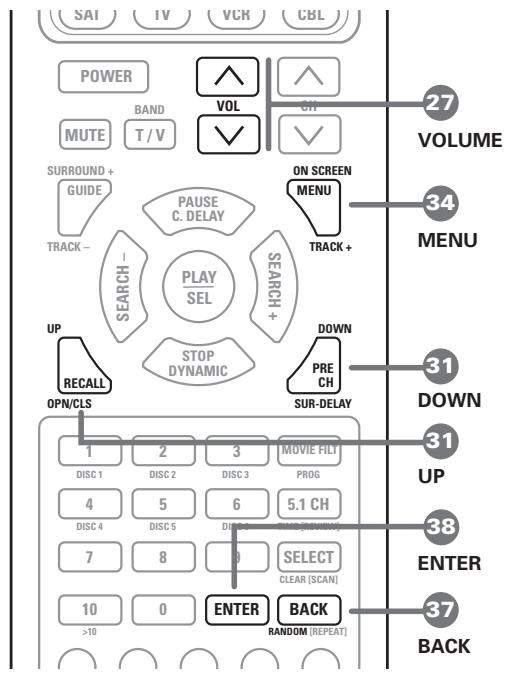
The following buttons are used to navigate the ON-SCREEN MENU system:
ON-SCREEN/MENU Button: 34 To display the main SYSTEM STATUS screen. All other menus are reached from this menu. If a menu is already visible, push this button to cancel the display.
DOWN/UP Buttons: 31 To move up and down in the lists that appear on the ON-SCREEN MENU system.
VOLUME DOWN/UP Buttons: 27 To change the current settings for a selected menu choice in the ON-SCREEN MENU system.
ENTER Button: 38 To execute a command on the ON-SCREEN MENU system, generally to move to the next menu or confirm a choice.
BACK Button: The BACK button is used to cancel a selection on an ON-SCREEN MENU and return to the previous menu.
Note: There is no need to memorize these buttons. A help system at the bottom of each ON-SCREEN MENU reminds you which buttons to press.
Figure 7 at the front of this manual shows the menus that constitute the ON-SCREEN MENU system and how to reach them. Most of the menus are used to configure the system and will not typically be used during normal operation. Details of each menu follow:
Start-up Screen
The RSP-985's ON-SCREEN MENU system automatically appears on your TV monitor whenever you take the RSP-985 out of STANDBY mode. The first screen you'll see is the START-UP screen.
System Status Screen
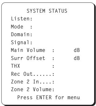
The SYSTEM STATUS screen provides the status all of the important settings of the RSP-985 and a starting point for reaching all other screens and menus. This screen is available at any time by pressing the ON-SCREEN button on the remote control. The screen displays the following status information:
LISTEN: the current source selected
MODE: the current surround mode
DOMAIN: whether a DIGITAL or ANALOG signal is active for the listening source
SIGNAL: type of digital signal available at the selected input, for example: DOLBY DIGITAL, DIGITAL AUDIO, DTS, NO SIGNAL, or ANALOG
MAIN VOLUME: the output volume setting
SURR OFFSET: a temporary increase or decrease in the surround speaker volume for more or less emphasis on surround effects. The setting is made with the SEARCH +/- buttons on the RR-939 remote and reverts to the calibrated settings when the surround mode is changed or the unit is powered off.
THX: current status of the additional cinema circuitry - THX ON, THX OFF, or RE-EQ ON.
REC OUT: which source is selected for the recording outputs
ZONE 2 IN: which source is selected for Zone 2
ZONE 2 VOLUME: the volume setting for Zone 2
The SYSTEM STATUS screen simply provides information. None of the settings can be adjusted from this screen. To make changes to the settings, go to the MAIN MENU by pressing the ENTER button on the remote control, as indicated at the bottom of the SYSTEM STATUS screen.
Main Menu Screen
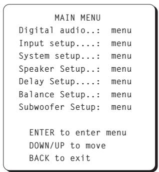
The MAIN MENU screen is the entry point for all of the RSP-985's settings and setup menus where system configuration settings can be made. These are typically accessed only during initial system configuration and are not used in day-to-day operation:
DIGITAL AUDIO MENU: Reach this menu by moving the highlight to this line and pressing the ENTER button. This takes you to a menu for setting up digital sources.
INPUT SETUP: Reach this menu by moving the highlight to this line and pressing the ENTER button. This will take you to a menu for configuring each input including selection of digital or analog connections, type of digital connection, input levels, etc.
SYSTEM SETUP: Reach this menu by moving the highlight to this line and pressing the ENTER button. This takes you to a menu for basic system settings, Zone 2 settings, etc.
SPEAKER SETUP: Reach this menu by moving the highlight to this line and pressing the ENTER button. This will take you to a menu for configuring the number and type of speakers in the system.
DELAY SETUP: Reach this menu by moving the highlight to this line and pressing the ENTER button. This takes you to a menu for configuring delay times to each speaker in surround modes.
BALANCE SETUP: Reach this menu by moving the highlight to this line and pressing the ENTER button. This will take you to a menu for configuring the relative volume levels of each speaker.
SUBWOOFER SETUP: Reach this menu by moving the highlight to this line and pressing the ENTER button. This takes you to a menu for configuring your subwoofer for various surround modes.
Dolby Digital Setup Menu
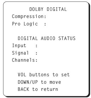
This menu, which is reached from the MAIN MENU, provides status information and setup options for digital inputs.
The first two lines of the screen allow you to set system-wide configuration options for Dolby processing:
COMPRESSION: Today's digital sources are capable of extremely high dynamic range (the difference between the softest and loudest sounds). In some cases, the available dynamic range may tax the amplifiers or speakers. In other cases, it may be desirable to compress the dynamic range when listening at low volume levels. This configuration option allows you to select three different levels of dynamic range: OFF (no compression), MODERATE, or LATE NIGHT (maximum compression). The factory default is OFF (no compression). If loud passages are causing distortion or audible stress to the system, try a setting with more compression.
PRO LOGIC: This setting determines how the RSP-985 processes 2-channel Dolby Digital or DTS source material. Processing of discrete multi-channel surround material is automatic. But, some source material, such as a CD played on a Dolby Digital DVD or an older movie soundtrack, might have either a 2-channel stereo signal or a matrix encoded two-channel Pro Logic signal. In some cases, the RSP-985 can detect an encoded ID tag which tells it how to process a 2-channel signal. In other cases, it cannot.
The options for processing 2-channel signals from a Dolby Digital or DTS source are as follows.
Auto/On: Turns on Dolby Pro Logic decoding for all signals unless the RSP-985 is able to sense a control code identifying the 2-channel material as conventional stereo, in which case Pro Logic is turned off automatically. This is the default setting, suitable for most applications.
Auto/Off: Turns off Dolby Pro Logic decoding and plays 2-channel stereo, unless a Pro Logic signal is specifically identified, in which case Pro Logic will be activated.
On: Turns on Dolby Pro Logic decoding for all 2-channel signals, disabling the automatic sensing.
Off: Turns off Dolby Pro Logic decoding for all 2-channel signals, disabling the automatic sensing. Plays conventional 2-channel stereo.
Note: The above settings only effect 2-channel signals from a Dolby Digital or DTS source. Discrete digital surround signals (e.g. 5.1 channel signals) will play correctly regardless of the setting.
The three lines in the DIGITAL AUDIO STATUS portion of the menu screen provide information about the current status of Dolby Digital inputs:
INPUT: Shows the name of the input source.
SIGNAL: Shows the format of the current source, i.e. DOLBY DIGITAL, DTS, etc.
CHANNELS: Dolby Digital and DTS signals can contain up to six discrete channels of information - left, center, right, left rear, right rear, and a subwoofer or low frequency effects channel. This status line indicates how many channels are active in the current source material.
Input Setup Menu
INPUT SETUP
Input:
Input Domain.:
Volume Offset: dB
Analog Level.: 2V
THX.
Default.....
VOL buttons to set
DOWN/UP to move
BACK to return
The RSP-985 accepts both analog and digital signals. The INPUT SETUP menu allows you to configure each input:
INPUT: Select the input you wish to setup by highlighting this line and stepping through the available choices with the VOLUME DOWN/UP buttons. You will need to configure each input, repeating the following configuration sequence several times, each time selecting a different input.
INPUT DOMAIN: Select ANALOG or DIGITAL or AUTO depending on the type of signal connection you have made by stepping through the available choices with the VOLUME DOWN/UP buttons. Using a DIGITAL signal, if available, avoids a D/A conversion in the source component and A/D conversion in the RSP-985. Note that even when using a digital input, you still should make analog connections from the source. These will be used for recording, regardless of the setting on this menu. Selecting AUTO for the input will check for the presence of a DIGITAL signal and automatically revert to an ANALOG input if no DIGITAL signal is present.
VOLUME OFFSET: This menu item adjusts the volume of each source component so that the volume level remains relatively constant when switching between sources and so that the signal does not overload the RSP-985. Typically, you determine which source has the lowest level and then match the others to that one. Adjust the level using the VOLUME DOWN/UP buttons. Note that you are matching the perceived level you hear from that source, not the dB readout that appears on-screen.
Note: It is essential not to set the source input levels so high that the signal overloads the RSP-985's input circuitry. Adjust to match the quietest source, not the loudest.
ANALOG LEVEL: The maximum input level for analog sources is 2V RMS. It is possible that a source with a very high output level, such as some CD players, may overdrive the input. This will be indicated with the word CLIP appearing on the screen. Should this occur, change the ANALOG LEVEL menu setting for that source to 4V which will reduce its input level by 6dB.
THX: This setting determines which additional surround circuitry should be activated for the current input. Choices are THX ON, RE-EQ (activated Re-EQ only), and THX OFF.
DEFAULT: This setting specifies the default surround mode for each input. Choices are 2 CH STEREO, MONO, MUSIC 1-4, and PRO-LOGIC. DOLBY DIGITAL are DTS are automatically selected when an appropriate signal is present.
Once you have completed the settings for all of your input sources, return to the MAIN MENU by pressing the BACK button.
System Setup Menu
SYSTEM SETUP
Recording:
Zone 2 in....
Zone 2 volume...
Power-on mode...
One-line display:
Zone 2 auto mute:
Factory Defaults: menu
VOL buttons to set
DOWN/UP to move
BACK to return
This menu, which is reached from the MAIN MENU, provides access to a wide range of system-wide configuration options.
RECORDING: Select a source for the VIDEO 2, 3, and 4 record outputs by moving the highlight to this line and then stepping through the six available input choices using the VOLUME DOWN/UP buttons.
ZONE 2 IN: Select a source for Zone 2 by moving the highlight to this line and then stepping through the six available input choices using the VOLUME DOWN/UP buttons.
ZONE 2 VOLUME: Set the volume level for Zone 2 by moving the highlight to this line and then adjust the volume up or down using the VOLUME DOWN/UP buttons.
POWER-ON MODE: This setting determines how the RSP-985 powers up when connected to an AC outlet. In the default STANDBY mode, the unit goes into a standby status when AC is applied and must be fully activated from the front-panel or remote control. In the DIRECT mode, the unit is fully active whenever it is connected to AC. This may be desirable in installations where the RSP-985 is plugged into a switched outlet.
ONE-LINE DISPLAY: This option determines whether a one-line information display appears on the TV screen for 5 seconds every time an RSP-985 setting is changed. Some users prefer to turn it off so that it never appears. Change the setting by highlighting this menu line and using the VOLUME DOWN/UP buttons to change from ON to OFF or vice versa.
ZONE 2 AUTO-MUTE
Determines whether Zone 2 is automatically muted when the RSP-985 is activated. If auto-mute is YES, the volume of Zone 2 will be muted when the system is turned on. If auto-mute is NO, the volume in Zone 2 will return to its last previous setting when the system is turned on.
FACTORY DEFAULTS: Highlight this option and press the ENTER button on the remote control to go to the FACTORY DEFAULT menu which allows you to return ALL system settings to the factory default settings.
Press the BACK button to return to the MAIN menu.
Speaker Setup Menu
SPEAKER SETUP
Main
Center:
Surrounds.....
Subwoofer.....
VOL buttons to set
DOWN/UP to move
BACK to return
This menu, which is reached from the MAIN menu, allows you to configure the RSP-985 to make optimum use of the capabilities of the speakers in your system. Using these settings, the RSP-985 adjusts its crossovers and digital processing to direct signals to the appropriate speakers.
Home theater speaker systems vary considerably in their size and performance, particularly in their bass output. For this reason, today's surround sound processors feature elaborate logic which can send bass information from movie soundtracks to the speaker(s) best able to handle it - subwoofer and/or LARGE speakers. For optimum performance, it is necessary to tell the RSP-985 the number and type of speakers in your system.
The following configuration instructions refer to LARGE and SMALL speakers. The size refers more to the bass performance of the speaker than its physical size. A full-range speaker that has extended bass response is considered LARGE. A compact minispeaker with limited bass response or power handling is considered SMALL.
While understanding the terms LARGE and SMALL is useful, it is probably more important to understand what these different speaker types mean in terms of system performance. This will help determine how you should configure your system. As a general rule, the system will redirect bass information away from SMALL speakers and send it to the LARGE speakers and/or the SUBWOOFER in your system.
Things become a little more complex in systems with a subwoofer. For example, the system will generally not redirect bass information away from a LARGE speaker to the subwoofer. Thus, the decision you often need to make when faced with a choice of LARGE or SMALL is whether you want the particular speaker to play the deep bass or whether you would prefer that the deep bass be sent to the subwoofer. If you have invested in a subwoofer for your system, you might decide to send all of the bass to it, regardless of how capable the other speakers in the system may be. In this case, you would tell the RSP-985 that all of your speakers are SMALL, without regard to how big they may actually be.
An alternative configuration for setting up front SMALL speakers with a subwoofer would be to follow the speaker manufacturer's instructions, wiring the SMALL speakers to the subwoofer's
crossover and then connecting the subwoofer directly to the front speaker connection terminals. In this arrangement, the speakers would be classified as LARGE and the subwoofer setting would be OFF for all surround modes. No information will be lost during playback because the system knows to redirect the bass information to the front LARGE speakers. This configuration may be optimal for many users as it can improve the way the bass integrates into the listening room and ensure correct satellite speaker operation by using the speaker manufacturer's own crossovers.
To configure your system, highlight each of the following menu lines and use the VOLUME DOWN/UP buttons to make the setting that best matches your speakers.
MAIN (Small/Large): This menu setting tells the RSP-985 what kind of main front left and right speakers you are using. Use the LARGE setting if your main left and right speakers are full range designs with good bass response capability. If you are using satellite mini-speakers or if you have THX certified front speakers, choose the SMALL setting to redirect LFE bass frequencies to the subwoofer. Highlight this menu line and use the VOLUME DOWN/UP buttons to make the appropriate setting. If you have THX certified front speakers, choose the SMALL setting.
CENTER (small/large/none): Surround sound derives much of its spatial accuracy from a center channel speaker located very close to a TV. This center channel speaker anchors dialog information to your screen for greater coherence between the apparent point of origin for picture and sound.
Use the LARGE position if your system's center channel speaker is capable of full-range, extended bass response. In this position, bass frequencies are handled by the center channel speaker itself.
Use the SMALL position if your center channel speaker has more limited low frequency capability or if you have a THX certified center channel speaker. Low frequencies below 80 Hz are redirected to the front left and front right speakers (or to a subwoofer) so they will not overload the center channel speaker. When no subwoofer is used, all bass frequencies below 80 Hz are sent to the front left and right speakers. When a subwoofer is used, bass below 80 Hz is automatically sent to the subwoofer.
Select the NONE setting if your system does not have a center channel speaker. The RSP-985 turns the center channel output off and divides the center channel signal equally between left and right front speakers.
SURROUNDSD (small/large/none): Surround speaker performance varies widely from system to system. It is important to tell the RSP-985 what type of surround speakers you have in your system.
If your rear surround speakers are capable of sustained low frequency output below 80Hz , select the LARGE setting. This ensures that your rear speakers receive a full bandwidth signal whenever available from the RSP-985.
If your rear speakers have limited bass capability or if you have THX certified surround speakers, use the SMALL setting. This limits the RSP-985's low frequency output so that the speaker is not overdriven. The result will be cleaner reproduction of ambience and effects information. In the SMALL position, the bass information originally intended for particular speakers is sent to the Subwoofer or LARGE speakers instead. Fundamental tones are not lost but simply redirected to the speakers best able to handle them.
If your system has no rear surround speakers, select the NONE setting. Surround information is sent to the front speakers and, in certain cases, the subwoofer.
SUBWOOFER (On/Off): Use the ON setting if your system has a subwoofer. This activates the built-in electronic crossover to route low frequencies (called "redirected bass") from any SMALL speakers to the subwoofer, which is best capable of reproducing these low frequency signals. If your system does not have a subwoofer, put this switch in the OFF position. This sends the redirected bass signals plus the LFE channel (Low Frequency Extension, the .1 channel) to LARGE speakers in the system.
Note: In STEREO, DOLBY PRO LOGIC, and DSP MUSIC modes, bass is directed to the front speakers and NOT to the subwoofer when LARGE is selected. For subwoofer output in these modes with LARGE front speakers, override the bass management system with a setting in the SUBWOOFER SETUP menu.
Once you have completed the settings for all of your speakers, return to the MAIN menu by pressing the BACK button.
Delay Setup Menu
DELAY SETUP
<1ms:1ft>
Left.. ms
Center..... ms
Right.. ms
Right surround: ms
Left surround.: ms
Subwoofer..... ms
VOL buttons to set
DOWN/UP to move
BACK to return
This menu, which is reached from the MAIN menu, allows you to set the delay time for each individual speaker. This is an important feature as it enables the sound from each speaker to arrive at the listening position at the same time, even when they are not all placed at equal distances from the listener. This preserves accurate sound imaging even with irregular speaker placements.
As a rule of thumb, increase the relative delay to speakers located closer to the seating area and decrease the relative delay to speakers located farther from the seating area. Start by measuring the distance from your seating position to each speaker. The speaker farthest away should receive no additional delay. Each of the other speakers will receive one millisecond of delay for each foot (30 cm) closer to you than the farthest speaker. For example, if the left front speaker is farthest away at 13 feet and the left rear speaker is 7 feet away, you should add 6 milliseconds of delay to the left rear speaker. Continue setting delays for each speaker until you have compensated for each speaker that is closer to you than the farthest speaker.
Once you have completed the delay settings for all of your speakers, return to the MAIN menu by pressing the BACK button.
Balance Setup Menu
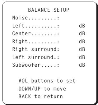
This menu, also reached from the MAIN screen, adjusts the relative volume level of all six speakers. Just as you set the delays in the previous step to ensure that the sound from all of the speakers arrives at the same time, you also need to ensure that the volume of the sound from all speakers is the same.
To calibrate levels, turn on the built-in noise generator by highlighting the NOISE line of the BALANCE SETUP menu and use the VOL DOWN/UP buttons to choose the AUTO position. You will hear noise coming from the first speaker. After three seconds with no adjustment, the test signal will automatically shift to the next speaker, continuing through all of the speakers in sequence.
While seated in the normal listening location, listen to hear if one speaker is significantly louder or quieter than the others. It is best to identify a speaker that is in the middle range (neither the loudest nor the quietest) to use as a reference.
Leaving the volume level of the reference speaker unchanged, cycle through the other speakers, this time adjusting each of their volume levels up or down to match the reference speaker, using the VOLUME DOWN/UP buttons to change the volume of the highlighted speaker while the test noise is coming from it. Alternatively, you can switch to the MANUAL noise setting which will send the noise signal to the speaker you highlight on the menu.
Continue through all of the speakers until they produce the same output level. It may be necessary to cycle through the speakers, adjusting volumes several times to get the desired result.
It is also possible to adjust the balance with an external signal, such as a test signal disc. In this case, turn the noise setting to OFF and proceed directly to volume settings of individual speakers.
Note: This calibration will be more accurate using a sound pressure level (SPL) meter to measure the output of each speaker. SPL meters are available from electronics stores, or your authorized Rotel dealer may loan you one. Set the meter to its SLOW response with C-weighting and hold it away from your body. Adjust each speaker so that the meter provides the same reading for each of the speakers in your system. Use the MANUAL noise setting. For the most accurate calibration of a surround system, an SPL meter must be used and all speakers must be calibrated to produce a 75 dB reading at the listening position.
Once you have completed the balance settings for all of your speakers, return to the MAIN menu by pressing the BACK button.
Subwoofer Setup Menu
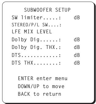
This menu, also reached from the MAIN screen, allows you to optimize the RSP-985 for your particular subwoofer. The settings in this menu may be considered to be "advanced" and need not be adjusted unless specifically desired.
SW LIMITER: The wide dynamic range and impressive bass effects of today's source material can overload a subwoofer. This setting allows you to limit the level of the signal sent to the subwoofer. Go to the limiter menu by highlighting the SW LIMITER line and pressing ENTER. An instruction menu appears and a low frequency noise signal is sent to the subwoofer (or LARGE speakers if no subwoofer is present). Adjust the noise level with the VOL buttons until you just begin to hear distortion from the speakers. Press the ENTER button to set the limiter at this level. Press BACK to return.
STEREO/P/L SW: This setting allows you to override the standard bass management in STEREO, PRO LOGIC, and DSP MUSIC modes when LARGE front speakers are selected. Select YES to have a subwoofer active with LARGE front speakers in these modes. Select NO if you don't have a subwoofer. Select NORMAL for the standard automatic bass management in all modes.
LFE MIX LEVEL: This setting determines the relative signal level of the LFE (Low Frequency Extension) channel (the .1 channel) relative to the five full-range channels. It is factory set according to the standards of Dolby Labs, DTS Technology, and THX Lucasfilm. The adjustment may be varied for each surround mode according to personal taste, if desired.
The LFE content of DTS encoded movies is mixed differently than DTS encoded music. For DTS movies, the LFE MIX LEVEL should be set to 10dB for correct THX playback. For DTS music, the level should be set to 0db. THX should not be activated for music playback. For Dolby Digital movies, the LFE MIX LEVEL should be set to 10db for proper playback in DOLBY DIGITAL and THX modes.
Once you have completed the subwoofer settings for all of your speakers, return to the MAIN menu by pressing the BACK button.
Factory Default Menu
Reset to factory default settings?
YES ENTER
NO = BACK
The final menu that can be reached from the SYSTEM SETUP screen is the FACTORY DEFAULT menu, which resets all system configuration settings to the factory supplied settings.
Note: Resetting to factory default settings will erase all stored settings including delay settings, speaker settings, balance settings, input settings and more. You will lose ALL system configuration settings. Be certain that you wish to do so before resetting the factory defaults.
To reset the factory defaults, press the ENTER button. This will take you to a confirmation screen where you will have a chance to confirm your decision by pressing ENTER a second time.
To return to the SYSTEM SETUP screen without resetting the factory defaults, press the BACK button.
RSP-985 Specifications
Audio
Total Harmonic Distortion (10 Hz - 70 kHz): <0.03%
Intermodulation Distortion (60 Hz: 7 kHz): <0.03%
Frequency Response (line level): 20Hz - 20kHz, ± 1 dB
Signal to Noise Ratio (IHF "A" weighted): 100 dB (Stereo) 90 dB (Dolby Digital, dts)
Gain/Input Impedance
Analog Gain:
10dB/47 kohms
Digital:
0.5V/-20dBf
Tone Controls (Bass/Treble): ±6 dB at 50 Hz/15 kHz
Video
Frequency Response: 3 Hz-10 MHz, ±3 dB
Signal to Noise Ratio: 45 dB
Input Impedance: 75 ohms
Output Impedance: 75 ohms
Power Consumption: 46 watts
Power Requirements (AC): 115 volts, 60Hz (USA version)
230 volts, 50Hz (Europe version)
Weight: 7.0 Kg/15.4 lb.
Dimensions (W× H× D) 440x121x329mm
173 / 8'' × 47 / 8'' × 13''
All specifications are accurate at the time of printing.
Rotel reserves the right to make improvements without notice.
Rotel and the Rotel HiFi logo are registered trademarks of The Rotel Co, Ltd., Tokyo, Japan.
DTS is a registered trademark of Digital Theater Systems.
Manufactured under license from Dolby Laboratories Licensing Corporation. "Dolby", "Pro Logic", and the double-D symbol are trademarks of Dolby Laboratories Licensing Corporation. Confidential unpublished works © 1992 - 1997 Dolby Laboratories, Inc. All rights reserved.
THX Ultra™ and the THX Ultra logo are registered trademarks of Lucasfilms, Ltd.
RSP-985
North Reading, MA 01864-2699
USA
Phone: +1 978-664-3820
Fax: +1 978-664-4109
Rotel Europe
Meadow Road
Worthing, West Sussex BN11 2RX
England
Phone: +44 (0)1903 524 813
Fax: +44 (0)1903 524 831
Rotel Deutschland
Kleine Heide 12
- WARNING:
- Contents
- About Rotel
- Getting Started
- RSP-985 Key Features
- About the THX Ultra™ System
- Unpacking the RSP-985
- Placement
- Front Panel Controls
- Standby LED 3
- Standby Switch 2
- Remote Sensor 1
- Master Volume Control 4
- Tone Controls 6
- Listening Input Source Buttons 11
- Channel Input 9
- Tape Monitor 8
- Recording Input Source Buttons 10
- Surround Sound Mode LEDs 5
- Mode Button
- RR-939 Remote Control
- Programming the RR-939
- Power Button 28
- Volume Buttons
- Mute Button (remote only) 29
- Input Select Buttons 33
- CH Button 36
- Surround + Button 30
- Movie Filter/THX (remote only) 35
- Numeric Buttons (remote only) 32
- On-Screen Button (remote only) 34
- DOWN/UP Buttons (remote only) 31
- Enter Button (remote only) 38
- Back Button (remote only) 37
- Rear Panel Input Connections
- RCA Audio and Video Inputs 12
- All RCA-type connections on the RSP-985 follow these standard color codes:
- S-Video Source Inputs 23
- [See Figure 5]
- Digital Audio Inputs 19
- Channel Audio Input 16
- RCA Tape Monitor Inputs 14
- External In Jack
- Rear Panel Output Connections
- RCA Audio and Video Outputs 13
- [See Figure 4]
- S-Video Outputs 24
- Main Processor RCA Audio Outputs 18
- [See Figure 3]
- Main Processor 25-pin Audio Outputs 17
- TV/Monitor Video Outputs 22
- Tape Monitor Audio Outputs 14
- Rear Panel AC Power Connections
- AC power 21
- AC Convenience Outlets
- Zone 2 Connection and Operation
- Zone 2 Power On/Off Operation
- Zone 2 Audio Outputs 15
- [See Figure 6]
- Remote External Sensor/Repeater Jacks
- On-Screen Display and System Configuration
- Navigation Buttons 27 31 34 37 38
- Start-up Screen
- System Status Screen
- Main Menu Screen
- Dolby Digital Setup Menu
- Input Setup Menu
- INPUT SETUP
- System Setup Menu
- SYSTEM SETUP
- ZONE 2 AUTO-MUTE
- Speaker Setup Menu
- SPEAKER SETUP
- Delay Setup Menu
- Balance Setup Menu
- Subwoofer Setup Menu
- Factory Default Menu
- RSP-985 Specifications
- Audio
- Video
- RSP-985
Brand : ROTEL
Model : RSP-985
Category : Audio Preamplifier