
HCN63 - Range hood ACEC - Free user manual and instructions
Find the device manual for free HCN63 ACEC in PDF.
| Brand | ACEC |
| Model | HCN63 |
| Product type | Cooker hood |
| Use | Extraction or recirculation (charcoal filter) |
| Minimum height above cooking surface | 65 cm |
| Dimensions (approx.) | Width 60 cm, depth 50 cm |
| Power supply | 220-240 V ~ 50 Hz |
| Number of speeds | 3 (low, medium, high) |
| Lighting | Fluorescent lamp 15 W or 2 lamps 40 W (E14) |
| Controls | Hidden control panel (switches for light, fan and speed) |
| Metal grease filters | Dishwasher-safe or hand wash; clean every 2 months |
| Charcoal filter | Not washable, replace every 4 months (in recirculation mode) |
| Air outlet diameter | 100 mm or 120 mm (adaptable) |
| Main material | Stainless steel |
| Safety | Do not flambé under the hood; do not leave frying unattended |
| Noise level | Varies with speed; low at position 1 |
Frequently Asked Questions - HCN63 ACEC
User questions about HCN63 ACEC
0 question about this device. Answer the ones you know or ask your own.
Ask a new question about this device
Download the instructions for your Range hood in PDF format for free! Find your manual HCN63 - ACEC and take your electronic device back in hand. On this page are published all the documents necessary for the use of your device. HCN63 by ACEC.
USER MANUAL HCN63 ACEC
INSTALLATION, USE AND MAINTENANCE HANDBOOK
INSTRUCTIES VOOR MONTAGE, GEBRUK EN ONDERHOUD
MANUEL D'INSTRUCTIONS POUR L'INSTALLATION, L'EMPLOI ET L'ENTRETION
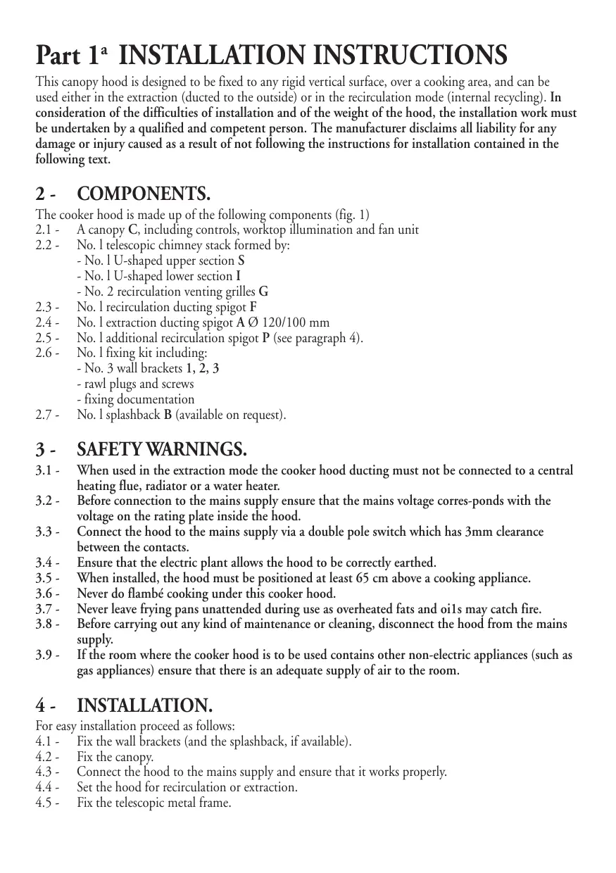
This canopy hood is designed to be fixed to any rigid vertical surface, over a cooking area, and can be used either in the extraction (ducted to the outside) or in the recirculation mode (internal recycling). In consideration of the difficulties of installation and of the weight of the hood, the installation work must be undertaken by a qualified and competent person. The manufacturer disclaims all liability for any damage or injury caused as a result of not following the instructions for installation contained in the following text.
2 - COMPONENTS.
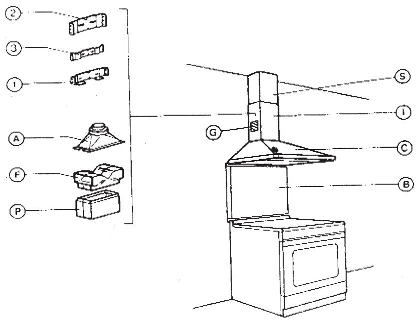
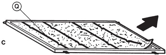
The cooker hood is made up of the following components (fig. 1)
2.1 - A canopy C, including controls, worktop illumination and fan unit
2.2 - No.1 telescopic chimney stack formed by:
- No. 1 U-shaped upper section S
- No.1 U-shaped lower section I
- No. 2 recirculation venting grilles G
2.3 - No.1 recirculation ducting spigot F
2.4 - No.1 extraction ducting spigot A 0 120/100 mm
2.5 - No.1 additional recirculation spigot P (see paragraph 4).
2.6 - No.1 fixing kit including:
- No. 3 wall brackets 1, 2, 3
- rawl plugs and screws
- fixing documentation
2.7 - No. I splashback B (available on request).
3 - SAFETYWARNINGS.
3.1 - When used in the extraction mode the cooker hood ducting must not be connected to a central heating flue, radiator or a water heater.
3.2 - Before connection to the mains supply ensure that the mains voltage corresponds with the voltage on the rating plate inside the hood.
3.3 - Connect the hood to the mains supply via a double pole switch which has 3mm clearance between the contacts.
3.4 - Ensure that the electric plant allows the hood to be correctly earthed.
3.5 - When installed, the hood must be positioned at least 65~cm above a cooking appliance.
3.6 - Never do flambe cooking under this cooker hood.
3.7 - Never leave frying pans unattended during use as overheated fats and oils may catch fire.
3.8 - Before carrying out any kind of maintenance or cleaning, disconnect the hood from the mains supply.
3.9 - If the room where the cooker hood is to be used contains other non-electric appliances (such as gas appliances) ensure that there is an adequate supply of air to the room.
4 - INSTALLATION.
For easy installation proceed as follows:
4.1 - Fix the wall brackets (and the splashback, if available).
4.2 - Fix the canopy.
4.3 - Connect the hood to the mains supply and ensure that it works properly.
4.4 - Set the hood for recirculation or extraction.
4.5 - Fix the telescopic metal frame.
4.1 - Fixing the wall brackets (and splashback)
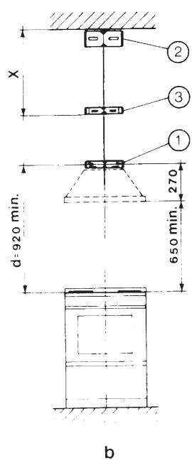
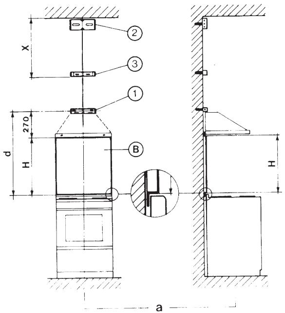
Ref. to Fig. 2 a-b
1 - Draw a vertical line on the wall from the centre of the cooking appliance up to the ceiling, using a marking pen. This is to ensure the correct vertical alignment of many components.
2 - Fixing the wall bracket No. 1:
a - put the bracket I to the wall, aligning its marked centre across the vertical line, ensuring that the distance between the centres of the holes and the cooking area is as follows :
1 - when the splashback is to be installed: d = 270mm + Hmm , where H is the height of the visible part of the splashback. As the splashback can be of different heights, the correct H figure can only be obtained by measuring the actual height of the splashback to be fitted.
2 - without splashback: d = 920 mm minimum.
Note: ensure that the wall bracket (l) is levelled. The hood can be aligned or adjusted in height by rotating the adjustment screws (see below).
b - mark on the wall the centres of the two keyholes of the bracket.
3 - Fixing the wall bracket No. 2:
a - Put the bracket No. 2 to the wall at about 1 - 2mm from the ceiling or from the maximum height required, paying attention to the correct vertical alignment.
b - mark on the wall the centres of the two keyholes of the bracket.
4 - Fixing the wall bracket No. 3:
a - Put the wall bracket No. 3 to the wall, paying attention to the correct vertical alignment at a X distance measured as in Fig. 2 a-b. The X distance must equal the height of the U-shaped upper section S, and can vary according to the different heights of this section.
b - Mark on the wall the centres of the two keyholes of the bracket No. 3.
5 - Pilot drill all the hole positions as marked on the wall using a 8mm drill. Fix the wall brackets 1 - 2 - 3 using the 8mm rawl plugs and screws supplied.
6 - Splashback (if available).
When the splashback F is to be fitted, the distance between the cooker hood and the cooking appliance will be determined by the height of the splashback. The splashback is to be fitted before positioning the canopy. If the splashback is to be fixed to the wall using both the upper and lower fixing points, care must be taken to ensure that the splashback if fitted at the correct height before placing in position the base cabinet and worktop. Being a rather complicated operation, the fixing of the splashback should be carried out by a qualified or competent person, knowing all the final dimensions of the furniture. If the splashback is to be fixed through only the upper part, proceed as follows :
a - Put the splashback on the worktop as shown on Fig. 2; then hold it against the wall ensuring that it is correctly positioned on the worktop.
b - Mark on the wall the two hole positions which appear on the upper part of the splashback.
c - Pilot drill the hole positions using a 8mm drill and fix the splashback using the 8mm rawl plugs and screws supplied.
d - The installer should ensure that the lower part of the splashback is adequately fixed.
4.2 - Fitting the canopy (Fig. 3).
1 - Rotate halfway the two screws R positioned on the hanging lugs of the canopy.
2 - Hook the canopy on to the wall bracket 1 ensuring that the two lugs of the bracket are fitted on the keyhole fixing points of the canopy and push down as allowed by the adjustment screws R.
3 - The canopy can be aligned or adjusted in height using the two adjustment screws R.
4.3 - Electrical connection and working test.
1 - The safety measures 3.2, 3.3 and 3.4 of paragraph 3 are to be strictly observed.
2 - Once the electrical connection has been completed, check that worktop illumination, motor and speeds work properly.
4.4 - Ducting or Recirculation fitting.
1 - Ducting fitting:
a - The cooker hood can be ducted to the outside using either a rigid or a flexible duct of 100 or 120 mm diameter. The choice should be made by the installer.
b - The ducting spigot supplied has an air outlet of 100mm diameter. To adapt to 120mm diameter cut along the slotted line as shown on Fig. 4, using a proper knife.
c - Remove the two screws on top of the canopy and secure the spigot (Fig. 5); fit the spigot A on the rectangular air outlet on the top of the canopy and secure the spigot to the canopy using the two screws.
d - Connect (Fig. 5) the rigid/flexible duct to both the ducting spigot A and to the wall outlet using suitable clamps (not supplied). The installer should ensure that the ducting material is available.
e - If the hood is provided with the charcoal filter fitted, the filter should be removed (see part 2, paragraph 3 3.2b.)
2 - Recirculation fitting:
a - When the hood is installed in the recirculation mode, the air is recirculated into the kitchen through the two venting grilles located on both sides of the lower U-shaped section. The two grilles can be positioned at two different heights (Fig. 6 and 7).
b - Lower position (Fig. 6): Fit the recirculation spigot F to the rectangular outlet on top of the canopy and push it down ensuring that the four lugs are fitted into the holes.
c - Upper position (Fig. 7): Fit the additional spigot P to the rectangular outlet on top of the canopy and push it down ensuring that the four lugs fit into the holes. Then fit the recirculation spigot F on the additional spigot P .
d - Fit the charcoal filter inside the canopy see part 2, paragraph 3 3.3b.
NOTE - Do not fit the two venting grilles to the chimney stack: the grilles are to be fitted only when the chimney stack has been positioned.
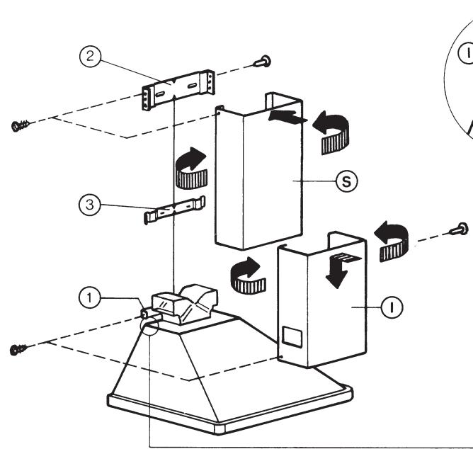
4.5 - Fitting the telescopic chimney stack (Fig. 8).
The chimney stack is formed using the two U-shaped sections and it is adjustable for different heights.
1 - To fit the upper section S first widen the two sides of the section slightly so that they can be clamped to the wall brackets 2 and 3 and then ensure that they are correctly ga-stened. The upper section is fixed to the wall bracket 2 with its upper corners. Secure the upper section to the bracket 2 using two screws provided with the fixing kit.
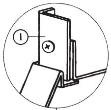
2 - The lower section I of the chimney stack can be fixed in a similar way between the wall brackets 1 and 3 and the wall, paying attention to fit the lower part of the section into the recess of the canopy (see close-up). Then fix the lower section I to the wall bracket I using the two remaining self tapping screws. NOTE - The upper S and lower I sections are fixed to the wall bracket in the middle 3 through a spring and the connection is made by pushing both sections vigorously toward the centre.
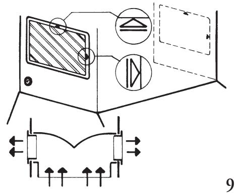
3 - Fit the two venting grilles, one to either side of the chimney stack. The grilles are marked with two arrows and should be fitted so that one arrow is pointing upwards and the other forward away from the wall. When the hood is to be used in the recirculation mode ensure that both grilles fit properly to the recirculation spigot F (Fig. 9).
Part 2a OPERATION AND MAINTENANCE INSTRUCTIONS
1 - SAFETYWARNINGS.
It is most important that all the warnings shown in parag. 3 of the Installation instructions are strictly observed. Moreover pay special attention to the following warnings during the use and maintenance of the cooker hood.
1.1 - The grease filters and the charcoal filter should be cleaned or replaced as recommended by the manufacturer or more frequently if the hood is used consistently (over 4 hours per day).
1.2 - When using a gas hob in conjunction with the cooker hood, never leave the burners uncovered while the hood is in use; when removing the pans either turn the hob off or keep the flame to a minimum if it is only for a few minutes and under supervision.
1.3 - Always ensure that the flame does not overflow from under the pans; this will save energy and will avoid a dangerous concentration of heat.
1.4 - Do not use the appliance in any incorrect way: this hood has been designed only to reduce the smells of cooking in the kitchen.
2 - OPERATION.
2.1 - The cooker hood functions are located in a concealed control panel on the right hand side of the canopy, behind the front trim. To gain access to the control panel apply slight pressure to the control panel back and release. To relocate the control panel in its concealed position just push it back upwards.
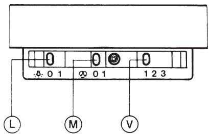
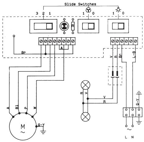
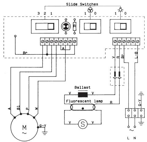
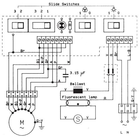
2.2 - The cooker hood can be operated as follows (Fig. 11):
- the switch L, marked with the lamp symbol, controls the worktop illumination;
- the switch M, marked with the fan symbol, controls the power to the fan motor (0-1);
- the switch V, marked 1-2-3, controls the fan speed:
- position 1: low speed, should be selected when simmering or using only one pan; the noise level is kept to the minimum.
- position 2: medium speed, should be selected for normal cooking. This speed offers the best ratio between air capacity and noise level.
- position 3: top speed, should be selected when frying or cooking food with strong odours, even for a long period.
3 - MAINTENANCE.
Regular maintenance and cleaning will ensure good performance and reliability, while extending the working life of the hood. Special attention should be paid to the grease filters and to the charcoal filter when the hood is used in the recirculation mode.
3.1 - Metal grease filters.
a-Cleaning:
The metal grease filters should be cleaned every two months with normal usage and can be cleaned in a dishwasher or by hand using mild detergent or liquid soap.
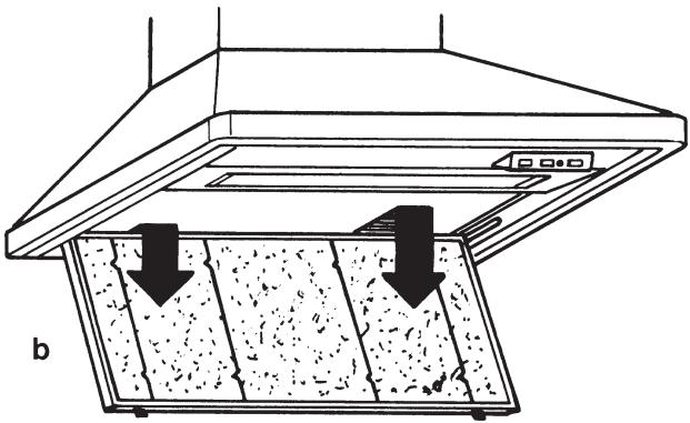
b - Replacement:
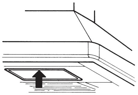
The metal grease filter panels are easily removed, one at a time, by applying slight inward pressure to the actuators to release the securing bolts. Care should be taken to support the filter with one hand while releasing the securing bolts with the other hand (Fig. 13). The filter panels should be refitted with bolt side facing downwards.
3.2 - Thin synthetic filter.
On certain models the metal grease filters are replaced with a lower grille panel containing a paper filter with saturation indicators.
a - Cleaning:
The paper filter visible through the perforated metal grease filter tray cannot be washed and should be replaced when the white areas between the violet dots turn brown.
b - Replacement:
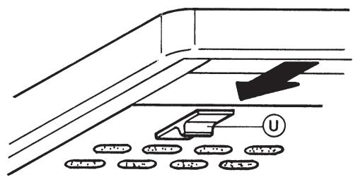
To remove the filter for subsequent replacement first open the metal grille panel (Fig. 14a) to the stop position. To remove the metal grille panel slide the right hand side of the panel forward until the hinge pin comes away from the recess in the side casing (Fig. 14b). The filter is easily removed from the grille by pushing the wire clips to one side and removing (Fig. 14c). Replace the filter making sure that the saturation indicators face downwards. Replace by reversing the operation ensuring that the lower grille is securely fastened to the side casing.
3.3 - Charcoal filter.
a - In the recycling mode the charcoal filter absorbs smells and odours. The charcoal filter cannot be cleaned and should be replaced at least every 4 months or more frequently if the hood is used consistently.
b - To replace the charcoal filter first remove the metal grease filters (or metal grille) and then unscrew the two thumb screws located on each side of the charcoal filter.
3.4 - Worktop illumination.
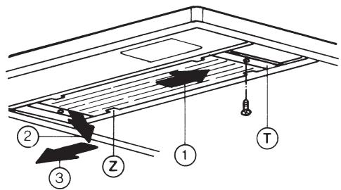
A 15W fluorescent strip lamp ensures the illumination of the worktop. To replace the strip lamp operate as follows (Fig. 12):
a - Remove the plastic cover T near the control box. The glass strip is kept in its position by the retaining lugs Z.
b - Move the glass strip towards the control box until the opposite end is free (arrow 1). Pull the glass strip slightly down (arrow 2) and then move it back the opposite direction (arrow 3) until the glass strip can be removed. The strip lamp can be removed by rotating the lamp a quarter turn. Replace by reversing the operations. On certain models the illumination of the worktop is ensured by 2 lamps of 40W (E 14).
3.5 - Cleaning.
The metal work, both inside and outside, should be cleaned regularly by using mild household detergents or liquid soap. Care should be taken not to use abrasive cleaning materials, especially when cleaning stainless steel surfaces.
1
2
| 3 | 4 |
| 5 | |
| 6 | 7 |
8
10
11
12

a
- - COMPONENTS.
- - SAFETYWARNINGS.
- - INSTALLATION.
- - Fixing the wall brackets (and splashback)
- - Fitting the canopy (Fig. 3).
- - Electrical connection and working test.
- - Ducting or Recirculation fitting.
- - Ducting fitting:
- - Recirculation fitting:
- - Fitting the telescopic chimney stack (Fig. 8).
- Part 2a OPERATION AND MAINTENANCE INSTRUCTIONS
- - SAFETYWARNINGS.
- - OPERATION.
- - MAINTENANCE.
- - Metal grease filters.
- - Thin synthetic filter.
- - Charcoal filter.
- - Worktop illumination.
- - Cleaning.
Brand : ACEC
Model : HCN63
Category : Range hood