
W2408 - Monitor COMPAQ - Free user manual and instructions
Find the device manual for free W2408 COMPAQ in PDF.
| Product Type | LCD Monitor |
| Brand | COMPAQ |
| Model | W2408 |
| Screen Size | 24 inches (61 cm) |
| Native Resolution | 1920 x 1080 (Full HD) |
| Aspect Ratio | 16:9 |
| Connectivity | VGA, DVI-D |
| Built-in Speakers | Yes (2 x 2W) |
| Power Consumption | 45 W (typical), < 1 W (standby) |
| Power Supply | 100-240 V AC, 50/60 Hz |
| Dimensions (with stand) | 567 x 400 x 220 mm |
| Weight (with stand) | 5.2 kg |
| Viewing Angle | 170° horizontal, 160° vertical |
| Response Time | 5 ms (gray to gray) |
| Brightness | 300 cd/m² |
| Contrast Ratio | 1000:1 (static) |
| Maintenance | Clean with a soft, dry cloth. Do not use abrasive products. |
| Safety | Install on a stable surface. Ensure adequate ventilation. |
| Repairability | Spare parts available through authorized after-sales service. |
| Standards | ENERGY STAR certified, compliant with Class B of the Canadian Interference-Causing Equipment Regulations. |
Frequently Asked Questions - W2408 COMPAQ
User questions about W2408 COMPAQ
0 question about this device. Answer the ones you know or ask your own.
Ask a new question about this device
Download the instructions for your Monitor in PDF format for free! Find your manual W2408 - COMPAQ and take your electronic device back in hand. On this page are published all the documents necessary for the use of your device. W2408 by COMPAQ.
USER MANUAL W2408 COMPAQ
The only warranties for HP products and services are set forth in the express warranty statements accompanying such products and services. Nothing herein should be construed as constituting an additional warranty. HP shall not be liable for technical or editorial errors or omissions contained herein.
HP assumes no responsibility for the use or reliability of its software on equipment that is not furnished by HP.
This document contains proprietary information that is protected by copyright. No part of this document may be photocopied, reproduced, or translated to another language without the prior written consent of HP.
Hewlett-Packard Company
10955 Tantau Avenue
Cupertino, California 95014-0770
USA
Copyright © 2006-2008 Hewlett-Packard Development Company, L.P.
Microsoft and Windows are U.S. registered trademarks of Microsoft Corporation.
Adobe and Acrobat are trademarks of Adobe Systems Incorporated.
ENERGY STAR and the ENERGY STAR logo are U.S. registered marks of the United States Environmental Protection Agency.
Bluetooth is a trademark owned by its proprietor and used by Hewlett-Packard Company under license.
HP supports lawful use of technology and does not endorse or encourage the use of its products for purposes other than those permitted by copyright law.
The information in this document is subject to change without notice.
Notational Conventions
The following section describes notational conventions used in this document.
Notes, Cautions, andWarnings
Throughout this guide, blocks of text may be accompanied by an icon. These blocks are notes, cautions, and warnings, and they are used as follows:

WARNING: Indicates that failure to follow directions could result in bodily harm or loss of life.

CAUTION: Indicates that failure to follow directions could result in damage to equipment or loss of information.

NOTE: Indicates additional information.
Notational Conventions. 1-iii
Notes, Cautions, andWarnings 1-iii
1 Product Features
HP LCD Monitors 1-1
Features. 1-1
Base Designs 1-2
2 Safety and Maintenance Guidelines
Important Safety Information 2-1
Safety Precautions 2-1
Maintenance Guidelines 2-2
Cleaning the Monitor 2-2
3 Setting Up the Monitor
Unpacking the Monitor 3-1
Installing the Monitor 3-1
Installing on a Desktop. 3-1
Unfolding the double-hinged monitor 3-2
Assembling the cantilever base 3-3
Assembling the column base 3-3
Wall-Mounting the Monitor (Mounting Fixture not Supplied) 3-4
Preparing the double-hinged monitor for wall-mounting. 3-4
Preparing the cantilever-base monitor for wall-mounting 3-5
Preparing the column-base monitor for wall-mounting 3-6
Reinstalling the desktop pedestal and base for the monitor 3-6
Connecting the VGA (Analog) or DVI-D (Digital) Cable 3-7
To connect the VGA cable 3-7
To connect the DVI-D cable 3-7
Connecting the HDMI Cable. 3-7
Audio and Video Cables and Adapters 3-8
3-9
Connecting the USB Hub Cable 3-9
Connecting USB Devices to the Monitor 3-9
Connecting the Power Cable 3-10
Cable Management 3-11
Adjusting the Tilt. 3-12
Adjusting the Swivel (Select Models Only) 3-13
Adjusting the Height (Select Models Only) 3-13
Pivoting the Monitor (Select Models Only) 3-14
Ambient Light Sensor (Select Models Only) 3-15
Keyboard Parking. 3-15
4 Operating the Monitor
CD Software and Utilities 4-1
4-1
Downloading Updated Drivers from the Internet. 4-1
Using the Auto-Adjustment Function 4-1
My Display Software. 4-2
Front-Panel Controls 4-3
Using the Onscreen Display (OSD) 4-3
OSD Menu Selections 4-4
Selecting Video Input Connectors 4-7
Identifying Monitor Conditions 4-7
Adjusting Screen Quality. 4-7
Optimizing Analog Video 4-8
Power-Saver Feature 4-8
High-Bandwidth Digital Content Protection (HDCP) 4-8
5 Preparing the Monitor for Shipping
Removing the Monitor Base 5-1
Removing the cantilever base 5-1
Removing the column base 5-2
Folding the Double-Hinged Monitor 5-3
A Troubleshooting
Solving Common Problems A-1
Getting Support from hp.com. A-2
Preparing to Call Technical Support A-2
Locating the Rating Label A-2
B Technical Specifications
HP LCD Monitors B-1
Preset Video Modes B-7
LCD Monitor Quality and Pixel Policy B-12
Power Cord Set Requirements B-12
C Agency Regulatory Notices
Modifications C-1
Cables. C-1
Federal Communications Commission Notice. C-1
Declaration of Conformity for Products Marked with FCC Logo, United States Only . . . . . . . C-1
Materials Disposal C-2
Canadian Notice C-2
Avis Canadien C-2
European Union Regulatory Notice. C-2
Disposal of Waste Equipment by Users in Private Households in the European Union . . . . . . . C-2
Japanese Notice C-3
Japanese Power Cord Notice. C-3
Japanese Material Content Declaration. C-3
Korean Notice C-3
EPA Energy Star® Compliance C-3
HP Recycling Program. C-3
HP LCD Monitors
The HP LCD (liquid crystal display) monitors have an active matrix, thin-film transistor (TFT) screen. This guide discusses the following models:
vp15 LCD Monitor
vp17 LCD Monitor
vp19 LCD Monitor
FP1707 LCD Monitor
■ WF1907 LCD Monitor
w1707 LCD Monitor
w1907 LCD Monitor
w2007 LCD Monitor
w2207 LCD Monitor
w2216 LCD Monitor
■ w2408 LCD Monitor
Features
Large diagonal viewable-area display
Optimum resolution:
vp15: 1024 × 768 @ 60 Hz
vp17, vp19, and FP1707: 1280 × 1024 @ 60 Hz
□ WF1907, w1707, and w1907: 1440 × 900 @ 60 Hz
w2007, w2216, and w2207: 1680 x 1050 @ 60 Hz
□ w2408: 1920 x 1200 @ 60 Hz
Plus full-screen support for lower resolutions
Video inputs supported:
VGA analog signal
DVI digital signal (select models only)
High-definition multimedia interface (HDMI) (select models only)
Fast response time, providing better experience for gaming and graphics
Easy viewing from a sitting or standing position, or while moving from one side of the monitor to the other
Tilt adjustment
Height adjustment (select models only)
Pivot adjustment, for landscape or portrait viewing (select models only)
- Removable pedestal and Video Electronics Standards Association (VESA) standard mounting holes for flexible mounting solutions, including wall-mounting
Security lock slot for a Kensington lock security cable (security cable sold separately)
Plug and Play capability, if supported by your computer system
■ On-screen display (OSD) adjustments for ease of setup and screen optimization (choose English, Simplified Chinese, French, German, Italian, Spanish, Dutch, or Japanese)
- Swiveling monitor, allowing a usable range of motion (select models only)
■ Built-in stereo speakers, front- or rear-facing depending on model
Universal Serial Bus (USB) 2.0 ports to use with USB devices (select models only have two or four ports)
Ambient light sensor (select models only)
Keyboard parking (select models only)
Power Saver to reduce energy consumption
Quick View settings display
CD includes (select models only):
Drivers (select models only)
Auto-adjustment software
My Display software (select models only)
Documents
Adobe® Acrobat® Reader
Varied monitor base designs
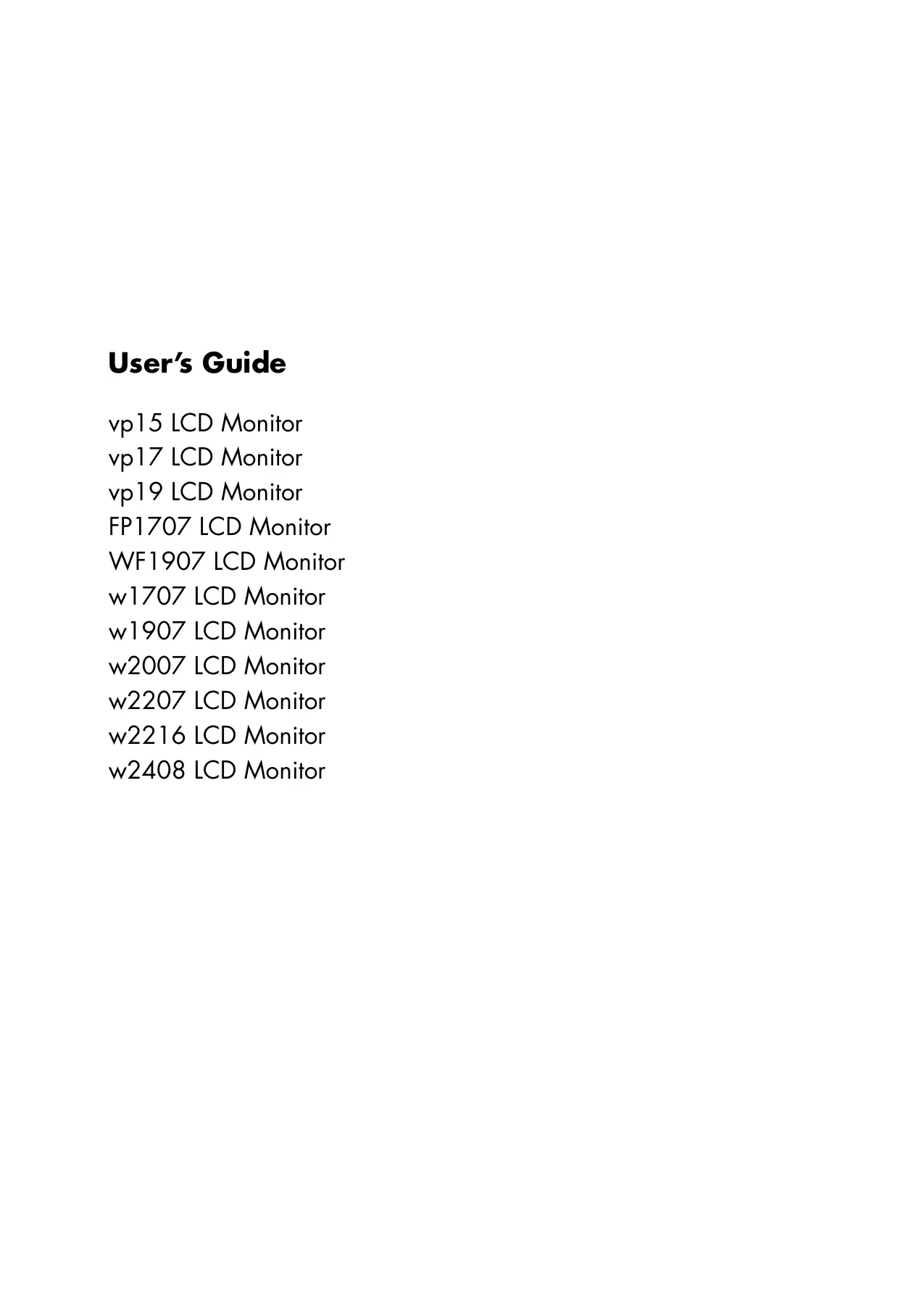
Base Designs
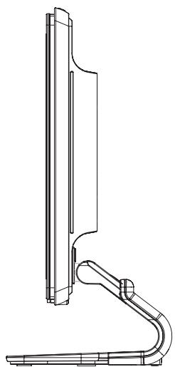
Cantilever base
Column base
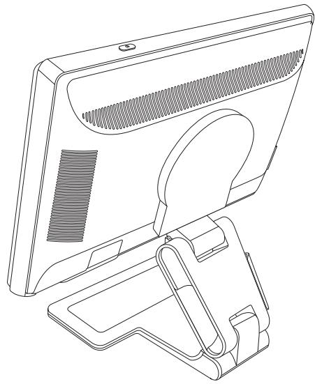
Double-inged base
Safety and Maintenance Guidelines
Important Safety Information
The power cord is designed for use with your monitor. To use a different cord, use only a power source and connection compatible with this monitor.

WARNING: Always connect your monitor, the computer, and other equipment to a grounded (earthed) power outlet. To reduce the risk of electric shock or damage to your equipment, do not disable the power cord grounding feature. The grounding plug is an important safety feature.

WARNING: For your safety, be sure that the grounded power outlet you plug the power cord into is easily accessible to the operator and located as close to the equipment as possible. To disconnect power from the equipment, unplug the power cord from the power outlet by grasping the plug firmly. Never pull on the cord.

CAUTION: To protect your monitor, as well as your computer, connect all power cords for your computer and its peripheral devices (such as a monitor, printer, or scanner) to a surge protection device such as a power strip with surge protection or uninterruptible power supply (UPS).
Not all power strips provide surge protection; the power strips must be specifically labeled as having this ability. Use a power strip whose manufacturer offers a damage replacement policy, so you can replace your equipment if surge protection fails.
Safety Precautions
Use only a power source and connection compatible with this monitor, as indicated on the label/back plate of the monitor.
■ Be sure the total ampere rating of the products connected to the outlet does not exceed the current rating of the electrical outlet, and the total ampere rating of the products connected to the power cord does not exceed the rating of the power cord. Look on the power label to determine the ampere rating (Amps or A) for each device.
Install your monitor near a power outlet that you can easily reach. Disconnect the monitor by grasping the plug firmly and pulling it from the outlet. Never disconnect the monitor by pulling the cord.
- Do not allow anything to rest on the power cord. Do not walk on the cord.
Maintenance Guidelines
To enhance the performance and extend the life of your monitor:
■ Do not open your monitor cabinet or attempt to service this product yourself. If your monitor is not operating properly or has been dropped or damaged, contact your Hewlett-Packard authorized dealer, reseller, or service provider.
Adjust only those controls that are described in the operating instructions.
Turn your monitor off when not in use. You can substantially increase the life expectancy of the monitor by using a screen saver program and turning off the monitor when not in use.
- Keep your monitor in a well-ventilated area, away from excessive light, heat, or moisture.
- Slots and openings in the cabinet are provided for ventilation. These openings must not be blocked or covered. Never push objects of any kind into cabinet slots or other openings.
Unplug the monitor from the power outlet before cleaning. Do not use liquid cleaners or aerosol cleaners.
Do not drop the monitor or place it on an unstable surface.
When removing the monitor base, you must lay the monitor face down on a soft area to prevent it from getting scratched, defaced, or broken.
Cleaning the Monitor
The monitor is a high-quality optical device that requires special care when cleaning. To clean the monitor, follow these steps:
- Turn off the computer and the monitor.
- Unplug your monitor from the power outlet before cleaning.

CAUTION: Do not use benzene, thinner, ammonia, or any volatile substance to clean the monitor screen or cabinet. These chemicals may damage the monitor. Do not use liquid or aerosol cleaners. Never use water to clean an LCD screen.
- Wipe the screen with a dry, soft, clean cloth.
If the screen requires additional cleaning, use an antistatic screen cleaner. - Dust the monitor housing. Use a damp cloth to clean the cabinet.
If the cabinet requires additional cleaning, use a clean cloth dampened with isopropyl alcohol. - Plug in the monitor.
- Turn on the monitor and the computer.
Setting Up the Monitor
Unpacking the Monitor
- Unpack the monitor. Make sure all contents are included. Store the packing box.
- Turn off the computer and other attached devices.
- Determine whether the monitor will be desktop mounted or wall-mounted. See "Installing the Monitor."
- Prepare a flat area to assemble the monitor. You may need a flat, soft, protected area for placing the monitor screen-down while preparing it for installation.
- You need a Phillips screwdriver for preparing the monitor for wall-mounting. You may need a straight-slot screwdriver to secure some cables.
Installing the Monitor
You can install the monitor on a desktop or wall-mount it. Place the monitor in a convenient, well-ventilated location near your computer.
If the monitor will be installed on a:
Desktop or table, see "Installing on a Desktop."
■ Wall, swing arm, or other mounting fixture, see "Wall-Mounting the Monitor (Mounting Fixture not Supplied)."
Connect the monitor cables after you have installed the monitor.
Installing on a Desktop
Follow the instructions for your monitor type.
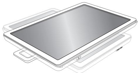
Unfolding the double-inged monitor

WARNING: Do not place the double-inged monitor face down for folding. The base hinge can spring up and cause serious injury or damage.
- With the monitor still in its flat, folded state, set it screen-side up on a flat surface.
- Rotate the screen to the horizontal position (in the figure, the straight arrow is your position in front of the monitor).
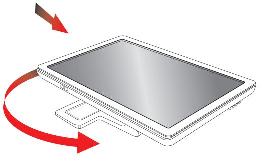
- Holding the base of the monitor, lift up the panel at its top without touching or putting pressure on the screen (3).
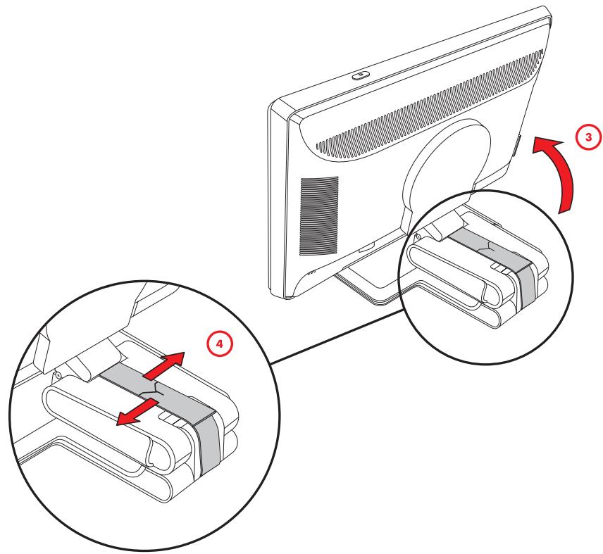
- Remove the shipping strap (do not cut it) (4).
- Put the shipping strap in a safe place, in case you need it to ship the monitor.
- Lift and lower the base hinge for proper viewing.
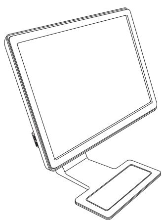
Assembling the cantilever base

CAUTION: The screen is fragile. Avoid touching or applying pressure to the LCD screen; doing so can cause damage.
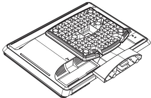
- Set the monitor screen down on a flat, soft, protected surface.
- Align the neck with the monitor base.
- Slide the base until it snaps in place. Make sure the base is securely locked in place.
Attaching the cantilever base
- Lift the monitor to an upright position and place on a flat, stable surface.
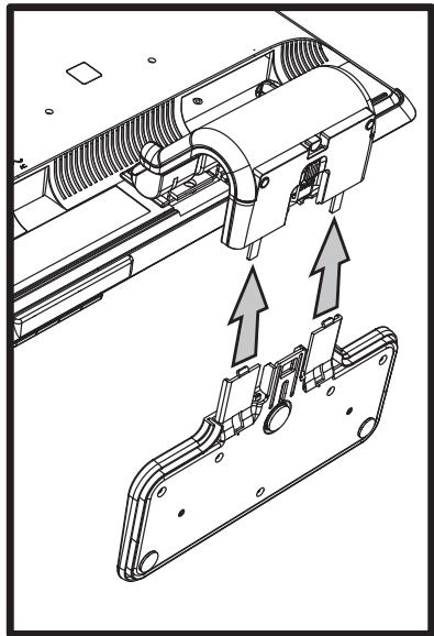
Assembling the column base
- Set the monitor base on a flat, stable surface.
- Lift the monitor, and align the pedestal with the base.
- Lower the monitor until the base snaps in place. Make sure the base is securely locked.
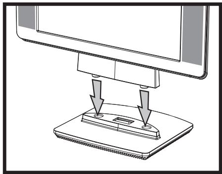
Attaching the column base
Wall-Mounting the Monitor (Mounting Fixture not Supplied)
Before you mount the monitor on a wall, a swing arm, or other mounting fixture, you must remove the monitor base and the pedestal. You will need a Phillips screwdriver. Read the following warning and caution statements before beginning the procedure.

WARNING: To reduce the risk of personal injury or of damage to the equipment, check that the wall-mounting fixture is adequately installed and secured before attaching the monitor. Refer to the instructions supplied with the wall-mounting fixture and check that it is capable of supporting the monitor.
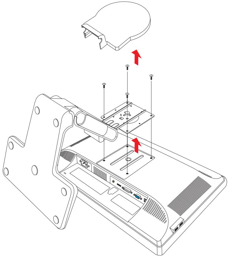
Preparing the double-hinged monitor for wall-mounting

WARNING: Do not place the double-hinged monitor face down for folding. The base hinge can spring up and cause serious injury or damage.
- Disconnect the power cable and any other cables from the monitor.
- Carefully place the monitor face down on a flat, soft surface. This might entail elongating the hinge and tilting the monitor back to ensure the monitor is flat.
- With your fingertips, snap off the VESA cover from the back of the monitor.
- Remove all four screws from the VESA plate.
- Save the removed items (cover, screws, and base) for future use.
- Follow the instructions included with the mounting fixture to ensure that the monitor is safely attached.
The four-threaded mounting holes that are on the back of the panel are compliant with the VESA standard for mounting flat-panel monitors. The 15-inch monitor uses the 75~mm spacing standard, while the other models use the 100~mm spacing standard.
Use the four holes to attach a swing arm or other mounting fixture.
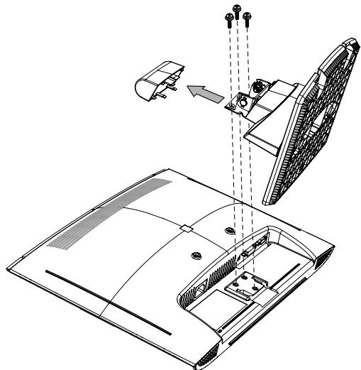
Preparing the cantilever-base monitor for wall-mounting
- Disconnect the power cable and any other cables from the monitor.
- Remove the monitor base. Refer to "Removing the Monitor Base." Keep the monitor panel screen down on a flat, soft area.
- After the base is removed, remove the rubber plug on the neck of the monitor. You will see a screw below the rubber plug and two additional screws on the panel.
- Remove all three screws.
- Remove the neck from the monitor.
- Save the removed items (rubber plug, screws, neck, and base) for future use.
- Follow the instructions included with the mounting fixture to ensure that the monitor is safely attached.
The four-threaded mounting holes that are on the back of the panel are compliant with the VESA standard for mounting flat-panel monitors. The vp15 monitor uses the 75 mm spacing standard, while the other models use the 100 mm spacing standard.
Use the four holes to attach a swing arm or other mounting fixture.
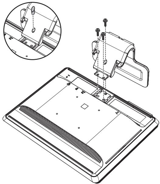
Preparing the column-base monitor for wall-mounting
-
Disconnect the power cable and any other cables from the monitor.
-
With the monitor screen face-down on a flat, soft surface, remove the monitor base. Refer to "Removing the Monitor Base."
-
Remove the hinge cover and set it aside. Three screws and the hinge are exposed.
-
Holding the pedestal so that it cannot fall, remove the single screw that is close to the hinge, and then remove the other two screws. If necessary, move the pedestal, so that all three screws are accessible.
-
Slide the pedestal off the monitor panel.
-
Save the removed items (screws, hinge cover, pedestal, and base) for future use.
-
Follow the instructions that are included with the mounting fixture to ensure that the monitor is safely attached. The four-threaded mounting holes that are on the back of the panel are compliant with the VESA standard for mounting flat-panel monitors. The vp15 monitor uses the 75mm spacing standard, while the other models use the 100mm spacing standard.
Use the four holes to attach a swing arm or other mounting fixture.
Reinstalling the desktop pedestal and base for the monitor
- Remove the mounting fixture.
- Reverse the preceding instructions.
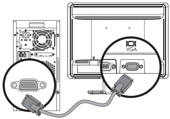
Connecting the VGA (Analog) or DVI-D (Digital) Cable
Use a VGA video cable or a DVI-D video cable (provided with select models). To use DVI, you must have a DVI-compliant graphic card. Connectors are located on the back of the monitor. Be sure the computer and monitor are turned off and unplugged.
Some graphic cards have both a DVI connector and a DVI-to-VGA converter included in the box (select models only). If the monitor has a VGA connector but no DVI connector, use the DVI-to-VGA converter to connect to the computer: Connect the DVI-to-VGA converter to the DVI connector on the computer graphic card, and then connect the VGA cable to the converter and the monitor.
VGA
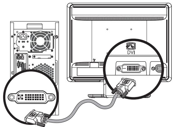
DVI
Connecting the VGA or DVI-D cable—connector locations may vary
To connect the VGA cable
Connect one end of the VGA video cable to the back of the monitor and the other end to the VGA video connector on the computer.
To connect the DVI-D cable
Connect one end of the DVI-D video cable to the back of the monitor and the other end to the DVI video connector on the computer. You can use this cable only if your compute has a DVI-compliant graphic card installed. The monitor DVI-D connector and cable are included with select models only.

NOTE: If you use a DVI-to-HDMI adapter, you must connect the green audio cable to enable the speakers. The signal from the DVI connector is for video only.
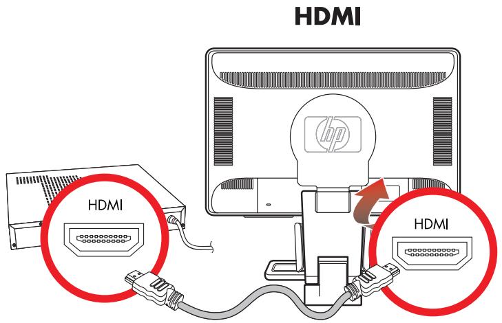
Connecting the HDMI Cable
Connect one end of the HDMI cable (select models only) to the back of the monitor and the other end to any compatible digital audio/video source, such as a set-top box, a DVD player, or a digital television.
Audio and Video Cables and Adapters
The following table shows the cable and adapter types that may be required to connect the monitor to the computer, TV, or set-top box.
The number and type of cables required may vary by model. Some cables and adapters are included for select models only and may be sold separately.
| Cable/Adapter | Name | Description |
| HDMI cable | HDMI transmits an all-digital signal. It is the recommended choice for playback from a DVD or DVR. HDMI is capable of transmitting both uncompressed digital audio and digital video signals, because it has video, audio, and control signals. | |
| DVI cable | DVI transmits an all-digital video signal. | |
| VGA cable | VGA transmits an analog video signal. | |
| DVI-to-VGA adapter | Connects a DVI monitor to a VGA connector on the back of the computer, TV, or set-top box or connects a VGA monitor to a DVI connector on the back of the computer, TV, or set-top box. | |
| DVI-to-HDMI adapter | Connects a DVI monitor to an HDMI connector on the back of the computer, TV, or set-top box or connects an HDMI monitor to a DVI connector on the back of the computer, TV, or set-top box. NOTE: If you use a DVI-to-HDMI adapter, you must connect the green audio cable to enable the speakers. |

NOTE: When using a VGA or DVI signal, you must connect your audio separately because a VGA or DVI signal converts only video data, not audio data. A separate audio connection is not necessary when you use an HDMI signal, because an HDMI signal can convert both video and audio data.
Connecting the Audio Cable
Connect the built-in monitor speakers to the computer by using the audio cable, as shown in the following illustration.
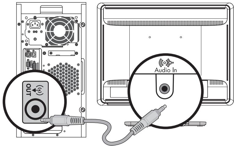
Connecting the audio cables—connector locations may vary
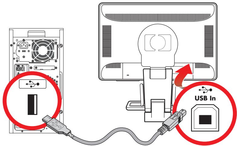
Connecting the USB Hub Cable
Connect the USB hub cable from the computer to the USB In connector on the monitor (select models only have USB capability). This enables USB 2.0 ports on the monitor.
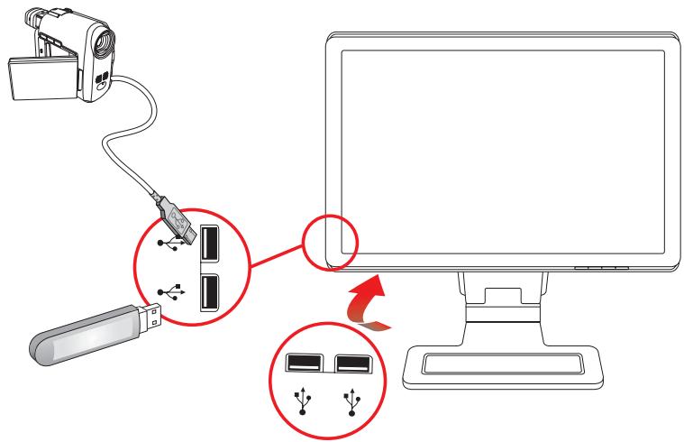
Connecting USB Devices to the Monitor
You can connect two or four USB devices (select models only), such as a USB flash drive or a digital camcorder, to your monitor. Do this only after you have connected the USB hub cable from the computer to the monitor.
Connecting the Power Cable
- Read the warning below.

WARNING: To reduce the risk of electric shock or damage to your equipment:
- Do not disable the power cord grounding plug. The grounding plug is an important safety feature. Plug the power cord into a grounded (earthed) electrical outlet.
■ Be sure that the grounded power outlet you plug the power cord is easily accessible to the operator and located as close to the equipment as possible. A power cord should be routed so that it is not likely to be walked on or pinched by items that are placed upon it or against it. - Do not place anything on power cords or cables. Arrange them so that no one may accidentally step on or trip over them. Do not pull on a cord or cable.
See "Power Cord Set Requirements" in Appendix B for additional information.
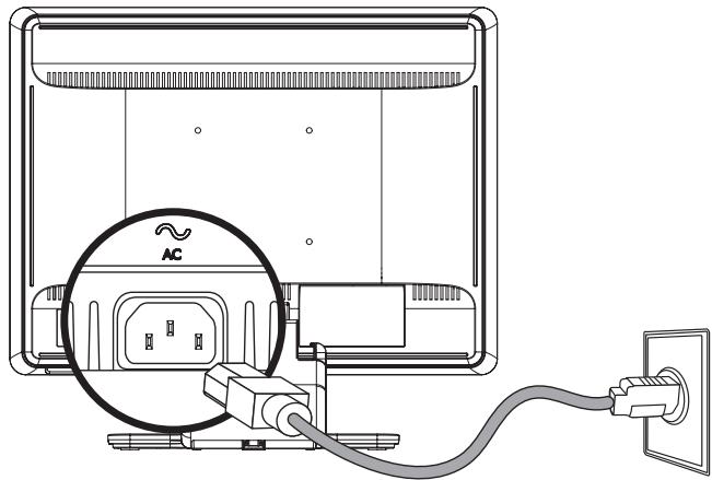
Connecting the power cable
- Connect one end of the power cable to the monitor and the other end to a grounded electrical outlet.
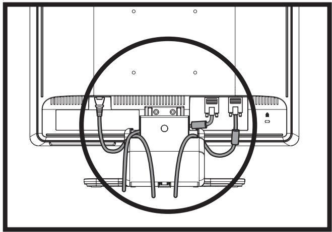
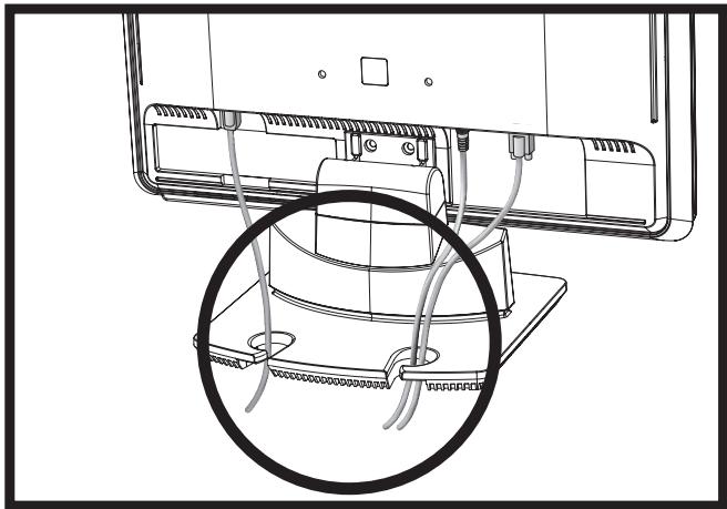
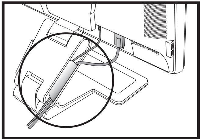
Cable Management
The HP LCD monitors have either two hooks or two cable tunnels on either side for cable management. Cables can be easily secured and are hidden when viewed from the front.

NOTE: If your monitor has the pivot feature, make sure the cords are set loosely enough so they will not pull and disconnect when the monitor is pivoted.
Adjusting the Tilt
For optimal viewing, adjust the screen tilt to your own preference, as follows:
- Face the front of the monitor and hold the base so that you do not topple the monitor while changing the tilt.
- Adjust the tilt by moving the top edge of the monitor either toward or away from you, without touching the screen.
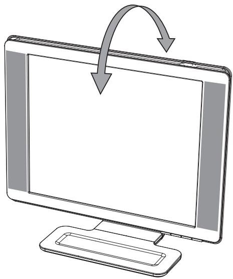

CAUTION: The double-hinged monitor can fall back if the hinge is extended fully and the monitor screen is tilted back too far.
Adjusting the Swivel (Select Models Only)
The HP LCD monitor allows a usable range of motion with the swivel feature.
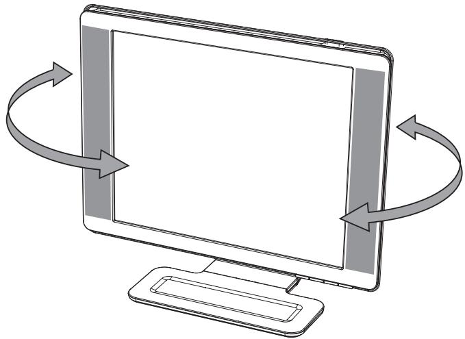

CAUTION: To avoid breakage or other damage, avoid applying pressure to the LCD screen while swiveling it or changing the tilt.
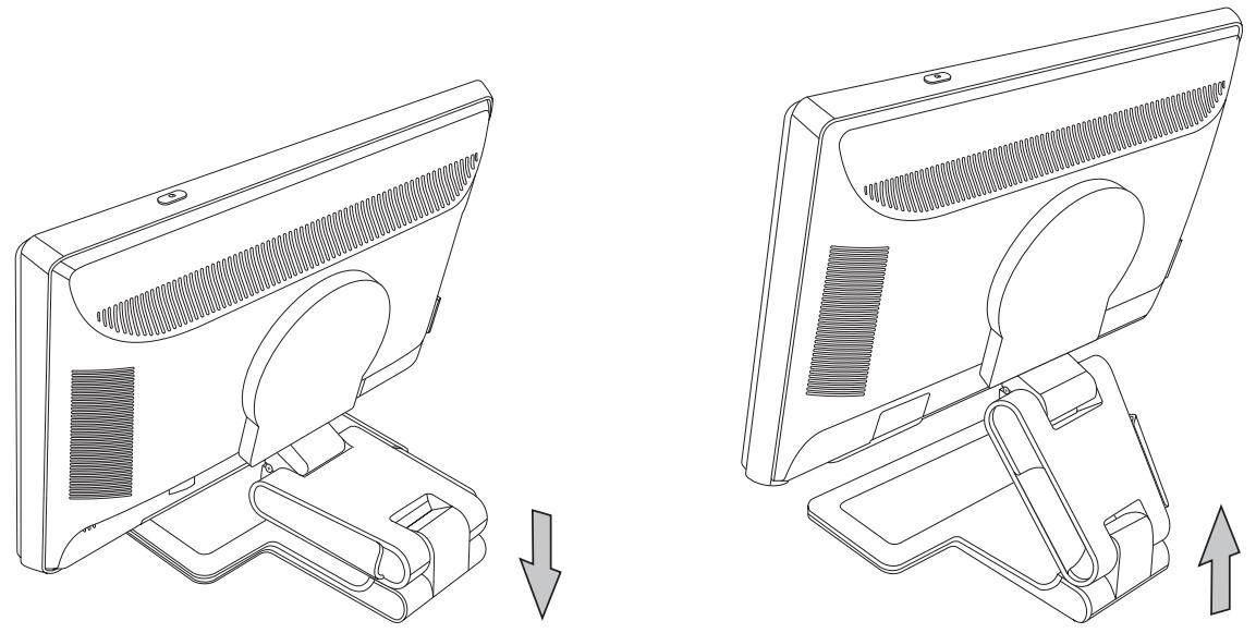
Adjusting the Height (Select Models Only)
The double-hinged monitor adjusts up and down easily by extending or lowering the hinge.
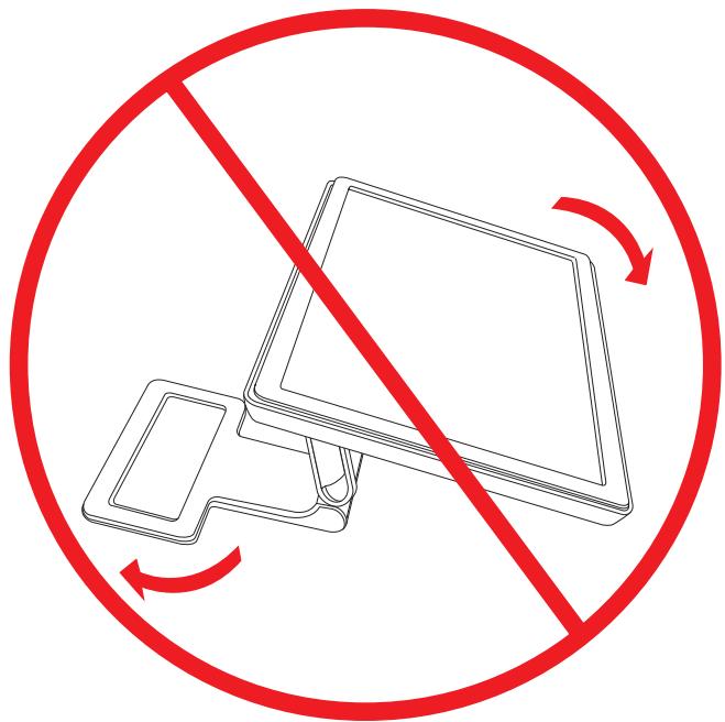
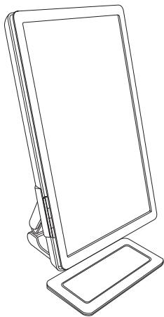
Pivoting the Monitor (Select Models Only)

NOTE: For full functionality of this pivot feature, the My Display software may need to be installed. See "My Display Software" in the Operating the Monitor chapter for information on how to install this software. Some graphics cards support rotating the image of the display automatically.
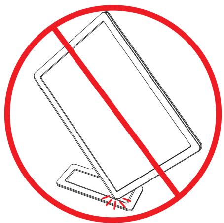
- Facing the monitor and holding its base down, tilt the monitor backward 10 to 30 degrees by pulling the bottom of the screen toward you.
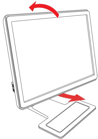

CAUTION: The first step is important—the double-hinged monitor can scratch the base surface if the monitor is not tilted back enough before pivoting it.
- If the monitor is in its landscape position, after it is tilted back, pivot it clockwise to portrait position. If it is in portrait position, tilt it back and pivot the monitor counterclockwise to landscape orientation.
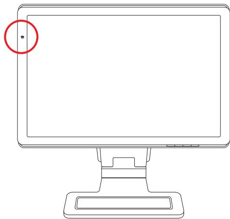
Ambient Light Sensor (Select Models Only)
An integrated light sensor, on the left front of the monitor, adjusts the LCD backlight output to the current ambient light conditions. By default, the ambient light sensor is on. You manually enable or disable the sensor using the Image Control main menu in the OSD. If you adjust the Quick View, Brightness, Contrast, or sRGB functions in the OSD, the light sensor will automatically be disabled.
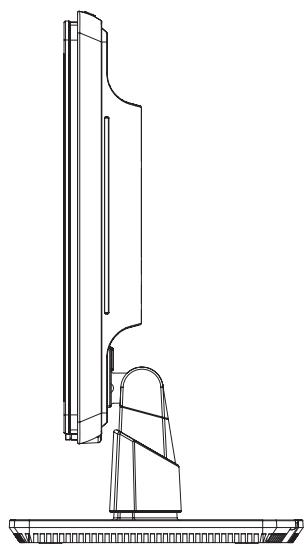
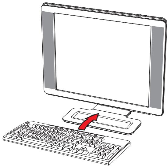
Keyboard Parking
If you need more space on your desktop, place the keyboard under the monitor (select models only) when not in use.
Operating the Monitor
CD Software and Utilities
The CD that is included with this monitor contains the drivers and software that you can install on your computer.
Installing Drivers
If you determine that you need to update the drivers, you can install the monitor-driver INF and ICM files from the CD (select models only), or download them from the Internet.
To install the monitor-driver software from the CD:
-
Insert the CD in your computer CD drive. The CD menu appears.
-
Select the language.
-
Click Install Monitor Driver Software.
-
Follow the onscreen instructions.
-
Restart the computer.
-
Ensure that the proper resolutions and refresh rates appear in the Display Control Panel settings. Refer to the Windows® operating system documentation for more information.
NOTE: You might need to install the digitally signed monitor drivers (INF or ICM files) manually from the CD, in case of an installation error. Refer to the "Driver Software Readme" file on the CD for instructions (in English only).

Downloading Updated Drivers from the Internet
To download the latest version of drivers and software files from the HP Support site:
- Refer to: http://www_hp.com/support
- Select your country/region.
- Select Download Drivers and Software.
- Enter the model number of your monitor. The software-download pages for your monitor are displayed.
- Download and install the driver and software files by using the instructions in the download pages.
- Ensure that your system meets the requirements.
Using the Auto-Adjustment Function
You can easily optimize the screen performance for the VGA input by using the Auto/Select button on the monitor and the auto-adjustment pattern software on the CD provided.
Do not use this procedure if your monitor is using a DVI or HDMI input (select models only). If your monitor is using the VGA input, this procedure can correct the following image-quality conditions:
Fuzzy or unclear focus
Ghosting, streaking, or shadowing effects
Faint vertical bars
Thin, horizontal scrolling lines
Off-center picture

CAUTION: Burn-in image damage may occur on monitors that display the same static image on screen for a prolonged period of time. *To avoid burn-in image damage on your monitor screen, you should always activate a screen saver application or turn off the monitor when it is not in use for a prolonged period of time. Image retention is a condition that may occur on all LCD screens.
- A prolonged period of time is 12 consecutive hours of non-use.
To use the auto-adjustment feature:
- Allow the monitor to warm up for 20 minutes before adjusting.
- Press the Auto/Select button on the monitor front panel.
You can also press the Menu button, and then select Image Control, followed by Auto Adjustment from the OSD menu. See "Adjusting Screen Quality" in this chapter.
If the result is not satisfactory, continue with the procedure.
-
Insert the CD in your computer CD drive. The CD menu displays.
-
Select the language.
- Select Open Auto-Adjustment Software.
- The setup test pattern displays.
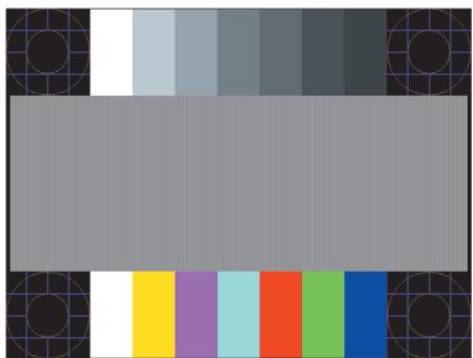
Auto-adjustment setup test pattern
- Press the Auto/Select button on the monitor front panel to produce a stable, centered image.
My Display Software
Use My Display (available for select models only) to choose preferences for optimum viewing. You can select settings for gaming, movies, photo editing or just working on documents and spreadsheets. My Display also provides an easy way to adjust settings such as brightness, color, and contrast.
To install the software:
- Insert the CD in your computer CD drive. The CD menu displays.
- Select the language.
- Click Install My Display Software (available on select models only).
- Follow the onscreen instructions.
- Restart the computer.
To open the My Display software:
- Click the HP My Display icon on the taskbar.

Or
- Click the Windows Vista start button on the taskbar.
- Click All Programs.
- Click HP My Display.
- Select HP My Display.
For additional information, refer to the onscreen Help within the software.
Front-Panel Controls
Control buttons are located on the front or top of the monitor:
| Icon | Description |
| Power | Turns the monitor on and to standby or sleep mode. |
| NOTE: The power button is located on the top or front of the monitor depending on the model. | |
| Menu | Opens, selects, or exits the OSD menu. |
| Adjusts the volume level. | |
| Opens the Quick View menu to quickly adjust settings for gaming, video, photo, and text. | |
| - | Navigates backward through the OSD menu and decreases adjustment levels. |
| + | Navigates forward through the OSD menu and increases adjustment levels. |
| Auto | Auto-adjusts the display to the ideal setting. |
| Select | Enters the selected option. |
Using the Onscreen Display (OSD)
An onscreen display is an image superimposed on a screen picture, commonly used by monitors, televisions, VCRs, and DVD players to display information such as volume, channel, and time.

NOTE: You can use My Display OSD software (select models only) or the front-panel control buttons to adjust settings.
- If the monitor is not already on, press the Power button to turn on the monitor.
- To access the OSD menu, press the Menu button. The OSD Main Menu displays.
- To navigate through the Main or Sub-Menu menu, press the + (Plus) button on the monitor's front panel to scroll up, or the - (Minus) button to scroll in reverse. Then press the Auto/Select button to select the highlighted function.
The menu moves to the top if you scroll down at the bottom of the selections. The menu moves to the bottom if you scroll up at the top of the selections.
- To adjust the scale of a selected item, press the + or - button.
- Select Save and Return.
If you don't want to save the setting, select Cancel from the Sub-Menu or Exit from the Main Menu.
- Press the Menu button to exit the OSD.

NOTE: When a menu is displayed, if the buttons are untouched for 30 seconds (factory default), adjustments and settings are saved and the menu closes.
OSD Menu Selections
The following table lists the On-Screen Display (OSD) menu selections and their functional descriptions. After changing an OSD menu item, and if the menu screen has these options, you may choose to:
- Cancel - to return to the previous menu level.
- Save and Return - to save all changes and return to the OSD Main Menu screen. This Save and Return option is active only if you change a menu item.
Reset to change back to the previous setting.
| Icon | Main Menu Options | Submenu Options | Description |
| → | Switch Video Input (select models only) | Switches the video input signal source when the monitor is connected to two active and valid video sources. Switching video input sources may take several seconds. | |
| Brightness | Adjusts the brightness level of the screen. | ||
| Contrast | Adjusts the contrast level of the screen. | ||
| Image Control | Adjusts the screen image. Also enables or disables the ambient light sensor (select models only). | ||
| Auto-Adjustment | Automatically adjusts the screen image (VGA Input only). | ||
| Horizontal Position | Adjusts the horizontal position of the picture (VGA Input only). | ||
| Vertical Position | Adjusts the vertical position of the picture (VGA Input only). | ||
| Custom Scaling (select models only) | Selects the method on how displayed information on the monitor will be formatted. Select: Fill to Screen — Image fills the entire screen and might look distorted or elongated because of non-proportional scaling of height and width. Fill to Aspect Ratio — Image is sized to fit the screen and maintains proportional image. | ||
| Sharpness (select models only) | On a scale of 1 to 5, adjusts the screen image to look sharper or softer. NOTE: If the one-to-one custom scaling menu is selected, scaling is disabled and the Sharpness feature is as well. | ||
| Ambient Light Sensor (select models only) | Adjusts the brightness of the screen depending on the ambient light of the environment. The sensor is on the left front of the monitor. By default the sensor is set to On. If you adjust the Quick View, Brightness, Contrast, or sRGB functions in the OSD, the ambient light sensor will automatically be disabled. | ||
| Clock | Minimizes any vertical bars or strips visible on the screen background. Adjusting the Clock will also change the horizontal screen image (VGA Input only). | ||
| Clock Phase | Adjusts the focus of the display. This adjustment allows you to remove any horizontal noise, and clear or sharpen the image of characters (VGA Input only). | ||
| Icon | Main Menu Options | Submenu Options | Description (Continued) |
| Color | 9300 K | Changes to slightly blueish white. | |
| 6500 K | Changes to slightly reddish white. | ||
| Custom Color | Selects and adjusts your own color scales: R - Sets your own red color levels. G - Sets your own green color levels. B - Sets your own blue color levels. | ||
| RGB | sRGB | Sets your screen colors to adapt to the color standards used in the image technology industry. | |
| Quick View | Video | Selects viewing mode. | |
| Photo | Selects the movie mode. | ||
| Gaming | Selects the photo mode. | ||
| Text | Selects the gaming mode. | ||
| Custom | Selects the text mode. | ||
| Language | Settings saved when user adjusts the Brightness, Contrast, or Color in one of the Quick View options. | ||
| Management | Volume | Selects the language in which the OSD menu is displayed. The factory default is English. | |
| OSD Control | Selects the power-management features of the monitor. | ||
| Power Saver | Enables the power saving feature (see "Power-Saver Feature" on page 8. Select: On Off The factory default is On. | ||
| Mode Display | Displays the resolution, refresh rate, and frequency information on the screen each time the OSD Main Menu is accessed. Select: On Off The factory default is On or Off, depending on the model. | ||
| Power-On Status Display | Displays the operating status of the monitor each time the monitor is powered on. Select the location to which to display the status:TopMiddleBottomOffThe factory default is Top or Off, depending on the model. | ||
| DDC/CI Support | Allows the computer to control some OSD menu features such as brightness, contrast, and color temperature. Set to:OnOffThe factory default is On. | ||
| Bezel Power LED(select models only) | Turns the light (LED) in the power button On and Off. When set to Off, the light will remain off at all times. | ||
| Sleep Timer | Provides the timer-adjustment menu options:Set Current Time — Sets the current time in hours and minutes.Set Sleep Time — Sets the time you want to place the monitor in sleep mode.Set on Time — Sets the time you want the monitor to wake up from sleep mode.Timer — Sets the Sleep Timer feature On or Off; the default setting is Off.Sleep Now — Immediately sets the monitor to enter sleep mode. | ||
| Default Video Input | Selects the default video input signal when the monitor is connected to two active and valid video sources. The default is DVI. You must restart the computer to have the change take effect. | ||
| Information | Selects and displays important information about the monitor. | ||
| Current Settings | Provides the current input video mode. | ||
| Recommended Settings | Provides the recommended resolution mode and refresh rate for the monitor. | ||
| Serial Number | Reports the serial number of the monitor. The serial number is needed if contacting HP technical support. | ||
| Version | Reports the firmware version of the monitor. | ||
| Backlight Hours | Reports the total hours of backlight operation. | ||
| Service Support | For service support, go to: http://www.hp.com/support | ||
| Factory Reset | Returns settings to factory defaults. | ||
Selecting Video Input Connectors
The input connectors are:
VGA connector (analog)
DVI-D connector (digital) for select models
HDMI connector for select models
The monitor automatically determines which inputs have valid video signals, and displays the image.
You can connect the VGA cable, the DVI-D cable, or both. If both cables are installed, the default input selection is DVI. The HDMI cable is in place of the DVI-D cable. The source of input can be switched using the Switch Video Input option in the OSD menu. Switching from a VGA to an HDMI input source may take several seconds.
Identifying Monitor Conditions
Special messages appear on the monitor screen for the following monitor conditions:
■ Input Signal Out of Range — Indicates the monitor does not support the video card's input signal because its resolution or refresh rate are set higher than the monitor supports.
Change your video card settings to a lower resolution or refresh rate. Restart your computer for the new settings to take effect.
■ Monitor Going to Sleep - Indicates the screen display is entering a sleep mode. The speakers are turned off in sleep mode.
Check Video Cable - Indicates a video input cable is not properly connected to the computer or monitor.
■ OSD Lock-out — The OSD can be enabled or disabled by pressing and holding the Menu button on the front panel for 10 seconds. If the OSD is locked, the warning message "OSD Lock-out" appears for 10 seconds.
If the OSD is locked, press and hold the Menu button for 10 seconds to unlock the OSD. If the OSD is unlocked, press and hold the Menu button for 10 seconds to lock the OSD.
■ No Input Signal — Indicates the monitor is not receiving a video signal from the computer on the monitor video input connector(s). Check to see if the computer or input signal source is off or in the power-saver mode.
■ Auto Adjustment in Progress — Indicates the auto-adjustment function is active. See "Adjusting Screen Quality" in this chapter.
Adjusting Screen Quality
The auto-adjustment feature automatically fine-tunes the image quality for display size, position, clock, and phase each time a new video mode is displayed. For more precise adjustments of VGA input, run the Auto-Adjustment software on the CD. See "Using the Auto-Adjustment Function" in this chapter.
If you want additional image-quality improvement, use the Clock and Clock Phase controls of the monitor to fine-tune the image. See "Optimizing Analog Video" in this chapter.
Optimizing Analog Video
This monitor contains advanced circuitry that allows the monitor to function as a standard analog monitor. Two controls in the OSD menu can be adjusted to improve analog image performance:
■ Clock - Increase or decrease the value to minimize any vertical bars or stripes visible on the screen background.
■ Clock Phase - Increase or decrease the value to minimize video distortion or video jitter.
Use these controls only when the auto-adjustment function does not provide a satisfactory monitor image in analog mode.
To obtain the best results:
- Allow the monitor to warm up for 20 minutes before adjusting.
- Display the adjustment-pattern application provided on the CD.
- Access the OSD menu, then select Image Control.
- Set the main Clock settings correctly first, because the Clock Phase settings depend on the main Clock setting. When adjusting the Clock and Clock Phase values, if the monitor images become distorted, continue adjusting the values until the distortion disappears.
To restore the factory settings, access the OSD menu, select Factory Reset, and then select Yes.
Power-Saver Feature
When the monitor is in normal operating mode, the Power light is aqua-white or green (depending on model) and the monitor uses the normal watts of power. For power usage, refer to "Technical Specifications" (Appendix B).
The monitor also supports a power-saver mode that is controlled by the computer. When the monitor is in the reduced-power state, the monitor screen is blank, the backlight is off, and the Power light is amber. The monitor uses minimum power. When the monitor is "awakened," a brief warm-up period occurs before the monitor returns to normal operating mode. The energy-saving reduced power state activates if the monitor does not detect either the horizontal sync signal or the vertical sync signal. The power-saver feature must be activated on your computer for this feature to work.
Refer to your computer documentation for instructions on setting energy-saver features (sometimes called power-management features).

NOTE: The energy-saver feature works only when the monitor is connected to computers that have energy-saver features.
High-Bandwidth Digital Content Protection (HDCP)
If your monitor supports HDCP, it can receive high-definition content. High-definition content is available in many sources, such as HD-DVD and Blu-Ray devices or HDTV air or cable broadcasts. If you do not have an HDCP-enabled monitor, you may see a black screen or a lower resolution picture when playing high-definition protected content. Your computer graphic card and monitor must both support HDCP to display protected content.
Preparing the Monitor for Shipping
Keep the original packing box in a storage area. You may need it later if you move or ship your monitor.
You may need to detach the monitor base when you ship the HP LCD monitor.
Removing the Monitor Base

WARNING: Do not remove the base from the pedestal while the monitor is standing in the upright position. Attempting to remove the base from the pedestal while the monitor is upright might injure the user.

WARNING: Before disassembling or folding the monitor, turn off the monitor power, and disconnect all power, video, and audio cables. To disconnect power from the equipment, unplug the power cord from the power outlet by grasping the power plug firmly. Never pull on the cord.

CAUTION: The screen is fragile. Placing the monitor screen down on a flat, soft area prevents scratches, defacing, or breakage. Avoid applying pressure to the LCD screen; doing so can cause damage.
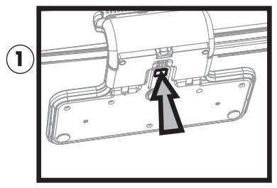
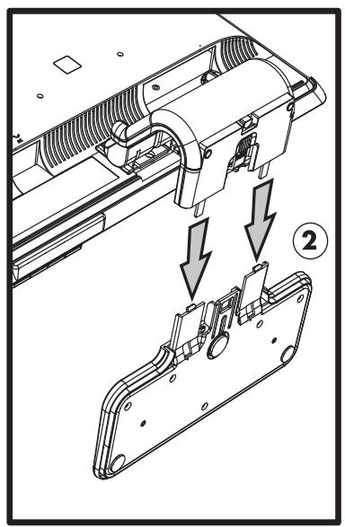
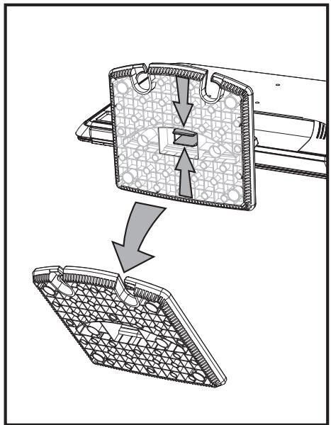
Removing the cantilever base
- Disconnect the power, video, and audio cables from the monitor.
- Set the monitor screen down on a flat, soft, protected surface.
- Press the center tab in (1) and detach the base from the monitor (2).
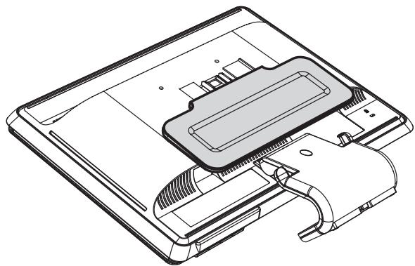
Removing the cantilever base
- Fold the monitor neck down, and place the monitor and base in the original packing box.
Removing the column base
- Disconnect the power, video, and audio cables from the monitor.
- Set the monitor screen down on a flat, soft, protected surface.
- Pinch and hold the tabs with one hand; then pull the base off with the other hand to detach the base from the monitor.
Removing the column base

WARNING: Be careful to avoid pinching or scraping your fingers when removing the base.
- Put the monitor and base in the original packing box.
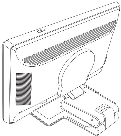
Folding the Double-Hinged Monitor
You don't have to remove this monitor base for shipping. Fold the double-hinged monitor in its original shipping position.

WARNING: Do not place the double-hinged monitor face down for folding. The base hinge can spring up and cause serious injury or damage.
- Turn the monitor to a horizontal position with no tilt.
- Lower the monitor all the way until the hinge is flat.
The monitor screen should still be vertical to the desktop so you can access the hinge.
- Place the shipping strap around the base, pull it tight, and connect it by sliding the strap ends through the slips.
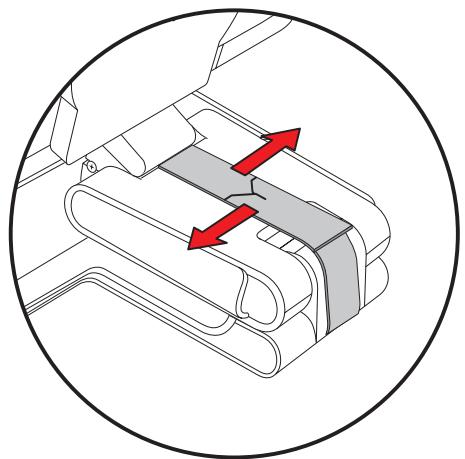
-
Lower the monitor screen down flat, horizontal to the desktop.
-
Pivot the monitor to the portrait position (in the figure, you would be facing the monitor where the straight arrow is).
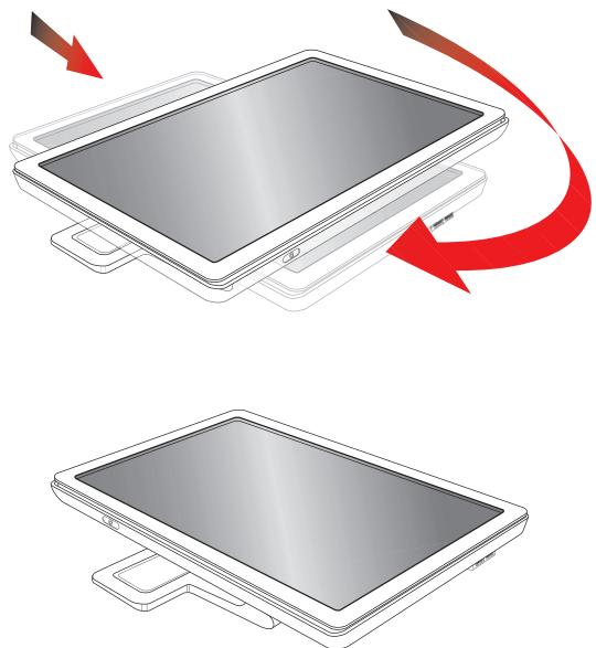
- Place the folded monitor, screen-side up, in its original shipping box.
Solving Common Problems
The following table lists possible problems, the possible cause of each problem, and the recommended solutions:
| Problem | Solution |
| Power LED is not on. | Make sure the Power button is on, and the power cord is properly connected to a grounded power outlet and to the monitor. Select Management in the OSD menu, and then select Bezel Power LED. Check if the Bezel Power LED option is set to Off and, if so, set to On mode. |
| Screen is blank. | Connect the power cord. Turn on the power. Connect the video cable properly. See “Setting Up the Monitor” for more information. Press a key on the keyboard or move the mouse to turn off the screen-blanking utility. |
| Screen is black or displaying at a lower resolution while displaying high-definition (HD) content. | Check if your monitor and computer support HDCP. Refer to “High-Bandwidth Digital Content Protection (HDCP)” or http://www.hp.com/support for more information. |
| Image appears blurred, indistinct, or too dark. | Press the Auto/Select button on the monitor front panel. If this does not correct the image, press the Menu button to open the OSD menu, and adjust the brightness and contrast scales as needed. |
| Image is not centered. | Press the Menu button to access the OSD menu. Select Image Control, and then select Horizontal Position or Vertical Position to adjust the horizontal or vertical position of the image. |
| “Check Video Cable” appears on screen. | Connect the monitor VGA signal cable to the VGA connector on the computer, or connect the DVI-D signal cable to the DVI connector on the computer. Be sure that the computer power is off while connecting the video cable. |
| “Input Signal Out of Range” appears on screen. | Restart your computer and enter Safe Mode. Change your settings to a supported setting (see the table in “Preset Video Modes” in Appendix B). Restart your computer, so that the new settings take effect. |
| Picture is fuzzy and has ghosting, shadowing problem. | Adjust the contrast and brightness controls. Make sure that you are not using an extension cable or switch box. We recommend plugging the monitor directly into the graphic card output connector on the back of your computer. For VGA input, the auto-adjustment feature might fix this problem. |
| Unable to set the monitor to the optimal resolution. | Make sure that the graphics card supports the optimal resolution. Make sure that the latest supported driver is installed for the graphics card. For HP and Compaq systems, you can download the latest graphics driver for your system from: http://www.hp.com/support For other systems, refer to the Web site for your graphics card. |
| Problem | Solution (Continued) |
| No Plug and Play. | In order for the Plug and Play feature of the monitor to work, you need a computer and graphic card that are compatible with Plug and Play. Check with your computer manufacturer. Check the monitor's video cable, and make sure that none of the pins are bent. Make sure that the HP monitor drivers are installed. Refer to "Installing Drivers" for more information. HP monitor drivers are also available at: http://www.hp.com/support |
| Picture bounces, flickers, or wave pattern is present in the picture. | Move electrical devices that may cause electrical interference as far away from the monitor as possible. Use the maximum refresh rate that your monitor is capable of at the resolution that you are using. |
| Monitor is always in "Sleep Mode (Amber LED)." | The computer power switch should be in the On position. The computer graphic card should be snugly seated in its slot. Check that the monitor video cable is properly connected to the computer. Inspect the monitor video cable, and make sure that none of the pins are bent. Check that your computer is operational: Press the Caps Lock key and observe the Caps Lock LED found on most keyboards. The LED should either turn on or off after hitting the Caps Lock key. |
| USB 2.0 ports are not working. | Make sure the USB hub cable is securely connected to the monitor and the computer. |
Getting Support from hp.com
Before you contact customer service, refer to HP Technical Support at: http://www.hp.com/support
Select your country/region, and then follow the links to the support page for your monitor.
Preparing to Call Technical Support
If you cannot solve a problem by using the troubleshooting tips in this section, you might have to call technical support. For technical support contact information, refer to the printed documentation included with the monitor. Have the following information available when you call:
Monitor model number (located on label on back of monitor)
Monitor serial number (located on label on back of monitor or in the OSD display in the Information menu)
Purchase date on invoice
Conditions under which the problem occurred
Error messages received
Hardware configuration
Name and version of hardware and software you are using
Locating the Rating Label
The rating label on the monitor provides the product number and serial number. You may need these numbers when contacting HP about your monitor model.
The rating label is on the back of the monitor.
Technical Specifications
All specifications represent the typical specifications provided by HP's component manufacturers; actual performance may vary either higher or lower.
HP LCD Monitors
Face treatment: Antiglare polarizer with hard coating (select models only)
Input Terminals:
VGA 15-pin D-type connector
DVI-D 24-pin D-type connector (select models only)
HDMI connector (select models only)
Specifications
model vp15
Display Type: TFT LCD active matrix
Screen Size: 15.0 in., 38.1 cm
Viewable Image Size: 15.0 in. diagonal, 38.1 cm diagonal
Tilt: -5^ to +25^
Maximum Weight (unpacked): 6.8 lb, 3.1 kg
Dimensions (including base) (h × w × d) : 13.9 × 15.9 × 7.68 in., 354 × 405 × 195 mm
Maximum Graphics Resolution: 1024 × 768 @ 75 Hz analog mode
Optimum Graphics Resolution: 1024 × 768 @ 60 Hz analog mode
Text Mode: 720 × 400
Dot Pitch: 0.297 × 0.297 ~mm
Horizontal Frequency (analog mode): 24 to 63kHz
Vertical Refresh Rate (analog mode): 50 to 76 Hz
Environmental Requirements
Temperature (independent of altitude)
Operating Temperature: 41^ to 95^ F, 5^ to 35^ C
Non-operating Temperature: -29^ to 140^, -20^ to 60^
Relative Humidity: 20% to 80%
Power Source: 100-240Vv, 50/60 Hz
Power Consumption: 31 watts maximum
Sleep Power Consumption: <2 watts typical
Specifications (Continued)
model vp17
| Display Type: | TFT LCD active matrix |
| Screen Size: | 17.0 in., 43.2 cm |
| Viewable Image Size: | 17.0 in., 43.2 cm diagonal |
| Tilt: | -5° to +25° |
| Maximum Weight (unpacked): | 11.7 lb, 5.3 kg |
| Dimensions (including base) (h x w x d): | 15.7 x 17.3 x 7.3 in., 398 x 440 x 184 mm |
| Maximum Graphics Resolution: | 1280 x 1024 @ 75 Hz analog mode |
| Optimum Graphics Resolution: | 1280 x 1024 @ 60 Hz analog mode |
| Text Mode: | 720 x 400 |
| Dot Pitch: | 0.264 x 0.264 mm |
| Horizontal Frequency (analog mode): | 24 to 83 kHz |
| Vertical Refresh Rate (analog mode): | 50 to 76 Hz |
| Environmental Requirements | |
| Temperature (independent of altitude) | |
| Operating Temperature: | 41° to 95° F, 5° to 35° C |
| Non-operating Temperature: | -29° to 140° F, -20° to 60° C |
| Relative Humidity: | 20% to 80% |
| Power Source: | 100–240V√, 50/60 Hz |
| Power Consumption: | 45 watts maximum |
| Sleep Power Consumption: | <2 watts typical |
model vp19
| Display Type: | TFT LCD active matrix |
| Screen Size: | 19.0 in., 48.3 cm |
| Viewable Image Size: | 19.0 in., 48.3 cm diagonal |
| Tilt: | -5° to +25° |
| Maximum Weight (unpacked): | 11.7 lb, 5.3 kg |
| Dimensions (including base) (h x w x d): | 16.8 x 19.1 x 7.3 in., 427 x 484 x 184 mm |
| Maximum Graphics Resolution: | 1280 x 1024 @ 75 Hz analog mode |
| Optimum Graphics Resolution: | 1280 x 1024 @ 60 Hz analog mode |
| Text Mode: | 720 x 400 |
| Dot Pitch: | 0.294 x 0.294 mm |
| Horizontal Frequency (analog mode): | 24 to 83 kHz |
| Vertical Refresh Rate (analog mode): | 50 to 76 Hz |
| Environmental Requirements | |
| Temperature (independent of altitude) | |
| Operating Temperature: | 41° to 95° F, 5° to 35° C |
| Non-operating Temperature: | -29° to 140° F, -20° to 60° C |
| Relative Humidity: | 20% to 80% |
| Power Source: | 100-240V√, 50/60 Hz |
| Power Consumption: | 47 watts maximum |
| Sleep Power Consumption: | <2 watts typical |
Specifications (Continued)
model FP1707
| Display Type: | TFT LCD active matrix |
| Screen Size: | 17.0 in., 43.2 cm |
| Viewable Image Size: | 17.0 in., 43.2 cm diagonal |
| Tilt: | -5° to +25° |
| Maximum Weight (unpacked): | 10.1 lb, 4.6 kg |
| Dimensions (including base) (h x w x d): | 15.4 x 17.4 x 8.2 in., 392 x 441 x 207 mm |
| Maximum Graphics Resolution: | 1280 x 1024 @ 75 Hz analog mode |
| Optimum Graphics Resolution: | 1280 x 1024 @ 60 Hz analog mode |
| Text Mode: | 720 x 400 |
| Dot Pitch: | 0.264 x 0.264 mm |
| Horizontal Frequency (analog mode): | 24 to 83 kHz |
| Vertical Refresh Rate (analog mode): | 50 to 76 Hz |
| Environmental Requirements | |
| Temperature (independent of altitude) | |
| Operating Temperature: | 41° to 95° F, 5° to 35° C |
| Non-operating Temperature: | -29° to 140° F, -20° to 60° C |
| Relative Humidity: | 20% to 80% |
| Power Source: | 100–240V√, 50/60 Hz |
| Power Consumption: | 45 watts maximum |
| Sleep Power Consumption: | <2 watts typical |
model WF1907
| Display Type: | TFT LCD active matrix |
| Screen Size: | 19.0 in., 48.3 cm |
| Viewable Image Size: | 19.0 in., 48.3 cm diagonal |
| Tilt: | -5° to +25° |
| Maximum Weight (unpacked): | 10.8 lb, 4.9 kg |
| Dimensions (including base) (h x w x d): | 14.7 x 20.1 x 8.2 in., 374 x 511 x 207 mm |
| Maximum Graphics Resolution: | 1440 x 900 @ 60 Hz analog mode |
| Optimum Graphics Resolution: | 1440 x 900 @ 60 Hz analog mode |
| Text Mode: | 720 x 400 |
| Dot Pitch: | 0.294 x 0.294 mm |
| Horizontal Frequency (analog mode): | 24 to 83 kHz |
| Vertical Refresh Rate (analog mode): | 50 to 76 Hz |
| Environmental Requirements | |
| Temperature (independent of altitude) | |
| Operating Temperature: | 41° to 95° F, 5° to 35° C |
| Non-operating Temperature: | -29° to 140° F, -20° to 60° C |
| Relative Humidity: | 20% to 80% |
| Power Source: | 100–240V√, 50/60 Hz |
| Power Consumption: | 49 watts maximum |
| Sleep Power Consumption: | <2 watts typical |
Specifications (Continued)
model w1707
| Display Type: | TFT LCD active matrix |
| Screen Size: | 17.0 in., 43.2 cm |
| Viewable Image Size: | 17.0 in., 43.2 cm diagonal |
| Tilt: | -5° to +25° |
| Maximum Weight (unpacked): | 8.4 lb, 3.8 kg |
| Dimensions (including base) (h x w x d): | 14.3 x 16.3 x 17.2 in., 362 x 414 x 184 mm |
| Maximum Graphics Resolution: | 1440 x 900 @ 60 Hz analog mode |
| Optimum Graphics Resolution: | 1440 x 900 @ 60 Hz analog mode |
| Text Mode: | 720 x 400 |
| Dot Pitch: | 0.283 x 0.284 mm |
| Horizontal Frequency (analog mode): | 24 to 83 kHz |
| Vertical Refresh Rate (analog mode): | 50 to 76 Hz |
| Environmental Requirements | |
| Temperature (independent of altitude) | |
| Operating Temperature: | 41° to 95° F, 5° to 35° C |
| Non-operating Temperature: | -29° to 140° F, -20° to 60° C |
| Relative Humidity: | 20% to 80% |
| Power Source: | 100–240V√, 50/60 Hz |
| Power Consumption: | 49 watts maximum |
| Sleep Power Consumption: | <2 watts typical |
model w1907
| Display Type: | TFT LCD active matrix |
| Screen Size: | 19.0 in., 48.3 cm |
| Viewable Image Size: | 19.0 in., 48.3 cm diagonal |
| Tilt: | -5° to +25° |
| Maximum Weight (unpacked): | 11.0 lb, 5.0 kg |
| Dimensions (including base) (h x w x d): | 14.9 x 17.9 x 7.3 in., 380 x 454 x 185 mm |
| Maximum Graphics Resolution: | 1440 x 900 @ 60 Hz analog mode |
| Optimum Graphics Resolution: | 1440 x 900 @ 60 Hz analog mode |
| Text Mode: | 720 x 400 |
| Dot Pitch: | 0.283 x 0.284 mm |
| Horizontal Frequency (analog mode): | 24 to 83 kHz |
| Vertical Refresh Rate (analog mode): | 50 to 76 Hz |
| Environmental Requirements | |
| Temperature (independent of altitude) | |
| Operating Temperature: | 41° to 95° F, 5° to 35° C |
| Non-operating Temperature: | -29° to 140° F, -20° to 60° C |
| Relative Humidity: | 20% to 80% |
| Power Source: | 100–240V√, 50/60 Hz |
| Power Consumption: | 49 watts maximum |
| Sleep Power Consumption: | <2 watts typical |
Specifications (Continued)
model w2007
| Display Type: | TFT LCD active matrix |
| Screen Size: | 20.0 in., 50.8 cm |
| Viewable Image Size: | 20.0 in., 50.8 cm diagonal |
| Tilt: | -5° to +25° |
| Maximum Weight (unpacked): | 13.3 lb, 6.0 kg |
| Dimensions (including base) (h x w x d): | 15.6 x 19.3 x 7.3 in., 397 x 490 x 184 mm |
| Maximum Graphics Resolution: | 1680 x 1050 @ 60 Hz analog mode |
| Optimum Graphics Resolution: | 1680 x 1050 @ 60 Hz analog mode |
| Text Mode: | 720 x 400 |
| Dot Pitch: | 0.282 x 0.282 mm |
| Horizontal Frequency (analog mode): | 24 to 83 kHz |
| Vertical Refresh Rate (analog mode): | 55 to 76 Hz |
| Environmental Requirements | |
| Temperature (independent of altitude) | |
| Operating Temperature: | 41° to 95° F, 5° to 35° C |
| Non-operating Temperature: | -29° to 140° F, -20° to 60° C |
| Relative Humidity: | 20% to 80% |
| Power Source: | 100-240V√, 50/60 Hz |
| Power Consumption: | 52 watts maximum |
| Sleep Power Consumption: | <2 watts typical |
model w2207
| Display Type: | TFT LCD active matrix |
| Screen Size: | 22.0 in., 55.9 cm |
| Viewable Image Size: | 22.0 in., 55.9 cm diagonal |
| Tilt: | -5° to +25° |
| Maximum Weight (unpacked): | 19.8 lb, 9.0 kg |
| Dimensions (h x w x d) | |
| (high position): | 18.9 x 20.6 x 11.4 in., 481 x 523 x 289 mm |
| (low position): | 14.6 x 20.6 x 11.4 in., 371 x 523 x 289 mm |
| Maximum Graphics Resolution: | 1680 x 1050 @ 60 Hz analog mode |
| Optimum Graphics Resolution: | 1680 x 1050 @ 60 Hz analog mode |
| Text Mode: | 720 x 400 |
| Dot Pitch: | 0.282 x 0.282 mm |
| Horizontal Frequency (analog mode): | 24 to 83 kHz |
| Vertical Refresh Rate (analog mode): | 50 to 76 Hz |
| Environmental Requirements | |
| Temperature (independent of altitude) | |
| Operating Temperature: | 41° to 95°F, 5° to 35°C |
| Non-operating Temperature: | -29° to 140°F, -20° to 60°C |
| Relative Humidity: | 20% to 80% |
| Power Source: | 100-240Vv, 50/60 Hz |
| Power Consumption: | 65 watts maximum |
| Sleep Power Consumption: | <2 watts typical |
Specifications (Continued)
model w2216
| Display Type: | TFT LCD active matrix |
| Screen Size: | 21.6 in., 54.9 cm |
| Viewable Image Size: | 21.6 in., 54.9 cm diagonal |
| Tilt: | -5° to +25° |
| Maximum Weight (unpacked): | 19.6 lb, 8.9 kg |
| Dimensions (h x w x d): | 18.9 x 20.6 x 11.4 in., 481 x 523 x 289 mm |
| Maximum Graphics Resolution: | 1680 x 1050 @ 60 Hz analog mode |
| Optimum Graphics Resolution: | 1680 x 1050 @ 60 Hz analog mode |
| Text Mode: | 720 x 400 |
| Dot Pitch: | 0.282 x 0.282 mm |
| Horizontal Frequency (analog mode): | 24 to 83 kHz |
| Vertical Refresh Rate (analog mode): | 50 to 76 Hz |
| Environmental Requirements | |
| Temperature (independent of altitude) | |
| Operating Temperature: | 41° to 95° F, 5° to 35° C |
| Non-operating Temperature: | -29° to 140° F, -20° to 60° C |
| Relative Humidity: | 25% to 85% |
| Power Source: | 100–240V√, 50/60 Hz |
| Power Consumption: | 65 watts maximum |
| Sleep Power Consumption: | <2 watts typical |
model w2408
| Display Type: | TFT LCD active matrix |
| Screen Size: | 24.0 in., 61.0 cm |
| Viewable Image Size: | 24.0 in., 61.0 cm diagonal |
| Tilt: | -5° to +25° |
| Maximum Weight (unpacked): | 21.6 lb, 9.8 kg |
| Dimensions (h x w x d) | |
| (high position): | 19.7 x 23.1 x 11.4 in., 500 x 586 x 289 mm |
| (low position): | 16.3 x 23.1 x 11.4 in., 415 x 586 x 289 mm |
| Maximum Graphics Resolution: | 1920 x 1200 @ 60 Hz analog mode |
| Optimum Graphics Resolution: | 1920 x 1200 @ 60 Hz analog mode |
| Text Mode: | 720 x 400 |
| Dot Pitch: | 0.282 x 0.282 mm |
| Horizontal Frequency (analog mode): | 24 to 94 kHz |
| Vertical Refresh Rate (analog mode): | 48 to 85 Hz |
| Environmental Requirements | |
| Temperature (independent of altitude) | |
| Operating Temperature: | 41° to 95°F, 5° to 35°C |
| Non-operating Temperature | -29° to 140°F, -20° to 60°C |
| Relative Humidity: | 20% to 80% |
| Power Source: | 100–240V, 50/60 Hz |
| Power Consumption: | 130 watts maximum |
| Sleep Power Consumption: | <2 watts typical |
Preset Video Modes
The monitor automatically recognizes many preset video input modes that will appear properly sized and centered on the screen. The following modes are assigned at the factory and are the most commonly used display resolutions:
vp15 supports preset modes 1 through 11
vp17, vp19, and FP1707 support preset modes 1 through 15
| Factory Preset Video Input Modes, vp15, vp17, vp19, and FP1707 | |||
| Preset | Resolution | Horizontal Frequency (kHz) | Vertical Frequency (Hz) |
| 1 | 640 x 480 | 31.4 | 59.9 |
| 2 | 640 x 480 | 37.8 | 72.8 |
| 3 | 640 x 480 | 37.5 | 75.0 |
| 4 | 720 x 400 | 31.4 | 70.0 |
| 5 | 800 x 600 | 37.8 | 60.3 |
| 6 | 800 x 600 | 48.0 | 72.1 |
| 7 | 800 x 600 | 46.8 | 75.0 |
| 8 | 832 x 624 | 49.7 | 74.5 |
| 9 | 1024 x 768 | 48.3 | 60.0 |
| 10 | 1024 x 768 | 56.4 | 70.0 |
| 11 | 1024 x 768 | 60.0 | 75.0 |
| 12 | 1152 x 870 | 68.6 | 75.0 |
| 13 | 1152 x 900 | 71.7 | 76.1 |
| 14 | 1280 x 1024 | 63.9 | 60.2 |
| 15 | 1280 x 1024 | 79.9 | 75.0 |
■ w1707 supports preset modes 1 through 15
| Factory Preset Video Input Modes, w1707 | |||
| Preset | Resolution | Horizontal Frequency (kHz) | Vertical Frequency (Hz) |
| 1 | 640 x 480 | 31.4 | 59.9 |
| 2 | 640 x 480 | 37.8 | 72.8 |
| 3 | 720 x 400 | 31.4 | 70.0 |
| 4 | 800 x 600 | 37.8 | 60.3 |
| 5 | 800 x 600 | 46.8 | 75.0 |
| 6 | 832 x 624 | 49.7 | 74.5 |
| 7 | 1024 x 768 | 48.3 | 60.0 |
| 8 | 1024 x 768 | 60.0 | 75.0 |
| 9 | 1152 x 870 | 68.6 | 75.0 |
| 10 | 1152 x 900 | 61.8 | 65.9 |
| Preset | Resolution | Horizontal Frequency (kHz) | Vertical Frequency (Hz) |
| 11 | 1280 x 768 | 47.4 | 60.0 |
| 12 | 1280 x 960 | 60.0 | 60.0 |
| 13 | 1280 x 1024 | 64.3 | 60.0 |
| 14 | 1280 x 1024 | 79.9 | 75.0 |
| 15 | 1440 x 900 | 55.9 | 59.8 |
■ WF1907 and w1907 support preset modes 1 through 16
Factory Preset Video Input Modes, WF1907 and w1907
| Preset | Resolution | Horizontal Frequency (kHz) | Vertical Frequency (Hz) |
| 1 | 640 x 480 | 31.5 | 59.9 |
| 2 | 640 x 480 | 37.5 | 75.0 |
| 3 | 720 x 400 | 31.5 | 70.0 |
| 4 | 800 x 600 | 37.9 | 60.3 |
| 5 | 800 x 600 | 46.9 | 75.0 |
| 6 | 832 x 624 | 49.7 | 74.5 |
| 7 | 1024 x 768 | 48.4 | 60.0 |
| 8 | 1024 x 768 | 60.0 | 75.0 |
| 9 | 1152 x 720 | 44.9 | 60.0 |
| 10 | 1152 x 870 | 68.7 | 75.1 |
| 11 | 1152 x 900 | 61.8 | 65.9 |
| 12 | 1280 x 768 | 47.4 | 60.0 |
| 13 | 1280 x 960 | 60.0 | 60.0 |
| 14 | 1280 x 1024 | 63.9 | 60.0 |
| 15 | 1280 x 1024 | 79.9 | 75.0 |
| 16 | 1440 x 900 | 55.9 | 59.9 |
w2007 supports preset modes 1 through 18
| Factory Preset Video Input Modes, w2007 | |||
| Preset | Resolution | Horizontal Frequency (kHz) | Vertical Frequency (Hz) |
| 1 | 640 x 480 | 31.4 | 59.9 |
| 2 | 640 x 480 | 37.5 | 75.0 |
| 3 | 720 x 400 | 31.5 | 70.0 |
| 4 | 800 x 600 | 37.9 | 60.3 |
| 5 | 800 x 600 | 46.8 | 75.0 |
| 6 | 832 x 624 | 49.7 | 74.5 |
| 7 | 1024 x 768 | 48.3 | 60.0 |
| 8 | 1024 x 768 | 60.0 | 75.0 |
| 9 | 1024 x 768 | 68.6 | 85.0 |
| 10 | 1152 x 720 | 44.8 | 60.0 |
| 11 | 1152 x 870 | 68.7 | 75.0 |
| 12 | 1152 x 900 | 61.8 | 65.9 |
| 13 | 1280 x 768 | 47.4 | 76.1 |
| 14 | 1280 x 960 | 60.0 | 60.0 |
| 15 | 1280 x 1024 | 63.9 | 60.0 |
| 16 | 1280 x 1024 | 79.9 | 75.0 |
| 17 | 1440 x 900 | 59.9 | 59.9 |
| 18 | 1680 x 1050 | 65.2 | 60.0 |
■ w2207 supports preset modes 1 through 18
| Factory Preset Video Input Modes, w2207 | |||
| Preset | Resolution | Horizontal Frequency (kHz) | Vertical Frequency (Hz) |
| 1 | 640 x 480 | 31.4 | 59.9 |
| 2 | 640 x 480 | 37.5 | 75.0 |
| 3 | 720 x 400 | 31.5 | 70.0 |
| 4 | 800 x 600 | 37.9 | 60.3 |
| 5 | 800 x 600 | 46.9 | 75.0 |
| 6 | 832 x 624 | 49.7 | 74.5 |
| 7 | 1024 x 768 | 48.4 | 60.0 |
| 8 | 1024 x 768 | 60.0 | 75.0 |
| 9 | 1152 x 720 | 44.8 | 60.0 |
| 10 | 1152 x 870 | 68.7 | 75.1 |
| 11 | 1152 x 900 | 61.8 | 65.9 |
| Preset | Resolution | Horizontal Frequency (kHz) | Vertical Frequency (Hz) |
| 12 | 1280 x 768 | 47.4 | 60.0 |
| 13 | 1280 x 960 | 60.0 | 60.0 |
| 14 | 1280 x 1024 | 63.9 | 60.0 |
| 15 | 1280 x 1024 | 79.9 | 75.0 |
| 16 | 1440 x 900 | 55.9 | 59.9 |
| 17 | 1600 x 1000 | 61.6 | 60.0 |
| 18 | 1680 x 1050 | 65.3 | 60.0 |
■ w2216 supports preset modes 1 through 18
| Factory Preset Video Input Modes, w2216 | |||
| Preset | Resolution | Horizontal Frequency (kHz) | Vertical Frequency (Hz) |
| 1 | 640 x 480 | 31.4 | 59.9 |
| 2 | 640 x 480 | 37.5 | 75.0 |
| 3 | 720 x 400 | 31.5 | 70.0 |
| 4 | 800 x 600 | 37.9 | 60.3 |
| 5 | 800 x 600 | 46.9 | 75.0 |
| 6 | 832 x 624 | 49.7 | 74.5 |
| 7 | 1024 x 768 | 48.4 | 60.0 |
| 8 | 1024 x 768 | 60.0 | 75.0 |
| 9 | 1152 x 720 | 44.8 | 60.0 |
| 10 | 1152 x 870 | 68.7 | 75.1 |
| 11 | 1152 x 900 | 61.8 | 65.9 |
| 12 | 1280 x 768 | 47.4 | 60.0 |
| 13 | 1280 x 960 | 60.0 | 60.0 |
| 14 | 1280 x 1024 | 63.9 | 60.0 |
| 15 | 1280 x 1024 | 79.9 | 75.0 |
| 16 | 1440 x 900 | 55.9 | 59.9 |
| 17 | 1600 x 1000 | 61.6 | 60.0 |
| 18 | 1680 x 1050 | 65.3 | 60.0 |
■ w2408 supports preset modes 1 through 20
| Factory Preset Video Input Modes, w2408 | |||
| Preset | Resolution | Horizontal Frequency (kHz) | Vertical Frequency (Hz) |
| 1 | 640 x 480 | 31.5 | 59.9 |
| 2 | 640 x 480 | 37.5 | 75.0 |
| 3 | 720 x 400 | 31.5 | 70.0 |
| 4 | 800 x 600 | 37.9 | 60.3 |
| 5 | 800 x 600 | 46.9 | 75.0 |
| 6 | 832 x 624 | 49.7 | 74.5 |
| 7 | 1024 x 768 | 48.4 | 60.0 |
| 8 | 1024 x 768 | 60.0 | 75.0 |
| 9 | 1152 x 720 | 44.8 | 60.0 |
| 10 | 1152 x 870 | 68.7 | 75.1 |
| 11 | 1280 x 768 | 47.4 | 60.0 |
| 12 | 1280 x 960 | 60.0 | 60.0 |
| 13 | 1280 x 1024 | 63.9 | 60.0 |
| 14 | 1280 x 1024 | 79.9 | 75.0 |
| 15 | 1440 x 900 | 55.9 | 59.9 |
| 16 | 1600 x 1000 | 61.6 | 60.0 |
| 17 | 1680 x 1050 | 65.3 | 60.0 |
| 18 | 1600 x 1200 | 75.0 | 60.0 |
| 19 | 1600 x 1200 | 93.8 | 75.0 |
| 20 | 1920 x 1200 | 74.0 | 60.0 |
LCD Monitor Quality and Pixel Policy
The HP LCD Monitor uses high-precision technology, manufactured according to high standards, to help guarantee trouble-free performance. Nevertheless, the display may have cosmetic imperfections that appear as small bright or dark spots. This is common to all LCD displays used in products supplied by all vendors and is not specific to the HP LCD Monitor. These imperfections are caused by one or more defective pixels or subpixels.
A pixel consists of one red, one green, and one blue subpixel.
A defective whole pixel is always turned on (a bright spot on a dark background), or it is always off (a dark spot on a bright background). The first is the more visible of the two.
A defective subpixel (dot defect) is less visible than a defective whole pixel, and is small and only visible on a specific background.
To locate defective pixels, the monitor should be viewed under normal operating conditions and in normal operating mode at a supported resolution and refresh rate, from a distance of approximately 50~cm (16 inches).
We expect that, over time, the industry will continue to improve its ability to produce displays with fewer cosmetic imperfections, and we will adjust guidelines as improvements are made.
For more information about your HP LCD Monitor, refer to the HP Web site at: http://www.hp.com/support
Power Cord Set Requirements
The monitor power supply is provided with Automatic Line Switching (ALS). This feature allows the monitor to operate on input voltages between 100-240V, 50/60 Hz, 1.5A.
The power cord set (flexible cord or wall plug) received with the monitor meets the requirements for use in the country/region where you purchased the equipment.
If you need to obtain a power cord for a different country/region, you should purchase a power cord that is approved for use in that country/region.
The power cord must be rated for the product and for the voltage and current marked on the product's electrical ratings label. The voltage and current rating of the cord should be greater than the voltage and current rating marked on the product. In addition, the cross-sectional area of the wire must be a minimum of 0.75mm^2 or 18AWG, and the length of the cord must be between 4.94 ft. (1.5 m) and 12 ft. (3.6 m). If you have questions about the type of power cord to use, contact your HP-authorized service provider.
A power cord should be routed so that it is not likely to be walked on or pinched by items placed upon it or against it. Particular attention should be paid to the plug, electrical outlet, and the point where the cord exits from the product.
Agency Regulatory Notices
Federal Communications Commission Notice
This equipment has been tested and found to comply with the limits for a Class B digital device, pursuant to Part 15 of the FCC Rules. These limits are designed to provide reasonable protection against harmful interference in a residential installation. This equipment generates, uses, and can radiate radio frequency energy and, if not installed and used in accordance with the instructions, may cause harmful interference to radio communications. However, there is no guarantee that interference will not occur in a particular installation. If this equipment does cause harmful interference to radio or television reception, which can be determined by turning the equipment off and on, the user is encouraged to try to correct the interference by one or more of the following measures:
Reorient or relocate the receiving antenna.
Increase the separation between the equipment and the receiver.
Connect the equipment into an outlet on a circuit different from that to which the receiver is connected.
■ Consult the dealer or an experienced radio or television technician for help.
Modifications
The FCC requires the user to be notified that any changes or modifications made to this device that are not expressly approved by Hewlett-Packard Company may void the user's authority to operate the equipment.
Cables
Connections to this device must be made with shielded cables with metallic RFI/EMI connector hoods to maintain compliance with FCC rules and regulations.
Declaration of Conformity for Products Marked with FCC Logo, United States Only
This device complies with Part 15 of the FCC Rules. Operation is subject to the following two conditions: (1) this device may not cause harmful interference, and (2) this device must accept any interference received, including interference that may cause undesired operation.
For questions regarding your product, contact:
Hewlett-Packard Company
P. O. Box 692000, Mail Stop 530113
Houston, Texas 77269-2000
Or
Call: 1-800-474-6836
For questions regarding this FCC declaration, contact:
Hewlett-Packard Company
P. O. Box 692000, Mail Stop 510101
Houston, Texas 77269-2000
Or
Call: 1-281-514-3333
To identify this product, refer to the part, series, or model number found on the product.
Materials Disposal
This HP product contains mercury in the fluorescent lamp in the display LCD that might require special handling at end-of-life:
Disposal of this material can be regulated because of environmental considerations. For disposal or recycling information, contact your local authorities or the Electronic Industries Alliance (EIA) (http://www.eiae.org).
Canadian Notice
This Class B digital apparatus meets all requirements of the Canadian Interference-Causing Equipment Regulations.
Avis Canadien
European Union Regulatory Notice
This product complies with the following EU Directives:
Low Voltage Directive 2006/95/EC
EMC Directive 2004/108/EC
Compliance with these directives implies conformity to applicable harmonized European standards (European Norms) which are listed on the EU Declaration of Conformity issued by Hewlett-Packard for this product or product family.
This compliance is indicated by one of the following conformity markings placed on the product:

This marking is valid for non-Telecom products and for EU harmonized Telecom products (for example, Bluetooth).

XXXX*
This marking is valid for EU non-harmonized Telecom products.
*Notified body number (used only if applicable--refer to the product label).

Hewlett-Packard GmbH, HQ-TRE, Herrenberger Straße 140, 71034 Böblingen, Germany
Disposal of Waste Equipment by Users in Private Households in the European Union


This symbol on the product or on its packaging indicates that this product must not be disposed of with your other household waste. Instead, it is your responsibility to dispose of your waste equipment by handing it over to a designated collection point for the recycling of waste electrical and electronic equipment. The separate collection and recycling of your waste equipment at the time of disposal will help to conserve natural resources and ensure that it is recycled in a manner that protects human health and the environment. For more information about where you can drop off your waste equipment for recycling, please contact your local city office, your household waste disposal service or the shop where you purchased the product.
Japanese Notice
Japanese Power Cord Notice
Japanese Material Content Declaration
A Japanese regulatory requirement, defined by Specification JIS-C-0950, 2005, mandates that manufacturers provide Material Content Declarations for certain categories of electronic products offered for sale after July 1, 2006. To view the JIS-C-0950 material declaration for this product, visit www.hp.com/go/jisc0950.
Products marked with the ENERGY STAR® logo on the packaging box qualify with the U.S. Environmental Protection Agency's ENERGY STAR® guidelines for energy efficiency.
Products with the ENERGY STAR® label are designed to use less energy, help you save money on utility bills, and help protect the environment.
ENERGY STAR® is a registered trademark owned by the U.S. government.

HP Recycling Program
HP offers product end-of-life return programs for HP and other manufacturers' hardware in several geographic areas. The terms and availability of these programs vary by geography because of differences in regulatory requirements and local customer demand. For information on the HP recycling program, refer to the HP Web site at: http://www.hp.com/recycle
The Table of Toxic and Hazardous Substances/Elements and their Content
as required by China's
Management Methods for Controlling Pollution by Electronic Information Products
| Part Name | Toxic and Hazardous Substances and Elements | |||||
| Lead (Pb) | Mercury (Hg) | Cadmium (Cd) | Hexavalent Chromium (Cr(VI)) | Polybrominated biphenyls (PBB) | Polybrominated diphenyl ethers (PBDE) | |
| Liquid Crystal Display Panel | X | X | O | O | O | O |
| Chassis/Other | X | O | O | O | O | O |
O: Indicates that this toxic or hazardous substance contained in all of the homogeneous materials for this part is below the limit requirement in SJ/T11363-2006.
X: Indicates that this toxic or hazardous substance contained in at least one of the homogeneous materials used for this part is above the limit requirement in SJ/T11363-2006.
All parts named in this table with an "X" are in compliance with the European Union's RoHS Legislation – "Directive 2002/95/EC of the European Parliament and of the Council of 27 January 2003 on the restriction of the use of certain hazardous substances in electrical and electronic equipment".
Note: The referenced Environmental Protection Use Period Marking was determined according to normal operating use conditions of the product such as temperature and humidity.
产品中有毒有害物质或元素的名称及含量

- Notational Conventions
- Notes, Cautions, andWarnings
- Product Features
- Safety and Maintenance Guidelines
- Setting Up the Monitor
- Operating the Monitor
- Preparing the Monitor for Shipping
- A Troubleshooting
- B Technical Specifications
- C Agency Regulatory Notices
- HP LCD Monitors
- Features
- Base Designs
- Safety and Maintenance Guidelines
- Important Safety Information
- Safety Precautions
- Maintenance Guidelines
- Cleaning the Monitor
- Setting Up the Monitor
- Unpacking the Monitor
- Installing the Monitor
- Installing on a Desktop
- Unfolding the double-inged monitor
- Assembling the cantilever base
- Assembling the column base
- Wall-Mounting the Monitor (Mounting Fixture not Supplied)
- Preparing the double-hinged monitor for wall-mounting
- Preparing the cantilever-base monitor for wall-mounting
- Preparing the column-base monitor for wall-mounting
- Reinstalling the desktop pedestal and base for the monitor
- Connecting the VGA (Analog) or DVI-D (Digital) Cable
- To connect the VGA cable
- To connect the DVI-D cable
- Connecting the HDMI Cable
- Audio and Video Cables and Adapters
- Connecting the Audio Cable
- Connecting the USB Hub Cable
- Connecting USB Devices to the Monitor
- Connecting the Power Cable
- Cable Management
- Adjusting the Tilt
- Adjusting the Swivel (Select Models Only)
- Adjusting the Height (Select Models Only)
- Pivoting the Monitor (Select Models Only)
- Ambient Light Sensor (Select Models Only)
- Keyboard Parking
- Operating the Monitor
- CD Software and Utilities
- Installing Drivers
- Downloading Updated Drivers from the Internet
- Using the Auto-Adjustment Function
- My Display Software
- Front-Panel Controls
- Using the Onscreen Display (OSD)
- OSD Menu Selections
- Selecting Video Input Connectors
- Identifying Monitor Conditions
- Adjusting Screen Quality
- Optimizing Analog Video
- Power-Saver Feature
- High-Bandwidth Digital Content Protection (HDCP)
- Preparing the Monitor for Shipping
- Removing the Monitor Base
- Removing the cantilever base
- Removing the column base
- Folding the Double-Hinged Monitor
- Solving Common Problems
- Getting Support from hp.com
- Preparing to Call Technical Support
- Locating the Rating Label
- Technical Specifications
- Specifications
- model vp15
- Specifications (Continued)
- model vp17
- model vp19
- model FP1707
- model WF1907
- model w1707
- model w1907
- model w2007
- model w2207
- model w2216
- model w2408
- Preset Video Modes
- LCD Monitor Quality and Pixel Policy
- Power Cord Set Requirements
- Agency Regulatory Notices
- Federal Communications Commission Notice
- Modifications
- Cables
- Declaration of Conformity for Products Marked with FCC Logo, United States Only
- Materials Disposal
- Canadian Notice
- Avis Canadien
- European Union Regulatory Notice
- Disposal of Waste Equipment by Users in Private Households in the European Union
- Japanese Notice
- Japanese Power Cord Notice
- Japanese Material Content Declaration
- HP Recycling Program
- The Table of Toxic and Hazardous Substances/Elements and their Content
Brand : COMPAQ
Model : W2408
Category : Monitor