
Fixed Points - HILTI - Free user manual and instructions
Find the device manual for free Fixed Points HILTI in PDF.


| Type | Fixed point / anchor system for pipe installation |
| Brand | HILTI |
| Model range | Fixed Points (MFP-CSL, MFP-L, MFP-UL, MFP-UM, MFP-UHD, etc.) |
| Application | Controlling thermal expansion and anchoring pipes in heating systems |
| Material | Galvanized steel components; EPDM sound insulation on -I variants |
| Dimensions | Pipe diameters from 21 to 326 mm; height up to 2000 mm |
| Weight | Varies by configuration; approx. 2–15 kg per set |
| Power supply | None (mechanical system) |
| Max load capacity | Up to 44 kN depending on model and anchoring |
| Pipe ring compatibility | MFP-PC series with M20 thread, sizes 21-22 to 318-326 |
| Brace principle | M16 threaded rods, tension-only load transfer |
| Sound insulation | EPDM on insulated models; max long-term exposure 120°C |
| Fire resistance | Up to F120 for selected heavy-duty models |
| Temperature range | Non-insulated up to 600°C with reduction factors |
| Installation | Concrete anchors (HUS3-H/HST3) or MI/MIQ connectors |
| Maintenance | Periodic visual inspection for corrosion, damage, and tightness |
| Safety | Ensure load direction matches threaded rod tension; lateral loads require individual evaluation |
| Spare parts | Threaded rods, bracing sets, base plate adapters, pipe rings available separately |
| Standards | Eurocode 3; fire design per EAD 280016-00-0602 / EN 1363 |
| Repairability | Fully repairable by replacing individual components |
| Documentation | Installation Technical Manual, v1.2, 08.2019, 110 pages |
Frequently Asked Questions - Fixed Points HILTI
User questions about Fixed Points HILTI
0 question about this device. Answer the ones you know or ask your own.
Ask a new question about this device
Download the instructions for your in PDF format for free! Find your manual Fixed Points - HILTI and take your electronic device back in hand. On this page are published all the documents necessary for the use of your device. Fixed Points by HILTI.
USER MANUAL Fixed Points HILTI
FIXED POINTS
BU Installation
Installation Technical Manual
Typical Applications
Product Line Applications
Version 1.2
08.2019
TERMS OF COMMON COOPERATION / LEGAL DISCLAIMER
The product loading capacities published in these Technical Data Sheets are only valid for the mentioned codes or technical data generation methods and the defined application conditions (e.g. ambient temperature load capacity not valid in case of fire, data not valid in support structures when mixed with third party products), assuming sufficient fastener, base material and building structure strength. Additional calculations, checks and releases by the responsible structural engineer might be needed to clarify the capacity of base material and building structure. Suitability of structures combining different products for specific applications needs to be verified by conducting a system design and calculation, using for example Hilti PROFIS software. In addition, it is crucial to fully respect the Instructions for Use and to assure clean, unaltered and undamaged state of all products at any time in order to achieve this loading capacity (e.g. misuse, modification, overload, corrosion). As products but also technical data generation methodologies evolve over time, technical data might change at any time without prior notice. We recommend to use the latest technical data sheets published by Hilti.
In any case the suitability of structures combining different products for specific applications need to be checked and cleared by an expert, particularly with regard to compliance with applicable norms and permits, prior to using them for any specific facility. This book only serves as an aid to interpret the suitability of structures combining different products for specific applications without any guarantee as to the absence of errors, the correctness and the relevance of the results or suitability for a specific application. User must take all necessary and reasonable steps to prevent or limit damage. The suitability of structures combining different products for specific applications are only recommendations that need to be confirmed with a professional designer and/or structural engineers to ensure compliance with User's specific jurisdiction and project requirements.
CONTENT AND OVERVIEW OF THIS MANUAL
| Fixed Point - Technical background information | 7 | ||
| Fixed Point - Product pages | 15 | ||
| Product | Description | Item number | Page |
| Fixed Points Compact | |||
 | MFP-CSL | 2223016 | 15 |
 | MFP-CSL-I | 2203017 | 17 |
 | MFP-CL-I | 2223018 | 19 |
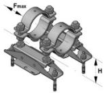 | MFP-CLD-I | 2223014 | 21 |
 | MFP-CH | 2223015 | 23 |
 | MFP -CH(M12) | 2223015 | 25 |
 | MFP-CHD | 2223120 | 27 |
 | MFP-CHD(M12) | 2223120 | 29 |
Fixed Points Light Without Sound Insulation
 | MFP-L | 2223121 | 31 |
 | MFP-L2 | 2223123 | 33 |
 | MFP-LD | 2223122 | 35 |
 | MFP-LD2 | 2223124 | 37 |
CONTENT AND OVERVIEW OF THIS MANUAL
| Product | Description | Item number | Page |
| Fixed Points Light With Sound Insulation | |||
 | MFP-L-I | 2223125 | 39 |
 | MFP-L2-I | 2223127 | 41 |
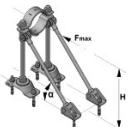 | MFP-LD-I | 2223126 | 43 |
 | MFP-LD2-I | 2223128 | 45 |
| Fixed Points Universal Without Sound Insulation | |||
 | MFP-UL | 2223129 | 47 |
 | MFP-UL2 | 2223131 | 49 |
 | MFP-ULD | 2223130 | 51 |
 | MFP-ULD2 | 2223132 | 53 |
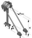 | MFP - UM | 2238272 | 55 |
 | MFP - UM2 | 2238273 | 57 |
 | MFP-UHD | 2223138 | 59 |
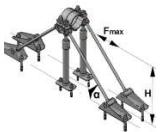 | MFP-UHD2 | 2223140 | 61 |
CONTENT AND OVERVIEW OF THIS MANUAL
| Product | Description | Item number | Page |
| Fixed Points Universal With Sound Insulation | |||
 | MFP-UL-I | 2223133 | 63 |
 | MFP-UL2-I | 2223135 | 65 |
 | MFP-ULD-I | 2223134 | 67 |
 | MFP-ULD2-I | 2223136 | 69 |
 | MFP-UM-I | 2238274 | 71 |
 | MFP-UM2-I | 2238275 | 73 |
| Fixed Points Fixed On Concrete Column | |||
 | MFP-CL-I | 2223018 | 75 |
| Fixed Points Fixed on MI / MIQ Structure | |||
 | MFP-CL-I | 2223018 | 77 |
 | MFP-CL-I | 2223018 | 79 |
 | MFP-CLD-I | 2223014 | 81 |
 | MFP-CLD-I | 223014 | 83 |
 | MFP-CH | 2223015 | 85 |
CONTENT AND OVERVIEW OF THIS MANUAL
| Product | Description | Item number | Page |
| Fixed Points Fixed on MI / MIQ Structure | |||
 | MFP-CH | 2223015 | 87 |
 | MFP-CHD | 2223120 | 89 |
 | MFP-CHD | 2223120 | 91 |
 | MFP-CHD | 2223120 | 93 |
| Fixed Points with longer than standard distances | |||
 | MFP-CSL | 2223016 | 95 |
 | MFP-CSL-I | 2223017 | 97 |
 | MFP-CL-I | 2223018 | 99 |
 | MFP-CLD-I | 2223014 | 101 |
| Pipe Clamps loading capacity | |||
 | MFP-PC | 103 | |
| Chilled Fixed Points overview | |||
 | KF Fixed points | 105 | |
 | Temperature influence | 107 | |
 | Fixed points fire resistance | 108 | |
FIXED POINT - TECHNICAL BACKGROUND INFORMATION
Technical challenges and how these dictate the product requirements
Heating
The major challenge when fastening heating pipes is thermal expansion of the pipe and its impact on pipe supports and the surroundings.
Thermal expansion leads to extension of the length of the pipe and depends on three basic parameters:

Examples of materials and their coefficients of expansion
| Material | Coefficient of expansion ,,α,, | Example for 10m, ΔT 50°C |
| Steel S 235 JR | 0.0000111 | 5.55 mm |
| Stainless steel | 0.000016 | 8.00 mm |
| Cast iron | 0.0000105 | 5.25 mm |
| Copper SF-Cu | 0.0000168 | 8.40 mm |
| Polyethylene PE 100 | 0.00018 | 90.0 mm |
FIXED POINT - TECHNICAL BACKGROUND INFORMATION
Expansion must be controlled
What can happen in the event of uncontrolled expansion – the impact of expansion on pipe supports
Example showing pipes on standing supports

Example showing suspended pipes

Both cases may lead to irreversible deformation, huge displacements, wrong load redistribution and ultimately to chain reactions causing pipe collapse.
FIXED POINT - TECHNICAL BACKGROUND INFORMATION
Uncontrolled expansion – impact on supports and surroundings
What can happen in the event of uncontrolled expansion – the impact of expansion on pipe supports
It may, by coincidence, have little effect, i.e. the pipe system is able to take up the movement.

An expanding element may exert pressure against the surrounding structure, which is not designed to carry these loads.

The expanding element exerts pressure between two rigid structures, thereby subjecting it to inner stress, possibly leading to breakage.

Ignoring the control of thermal expansion can have many more negative effects.
The cases above represent the majority of the problems encountered in the installation of pipes.
FIXED POINT - TECHNICAL BACKGROUND INFORMATION
Controlling expansion – methods used to control expansion
Expansion must be controlled. Its impact can then be predicted and calculated.
Fixed (anchor) point at one end, compensation for expansion at the other end.

A system for controlling expansion always consists of a set of fixed points and a means of compensation.
FIXED POINT - TECHNICAL BACKGROUND INFORMATION
Fixed points – placement - empirical rule
Generally, a good starting point is the following basic rule: For every straight section of pipe with a diameter of 2 1/2 " (76.1 mm) or more and a length of 10 m or more, expansion must be controlled by a fixed point in the middle of the run.

Plant room equipment with fixed point protection

Plant room equipment without fixed point protection

FIXED POINT - TECHNICAL BACKGROUND INFORMATION
Fixed points – loads
The basic function of a fixed (anchor) point is to anchor the pipe in a place where the building structure is designed to carry loads generated by expansion and to thus ensure zero movement of the pipe. This control of the pipe will generate certain loads due to several factors, depending on the type of compensation used:
Loads generated at a fixed point by natural compensation:
- FCR - Resistance to compensation (elbow, u-bend..)
- FFR - Friction at all pipe supports
Information about detailed calculation can obtain from Hilti engineering.

Loads generated at a fixed point by technical compensation:
- FSR - Load generated by spring rate of the expansion joint
- FTP - Media tubing pressure
- FFR - Friction at all pipe supports
Information about detailed calculation can be obtained from Hilti engineering.

FIXED POINT - TECHNICAL BACKGROUND INFORMATION
Hilti fixed point load transfer principles

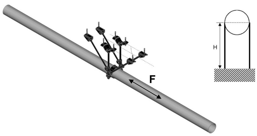
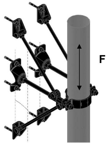
Most of the Hilti fixed point sets work on the stand and brace principle, thereby splitting the load into two parts on a triangular principle.


Braces in Hilti fixed point sets are made from M16 threaded rods.
The threaded rod must be subjected to tension only.
The orientation of the brace must reflect this.
The brace must be subjected to tension only.
In cases where you are not sure, or the brace can be even temporarily subjected to opposite loads (when the system is heating up or cooling down), we recommend that braces are fitted on both sides.

FIXED POINT - TECHNICAL BACKGROUND INFORMATION
Fixed point versus loading capacity of the structure
Placement of fixed points should always take the loading capacity of the building structure into account. The structural engineer responsible for the structure must always be consulted about the impact of the fixed point.
The cases mentioned below are examples of situations that could present a risk to the stability of the building structure or any other sub-structures.
The cases are explained on the basis of a fixed point load of 10 kN acting on an arm at a distance of 1m from the supporting material.

10 kN may exceed the spot loading capacity of a concrete slab and the loads acting in this way may pull out the entire anchor (fixed point).

Load transfer to the girder may subject it to torsion or other mechanisms that could impact its structural integrity.


Fixed Point On Concrete - MFP-CSL Fixed Point:
MFP-CSL without sound insulation
| 1 | 1 | MFP-PCFixed Point Pipe Ring | |
| 1x | MFP-PC 21-22 M20 2227599 | ||
| MFP-PC 25-27 M20 2227690 | |||
| MFP-PC 28-30 M20 2227691 | |||
| MFP-PC 31-33 M20 2227692 | |||
| MFP-PC 33.5-36 M20 2227693 | |||
| MFP-PC 39-41 M20 2227694 | |||
| MFP-PC 42-45 M20 2227695 | |||
| MFP-PC 47-50 M20 2227696 | |||
| MFP-PC 53-56 M20 2227697 | |||
| MFP-PC 57-61 M20 2227698 | |||
| MFP-PC 62-66 M20 2227699 | |||
| MFP-PC 68-72 M20 2227700 | |||
| MFP-PC 73-78 M20 2227701 | |||
| MFP-PC 88-93 M20 2227702 | |||
| MFP-PC 100-105 M20 2227703 | |||
| MFP-PC 108-115 M20 2227704 | |||
| 2 | 2 | MFP-CSLFixed point set | |
| 1x | MFP-CSL set 2223016 | ||
 | |||
| 3 | 3 | Anchors | |
 | 2x | HUS3-H 10x90 35/15/5 2079914 | |
| or | |||
| 2x | HST3 M12x85 10/- 2113978 | ||
2
3
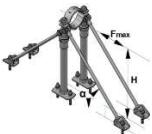
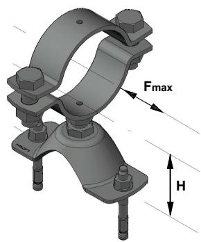
Resistance and limitations
Recommended resistance
(safety factor 1.5 included):
Fmax = 2.0 kN
Hmin = 85 mm
Hmax = 115 mm
height above ground to base of pipe
Validity of the capacity limits:
- Temperature limits: see the chapter ,,Temperature influence,,
of this manual,
- Published allowable loads for applications are based on static
loading conditions.
Disclamier:
- Load not applicable in any other than designated direction
- Load must be applied in the direction, that threaded rod is exposed
to tension (as pictured)
- Any lateral load expose must be individually evaluated

Application description
Heating - MFP-CSL fixed point
General comments
- Application subject to thermal expansion impact, no seismic, no fatigue impact
- Loading and load impact must always be compared with 3D capacity limits for every single part of the application
Application

Product lines
Fixed point sets
Threaded parts
Base material
Concrete
The Ground Truth image displays a single, solid horizontal line. According to Rule 2 (UNDERSCORE & LINE RULES), this is a stylistic or background line, not a placeholder underscore. Therefore, the OCR result must ignore it and output nothing or only meaningful text. The provided OCR content is "____", which consists of four underscores. This is an incorrect interpretation of the line as a placeholder, violating the rule that stylistic lines must be ignored. The OCR has hallucinated placeholder underscores where none exist in the GT. Hence, the OCR result is inconsistent with the Ground Truth.
Fixed Point On Concrete - MFP-CSL-I Fixed Point:
MFP-CSL-I with sound insulation
1 | 1 | MFP-PCFixed Point Pipe Ring | |
| 1x | MFP-PC 21-22 M20 | 2227599 | |
| MFP-PC 25-27 M20 | 2227690 | ||
| MFP-PC 28-30 M20 | 2227691 | ||
| MFP-PC 31-33 M20 | 2227692 | ||
| MFP-PC 33.5-36 M20 | 2227693 | ||
| MFP-PC 39-41 M20 | 2227694 | ||
| MFP-PC 42-45 M20 | 2227695 | ||
| MFP-PC 47-50 M20 | 2227696 | ||
| MFP-PC 53-56 M20 | 2227697 | ||
| MFP-PC 57-61 M20 | 2227698 | ||
| MFP-PC 62-66 M20 | 2227699 | ||
| MFP-PC 68-72 M20 | 2227700 | ||
| MFP-PC 73-78 M20 | 2227701 | ||
| MFP-PC 88-93 M20 | 2227702 | ||
| MFP-PC 100-105 M20 | 2227703 | ||
| MFP-PC 108-115 M20 | 2227704 | ||
Resistance and limitations
Recommended resistance
(safety factor 1.5 included):
Fmax = 2.0 kN
Hmin = 85 mm
Hmax = 115 mm
height above ground to base of pipe
Validity of the capacity limits:
- Temperature limits: see the chapter ,,Temperature influence,,
of this manual,
- Published allowable loads for applications are based on static
loading conditions.
Disclamier:
- Load not applicable in any other than designated direction
- Load must be applied in the direction, that threaded rod is exposed
to tension (as pictured)
- Any lateral load expose must be individually evaluated

 |

| Application description | Application | Product lines | Base material |
| Heating - MFP-CSL-I fixed point | Fixed point sets | Concrete | |
| General comments | Threaded parts | ||
| • Application subject to thermal expansion impact, no seismic, no fatigue impact | |||
| • Loading and load impact must always be compared with 3D capacity limits for every single part of the application |
Fixed Point On Concrete - MFP-CL-I Fixed Point:
MFP-CL-I with sound insulation
| 1 | 1 | MFP-PCFixed Point Pipe Ring | |
| 2x | MFP-PC 21-22 M20 2227599 | ||
| MFP-PC 25-27 M20 2227690 | |||
| MFP-PC 28-30 M20 2227691 | |||
| MFP-PC 31-33 M20 2227692 | |||
| MFP-PC 33.5-36 M20 2227693 | |||
| MFP-PC 39-41 M20 2227694 | |||
| MFP-PC 42-45 M20 2227695 | |||
| MFP-PC 47-50 M20 2227696 | |||
| MFP-PC 53-56 M20 2227697 | |||
| MFP-PC 57-61 M20 2227698 | |||
| MFP-PC 62-66 M20 2227699 | |||
| MFP-PC 68-72 M20 2227700 | |||
| MFP-PC 73-78 M20 2227701 | |||
| MFP-PC 88-93 M20 2227702 | |||
| MFP-PC 100-105 M20 2227703 | |||
| MFP-PC 108-115 M20 2227704 | |||
| MFP-PC 125-133 M20 2227705 | |||
| MFP-PC 134-142 M20 2227706 | |||
| MFP-PC 154-162 M20 2227707 | |||
| MFP-PC 162-170 M20 2227708 | |||
| 2 | 2 | MFP-CL-IFixed point set | |
| 1x | MFP-CL-I set 2223018 | ||
| 3 | 3 | Anchors | |
| 2x | HUS3-H 10x60 5/-/- 2079911or | ||
| 2x | HST3 M12x85 10/- 2113978 | ||
Alternative anchor points

Resistance and limitations
Recommended resistance
(safety factor 1.5 included):
Fmax = 4.0 kN
Hmin = 85 mm
Hmin = 115mm
height above ground to base of pipe
Validity of the capacity limits:
- Temperature limits: see the chapter „Temperature influence,,
of this manual,
- Published allowable loads for applications are based on static
loading conditions.
Disclamier:
- Load not applicable in any other than designated direction
- Load must be applied in the direction, that threaded rod is exposed
to tension (as pictured)
- Any lateral load expose must be individually evaluated


Application description
Heating - MFP-CL-I fixed point
General comments
- Application subject to thermal expansion impact, no seismic, no fatigue impact
- Loading and load impact must always be compared with 3D capacity limits for every single part of the application
Application
Product lines
Fixed point sets
Threaded parts
Base material
Concrete
Fixed Point On Concrete - MFP-CLD-I Fixed Point:
MFP-CL-I with sound insulation
| 1 | MFP-PC | |
| Fixed Point Pipe Ring | ||
| 2x | MFP-PC 73-78 M20 2227701 | |
| MFP-PC 88-93 M20 2227702 | ||
| MFP-PC 100-105 M20 2227703 | ||
| MFP-PC 108-115 M20 2227704 | ||
| MFP-PC 125-133 M20 2227705 | ||
| MFP-PC 134-142 M20 2227706 | ||
| MFP-PC 154-162 M20 2227707 | ||
| MFP-PC 162-170 M20 2227708 | ||
| MFP-PC 192-200 M20 2227709 | ||
| MFP-PC 213-221 M20 2227710 | ||
| 2 | 2 | MFP-CLD-I Fixed point set | |
| 1x | MFP-CLD-I set 2223014 | ||
| 3 | 3 | Anchors | |
| 4x | HUS3-H 10x60 5/-/- 2079911 or | ||
| 4x | HST3 M12x85 10/- 2113978 | ||
Alternative anchor points
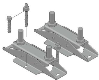
Resistance and limitations
Recommended resistance
(safety factor 1.5 included):
Fmax = 8.0kN
Hmin = 95 mm
Hmax = 175 mm
Height from base material to center of the pipe
Validity of the capacity limits:
- Temperature limits: see the chapter ,,Temperature influence,,
of this manual,
- Published allowable loads for applications are based on static
loading conditions.
Disclamier:
- Load not applicable in any other than designated direction
- Load must be applied in the direction, that threaded rod is exposed
to tension (as pictured)
- Any lateral load expose must be individually evaluated


| Application description | Application | Product lines | Base material |
| Heating - MFP-CLD-I fixed point | Fixed point sets | Concrete | |
| General comments | Threaded parts | ||
| • Application subject to thermal expansion impact, no seismic, no fatigue impact | |||
| • Loading and load impact must always be compared with 3D capacity limits for every single part of the application |
Fixed Point On Concrete - MFP-CH Fixed Point:
MFP-CH without sound insulation
| 1 | 1 | MFP-PCFixed Point Pipe Ring | |
| 3x | MFP-PC 21-22 M20 2227599 | ||
| MFP-PC 25-27 M20 2227690 | |||
| MFP-PC 28-30 M20 2227691 | |||
| MFP-PC 31-33 M20 2227692 | |||
| MFP-PC 33.5-36 M20 2227693 | |||
| MFP-PC 39-41 M20 2227694 | |||
| MFP-PC 42-45 M20 2227695 | |||
| MFP-PC 47-50 M20 2227696 | |||
| MFP-PC 53-56 M20 2227697 | |||
| MFP-PC 57-61 M20 2227698 | |||
| MFP-PC 62-66 M20 2227699 | |||
| MFP-PC 68-72 M20 2227700 | |||
| MFP-PC 73-78 M20 2227701 | |||
| MFP-PC 88-93 M20 2227702 | |||
| MFP-PC 100-105 M20 2227703 | |||
| MFP-PC 108-115 M20 2227704 | |||
| MFP-PC 125-133 M20 2227705 | |||
| MFP-PC 134-142 M20 2227706 | |||
| MFP-PC 154-162 M20 2227707 | |||
| MFP-PC 162-170 M20 2227708 | |||
| MFP-PC 192-200 M20 2227709 | |||
| MFP-PC 213-221 M20 2227710 | |||
| MFP-PC 242-250 M20 2227711 | |||
| MFP-PC 267-275 M20 2227712 | |||
| MFP-PC 318-326 M20 2227598 | |||
Resistance and limitations
Recommended resistance
(safety factor 1.5 included):
Fmax = 22 kN
Hmin = 115 mm
Hmax = 165 mm
height above ground to base of pipe
Validity of the capacity limits:
- Temperature limits: see the chapter ,,Temperature influence,,
of this manual,
- Published allowable loads for applications are based on static
loading conditions.
Disclamier:
- Load not applicable in any other than designated direction
- Load must be applied in the direction, that threaded rod is
exposed to tension (as pictured)
- Any lateral load expose must be individually evaluated

| 2 | 2 | MFP-CH Fixed point set | |
| 1x MFP-CH set | 2223015 | ||
| 3 | 3 | Anchors | |
| 2x HUS3-H 14x130 65/45/15 or 2x HST3 M16x135 35/15 | 2079923 2105858 | ||


Application description
Heating - MFP-CH fixed point
General comments
- Application subject to thermal expansion impact, no seismic, no fatigue impact
- Loading and load impact must always be compared with 3D capacity limits for every single part of the application
Application

Product lines
Fixed point sets
Threaded parts
Base material
Concrete
Fixed Point On Concrete - MFP-CH (M12) using alternative anchoring
MFP-CH without sound insulation
| 1 | 1 | MFP-PCFixed Point Pipe Ring | |
| 3x | MFP-PC 21-22 M20 2227599 | ||
| MFP-PC 25-27 M20 2227690 | |||
| MFP-PC 28-30 M20 2227691 | |||
| MFP-PC 31-33 M20 2227692 | |||
| MFP-PC 33.5-36 M20 2227693 | |||
| MFP-PC 39-41 M20 2227694 | |||
| MFP-PC 42-45 M20 2227695 | |||
| MFP-PC 47-50 M20 2227696 | |||
| MFP-PC 53-56 M20 2227697 | |||
| MFP-PC 57-61 M20 2227698 | |||
| MFP-PC 62-66 M20 2227699 | |||
| MFP-PC 68-72 M20 2227700 | |||
| MFP-PC 73-78 M20 2227701 | |||
| MFP-PC 88-93 M20 2227702 | |||
| MFP-PC 100-105 M20 2227703 | |||
| MFP-PC 108-115 M20 2227704 | |||
| MFP-PC 125-133 M20 2227705 | |||
| MFP-PC 134-142 M20 2227706 | |||
| MFP-PC 154-162 M20 2227707 | |||
| MFP-PC 162-170 M20 2227708 | |||
| MFP-PC 192-200 M20 2227709 | |||
| MFP-PC 213-221 M20 2227710 | |||
| MFP-PC 242-250 M20 2227711 | |||
| MFP-PC 267-275 M20 2227712 | |||
| MFP-PC 318-326 M20 2227598 | |||
Resistance and limitations
Recommended resistance
(safety factor 1.5 included):
Fmax = 12 kN
Hmin = 115 mm
Hmax = 165 mm
height above ground to base of pipe
Validity of the capacity limits:
- Temperature limits: see the chapter „Temperature influence,,
of this manual,
- Published allowable loads for applications are based on static
loading conditions.
Disclamier:
- Load not applicable in any other than designated direction
- Load must be applied in the direction, that threaded rod is
exposed to tension (as pictured)
- Any lateral load expose must be individually evaluated

| 2 | 2 | MFP-CH Fixed point set | |
| 1x MFP-CH set | 2223015 | ||
| 3 | 3 | Anchors | |
| 4x HUS3-H 10x90 35/15/5 or 4x HST3 M12x105 30/10 | 2079914 2105718 | ||


Application description
Heating - MFP-CH fixed point with alternative M12 anchor points
General comments
- Application subject to thermal expansion impact, no seismic, no fatigue impact
- Loading and load impact must always be compared with 3D capacity limits for every single part of the application
Application

Product lines
Fixed point sets
Threaded parts
Base material
Concrete
[Non-Text]
Fixed Point On Concrete - MFP-CHD Fixed Point:
MFP-CHD without sound insulation
| 1 | 1 | MFP-PCFixed Point Pipe Ring | |
| 3x | MFP-PC 73-78 M20 2227701 | ||
| MFP-PC 88-93 M20 2227702 | |||
| MFP-PC 100-105 M20 2227703 | |||
| MFP-PC 108-115 M20 2227704 | |||
| MFP-PC 125-133 M20 2227705 | |||
| MFP-PC 134-142 M20 2227706 | |||
| MFP-PC 154-162 M20 2227707 | |||
| MFP-PC 162-170 M20 2227708 | |||
| MFP-PC 192-200 M20 2227709 | |||
| MFP-PC 213-221 M20 2227710 | |||
Resistance and limitations
Recommended resistance
(safety factor 1.5 included):
Fmax = 44 kN
Hmin = 130 mmm
Hmax = 180mm
Height from base material to center of the pipe
Validity of the capacity limits:
- Temperature limits: see the chapter ,,Temperature influence,,
of this manual,
- Published allowable loads for applications are based on static
loading conditions.
Disclamier:
- Load not applicable in any other than designated direction
- Load must be applied in the direction, that threaded rod is
exposed to tension (as pictured)
- Any lateral load expose must be individually evaluated

| 2 | 2 | MFP-CHD Fixed point set | |
| 1x MFP-CHD set | 2238264 | ||
| 3 | 5 | Anchors | |
| 4x HUS3-H 14x130 65/45/15 or 4x HST3 M16x135 35/15 | 2079923 2105858 | ||


| Application description | Application | Product lines | Base material |
| Heating - MFP-CHD fixed point | Fixed point sets | Concrete | |
| General comments | Threaded parts | ||
| • Application subject to thermal expansion impact, no seismic, no fatigue impact | |||
| • Loading and load impact must always be compared with 3D capacity limits for every single part of the application |
Fixed Point On Concrete - MFP-CHD Fixed Point (M12) Fixed Point using alternative anchoring
MFP-CHD without sound insulation
| 1 | 1 | MFP-PCFixed Point Pipe Ring | |
| 3x | MFP-PC 73-78 M20 2227701 | ||
| MFP-PC 88-93 M20 2227702 | |||
| MFP-PC 100-105 M20 2227703 | |||
| MFP-PC 108-115 M20 2227704 | |||
| MFP-PC 125-133 M20 2227705 | |||
| MFP-PC 134-142 M20 2227706 | |||
| MFP-PC 154-162 M20 2227707 | |||
| MFP-PC 162-170 M20 2227708 | |||
| MFP-PC 192-200 M20 2227709 | |||
| MFP-PC 213-221 M20 2227710 | |||
Resistance and limitations
Recommended resistance
(safety factor 1.5 included):
Fmax = 24 kN
Hmin = 130 mmm
Hmax = 180mm
Height from base material to center of the pipe
Validity of the capacity limits:
- Temperature limits: see the chapter ,,Temperature influence,,
of this manual,
- Published allowable loads for applications are based on static
loading conditions.
Disclamier:
- Load not applicable in any other than designated direction
- Load must be applied in the direction, that threaded rod is
exposed to tension (as pictured)
- Any lateral load expose must be individually evaluated

| 2 | 2 | MFP-CHD Fixed point set | |
| 1x MFP-CHD set | 2238264 | ||
| 3 | 5 | Anchors | |
| 4x HUS3-H 10x60 5/-/- | 2079911 | ||
| or | |||
| 4x HST3 M12x85 10/- | 2113978 | ||


2 Fixed point set
| Application description | Application | Product lines | Base material |
| Heating - MFP-CHD fixed point with alternative anchor points | Fixed point sets | Concrete | |
| General comments | Threaded parts | ||
| • Application subject to thermal expansion impact, no seismic, no fatigue impact | |||
| • Loading and load impact must always be compared with 3D capacity limits for every single part of the application |
Fixed Point On Concrete - MFP-L Fixed Point:
MFP-L without sound insulation
1

1 MFP-PC
Fixed Point Pipe Ring
| 1x | MFP-PC 21-22 M20 | 2227599 |
| MFP-PC 25-27 M20 | 2227690 | |
| MFP-PC 28-30 M20 | 2227691 | |
| MFP-PC 31-33 M20 | 2227692 | |
| MFP-PC 33.5-36 M20 | 2227693 | |
| MFP-PC 39-41 M20 | 2227694 | |
| MFP-PC 42-45 M20 | 2227695 | |
| MFP-PC 47-50 M20 | 2227696 | |
| MFP-PC 53-56 M20 | 2227697 | |
| MFP-PC 57-61 M20 | 2227698 | |
| MFP-PC 62-66 M20 | 2227699 | |
| MFP-PC 68-72 M20 | 2227700 | |
| MFP-PC 73-78 M20 | 2227701 | |
| MFP-PC 88-93 M20 | 2227702 | |
| MFP-PC 100-105 M20 | 2227703 | |
| MFP-PC 108-115 M20 | 2227704 | |
| MFP-PC 125-133 M20 | 2227705 | |
| MFP-PC 134-142 M20 | 2227706 |
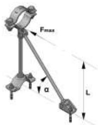
Resistance and limitations
Recommended resistance (safety factor 1.5 included):
Fmax = For loading capacity cases, see the reverse page
Hmin = 150
Hmax = 500
height above ground to base of pipe
α = 35°
α = 45°
Validity of the capacity limits:
- Temperature limits: see the chapter ,,Temperature influence,,
of this manual,
- Published allowable loads for applications are based on static loading conditions.
Disclamier:
- Load not applicable in any other than designated direction
- Load must be applied in the direction, that threaded rod is exposed
to tension (as pictured)
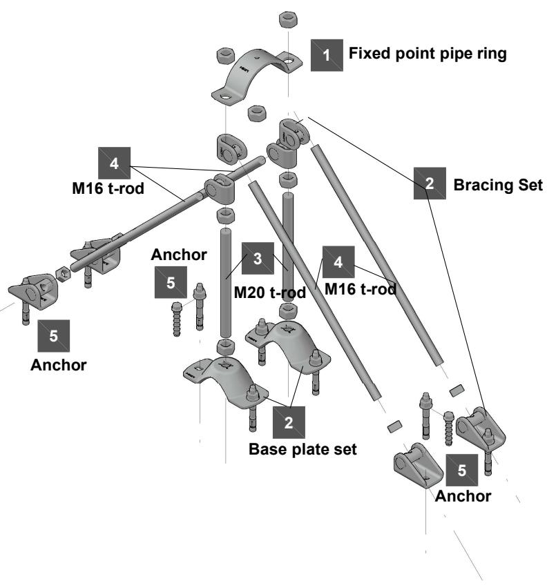
- Any lateral load expose must be individually evaluated

2

2
MFP-L
Fixed point set
1x MFP-L set 2223121
The set contains:
1x MFP-BR M16 bracing set
1x MFP-BP M20 base plate set
3

3
M20 Base Threaded Rod
1x AM20x1000 4.8 threaded rod 216425
4

4
M16 Bracing Threaded Rod
1x AM16x1000 4.8 threaded rod 216422
AM16x2000 4.8 threaded rod 216423
AM16x3000 4.8 threaded rod 216424
5
5
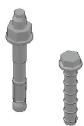
Anchors
3x HUS3-H 10x90 35/15/5 2079914
or
3x HST3 M12x85 10/- 2113978

1
Fixed point pipe ring

Application description
Heating - MFP-L fixed point
General comments
- Application subject to thermal expansion impact, no seismic, no fatigue impact
- Loading and load impact must always be compared with 3D capacity limits for every single part of the application
Application

Product lines
Fixed point sets
Threaded parts
Base material
Concrete
MFP-L recommended loading capacity limits
Hanging pipes - Recommended loading capacity

Supported pipes - Recommended loading capacity (Buckling check included)

| H [mm] up to | F [kN] |
| 0 | 4.000 |
| 50 | 4.000 |
| 100 | 4.000 |
| 150 | 4.000 |
| 200 | 4.000 |
| 250 | 4.000 |
| 300 | 4.000 |
| 350 | 4.000 |
| 400 | 4.000 |
| 450 | 4.000 |
| 500 | 4.000 |
Rising pipes - Recommended loading capacity

Fixed Point On Concrete - MFP-L2 Fixed Point:
MFP-L2 without sound insulation
| 1 | 1 | MFP-PCFixed Point Pipe Ring | |
| 1x | MFP-PC 21-22 M20 2227599 | ||
| MFP-PC 25-27 M20 2227690 | |||
| MFP-PC 28-30 M20 2227691 | |||
| MFP-PC 31-33 M20 2227692 | |||
| MFP-PC 33.5-36 M20 2227693 | |||
| MFP-PC 39-41 M20 2227694 | |||
| MFP-PC 42-45 M20 2227695 | |||
| MFP-PC 47-50 M20 2227696 | |||
| MFP-PC 53-56 M20 2227697 | |||
| MFP-PC 57-61 M20 2227698 | |||
| MFP-PC 62-66 M20 2227699 | |||
| MFP-PC 68-72 M20 2227700 | |||
| MFP-PC 73-78 M20 2227701 | |||
| MFP-PC 88-93 M20 2227702 | |||
| MFP-PC 100-105 M20 2227703 | |||
| MFP-PC 108-115 M20 2227704 | |||
| MFP-PC 125-133 M20 2227705 | |||
| MFP-PC 134-142 M20 2227706 | |||
Resistance and limitations
Recommended resistance (safety factor 1.5 included):
Fmax = For loading capacity cases, see the reverse page
Hmin = 190 mm
Hmax = 500 mm
height above ground to base of pipe
α = 35°
α = 45°
Validity of the capacity limits:
- Temperature limits: see the chapter ,,Temperature influence,,
of this manual,
- Published allowable loads for applications are based on static loading conditions.
Disclamier:
- Load not applicable in any other than designated direction
- Load must be applied in the direction, that threaded rod is exposed
to tension (as pictured)
- Any lateral load expose must be individually evaluated

 | 2 | MFP-L2Fixed point set |
| 1x | MFP-L2 set 2223123The set contain:2x MFP-BR M16 bracing set1x MFP-BP M20 base plate set | |
| 3 | M20 Base Threaded Rod | |
| 1x AM20x1000 4.8 threaded rod 216425 | ||
| 4 | M16 Bracing Threaded Rod | |
| 2x AM16x1000 4.8 threaded rod 216422AM16x2000 4.8 threaded rod 216423AM16x3000 4.8 threaded rod 216424 | ||
| 5 | Anchors | |
| 4x HUS3-H 10x90 35/15/5 or4x HST3 M12x85 10/- 2113978 |
2 MFP-L2 Fixed point set
3 M20 Base Threaded Rod
4 M16 Bracing Threaded Rod
5 Anchors

Application description
Heating - MFP-L2 fixed point
General comments
- Application subject to thermal expansion impact, no seismic, no fatigue impact
- Loading and load impact must always be compared with 3D capacity limits for every single part of the application
Application

Product lines
Fixed point sets
Threaded parts
Base material
Concrete
The Ground Truth image displays a single, solid horizontal line. According to Rule 2 (UNDERSCORE & LINE RULES), this is a stylistic or background line, not a placeholder underscore. Therefore, the OCR result must ignore it and output nothing or only meaningful text. The provided OCR content is "____", which consists of four underscores. This is an incorrect interpretation of the line as a placeholder, violating the rule that stylistic lines must be ignored. The OCR has hallucinated underscores where none should exist based on the GT's visual context. Hence, the OCR result is inconsistent with the Ground Truth.
Hanging pipes - Recommended loading capacity

Supported pipes - Recommended loading capacity (Buckling check included)

Rising pipes - Recommended loading capacity

| H [mm] up to | F [kN] |
| 0 | 4.000 |
| 50 | 4.000 |
| 100 | 4.000 |
| 150 | 4.000 |
| 200 | 4.000 |
| 250 | 4.000 |
| 300 | 4.000 |
| 350 | 4.000 |
| 400 | 4.000 |
| 450 | 4.000 |
| 500 | 4.000 |
Fixed Point On Concrete - MFP-LD Fixed Point:
MFP-LD without sound insulation
| 1 | 1 | MFP-PCFixed Point Pipe Ring | |
| 1x | MFP-PC 73-78 M20 2227701 | ||
| MFP-PC 88-93 M20 2227702 | |||
| MFP-PC 100-105 M20 2227703 | |||
| MFP-PC 108-115 M20 2227704 | |||
| MFP-PC 125-133 M20 2227705 | |||
| MFP-PC 134-142 M20 2227706 | |||
| MFP-PC 154-162 M20 2227707 | |||
| MFP-PC 162-170 M20 2227708 | |||
| MFP-PC 192-200 M20 2227709 | |||
| MFP-PC 213-221 M20 2227710 | |||
| MFP-PC 242-250 M20 2227711 | |||
| MFP-PC 267-275 M20 2227712 | |||
| MFP-PC 318-326 M20 2227598 | |||
Resistance and limitations
Recommended resistance (safety factor 1.5 included):
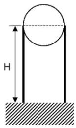
Fmax = For loading capacity cases, see the reverse page
Hmin = 190 mm
Hmax = 500 mm
Height from base material to center of the pipe
α = 35°
α = 45°
Validity of the capacity limits:
- Temperature limits: see the chapter ,,Temperature influence,,
of this manual,
- Published allowable loads for applications are based on static
loading conditions.
Disclaimer: Load not applicable in any other than designated direction.
- Load must be applied in the direction, that threaded rod is exposed.
to tension (as pictured)
- Any lateral load expose must be individually evaluated

 |

| Application description | Application | Product lines | Base material |
| Heating - MFP-LD fixed point | Fixed point sets | Concrete | |
| General comments | Threaded parts | ||
| • Application subject to thermal expansion impact, no seismic, no fatigue impact | |||
| • Loading and load impact must always be compared with 3D capacity limits for every single part of the application |
Hanging pipes - Recommended loading capacity

| H [mm] up to | F [kN] |
| 0 | 8.000 |
| 50 | 8.000 |
| 100 | 8.000 |
| 150 | 8.000 |
| 200 | 8.000 |
| 250 | 8.000 |
| 300 | 8.000 |
| 350 | 8.000 |
| 400 | 8.000 |
| 450 | 8.000 |
| 500 | 8.000 |
Supported pipes - Recommended loading capacity (Buckling check included)

| H [mm] up to | F [kN] | FB,max. [kN] |
| 0 | 8.000 | - |
| 50 | 8.000 | - |
| 100 | 8.000 | - |
| 150 | 8.000 | - |
| 200 | 8.000 | - |
| 250 | 8.000 | - |
| 300 | 8.000 | - |
| 350 | 8.000 | - |
| 400 | 8.000 | - |
| 450 | Fax | 11.971 |
| 500 | Fax | 10.715 |
Rising pipes - Recommended loading capacity

| H [mm] up to | F [kN] |
| 0 | 8.000 |
| 50 | 8.000 |
| 100 | 8.000 |
| 150 | 8.000 |
| 200 | 8.000 |
| 250 | 8.000 |
| 300 | 8.000 |
| 350 | 8.000 |
| 400 | 8.000 |
| 450 | 8.000 |
| 500 | 8.000 |
Fixed Point On Concrete - MFP-LD2 Fixed Point:
MFP-LD2 without sound insulation
1 | 1 | MFP-PCFixed Point Pipe Ring | |
| 1x | MFP-PC 73-78 M20 | 2227701 | |
| MFP-PC 88-93 M20 | 2227702 | ||
| MFP-PC 100-105 M20 | 2227703 | ||
| MFP-PC 108-115 M20 | 2227704 | ||
| MFP-PC 125-133 M20 | 2227705 | ||
| MFP-PC 134-142 M20 | 2227706 | ||
| MFP-PC 154-162 M20 | 2227707 | ||
| MFP-PC 162-170 M20 | 2227708 | ||
| MFP-PC 192-200 M20 | 2227709 | ||
| MFP-PC 213-221 M20 | 2227710 | ||
| MFP-PC 242-250 M20 | 2227711 | ||
| MFP-PC 267-275 M20 | 2227712 | ||
| MFP-PC 318-326 M20 | 2227598 | ||
Resistance and limitations
Recommended resistance (safety factor 1.5 included):
Fmax = For loading capacity cases, see the reverse page
Hmin = 190 mm
H = 500 mm
Height from base material to center of the pipe
α = 35°
α = 45°
Validity of the capacity limits:
- Temperature limits: see the chapter ,,Temperature influence,,
of this manual,
- Published allowable loads for applications are based on static
loading conditions.
Disclamier:
- Load not applicable in any other than designated direction
- Load must be applied in the direction, that threaded rod is exposed
to tension (as pictured)
- Any lateral load expose must be individually evaluated

 | 2 | MFP-LD2Fixed point set | |
| 1x | MFP-LD2 fixed point set | 2223124 | |
| The set contain: | |||
| 4x | MFP-BR M16 bracing set | ||
| 2x | MFP-BP M20 base plate set | ||
 | 3 | M20 Base Threaded Rod | |
| 2x | AM20x1000 4.8 threaded rod | 216425 | |
 | 4 | M16 Bracing Threaded Rod | |
| 4x | AM16x1000 4.8 threaded rod | 216422 | |
| AM16x2000 4.8 threaded rod | 216423 | ||
| AM16x3000 4.8 threaded rod | 216424 | ||
 | 5 | Anchors | |
| 8x | HUS3-H 10x90 35/15/5 | 2079914 | |
| or | |||
| 8x | HST3 M12x85 10/- | 2113978 | |
Application description
Heating - MFP-LD2 fixed point
General comments
- Application subject to thermal expansion impact, no seismic, no fatigue impact
- Loading and load impact must always be compared with 3D capacity limits for every single part of the application
Application

Product lines
Fixed point sets
Threaded parts
Base material
Concrete
Hanging pipes - Recommended loading capacity
| H [mm] up to | F [kN] |
| 0 | 8.000 |
| 50 | 8.000 |
| 100 | 8.000 |
| 150 | 8.000 |
| 200 | 8.000 |
| 250 | 8.000 |
| 300 | 8.000 |
| 350 | 8.000 |
| 400 | 8.000 |
| 450 | 8.000 |
| 500 | 8.000 |
Supported pipes - Recommended loading capacity (Buckling check included)

| H [mm] up to | F [kN] | FB,max. [kN] |
| 0 | 8.000 | - |
| 50 | 8.000 | - |
| 100 | 8.000 | - |
| 150 | 8.000 | - |
| 200 | 8.000 | - |
| 250 | 8.000 | - |
| 300 | 8.000 | - |
| 350 | 8.000 | - |
| 400 | 8.000 | - |
| 450 | Fax | 11.971 |
| 500 | Fax | 10.715 |
Rising pipes - Recommended loading capacity

| H [mm] up to | F [kN] |
| 0 | 8.000 |
| 50 | 8.000 |
| 100 | 8.000 |
| 150 | 8.000 |
| 200 | 8.000 |
| 250 | 8.000 |
| 300 | 8.000 |
| 350 | 8.000 |
| 400 | 8.000 |
| 450 | 8.000 |
| 500 | 8.000 |
Fixed Point On Concrete - MFP-L-I Fixed Point:
MFP-L-I with sound insulation
1 | 1 | MFP-PCFixed Point Pipe Ring | |
| 1x | MFP-PC 21-22 M20 | 2227599 | |
| MFP-PC 25-27 M20 | 2227690 | ||
| MFP-PC 28-30 M20 | 2227691 | ||
| MFP-PC 31-33 M20 | 2227692 | ||
| MFP-PC 33.5-36 M20 | 2227693 | ||
| MFP-PC 39-41 M20 | 2227694 | ||
| MFP-PC 42-45 M20 | 2227695 | ||
| MFP-PC 47-50 M20 | 2227696 | ||
| MFP-PC 53-56 M20 | 2227697 | ||
| MFP-PC 57-61 M20 | 2227698 | ||
| MFP-PC 62-66 M20 | 2227699 | ||
| MFP-PC 68-72 M20 | 2227700 | ||
| MFP-PC 73-78 M20 | 2227701 | ||
| MFP-PC 88-93 M20 | 2227702 | ||
| MFP-PC 100-105 M20 | 2227703 | ||
| MFP-PC 108-115 M20 | 2227704 | ||
| MFP-PC 125-133 M20 | 2227705 | ||
| MFP-PC 134-142 M20 | 2227706 | ||
Resistance and limitations
Recommended resistance (safety factor 1.5 included):
Fmax = For loading capacity cases, see the reverse page
Hmin = 150 mm
Hmax = 500 mm
height above ground to base of pipe
αmin = 35°
α = 45°
Validity of the capacity limits:
- Temperature limits: see the chapter ,,Temperature influence,,
of this manual,
- Published allowable loads for applications are based on static loading conditions.
Disclamier:
- Load not applicable in any other than designated direction
- Load must be applied in the direction, that threaded rod is exposed
to tension (as pictured)
- Any lateral load expose must be individually evaluated

| 2 | 2 | MFP-L-IFixed point set |
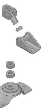
| 1x MFP-L-I set 2223125The set contains:1x MFP-BR-I M16 bracing set1x MFP-BP-I M20 base plate set | ||
  | ||
| 3 | 3 M20 Base Threaded Rod | |
| 1x AM20x1000 4.8 threaded rod 216425 | ||
| 4 | 4 M16 Bracing Threaded Rod | |
| 1x AM16x1000 4.8 threaded rod 216422AM16x2000 4.8 threaded rod 216423AM16x3000 4.8 threaded rod 216424 | ||
| 5 | 5 Anchors | |
| 3x HUS3-H 10x90 35/15/5 2079914or3x HST3 M12x85 10/- 2113978 |
2 MFP-L-I Fixed point set
| 3 | 3 | M20 Base Threaded Rod | |
| 1x | AM20x1000 4.8 threaded rod 216425 | ||
| 4 | 4 | M16 Bracing Threaded Rod | |
| 1x | AM16x1000 4.8 threaded rod 216422 | ||
| AM16x2000 4.8 threaded rod 216423 | |||
| AM16x3000 4.8 threaded rod 216424 | |||
| 5 | 5 | Anchors | |
| 3x | HUS3-H 10x90 35/15/5 2079914 | ||
| or | |||
| 3x | HST3 M12x85 10/- 2113978 |
3 M20 Base Threaded Rod
4 M16 Bracing Threaded Rod
5 Anchors

Application description
Heating - MFP-L-I fixed point
General comments
- Application subject to thermal expansion impact, no seismic, no fatigue impact
- Loading and load impact must always be compared with 3D capacity limits for every single part of the application
Application

Product lines
Fixed point sets
Threaded parts
Base material
Concrete

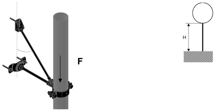
MFP-L-I recommended loading capacity limits
Hanging pipes - Recommended loading capacity

Supported pipes - Recommended loading capacity (Buckling check included)

Rising pipes - Recommended loading capacity
| H [mm] up to | F [kN] |
| 0 | 4.000 |
| 50 | 4.000 |
| 100 | 4.000 |
| 150 | 4.000 |
| 200 | 4.000 |
| 250 | 4.000 |
| 300 | 4.000 |
| 350 | 4.000 |
| 400 | 4.000 |
| 450 | 4.000 |
| 500 | 4.000 |
Fixed Point On Concrete - MFP-L2-I Fixed Point:
MFP-L2-I with sound insulation
1 | 1 | MFP-PCFixed Point Pipe Ring | |
| 1x | MFP-PC 21-22 M20 | 2227599 | |
| MFP-PC 25-27 M20 | 2227690 | ||
| MFP-PC 28-30 M20 | 2227691 | ||
| MFP-PC 31-33 M20 | 2227692 | ||
| MFP-PC 33.5-36 M20 | 2227693 | ||
| MFP-PC 39-41 M20 | 2227694 | ||
| MFP-PC 42-45 M20 | 2227695 | ||
| MFP-PC 47-50 M20 | 2227696 | ||
| MFP-PC 53-56 M20 | 2227697 | ||
| MFP-PC 57-61 M20 | 2227698 | ||
| MFP-PC 62-66 M20 | 2227699 | ||
| MFP-PC 68-72 M20 | 2227700 | ||
| MFP-PC 73-78 M20 | 2227701 | ||
| MFP-PC 88-93 M20 | 2227702 | ||
| MFP-PC 100-105 M20 | 2227703 | ||
| MFP-PC 108-115 M20 | 2227704 | ||
| MFP-PC 125-133 M20 | 2227705 | ||
| MFP-PC 134-142 M20 | 2227706 | ||
Resistance and limitations
Recommended resistance (safety factor 1.5 included):
Fmax = For loading capacity cases, see the reverse page
Hmin = 190
Hmax = 500
height above ground to base of pipe
α = 35°
α = 45°
Validity of the capacity limits:
- Temperature limits: see the chapter ,,Temperature influence,,
of this manual,
- Published allowable loads for applications are based on static leading conditions.
Loading conditions. Disclamier:
- Load not applicable in any other than designated direction
- Load must be applied in the direction, that threaded rod is exposed
to tension (as pictured)
- Any lateral load expose must be individually evaluated

2 | 2 | MFP-L2-IFixed point set |
| 1x | MFP-L2-I set 2223127The set contain:2x MFP-BR-I M16 bracing set1x MFP-BP M20 base plate set | |
| 3 | M20 Base Threaded Rod | |
| 1x AM20x1000 4.8 threaded rod 216425 | ||
| 4 | M16 Bracing Threaded Rod | |
| 2x AM16x1000 4.8 threaded rod 216422AM16x2000 4.8 threaded rod 216423AM16x3000 4.8 threaded rod 216424 | ||
| 5 | Anchors | |
| 4x HUS3-H 10x90 35/15/5 or 4x HST3 M12x85 10/- 2113978 |
| 2 | MFP-L2-I |
| Fixed point set |
| 3 | M20 Base Threaded Rod |
| 4 | M16 Bracing Threaded Rod |
| 5 | Anchors |

Application description
Heating - MFP-L2-I fixed point
General comments
- Application subject to thermal expansion impact, no seismic, no fatigue impact
- Loading and load impact must always be compared with 3D capacity limits for every single part of the application
Application

Product lines
Fixed point sets
Threaded parts
Base material
Concrete
The Ground Truth image displays a single, solid horizontal line. According to Rule 2 (UNDERSCORE & LINE RULES), this is a stylistic or background line, not a placeholder underscore. Therefore, the OCR result must ignore it and output nothing or only meaningful text. The provided OCR content is "____", which consists of four underscores. This is an incorrect interpretation of the line as a placeholder, violating the rule that stylistic lines must be ignored. The OCR has hallucinated underscores where none should exist based on the GT's visual context. Hence, the OCR result is inconsistent with the Ground Truth.
Hanging pipes - Recommended loading capacity

Supported pipes - Recommended loading capacity (Buckling check included)

Rising pipes - Recommended loading capacity

| H [mm] up to | F [kN] |
| 0 | 4.000 |
| 50 | 4.000 |
| 100 | 4.000 |
| 150 | 4.000 |
| 200 | 4.000 |
| 250 | 4.000 |
| 300 | 4.000 |
| 350 | 4.000 |
| 400 | 4.000 |
| 450 | 4.000 |
| 500 | 4.000 |
Fixed Point On Concrete - MFP-LD-I Fixed Point:
MFP-LD-I with sound insulation
| 1 | 1 | MFP-PCFixed Point Pipe Ring | |
| 1x | MFP-PC 73-78 M20 2227701MFP-PC 88-93 M20 2227702MFP-PC 100-105 M20 2227703MFP-PC 108-115 M20 2227704MFP-PC 125-133 M20 2227705MFP-PC 134-142 M20 2227706MFP-PC 154-162 M20 2227707MFP-PC 162-170 M20 2227708MFP-PC 192-200 M20 2227709MFP-PC 213-221 M20 2227710MFP-PC 242-250 M20 2227711MFP-PC 267-275 M20 2227712MFP-PC 318-326 M20 2227598 | ||
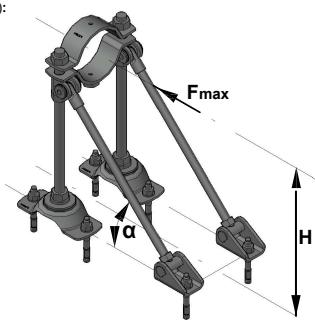
Resistance and limitations
Recommended resistance (safety factor 1.5 included):
Fmax = For loading capacity cases, see the reverse page
Hmin = 190 mm
Hmax = 500 mm
Height from base material to center of the pipe
α = 35°
α = 45°
Validity of the capacity limits:
- Temperature limits: see the chapter ,,Temperature influence,,
of this manual,
- Published allowable loads for applications are based on static loading conditions.
Disclamier:
- Load not applicable in any other than designated direction
- Load must be applied in the direction, that threaded rod is exposed
to tension (as pictured)
- Any lateral load expose must be individually evaluated
 |

| Application description | Application | Product lines | Base material |
| Heating - MFP-LD-I fixed point | Fixed point sets | Concrete | |
| General comments | Threaded parts | ||
| • Application subject to thermal expansion impact, no seismic, no fatigue impact | |||
| • Loading and load impact must always be compared with 3D capacity limits for every single part of the application |
Hanging pipes - Recommended loading capacity

| H [mm] up to | F [kN] |
| 0 | 8.000 |
| 50 | 8.000 |
| 100 | 8.000 |
| 150 | 8.000 |
| 200 | 8.000 |
| 250 | 8.000 |
| 300 | 8.000 |
| 350 | 8.000 |
| 400 | 8.000 |
| 450 | 8.000 |
| 500 | 8.000 |
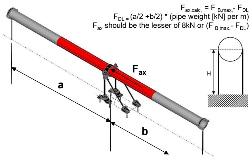
Supported pipes - Recommended loading capacity (Buckling check included)
| H [mm] up to | F [kN] | FB,max. [kN] |
| 0 | 8.000 | - |
| 50 | 8.000 | - |
| 100 | 8.000 | - |
| 150 | 8.000 | - |
| 200 | 8.000 | - |
| 250 | 8.000 | - |
| 300 | 8.000 | - |
| 350 | 8.000 | - |
| 400 | 8.000 | - |
| 450 | Fax | 11.971 |
| 500 | Fax | 10.715 |
Rising pipes - Recommended loading capacity


| H [mm] up to | F [kN] |
| 0 | 8.000 |
| 50 | 8.000 |
| 100 | 8.000 |
| 150 | 8.000 |
| 200 | 8.000 |
| 250 | 8.000 |
| 300 | 8.000 |
| 350 | 8.000 |
| 400 | 8.000 |
| 450 | 8.000 |
| 500 | 8.000 |
Fixed Point On Concrete - MFP-LD2-I Fixed Point:
MFP-LD2-I with sound insulation
1

1
MFP-PC
Fixed Point Pipe Ring
| 1x | MFP-PC 73-78 M20 | 2227701 |
| MFP-PC 88-93 M20 | 2227702 | |
| MFP-PC 100-105 M20 | 2227703 | |
| MFP-PC 108-115 M20 | 2227704 | |
| MFP-PC 125-133 M20 | 2227705 | |
| MFP-PC 134-142 M20 | 2227706 | |
| MFP-PC 154-162 M20 | 2227707 | |
| MFP-PC 162-170 M20 | 2227708 | |
| MFP-PC 192-200 M20 | 2227709 | |
| MFP-PC 213-221 M20 | 2227710 | |
| MFP-PC 242-250 M20 | 2227711 | |
| MFP-PC 267-275 M20 | 2227712 | |
| MFP-PC 318-326 M20 | 2227598 |
Resistance and limitations
Recommended resistance (safety factor 1.5 included):
Fmax = For loading capacity cases, see the reverse page
Hmin = 190
Hmax = 500
Height from base material to center of the pipe
α = 35°
α = 45°
Validity of the capacity limits:
- Temperature limits: see the chapter ,,Temperature influence,,
of this manual,
- Published allowable loads for applications are based on static loading conditions.
Disclamier:
- Load not applicable in any other than designated direction
- Load must be applied in the direction, that threaded rod is exposed to tension (as pictured)
- Any lateral load expose must be individually evaluated

2

2
MFP-LD2-IFixed point set
| 1x | MFP-LD2-I fixed point set | 2223128 |
| The set contain: | ||
| 4x | MFP-BR-I M16 bracing set | |
| 2x | MFP-BP-I M20 base plate set | |
3
3
M20 Base Threaded Rod
2x AM20x1000 4.8 threaded rod 216425
4

4
M16 Bracing Threaded Rod
| 4x AM16x1000 4.8 threaded rod | 216422 |
| AM16x2000 4.8 threaded rod | 216423 |
| AM16x3000 4.8 threaded rod | 216424 |
5

5
Anchors
| 8x HUS3-H 10x90 35/15/5 | 2079914 |
| or | |
| 8x HST3 M12x85 10/- | 2113978 |

Application description
Heating - MFP-LD2-I fixed point
General comments
- Application subject to thermal expansion impact, no seismic, no fatigue impact
- Loading and load impact must always be compared with 3D capacity limits for every single part of the application
Application
Product lines
Base material

Fixed point sets
Concrete
Threaded parts
Hanging pipes - Recommended loading capacity

| H [mm] up to | F [kN] |
| 0 | 8.000 |
| 50 | 8.000 |
| 100 | 8.000 |
| 150 | 8.000 |
| 200 | 8.000 |
| 250 | 8.000 |
| 300 | 8.000 |
| 350 | 8.000 |
| 400 | 8.000 |
| 450 | 8.000 |
| 500 | 8.000 |
Supported pipes - Recommended loading capacity (Buckling check included)

| H [mm] up to | F [kN] | FB,max. [kN] |
| 0 | 8.000 | - |
| 50 | 8.000 | - |
| 100 | 8.000 | - |
| 150 | 8.000 | - |
| 200 | 8.000 | - |
| 250 | 8.000 | - |
| 300 | 8.000 | - |
| 350 | 8.000 | - |
| 400 | 8.000 | - |
| 450 | Fax | 11.971 |
| 500 | Fax | 10.715 |
Rising pipes - Recommended loading capacity


| H [mm] up to | F [kN] |
| 0 | 8.000 |
| 50 | 8.000 |
| 100 | 8.000 |
| 150 | 8.000 |
| 200 | 8.000 |
| 250 | 8.000 |
| 300 | 8.000 |
| 350 | 8.000 |
| 400 | 8.000 |
| 450 | 8.000 |
| 500 | 8.000 |
Fixed Point On Concrete - MFP-UL Fixed Point:
MFP-UL without sound insulation
| 1 | 1 | MFP-PCFixed Point Pipe Ring | |
| 1x | MFP-PC 21-22 M20 2227599 | ||
| MFP-PC 25-27 M20 2227690 | |||
| MFP-PC 28-30 M20 2227691 | |||
| MFP-PC 31-33 M20 2227692 | |||
| MFP-PC 33.5-36 M20 2227693 | |||
| MFP-PC 39-41 M20 2227694 | |||
| MFP-PC 42-45 M20 2227695 | |||
| MFP-PC 47-50 M20 2227696 | |||
| MFP-PC 53-56 M20 2227697 | |||
| MFP-PC 57-61 M20 2227698 | |||
| MFP-PC 62-66 M20 2227699 | |||
| MFP-PC 68-72 M20 2227700 | |||
| MFP-PC 73-78 M20 2227701 | |||
| MFP-PC 88-93 M20 2227702 | |||
| MFP-PC 100-105 M20 2227703 | |||
| MFP-PC 108-115 M20 2227704 | |||
| MFP-PC 125-133 M20 2227705 | |||
| MFP-PC 134-142 M20 2227706 | |||
Resistance and limitations
Recommended resistance (safety factor 1.5 included):
Fmax = For loading capacity cases, see the reverse page
Hmin = 185 mm
Hmax = 2000 mm
height above ground to base of pipe
α = 35°
α = 45°
Validity of the capacity limits:
- Temperature limits: see the chapter ,,Temperature influence,,
of this manual,
- Published allowable loads for applications are based on static loading conditions.
Disclamier:
- Load not applicable in any other than designated direction
- Load must be applied in the direction, that threaded rod is exposed
to tension (as pictured)
- Any lateral load expose must be individually evaluated

 |
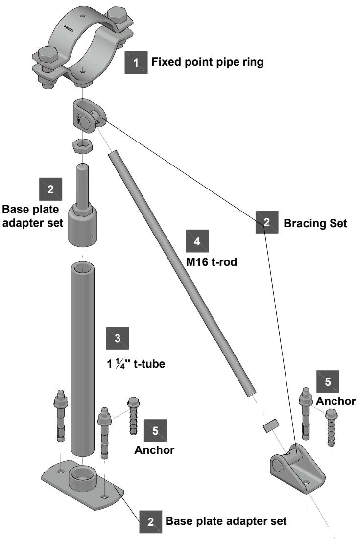
| Application description | Application | Product lines | Base material |
| Heating - MFP-UL fixed point | Fixed point sets | Concrete | |
| General comments | Threaded parts | ||
| • Application subject to thermal expansion impact, no seismic, no fatigue impact | |||
| • Loading and load impact must always be compared with 3D capacity limits for every single part of the application |

MFP-UL recommended loading capacity limits
Hanging pipes - Recommended loading capacity

Supported pipes - Recommended loading capacity (Buckling check included)

Rising pipes - Recommended loading capacity

| H [mm] up to | F [kN] |
| 0 | 4.000 |
| 500 | 4.000 |
| 550 | 4.000 |
| 600 | 4.000 |
| 650 | 4.000 |
| 700 | 4.000 |
| 750 | 4.000 |
| 800 | 4.000 |
| 850 | 4.000 |
| 900 | 4.000 |
| 950 | 4.000 |
| 1000 | 4.000 |
| 1100 | 4.000 |
| 1200 | 4.000 |
| 1250 | 4.000 |
| 1300 | 4.000 |
| 1400 | 4.000 |
| 1500 | 4.000 |
| 1600 | 4.000 |
| 1750 | 4.000 |
| 1800 | 4.000 |
| 1900 | 4.000 |
| 2000 | 4.000 |
Fixed Point On Concrete - MFP-UL2 Fixed Point:
MFP-UL2 without sound insulation
| 1 | 1 | MFP-PCFixed Point Pipe Ring | |
| 1x | MFP-PC 21-22 M20 2227599 | ||
| MFP-PC 25-27 M20 2227690 | |||
| MFP-PC 28-30 M20 2227691 | |||
| MFP-PC 31-33 M20 2227692 | |||
| MFP-PC 33.5-36 M20 2227693 | |||
| MFP-PC 39-41 M20 2227694 | |||
| MFP-PC 42-45 M20 2227695 | |||
| MFP-PC 47-50 M20 2227696 | |||
| MFP-PC 53-56 M20 2227697 | |||
| MFP-PC 57-61 M20 2227698 | |||
| MFP-PC 62-66 M20 2227699 | |||
| MFP-PC 68-72 M20 2227700 | |||
| MFP-PC 73-78 M20 2227701 | |||
| MFP-PC 88-93 M20 2227702 | |||
| MFP-PC 100-105 M20 2227703 | |||
| MFP-PC 108-115 M20 2227704 | |||
| MFP-PC 125-133 M20 2227705 | |||
| MFP-PC 134-142 M20 2227706 | |||
Resistance and limitations
Recommended resistance (safety factor 1.5 included):
Fmax = For loading capacity cases, see the reverse page
Hmin = 225 mm
Hmax = 2000 mm
height above ground to base of pipe
α = 35°
α = 45°
Validity of the capacity limits:
- Temperature limits: see the chapter ,,Temperature influence,,
of this manual,
- Published allowable loads for applications are based on static loading conditions.
Disclamier:
- Load not applicable in any other than designated direction
- Load must be applied in the direction, that threaded rod is exposed
to tension (as pictured)
- Any lateral load expose must be individually evaluated

 | 2 | MFP-UL2 Fixed point set |
| 1x | MFP-UL2 set 2223131The set contains:2x MFP-BR M16 bracing set1x MFP-BPA 11/4 base plate adapter set | |
| 3 | 11/4" Threaded Tube | |
| 1x GR-G 11/4"x 2000 4.6threaded tube 248532 | ||
| 4 | M16 Bracing Threaded Rod | |
| 2x AM16x1000 4.8 threaded rod 216422AM16x2000 4.8 threaded rod 216423AM16x3000 4.8 threaded rod 216424 | ||
| 5 | Anchors | |
| 4x HUS3-H 10x90 35/15/5 or 4x HST3 M12x85 10/- 2113978 |
MFP-UL2 Fixed point set
3 1 ¼" Threaded Tube
4 M16 Bracing Threaded Rod
5 Anchors
1 Fixed point pipe ring

Application description
Heating - MFP-UL2 fixed point
General comments
- Application subject to thermal expansion impact, no seismic, no fatigue impact
- Loading and load impact must always be compared with 3D capacity limits for every single part of the application
Application

Product lines
Fixed point sets
Threaded parts
Base material
Concrete
The Ground Truth image displays a single, solid horizontal line. According to Rule 2 (UNDERSCORE & LINE RULES), this is a stylistic or background line, not a placeholder underscore. Therefore, the OCR result must ignore it and output nothing or only meaningful text. The provided OCR content is "____", which consists of four underscores. This is an incorrect interpretation of the line as a placeholder, violating the rule that stylistic lines must be ignored. The OCR has hallucinated underscores where none should exist based on the GT's visual context. Hence, the OCR result is inconsistent with the Ground Truth.

MFP-UL2 recommended loading capacity limits
Hanging pipes - Recommended loading capacity
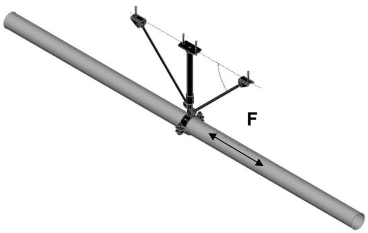

Supported pipes - Recommended loading capacity (Buckling check included)


Rising pipes - Recommended loading capacity


| H [mm] up to | F [kN] |
| 0 | 4.000 |
| 500 | 4.000 |
| 550 | 4.000 |
| 600 | 4.000 |
| 650 | 4.000 |
| 700 | 4.000 |
| 750 | 4.000 |
| 800 | 4.000 |
| 850 | 4.000 |
| 900 | 4.000 |
| 950 | 4.000 |
| 1000 | 4.000 |
| 1100 | 4.000 |
| 1200 | 4.000 |
| 1250 | 4.000 |
| 1300 | 4.000 |
| 1400 | 4.000 |
| 1500 | 4.000 |
| 1600 | 4.000 |
| 1750 | 4.000 |
| 1800 | 4.000 |
| 1900 | 4.000 |
| 2000 | 4.000 |
Fixed Point On Concrete - MFP-ULD Fixed Point:
MFP-ULD without sound insulation
1

1
MFP-PC
Fixed Point Pipe Ring
| 1x | MFP-PC 73-78 M20 | 2227701 |
| MFP-PC 88-93 M20 | 2227702 | |
| MFP-PC 100-105 M20 | 2227703 | |
| MFP-PC 108-115 M20 | 2227704 | |
| MFP-PC 125-133 M20 | 2227705 | |
| MFP-PC 134-142 M20 | 2227706 | |
| MFP-PC 154-162 M20 | 2227707 | |
| MFP-PC 162-170 M20 | 2227708 | |
| MFP-PC 192-200 M20 | 2227709 | |
| MFP-PC 213-221 M20 | 2227710 | |
| MFP-PC 242-250 M20 | 2227711 | |
| MFP-PC 267-275 M20 | 2227712 | |
| MFP-PC 318-326 M20 | 2227598 |
Resistance and limitations
Recommended resistance (safety factor 1.5 included):
Fmax = For loading capacity cases, see the reverse page
Hmin = 185 mm
Hmax = 2000 mm
Height from base material to center of the pipe
α = 35°
α = 45°
Validity of the capacity limits:
- Temperature limits: see the chapter ,,Temperature influence,, of this manual,.
- Published allowable loads for applications are based on static loading conditions.
Disclamier:
- Load not applicable in any other than designated direction
- Load must be applied in the direction, that threaded rod is exposed to tension (as pictured)
- Any lateral load expose must be individually evaluated

2

2
MFP-ULD Fixed point set
1x MFP-ULD set 2223130
The set contains:
2x MFP-BR M16 bracing set
2x MFP-BPA 1 1/4 base plate adapter set
3

3
1 1/4 " Threaded Tube
2x GR-G 1 1/4 "x 2000 4.6 threaded tube 248532
4

4
M16 Bracing Threaded Rod
2x AM16x1000 4.8 threaded rod 216422 AM16x2000 4.8 threaded rod 216423 AM16x3000 4.8 threaded rod 216424
5

5
Anchors
6x HUS3-H 10x90 35/15/5 2079914 or 6x HST3 M12x85 10/- 2113978
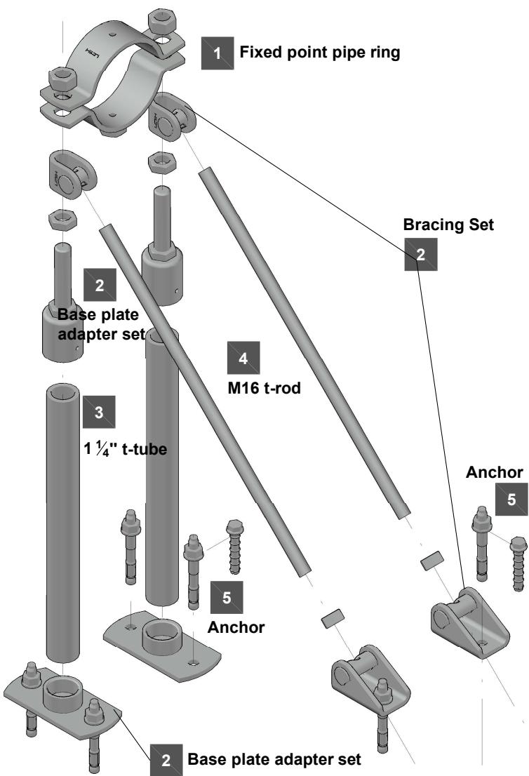
Application description
Heating - MFP-ULD fixed point
General comments
- Application subject to thermal expansion impact, no seismic, no fatigue impact
- Loading and load impact must always be compared with 3D capacity limits for every single part of the application
Application

Product lines
Fixed point sets
Threaded parts
Base material
Concrete
Hanging pipes - Recommended loading capacity


Supported pipes - Recommended loading capacity (Buckling check included)
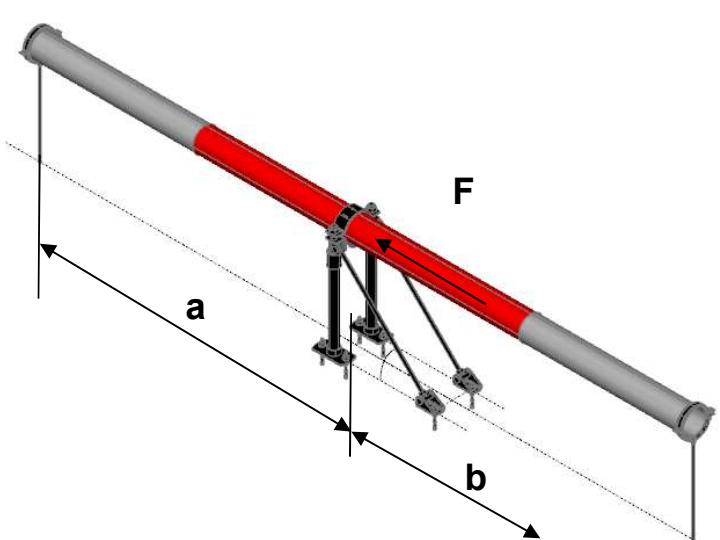

Rising pipes - Recommended loading capacity


| H [mm] up to | F [kN] |
| 0 | 8.000 |
| 500 | 8.000 |
| 550 | 8.000 |
| 600 | 8.000 |
| 650 | 8.000 |
| 700 | 8.000 |
| 750 | 8.000 |
| 800 | 8.000 |
| 850 | 8.000 |
| 900 | 8.000 |
| 950 | 8.000 |
| 1000 | 8.000 |
| 1100 | 8.000 |
| 1200 | 8.000 |
| 1250 | 8.000 |
| 1300 | 8.000 |
| 1400 | 8.000 |
| 1500 | 8.000 |
| 1600 | 8.000 |
| 1750 | 8.000 |
| 1800 | 8.000 |
| 1900 | 8.000 |
| 2000 | 8.000 |
Fixed Point On Concrete - MFP-ULD2 Fixed Point:
MFP-ULD2 without sound insulation
1

1 MFP-PC
Fixed Point Pipe Ring
| 1x | MFP-PC 73-78 M20 | 2227701 |
| MFP-PC 88-93 M20 | 2227702 | |
| MFP-PC 100-105 M20 | 2227703 | |
| MFP-PC 108-115 M20 | 2227704 | |
| MFP-PC 125-133 M20 | 2227705 | |
| MFP-PC 134-142 M20 | 2227706 | |
| MFP-PC 154-162 M20 | 2227707 | |
| MFP-PC 162-170 M20 | 2227708 | |
| MFP-PC 192-200 M20 | 2227709 | |
| MFP-PC 213-221 M20 | 2227710 | |
| MFP-PC 242-250 M20 | 2227711 | |
| MFP-PC 267-275 M20 | 2227712 | |
| MFP-PC 318-326 M20 | 2227598 |
Resistance and limitations
Recommended resistance (safety factor 1.5 included):
Fmax = For loading capacity cases, see the reverse page
Lmin = 225 mm
Lmax = 2000 mm
Height from base material to center of the pipe
α = 35°
α = 45°
Validity of the capacity limits:
- Temperature limits: see the chapter ,,Temperature influence,,
of this manual,
- Published allowable loads for applications are based on static
loading conditions.
Disclamier:
- Load not applicable in any other than designated direction
- Load must be applied in the direction, that threaded rod is exposed
to tension (as pictured)
- Any lateral load expose must be individually evaluated

2

2
MFP-ULD2 Fixed point set
1x MFP-ULD2 set 2223132
The set contains:
4x MFP-BR M16 bracing set
2x MFP-BPA 1 1/4 base plate adapter set
3

3
1 1/4 " Threaded Tube
2x GR-G 1 ¼"x 2000 4.6
threaded tube 248532
4

4
M16 Bracing Threaded Rod
4x AM16x1000 4.8 threaded rod 216422
AM16x2000 4.8 threaded rod 216423
AM16x3000 4.8 threaded rod 216424
5

5
Anchors
8x HUS3-H 10x90 35/15/5 2079914
or
8x HST3 M12x85 10/- 2113978
1
Fixed point pipe ring


Application description
Heating - MFP-ULD2 fixed point
General comments
- Application subject to thermal expansion impact, no seismic, no fatigue impact
- Loading and load impact must always be compared with 3D capacity limits for every single part of the application
Application
Product lines
Base material

Fixed point sets
Concrete
Threaded parts

MFP-ULD2 recommended loading capacity limits
Hanging pipes - Recommended loading capacity


Supported pipes - Recommended loading capacity (Buckling check included)


Rising pipes - Recommended loading capacity


| H [mm] up to | F [kN] |
| 0 | 8.000 |
| 500 | 8.000 |
| 550 | 8.000 |
| 600 | 8.000 |
| 650 | 8.000 |
| 700 | 8.000 |
| 750 | 8.000 |
| 800 | 8.000 |
| 850 | 8.000 |
| 900 | 8.000 |
| 950 | 8.000 |
| 1000 | 8.000 |
| 1100 | 8.000 |
| 1200 | 8.000 |
| 1250 | 8.000 |
| 1300 | 8.000 |
| 1400 | 8.000 |
| 1500 | 8.000 |
| 1600 | 8.000 |
| 1750 | 8.000 |
| 1800 | 8.000 |
| 1900 | 8.000 |
| 2000 | 8.000 |
Fixed Point On Concrete - MFP - UM Fixed Point:
MFP-UM without sound insulation
1 | 1 | MFP-PCFixed Point Pipe Ring | |
| 2x | MFP-PC 73-78 M20 2227701MFP-PC 88-93 M20 2227702MFP-PC 100-105 M20 2227703MFP-PC 108-115 M20 2227704MFP-PC 125-133 M20 2227705MFP-PC 134-142 M20 2227706MFP-PC 154-162 M20 2227707MFP-PC 162-170 M20 2227708MFP-PC 192-200 M20 2227709MFP-PC 213-221 M20 2227710MFP-PC 242-250 M20 2227711MFP-PC 267-275 M20 2227712MFP-PC 318-326 M20 2227598 | ||
2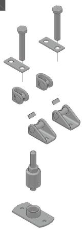 | 2 | MFP - UM Fixed point set | |
| 1x | MFP-UM set 2238272The set contains:2x MFP-BR M16 bracing set1x MFP-BPA 11/4 base plate adapter set1x MFP-PCA adapter | ||
| 3 | 3 | 11/4" Threaded Tube | |
| 1x GR-G 11/4" x 2000 4.6threaded tube 248532 | |||
| 4 | 4 | M16 Bracing Threaded Rod | |
| 2x AM16x1000 4.8 threaded rod 216422AM16x2000 4.8 threaded rod 216423AM16x3000 4.8 threaded rod 216424 | |||
| 5 | 5 | Anchors | |
| 4x HUS3-H 10x110 55/35/25 2079916or4x HST3 M12/105 30/10 2105718 | |||
| 3 | 3 | 1 1⁄4" Threaded Tube | ||
| 1x | GR-G 1 1⁄4"x 2000 4.6 threaded tube | 248532 | ||
| 4 | 4 | M16 Bracing Threaded Rod | ||
| 2x | AM16x1000 4.8 threaded rod | 216422 | ||
| AM16x2000 4.8 threaded rod | 216423 | |||
| AM16x3000 4.8 threaded rod | 216424 | |||
| 5 | 5 | Anchors | ||
| 4x | HUS3-H 10x110 55/35/25 | 2079916 | ||
| or | ||||
| 4x | HST3 M12/105 30/10 | 2105718 | ||
Resistance and limitations
Recommended resistance (safety factor 1.5 included):
Fmax = For loading capacity cases, see the reverse page
Hmin = 175mm
Hmax = 2000mm
height above ground to base of pipe
α = 35°
α = 45°
Validity of the capacity limits:
- Temperature limits: see the chapter ,,Temperature influence,,
of this manual,
- Published allowable loads for applications are based on static loading conditions.
Disclamier:
- Load not applicable in any other than designated direction
- Load must be applied in the direction, that threaded rod is exposed
to tension (as pictured)
- Any lateral load expose must be individually evaluated


Application description
Heating - MFP-UM fixed point
General comments
- Application subject to thermal expansion impact, no seismic, no fatigue impact
- Loading and load impact must always be compared with 3D capacity limits for every single part of the application
Application

Product lines
Fixed point sets
Threaded parts
Base material
Concrete
The Ground Truth image displays a single, solid horizontal line. According to Rule 2 (UNDERSCORE & LINE RULES), this is a stylistic or background line, not a placeholder underscore. Therefore, the OCR result must ignore it and output nothing or only meaningful text. The provided OCR content is "____", which consists of four underscores. This is an incorrect interpretation of the line as a placeholder, violating the rule that stylistic lines must be ignored. The OCR has hallucinated underscores where none should exist based on the GT's visual context. Hence, the OCR result is inconsistent with the Ground Truth.

MFP-UM recommended loading capacity limits
Hanging pipes - Recommended loading capacity


Rising pipes - Recommended loading capacity


| H [mm] up to | F [kN] |
| 0 | 14.000 |
| 500 | 14.000 |
| 550 | 14.000 |
| 600 | 14.000 |
| 650 | 14.000 |
| 700 | 14.000 |
| 750 | 14.000 |
| 800 | 14.000 |
| 850 | 14.000 |
| 900 | 14.000 |
| 950 | 14.000 |
| 1000 | 14.000 |
| 1100 | 13.123 |
| 1200 | 11.869 |
| 1250 | 11.316 |
| 1300 | 10.804 |
| 1400 | 9.889 |
| 1500 | 9.095 |
| 1600 | 8.401 |
| 1750 | 7.512 |
| 1800 | 7.249 |
| 1900 | 6.767 |
| 2000 | 6.334 |
Supported pipes - Recommended loading capacity (Buckling check included)

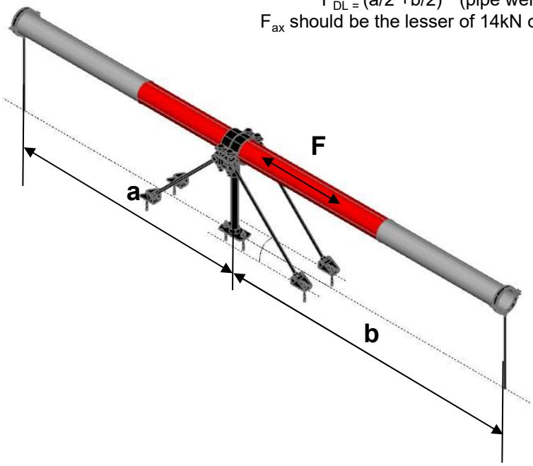
F _ ax, calc. = F _ B, max. - F _ DL
FDL = (a/2 + b/2) * (pipe weight [kN] per m)
Fax should be the lesser of 14kN or ( FB,max.-FDL )

| H [mm] up to | F [kN] | FB,max. [kN] |
| 0 | 14.000 | |
| 500 | 14.000 | |
| 550 | 14.000 | |
| 600 | 14.000 | |
| 650 | 14.000 | |
| 700 | 14.000 | |
| 750 | 14.000 | |
| 800 | 14.000 | |
| 850 | Fax | 17.477 |
| 900 | Fax | 16.425 |
| 950 | Fax | 15.477 |
| 1000 | Fax | 14.618 |
| 1100 | Fax | 13.123 |
| 1200 | Fax | 11.869 |
| 1250 | Fax | 11.316 |
| 1300 | Fax | 10.804 |
| 1400 | Fax | 9.889 |
| 1500 | Fax | 9.095 |
| 1600 | Fax | 8.401 |
| 1750 | Fax | 7.512 |
| 1800 | Fax | 7.249 |
| 1900 | Fax | 6.767 |
| 2000 | Fax | 6.334 |
Fixed Point On Concrete - MFP - UM2 Fixed Point:
MFP-UM2 without sound insulation
| 1 | 1 | MFP-PCFixed Point Pipe Ring | |
 | 2x | MFP-PC 73-78 M20 2227701MFP-PC 88-93 M20 2227702MFP-PC 100-105 M20 2227703MFP-PC 108-115 M20 2227704MFP-PC 125-133 M20 2227705MFP-PC 134-142 M20 2227706MFP-PC 154-162 M20 2227707MFP-PC 162-170 M20 2227708MFP-PC 192-200 M20 2227709MFP-PC 213-221 M20 2227710MFP-PC 242-250 M20 2227711MFP-PC 267-275 M20 2227712MFP-PC 318-326 M20 2227598 | |
| 2 | 2 | MFP - UM2 Fixed point set | |
| 1x | MFP-UM2 set 2238273The set contains:4x MFP-BR M16 bracing set1x MFP-BPA 11/4 base plate adapter set2x MFP-PCA adapter | ||
| 3 | 3 | 11/4" Threaded Tube | |
| 1x | GR-G 11/4" x 2000 4.6threaded tube 248532 | ||
| 4 | 4 | M16 Bracing Threaded Rod | |
| 4x | AM16x1000 4.8 threaded rod 216422AM16x2000 4.8 threaded rod 216423AM16x3000 4.8 threaded rod 216424 | ||
| 5 | 5 | Anchors | |
| 6x | HUS3-H 10x110 55/35/25 2079916or6 HST3 M12/105 30/10 2105718 | ||
| 2 | 2 | MFP - UM2 Fixed point set | |
| 1x MFP-UM2 set 2238273The set contains:4x MFP-BR M16 bracing set1x MFP-BPA 11/4 base plate adapter set2x MFP-PCA adapter | |||
| 3 | 3 | 11/4" Threaded Tube | |
| 1x GR-G 11/4" x 2000 4.6threaded tube 248532 | |||
| 4 | 4 | M16 Bracing Threaded Rod | |
| 4x AM16x1000 4.8 threaded rod 216422AM16x2000 4.8 threaded rod 216423AM16x3000 4.8 threaded rod 216424 | |||
| 5 | 5 | Anchors | |
| 6x HUS3-H 10x110 55/35/25 or6 HST3 M12/105 30/10 2105718 | |||
Resistance and limitations
Recommended resistance (safety factor 1.5 included):
Fmax = For loading capacity cases, see the reverse page
Hmin = 175mm
Hmax = 2000mm
height above ground to base of pipe
α=35°
α = 45°
Validity of the capacity limits:
- Temperature limits: see the chapter ,,Temperature influence,,
of this manual,
- Published allowable loads for applications are based on static
loading conditions.
Disclamier:
- Load not applicable in any other than designated direction
- Load must be applied in the direction, that threaded rod is exposed
to tension (as pictured)
- Any lateral load expose must be individually evaluated


| Application description | Application | Product lines | Base material |
| Heating - MFP-UM2 fixed point | Fixed point sets | Concrete | |
| General comments | Threaded parts | ||
| • Application subject to thermal expansion impact, no seismic, no fatigue impact | |||
| • Loading and load impact must always be compared with 3D capacity limits for every single part of the application |
Hanging pipes - Recommended loading capacity


Rising pipes - Recommended loading capacity


| H [mm] up to | F [kN] |
| 0 | 14.000 |
| 500 | 14.000 |
| 550 | 14.000 |
| 600 | 14.000 |
| 650 | 14.000 |
| 700 | 14.000 |
| 750 | 14.000 |
| 800 | 14.000 |
| 850 | 14.000 |
| 900 | 14.000 |
| 950 | 14.000 |
| 1000 | 14.000 |
| 1100 | 13.123 |
| 1200 | 11.869 |
| 1250 | 11.316 |
| 1300 | 10.804 |
| 1400 | 9.889 |
| 1500 | 9.095 |
| 1600 | 8.401 |
| 1750 | 7.512 |
| 1800 | 7.249 |
| 1900 | 6.767 |
| 2000 | 6.334 |
Supported pipes - Recommended loading capacity (Buckling check included)
F _ ax, calc. = F _ B, max. - F _ DL
FDL = (a/2 + b/2) * (pipe weight [kN] per m)
Fax should be the lesser of 14kN or ( FB,max.-FDL )

| H [mm] up to | F [kN] | FB,max. [kN] |
| 0 | 14.000 | |
| 500 | 14.000 | |
| 550 | 14.000 | |
| 600 | 14.000 | |
| 650 | 14.000 | |
| 700 | 14.000 | |
| 750 | 14.000 | |
| 800 | 14.000 | |
| 850 | Fax | 17.477 |
| 900 | Fax | 16.425 |
| 950 | Fax | 15.477 |
| 1000 | Fax | 14.618 |
| 1100 | Fax | 13.123 |
| 1200 | Fax | 11.869 |
| 1250 | Fax | 11.316 |
| 1300 | Fax | 10.804 |
| 1400 | Fax | 9.889 |
| 1500 | Fax | 9.095 |
| 1600 | Fax | 8.401 |
| 1750 | Fax | 7.512 |
| 1800 | Fax | 7.249 |
| 1900 | Fax | 6.767 |
| 2000 | Fax | 6.334 |
Fixed Point On Concrete - MFP-UHD Fixed Point:
MFP-UHD without sound insulation
1

1
MFP-PC
Fixed Point Pipe Ring
| 2x | MFP-PC 73-78 M20 | 2227701 |
| MFP-PC 88-93 M20 | 2227702 | |
| MFP-PC 100-105 M20 | 2227703 | |
| MFP-PC 108-115 M20 | 2227704 | |
| MFP-PC 125-133 M20 | 2227705 | |
| MFP-PC 134-142 M20 | 2227706 | |
| MFP-PC 154-162 M20 | 2227707 | |
| MFP-PC 162-170 M20 | 2227708 | |
| MFP-PC 192-200 M20 | 2227709 | |
| MFP-PC 213-221 M20 | 2227710 | |
| MFP-PC 242-250 M20 | 2227711 | |
| MFP-PC 267-275 M20 | 2227712 | |
| MFP-PC 318-326 M20 | 2227598 |
2

2
MFP-UHD Fixed point set
1x MFP-UHD set 2223138
The set contains:
2x MFP-BRH M16 bracing set
2x MFP-BPA 1 1/4 base plate adapter set
1x MFP-PCA M20 adapter
3

3
1 ¼" Threaded Tube
2x GR-G 1 1/4 "x 2000 4.6 threaded tube 248532
4

4
M16 Bracing Threaded Rod
2x AM16x1000 4.8 threaded rod 216422 AM16x2000 4.8 threaded rod 216423 AM16x3000 4.8 threaded rod 216424
5

5
Anchors
4x HUS3-H 10x110 55/35/25 2079916 4x HUS3-H 14x130 65/45/15 2079923 or 4x HST3 M12/105 30/10 2105718 4x HST3 M16x135 35/15 2105858

Resistance and limitations
Recommended resistance (safety factor 1.5 included):
Fmax = For loading capacity cases, see the reverse page
H = 200 mm
Hmax = 2000 mm
Height from base material to center of the pipe
α = 35°
α = 45°
Validity of the capacity limits:
- Temperature limits: see the chapter ,,Temperature influence,, of this manual,.
- Published allowable loads for applications are based on static loading conditions.
Disclamier:
- Load not applicable in any other than designated direction
- Load must be applied in the direction, that threaded rod is exposed to tension (as pictured)
- Any lateral load expose must be individually evaluated


Application description
Heating - MFP-UHD fixed point
General comments
- Application subject to thermal expansion impact, no seismic, no fatigue impact
- Loading and load impact must always be compared with 3D capacity limits for every single part of the application
Application
Product lines
Base material

Fixed point sets
Concrete
Threaded parts

MFP-UHD recommended loading capacity limits
Hanging pipes - Recommended loading capacity


Rising pipes - Recommended loading capacity


| H [mm] up to | F [kN] |
| 0 | 36.000 |
| 500 | 36.000 |
| 550 | 36.000 |
| 600 | 36.000 |
| 650 | 36.000 |
| 700 | 36.000 |
| 750 | 36.000 |
| 800 | 36.000 |
| 850 | 34.953 |
| 900 | 32.850 |
| 950 | 30.953 |
| 1000 | 29.235 |
| 1100 | 26.247 |
| 1200 | 23.739 |
| 1250 | 22.632 |
| 1300 | 21.608 |
| 1400 | 19.777 |
| 1500 | 18.190 |
| 1600 | 16.803 |
| 1750 | 15.024 |
| 1800 | 14.499 |
| 1900 | 13.534 |
| 2000 | 12.669 |
Supported pipes - Recommended loading capacity (Buckling check included)

F _ ax, calc. = F _ B, max. - F _ DL
FDL = (a/2 + b/2) * (pipe weight [kN] per m)
Fax should be the lesser of 36kN or ( FB,max.-FDL )

| H [mm] up to | F [kN] | FB,max. [kN] |
| 0 | 36.000 | |
| 500 | 36.000 | |
| 550 | 36.000 | |
| 600 | 36.000 | |
| 650 | 36.000 | |
| 700 | 36.000 | |
| 750 | Fax | 39.928 |
| 800 | Fax | 37.299 |
| 850 | Fax | 34.953 |
| 900 | Fax | 32.850 |
| 950 | Fax | 30.953 |
| 1000 | Fax | 29.235 |
| 1100 | Fax | 26.247 |
| 1200 | Fax | 23.739 |
| 1250 | Fax | 22.632 |
| 1300 | Fax | 21.608 |
| 1400 | Fax | 19.777 |
| 1500 | Fax | 18.190 |
| 1600 | Fax | 16.803 |
| 1750 | Fax | 15.024 |
| 1800 | Fax | 14.499 |
| 1900 | Fax | 13.534 |
| 2000 | Fax | 39.928 |
Fixed Point On Concrete - MFP-UHD2 Fixed Point:
MFP-UHD2 without sound insulation
| 1 | [MFP-PCFixed Point Pipe Ring] | |
 | 2x | MFP-PC 73-78 M20 2227701MFP-PC 88-93 M20 2227702MFP-PC 100-105 M20 2227703MFP-PC 108-115 M20 2227704MFP-PC 125-133 M20 2227705MFP-PC 134-142 M20 2227706MFP-PC 154-162 M20 2227707MFP-PC 162-170 M20 2227708MFP-PC 192-200 M20 2227709MFP-PC 213-221 M20 2227710MFP-PC 242-250 M20 2227711MFP-PC 267-275 M20 2227712MFP-PC 318-326 M20 2227598 |
| 2 | [MFP-UHD2 Fixed point set] | |
 | 1x | MFP-UHD2 set 2223139The set contains:4x MFP-BRH M16 bracing set2x MFP-BPA 11/4 base plate adapter set2x MFP-PCA M20 adapter |
| 3 | 11/4" Threaded Tube | |
 | 2x | GR-G 11/4"x 2000 4.6threaded tube 248532 |
| 4 | M16 Bracing Threaded Rod | |
 | 4x | AM16x1000 4.8 threaded rod 216422AM16x2000 4.8 threaded rod 216423AM16x3000 4.8 threaded rod 216424 |
| 5 | Anchors | |
 | 4x | HUS3-H 10x110 55/35/25 20799168x HUS3-H 14x130 65/45/15 2079923or4x HST3 M12x85 10/- 21139788x HST3 M16x135 35/15 2105858 |

Resistance and limitations
Recommended resistance (safety factor 1.5 included):
Fmax = For loading capacity cases, see the reverse page
Hmin = 200 mm
Lmax = 2000 mm
Height from base material to center of the pipe
α = 35°
α = 45°
Validity of the capacity limits:
- Temperature limits: see the chapter ,,Temperature influence,,
of this manual,
- Published allowable loads for applications are based on static loading conditions.
Disclamier:
- Load not applicable in any other than designated direction
- Load must be applied in the direction, that threaded rod is exposed
to tension (as pictured)
- Any lateral load expose must be individually evaluated


Application description
Heating - MFP-UHD2 fixed point
General comments
- Application subject to thermal expansion impact, no seismic, no fatigue impact
- Loading and load impact must always be compared with 3D capacity limits for every single part of the application
Application

Product lines
Fixed point sets
Threaded parts
Base material
Concrete
[Non-Text]

MFP-UHD2 recommended loading capacity limits
Hanging pipes - Recommended loading capacity
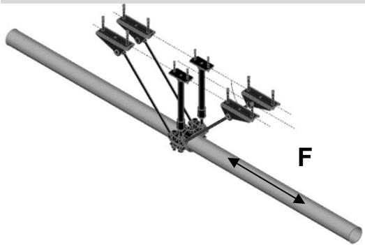

Rising pipes - Recommended loading capacity


| H [mm] up to | F [kN] |
| 0 | 36.000 |
| 500 | 36.000 |
| 550 | 36.000 |
| 600 | 36.000 |
| 650 | 36.000 |
| 700 | 36.000 |
| 750 | 36.000 |
| 800 | 36.000 |
| 850 | 34.953 |
| 900 | 32.850 |
| 950 | 30.953 |
| 1000 | 29.235 |
| 1100 | 26.247 |
| 1200 | 23.739 |
| 1250 | 22.632 |
| 1300 | 21.608 |
| 1400 | 19.777 |
| 1500 | 18.190 |
| 1600 | 16.803 |
| 1750 | 15.024 |
| 1800 | 14.499 |
| 1900 | 13.534 |
| 2000 | 12.669 |
Supported pipes - Recommended loading capacity (Buckling check included)

F _ ax, calc. = F _ B, max. - F _ DL
FDL = (a/2 + b/2) * (pipe weight [kN] per m)
Fax should be the lesser of 36kN or ( FB,max.-FDL )

| H [mm] up to | F [kN] | FB,max. [kN] |
| 0 | 36.000 | |
| 500 | 36.000 | |
| 550 | 36.000 | |
| 600 | 36.000 | |
| 650 | 36.000 | |
| 700 | 36.000 | |
| 750 | Fax | 39.928 |
| 800 | Fax | 37.299 |
| 850 | Fax | 34.953 |
| 900 | Fax | 32.850 |
| 950 | Fax | 30.953 |
| 1000 | Fax | 29.235 |
| 1100 | Fax | 26.247 |
| 1200 | Fax | 23.739 |
| 1250 | Fax | 22.632 |
| 1300 | Fax | 21.608 |
| 1400 | Fax | 19.777 |
| 1500 | Fax | 18.190 |
| 1600 | Fax | 16.803 |
| 1750 | Fax | 15.024 |
| 1800 | Fax | 14.499 |
| 1900 | Fax | 13.534 |
| 2000 | Fax | 39.928 |
Fixed Point On Concrete - MFP-UL-I Fixed Point:
MFP-UL-I with sound insulation
1

1 MFP-PC
Fixed Point Pipe Ring
| 1x | MFP-PC 21-22 M20 | 2227599 |
| MFP-PC 25-27 M20 | 2227690 | |
| MFP-PC 28-30 M20 | 2227691 | |
| MFP-PC 31-33 M20 | 2227692 | |
| MFP-PC 33.5-36 M20 | 2227693 | |
| MFP-PC 39-41 M20 | 2227694 | |
| MFP-PC 42-45 M20 | 2227695 | |
| MFP-PC 47-50 M20 | 2227696 | |
| MFP-PC 53-56 M20 | 2227697 | |
| MFP-PC 57-61 M20 | 2227698 | |
| MFP-PC 62-66 M20 | 2227699 | |
| MFP-PC 68-72 M20 | 2227700 | |
| MFP-PC 73-78 M20 | 2227701 | |
| MFP-PC 88-93 M20 | 2227702 | |
| MFP-PC 100-105 M20 | 2227703 | |
| MFP-PC 108-115 M20 | 2227704 | |
| MFP-PC 125-133 M20 | 2227705 | |
| MFP-PC 134-142 M20 | 2227706 |
Resistance and limitations
Recommended resistance (safety factor 1.5 included):
Fmax = For loading capacity cases, see the reverse page
Hmin = 185 mm
Hmax = 2000 mm
height above ground to base of pipe
α = 35°
α = 45°
Validity of the capacity limits:
- Temperature limits: see the chapter ,,Temperature influence,,
of this manual,
- Published allowable loads for applications are based on static loading conditions.
Disclamier:
- Load not applicable in any other than designated direction
- Load must be applied in the direction, that threaded rod is exposed
to tension (as pictured)
- Any lateral load expose must be individually evaluated

2

2
MFP-UL-I Fixed point set
1x MFP-UL-I set 2223133
The set contains:
1x MFP-BR M16 bracing set
1x MFP-BPA-I 1 1/4 base plate adapter set
3

3 1 1/4 " Threaded Tube
1x GR-G 1 1/4 "x 2000 4.6
threaded tube 248532
4

4
M16 Bracing Threaded Rod
1x AM16x1000 4.8 threaded rod 216422
AM16x2000 4.8 threaded rod 216423
AM16x3000 4.8 threaded rod 216424
5

5
Anchors
3x HUS3-H 10x90 35/15/5 2079914
or
3x HST3 M12x85 10/- 2113978

1
Fixed point pipe ring

Application description
Heating - MFP-UL-I fixed point
General comments
- Application subject to thermal expansion impact, no seismic, no fatigue impact
- Loading and load impact must always be compared with 3D capacity limits for every single part of the application
Application

Product lines
Fixed point sets
Threaded parts
Base material
Concrete

MFP-UL-I recommended loading capacity limits
Hanging pipes - Recommended loading capacity

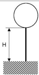
Supported pipes - Recommended loading capacity (Buckling check included)


Rising pipes - Recommended loading capacity

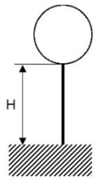
| H [mm] up to | F [kN] |
| 0 | 4.000 |
| 500 | 4.000 |
| 550 | 4.000 |
| 600 | 4.000 |
| 650 | 4.000 |
| 700 | 4.000 |
| 750 | 4.000 |
| 800 | 4.000 |
| 850 | 4.000 |
| 900 | 4.000 |
| 950 | 4.000 |
| 1000 | 4.000 |
| 1100 | 4.000 |
| 1200 | 4.000 |
| 1250 | 4.000 |
| 1300 | 4.000 |
| 1400 | 4.000 |
| 1500 | 4.000 |
| 1600 | 4.000 |
| 1750 | 4.000 |
| 1800 | 4.000 |
| 1900 | 4.000 |
| 2000 | 4.000 |
Fixed Point On Concrete - MFP-UL2-I Fixed Point:
MFP-UL2-I with sound insulation
1 | 1 | MFP-PCFixed Point Pipe Ring | |
| 1x | MFP-PC 21-22 M20 | 2227599 | |
| MFP-PC 25-27 M20 | 2227690 | ||
| MFP-PC 28-30 M20 | 2227691 | ||
| MFP-PC 31-33 M20 | 2227692 | ||
| MFP-PC 33.5-36 M20 | 2227693 | ||
| MFP-PC 39-41 M20 | 2227694 | ||
| MFP-PC 42-45 M20 | 2227695 | ||
| MFP-PC 47-50 M20 | 2227696 | ||
| MFP-PC 53-56 M20 | 2227697 | ||
| MFP-PC 57-61 M20 | 2227698 | ||
| MFP-PC 62-66 M20 | 2227699 | ||
| MFP-PC 68-72 M20 | 2227700 | ||
| MFP-PC 73-78 M20 | 2227701 | ||
| MFP-PC 88-93 M20 | 2227702 | ||
| MFP-PC 100-105 M20 | 2227703 | ||
| MFP-PC 108-115 M20 | 2227704 | ||
| MFP-PC 125-133 M20 | 2227705 | ||
| MFP-PC 134-142 M20 | 2227706 | ||
Resistance and limitations
Recommended resistance (safety factor 1.5 included):
Fmax = For loading capacity cases, see the reverse page
Hmin = 225 mm
Hmax = 2000 mm
height above ground to base of pipe
α = 35°
α = 45°
Validity of the capacity limits:
- Temperature limits: see the chapter ,,Temperature influence,,
of this manual,
- Published allowable loads for applications are based on static loading conditions.
Disclamier:
- Load not applicable in any other than designated direction
- Load must be applied in the direction, that threaded rod is exposed
to tension (as pictured)
- Any lateral load expose must be individually evaluated

| 2 | [MFKTY] | 2 | MFP-UL2-I Fixed point set |
| 1x | MFP-UL2-I set 2223135The set contains:2x MFP-BR-I M16 bracing set1x MFP-BPA-I 11/4 base plate adapter set | ||
| 3 | 3 | 11/4" Threaded Tube | |
| 1x | GR-G 11/4" x 2000 4.6 threaded tube 248532 | ||
| 4 | 4 | M16 Bracing Threaded Rod | |
| 2x | AM16x1000 4.8 threaded rod 216422AM16x2000 4.8 threaded rod 216423AM16x3000 4.8 threaded rod 216424 | ||
| 5 | 5 | Anchors | |
| 4x | HUS3-H 10x90 35/15/5 2079914or | ||
| 4x | HST3 M12x85 10/- 2113978 |
MFP-UL2-I Fixed point set
3 1 ¼" Threaded Tube
4 M16 Bracing Threaded Rod
5 Anchors
1 Fixed point pipe ring

Application description
Heating - MFP-UL2-I fixed point
General comments
- Application subject to thermal expansion impact, no seismic, no fatigue impact
- Loading and load impact must always be compared with 3D capacity limits for every single part of the application
Application

Product lines
Fixed point sets
Threaded parts
Base material
Concrete
The Ground Truth image displays a single, solid horizontal line. According to Rule 2 (UNDERSCORE & LINE RULES), this is a stylistic or background line, not a placeholder underscore. Therefore, the OCR result must ignore it and output nothing or only meaningful text. The provided OCR content is "____", which consists of four underscores. This is an incorrect interpretation of the line as a placeholder, violating the rule that stylistic lines must be ignored. The OCR has hallucinated underscores where none should exist based on the GT's visual context. Hence, the OCR result is inconsistent with the Ground Truth.

MFP-UL2-I recommended loading capacity limits
Hanging pipes - Recommended loading capacity


Supported pipes - Recommended loading capacity (Buckling check included)


Rising pipes - Recommended loading capacity
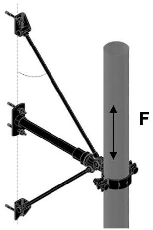

| H [mm] up to | F [kN] |
| 0 | 4.000 |
| 500 | 4.000 |
| 550 | 4.000 |
| 600 | 4.000 |
| 650 | 4.000 |
| 700 | 4.000 |
| 750 | 4.000 |
| 800 | 4.000 |
| 850 | 4.000 |
| 900 | 4.000 |
| 950 | 4.000 |
| 1000 | 4.000 |
| 1100 | 4.000 |
| 1200 | 4.000 |
| 1250 | 4.000 |
| 1300 | 4.000 |
| 1400 | 4.000 |
| 1500 | 4.000 |
| 1600 | 4.000 |
| 1750 | 4.000 |
| 1800 | 4.000 |
| 1900 | 4.000 |
| 2000 | 4.000 |
Fixed Point On Concrete - MFP-ULD-I Fixed Point:
MFP-ULD-I with sound insulation
1

1 MFP-PC
Fixed Point Pipe Ring
| 1x | MFP-PC 73-78 M20 | 2227701 |
| MFP-PC 88-93 M20 | 2227702 | |
| MFP-PC 100-105 M20 | 2227703 | |
| MFP-PC 108-115 M20 | 2227704 | |
| MFP-PC 125-133 M20 | 2227705 | |
| MFP-PC 134-142 M20 | 2227706 | |
| MFP-PC 154-162 M20 | 2227707 | |
| MFP-PC 162-170 M20 | 2227708 | |
| MFP-PC 192-200 M20 | 2227709 | |
| MFP-PC 213-221 M20 | 2227710 | |
| MFP-PC 242-250 M20 | 2227711 | |
| MFP-PC 267-275 M20 | 2227712 | |
| MFP-PC 318-326 M20 | 2227598 |
Resistance and limitations
Recommended resistance (safety factor 1.5 included):
Fmax = For loading capacity cases, see the reverse page
Hmin = 185 mm
Hmax = 2000 mm
Height from base material to center of the pipe
α = 35°
α = 45°
Validity of the capacity limits:
- Temperature limits: see the chapter ,,Temperature influence,,
of this manual,
- Published allowable loads for applications are based on static loading conditions.
Disclamier:
- Load not applicable in any other than designated direction
- Load must be applied in the direction, that threaded rod is exposed
to tension (as pictured)
- Any lateral load expose must be individually evaluated

2

2
MFP-ULD-I Fixed point set
1x MFP-ULD-I set 2223134
The set contains:
2x MFP-BR-I M16 bracing set
2x MFP-BPA-I 1 1/4 base plate adapter set
3

3
1 1/4 " Threaded Tube
2x GR-G 1 1/4 "x 2000 4.6
threaded tube 248532
4

4
M16 Bracing Threaded Rod
2x AM16x1000 4.8 threaded rod 216422
AM16x2000 4.8 threaded rod 216423
AM16x3000 4.8 threaded rod 216424
5

5
Anchors
6x HUS3-H 10x90 35/15/5 2079914
or
6x HST3 M12x85 10/- 2113978
1
Fixed point pipe ring

Application description
Heating - MFP-ULD-I fixed point
General comments
- Application subject to thermal expansion impact, no seismic, no fatigue impact
- Loading and load impact must always be compared with 3D capacity limits for every single part of the application
Application
Product lines
Base material

Fixed point sets
Concrete
Threaded parts
Hanging pipes - Recommended loading capacity
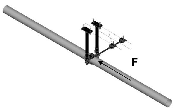

Supported pipes - Recommended loading capacity (Buckling check included)


Rising pipes - Recommended loading capacity


| H [mm] up to | F [kN] |
| 0 | 8.000 |
| 500 | 8.000 |
| 550 | 8.000 |
| 600 | 8.000 |
| 650 | 8.000 |
| 700 | 8.000 |
| 750 | 8.000 |
| 800 | 8.000 |
| 850 | 8.000 |
| 900 | 8.000 |
| 950 | 8.000 |
| 1000 | 8.000 |
| 1100 | 8.000 |
| 1200 | 8.000 |
| 1250 | 8.000 |
| 1300 | 8.000 |
| 1400 | 8.000 |
| 1500 | 8.000 |
| 1600 | 8.000 |
| 1750 | 8.000 |
| 1800 | 8.000 |
| 1900 | 8.000 |
| 2000 | 8.000 |
Fixed Point On Concrete - MFP-ULD2-I Fixed Point:
MFP-ULD2-I with sound insulation
1

1
MFP-PC
Fixed Point Pipe Ring
| 1x | MFP-PC 73-78 M20 | 2227701 |
| MFP-PC 88-93 M20 | 2227702 | |
| MFP-PC 100-105 M20 | 2227703 | |
| MFP-PC 108-115 M20 | 2227704 | |
| MFP-PC 125-133 M20 | 2227705 | |
| MFP-PC 134-142 M20 | 2227706 | |
| MFP-PC 154-162 M20 | 2227707 | |
| MFP-PC 162-170 M20 | 2227708 | |
| MFP-PC 192-200 M20 | 2227709 | |
| MFP-PC 213-221 M20 | 2227710 | |
| MFP-PC 242-250 M20 | 2227711 | |
| MFP-PC 267-275 M20 | 2227712 | |
| MFP-PC 318-326 M20 | 2227598 |
Resistance and limitations
Recommended resistance (safety factor 1.5 included):
Fmax = For loading capacity cases, see the reverse page
Hmin = 225 mm
Hmax = 2000 mm
Height from base material to center of the pipe
α = 35°
α = 45°
Validity of the capacity limits:
- Temperature limits: see the chapter ,,Temperature influence,,
of this manual,
- Published allowable loads for applications are based on static loading conditions.
Disclamier:
- Load not applicable in any other than designated direction
- Load must be applied in the direction, that threaded rod is exposed
to tension (as pictured)
- Any lateral load expose must be individually evaluated

2

2
MFP-ULD2-I Fixed point set
| 1x | MFP-ULD2-I set | 2223136 |
| The set contains: | ||
| 4x | MFP-BR-I M16 bracing set | |
| 2x | MFP-BPA-I 1 1/4 base plate adapter set | |
3

3
1 ¼" Threaded Tube
| 2x | GR-G 1 1/4 "x 2000 4.6 threaded tube | 248532 |
4
4
M16 Bracing Threaded Rod
| 4x AM16x1000 4.8 threaded rod | 216422 |
| AM16x2000 4.8 threaded rod | 216423 |
| AM16x3000 4.8 threaded rod | 216424 |
5

5
Anchors
| 8x | HUS3-H 10x90 35/15/5 | 2079914 |
| or | ||
| 8x | HST3 M12x85 10/- | 2113978 |
1
Fixed point pipe ring

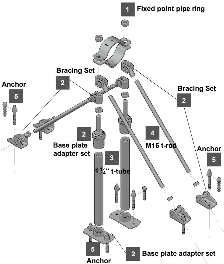
Application description
Heating - MFP-ULD2-I fixed point
General comments
- Application subject to thermal expansion impact, no seismic, no fatigue impact
- Loading and load impact must always be compared with 3D capacity limits for every single part of the application
Application
Product lines
Base material
Fixed point sets
Concrete
Threaded parts
Hanging pipes - Recommended loading capacity


Supported pipes - Recommended loading capacity (Buckling check included)


Rising pipes - Recommended loading capacity


| H [mm] up to | F [kN] |
| 0 | 8.000 |
| 500 | 8.000 |
| 550 | 8.000 |
| 600 | 8.000 |
| 650 | 8.000 |
| 700 | 8.000 |
| 750 | 8.000 |
| 800 | 8.000 |
| 850 | 8.000 |
| 900 | 8.000 |
| 950 | 8.000 |
| 1000 | 8.000 |
| 1100 | 8.000 |
| 1200 | 8.000 |
| 1250 | 8.000 |
| 1300 | 8.000 |
| 1400 | 8.000 |
| 1500 | 8.000 |
| 1600 | 8.000 |
| 1750 | 8.000 |
| 1800 | 8.000 |
| 1900 | 8.000 |
| 2000 | 8.000 |
Fixed Point On Concrete - MFP - UM - I Fixed Point:
MFP-UM-I with sound insulation

1
1 MFP-PC
Fixed Point Pipe Ring
| 2x | MFP-PC 73-78 M20 | 2227701 |
| MFP-PC 88-93 M20 | 2227702 | |
| MFP-PC 100-105 M20 | 2227703 | |
| MFP-PC 108-115 M20 | 2227704 | |
| MFP-PC 125-133 M20 | 2227705 | |
| MFP-PC 134-142 M20 | 2227706 | |
| MFP-PC 154-162 M20 | 2227707 | |
| MFP-PC 162-170 M20 | 2227708 | |
| MFP-PC 192-200 M20 | 2227709 | |
| MFP-PC 213-221 M20 | 2227710 | |
| MFP-PC 242-250 M20 | 2227711 | |
| MFP-PC 267-275 M20 | 2227712 | |
| MFP-PC 318-326 M20 | 2227598 |
2
2
MFP- UM-I Fixed point set

| 1x | MFP-UM - I set | 2238274 |
| The set contains: | ||
| 2x | MFP-BR-I M16 bracing set: | |
| 1x | MFP-BPA-I 1 1/4 base plate adapter set | |
| 1x | MFP-PCA adapter | |
3
3 1 1/4 " Threaded Tube
| 1x | GR-G 1 1/4 "x 2000 4.6 threaded tube | 248532 |
4
4
M16 Bracing Threaded Rod
| 2x AM16x1000 4.8 threaded rod | 216422 |
| AM16x2000 4.8 threaded rod | 216423 |
| AM16x3000 4.8 threaded rod | 216424 |
5
5
Anchors

| 4x | HUS3-H 10x90 35/15/5 | 2079914 |
| or | ||
| 4x | HST3 M12x85 10/- | 2113978 |
Resistance and limitations
Recommended resistance (safety factor 1.5 included):
Fmax = For loading capacity cases, see the reverse page
Hmin = 175mm
H = 2000mm
height above ground to base of pipe
α = 35°
α = 45°
Validity of the capacity limits:
- Temperature limits: see the chapter ,,Temperature influence,,
of this manual,
- Published allowable loads for applications are based on static loading conditions.
Disclamier
- Load not applicable in any other than designated direction
- Load must be applied in the direction, that threaded rod is exposed
to tension (as pictured)
- Any lateral load expose must be individually evaluated


Application description
Heating - MFP-UM-I fixed point
General comments
- Application subject to thermal expansion impact, no seismic, no fatigue impact
- Loading and load impact must always be compared with 3D capacity limits for every single part of the application
Application
Product lines
Base material

Fixed point sets
Concrete
Threaded parts

MFP-UM-I recommended loading capacity limits
Hanging pipes - Recommended loading capacity
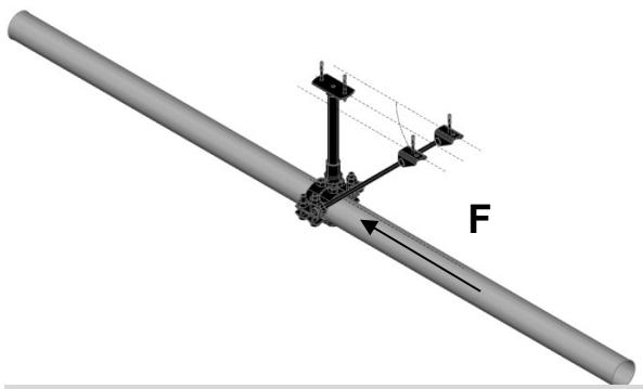

Rising pipes - Recommended loading capacity


| H [mm] up to | F [kN] |
| 0 | 14.000 |
| 500 | 14.000 |
| 550 | 14.000 |
| 600 | 14.000 |
| 650 | 14.000 |
| 700 | 14.000 |
| 750 | 14.000 |
| 800 | 14.000 |
| 850 | 14.000 |
| 900 | 14.000 |
| 950 | 14.000 |
| 1000 | 14.000 |
| 1100 | 13.123 |
| 1200 | 11.869 |
| 1250 | 11.316 |
| 1300 | 10.804 |
| 1400 | 9.889 |
| 1500 | 9.095 |
| 1600 | 8.401 |
| 1750 | 7.512 |
| 1800 | 7.249 |
| 1900 | 6.767 |
| 2000 | 6.334 |
Supported pipes - Recommended loading capacity (Buckling check included)

F _ ax, calc. = F _ B, max. - F _ DL
FDL = (a/2 + b/2) * (pipe weight [kN] per m)
Fax should be the lesser of 14kN or ( FB,max.-FDL )

| H [mm] up to | F [kN] | FB,max. [kN] |
| 0 | 14.000 | |
| 500 | 14.000 | |
| 550 | 14.000 | |
| 600 | 14.000 | |
| 650 | 14.000 | |
| 700 | 14.000 | |
| 750 | 14.000 | |
| 800 | 14.000 | |
| 850 | Fax | 17.477 |
| 900 | Fax | 16.425 |
| 950 | Fax | 15.477 |
| 1000 | Fax | 14.618 |
| 1100 | Fax | 13.123 |
| 1200 | Fax | 11.869 |
| 1250 | Fax | 11.316 |
| 1300 | Fax | 10.804 |
| 1400 | Fax | 9.889 |
| 1500 | Fax | 9.095 |
| 1600 | Fax | 8.401 |
| 1750 | Fax | 7.512 |
| 1800 | Fax | 7.249 |
| 1900 | Fax | 6.767 |
| 2000 | Fax | 6.334 |
Fixed Point On Concrete - MFP - UM2 - I Fixed Point:
MFP-UM2-I with sound insulation
1
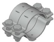
1 MFP-PC
Fixed Point Pipe Ring
| 2x | MFP-PC 73-78 M20 | 2227701 |
| MFP-PC 88-93 M20 | 2227702 | |
| MFP-PC 100-105 M20 | 2227703 | |
| MFP-PC 108-115 M20 | 2227704 | |
| MFP-PC 125-133 M20 | 2227705 | |
| MFP-PC 134-142 M20 | 2227706 | |
| MFP-PC 154-162 M20 | 2227707 | |
| MFP-PC 162-170 M20 | 2227708 | |
| MFP-PC 192-200 M20 | 2227709 | |
| MFP-PC 213-221 M20 | 2227710 | |
| MFP-PC 242-250 M20 | 2227711 | |
| MFP-PC 267-275 M20 | 2227712 | |
| MFP-PC 318-326 M20 | 2227598 |
2

2
MFP - UM2-I Fixed point set
| 1x | MFP-UM2 - I set | 2238275 |
| The set contains: | ||
| 4x | MFP-BR-I M16 bracing set: | |
| 1x | MFP-BPA-I 1 1/4 base plate adapter set | |
| 2x | MFP-PCA adapter | |
3

3
1 ¼" Threaded Tube
| 1x | GR-G 1 1/4 "x 2000 4.6 threaded tube | 248532 |
4

4
M16 Bracing Threaded Rod
| 4x AM16x1000 4.8 threaded rod | 216422 |
| AM16x2000 4.8 threaded rod | 216423 |
| AM16x3000 4.8 threaded rod | 216424 |
5

5
Anchors
| 6x | HUS3-H 10x90 35/15/5 | 2079914 |
| or | ||
| 6x | HST3 M12x85 10/- | 2113978 |
Resistance and limitations
Recommended resistance (safety factor 1.5 included):
Fmax = For loading capacity cases, see the reverse page
Hmin = 175mm
Hmax = 2000mm
height above ground to base of pipe
α = 35°
α = 45°
Validity of the capacity limits:
- Temperature limits: see the chapter ,,Temperature influence,,
of this manual,
- Published allowable loads for applications are based on static loading conditions.
Disclamier:
- Load not applicable in any other than designated direction
- Load must be applied in the direction, that threaded rod is exposed
to tension (as pictured)
- Any lateral load expose must be individually evaluated


Application description
Heating - MFP-UM2-I fixed point
General comments
- Application subject to thermal expansion impact, no seismic, no fatigue impact
- Loading and load impact must always be compared with 3D capacity limits for every single part of the application
Application
Product lines
Base material

Fixed point sets
Concrete
Threaded parts
Hanging pipes - Recommended loading capacity


Rising pipes - Recommended loading capacity


| H [mm] up to | F [kN] |
| 0 | 14.000 |
| 500 | 14.000 |
| 550 | 14.000 |
| 600 | 14.000 |
| 650 | 14.000 |
| 700 | 14.000 |
| 750 | 14.000 |
| 800 | 14.000 |
| 850 | 14.000 |
| 900 | 14.000 |
| 950 | 14.000 |
| 1000 | 14.000 |
| 1100 | 13.123 |
| 1200 | 11.869 |
| 1250 | 11.316 |
| 1300 | 10.804 |
| 1400 | 9.889 |
| 1500 | 9.095 |
| 1600 | 8.401 |
| 1750 | 7.512 |
| 1800 | 7.249 |
| 1900 | 6.767 |
| 2000 | 6.334 |
Supported pipes - Recommended loading capacity (Buckling check included)

F _ ax, calc. = F _ B, max. - F _ DL
FDL = (a/2 + b/2) * (pipe weight [kN] per m)
Fax should be the lesser of 14kN or ( FB,max.-FDL )

| H [mm] up to | F [kN] | FB,max. [kN] |
| 0 | 14.000 | |
| 500 | 14.000 | |
| 550 | 14.000 | |
| 600 | 14.000 | |
| 650 | 14.000 | |
| 700 | 14.000 | |
| 750 | 14.000 | |
| 800 | 14.000 | |
| 850 | Fax | 17.477 |
| 900 | Fax | 16.425 |
| 950 | Fax | 15.477 |
| 1000 | Fax | 14.618 |
| 1100 | Fax | 13.123 |
| 1200 | Fax | 11.869 |
| 1250 | Fax | 11.316 |
| 1300 | Fax | 10.804 |
| 1400 | Fax | 9.889 |
| 1500 | Fax | 9.095 |
| 1600 | Fax | 8.401 |
| 1750 | Fax | 7.512 |
| 1800 | Fax | 7.249 |
| 1900 | Fax | 6.767 |
| 2000 | Fax | 6.334 |
Fixed Point On Concrete - MFP-CL-I fixation on concrete column:
MFP-CL-I with sound insulation
| 1 | 1 | MFP-PCFixed Point Pipe Ring | |
 | 2x | MFP-PC 21-22 M20 | 2227599 |
| MFP-PC 25-27 M20 | 2227690 | ||
| MFP-PC 28-30 M20 | 2227691 | ||
| MFP-PC 31-33 M20 | 2227692 | ||
| MFP-PC 33.5-36 M20 | 2227693 | ||
| MFP-PC 39-41 M20 | 2227694 | ||
| MFP-PC 42-45 M20 | 2227695 | ||
| MFP-PC 47-50 M20 | 2227696 | ||
| MFP-PC 53-56 M20 | 2227697 | ||
| MFP-PC 57-61 M20 | 2227698 | ||
| MFP-PC 62-66 M20 | 2227699 | ||
| MFP-PC 68-72 M20 | 2227700 | ||
| MFP-PC 73-78 M20 | 2227701 | ||
| MFP-PC 88-93 M20 | 2227702 | ||
| MFP-PC 100-105 M20 | 2227703 | ||
| MFP-PC 108-115 M20 | 2227704 | ||
| MFP-PC 125-133 M20 | 2227705 | ||
| MFP-PC 134-142 M20 | 2227706 | ||
| MFP-PC 154-162 M20 | 2227707 | ||
| MFP-PC 162-170 M20 | 2227708 | ||
 | 2 | MFP-CL-I Fixed point set | |
| 1x | MFP-CL-I set | 2223018 | |
 | 3 | Anchors | |
| 2x | HUS3-H 10x60 5/-/- | 2079911 | |
| or | |||
| 2x | HST3 M12x85 10/- | 2113978 | |
Assembled application


| Application description | Application | Product lines | Base material |
| Heating - MFP-CL-I fixed point | Fixed point sets | Concrete | |
| General comments | Threaded parts | ||
| • Application subject to thermal expansion impact, no seismic, no fatigue impact | |||
| • Loading and load impact must always be compared with 3D capacity limits for every single part of the application |
Fixed Point On MI/MIQ structure - MFP-CL-I :
MFP-CL-I with sound insulation
| 1 | Brackets MIC-C90-DH for concrete | |
| Bracket (Cantilever arm) | ||
| 1x | MIC-C90-DH-500 | 2203572 |
| MIC-C90-DH-750 | 2203573 | |
| MIC-C90-DH-1000 | 2203574 | |
| MIC-C90-DH-1500 | 2203575 | |
| MIC-C90-DH-2000 | 2203576 | |
| Anchors | ||
| 4x | HST3-R M16x135 35/15 | 2105876 |
| 2 | Connector MIQC-90-MIMIQ-90 fixed on MI-90 | |
| 1x | MIQC-90-MI | 2140257 |
| Connector includes all connecting hardware | ||
| 3 | GirdersMIQ-90 | |
| MIQ-90 3m girder | 2119866 | |
| MIQ-90 6m girder | 2119867 | |
| 4 | Fixing the Fixed point set to MI girder | |
| Alternative 1 | ||
| MIQA-T t-bolt | 2120142 | |
| washer and nut included | ||
| Alternative 2 | ||
| MIQM-M12 wing nut | 2120275 | |
| M12x20-F hex. screw | 2131566 | |
| 5 | MFP-CL-I | |
| Fixed point set | ||
| MFP-CL-I set | 2223018 | |
| 6 | MFP-PC | |
| Fixed Point Pipe Ring | ||
| MFP-PC 21-22 M20 | 2227599 | |
| MFP-PC 25-27 M20 | 2227690 | |
| MFP-PC 28-30 M20 | 2227691 | |
| MFP-PC 31-33 M20 | 2227692 | |
| MFP-PC 33.5-36 M20 | 2227693 | |
| MFP-PC 39-41 M20 | 2227694 | |
| MFP-PC 42-45 M20 | 2227695 | |
| MFP-PC 47-50 M20 | 2227696 | |
| MFP-PC 53-56 M20 | 2227697 | |
| MFP-PC 57-61 M20 | 2227698 | |
| MFP-PC 62-66 M20 | 2227699 | |
| MFP-PC 68-72 M20 | 2227700 | |
| MFP-PC 73-78 M20 | 2227701 | |
| MFP-PC 88-93 M20 | 2227702 | |
| MFP-PC 100-105 M20 | 2227703 | |
| MFP-PC 108-115 M20 | 2227704 | |
| MFP-PC 125-133 M20 | 2227705 | |
| MFP-PC 134-142 M20 | 2227706 | |
| MFP-PC 154-162 M20 | 2227707 | |
| MFP-PC 162-170 M20 | 2227708 | |
Assembled application


This page of the manual does not provide any loading capacity or resistance of the structure.
The purpose of this page is an inspiration how to create fix point in non-standard cases.
In order to verify the whole structure, proper loads have to be applied and the whole structure has to be calculated
| Application description | Application | Product lines | Base material |
| Heating - MFP-CL-I fixed point fixed on MIQ structure | Fixed point sets | MI/MIQ structure | |
| General comments | Threaded parts | ||
| • Application subject to thermal expansion impact, no seismic, no fatigue impact | |||
| • Loading and load impact must always be compared with 3D capacity limits for every single part of the application |
Fixed Point On MI/MIQ structure - MFP-CL-I:
MFP-CL-I with sound insulation
| 1 | Brackets MIC-C90-DH for concrete | |
| Bracket (Cantilever arm) | ||
| 1x | MIC-C90-DH-500 | 2203572 |
| MIC-C90-DH-750 | 2203573 | |
| MIC-C90-DH-1000 | 2203574 | |
| MIC-C90-DH-1500 | 2203575 | |
| MIC-C90-DH-2000 | 2203576 | |
| Anchors | ||
| 4x | HST3-R M16x135 35/15 | 2105876 |
| 2 | Connector MIQC-90-MIMIQ-90 fixed on MI-90 | |
| 1x | MIQC-90-MI | 2140257 |
| Connector includes all connecting hardware | ||
| 3 | GirdersMIQ-90 | |
| MIQ-90 3m girder | 2119866 | |
| MIQ-90 6m girder | 2119867 | |
| 4 | Fixing the Fixed point set to MI girder | |
| Alternative 1 | ||
| MIQA-T t-bolt | 2120142 | |
| washer and nut included | ||
| Alternative 2 | ||
| MIQM-M12 wing nut | 2120275 | |
| M12x20-F hex. screw | 2131566 | |
| 5 | MFP-CL-IFixed point set | |
| MFP-CL-I set | 2223018 | |
| 6 | MFP-PCFixed Point Pipe Ring | |
| MFP-PC 21-22 M20 | 2227599 | |
| MFP-PC 25-27 M20 | 2227690 | |
| MFP-PC 28-30 M20 | 2227691 | |
| MFP-PC 31-33 M20 | 2227692 | |
| MFP-PC 33.5-36 M20 | 2227693 | |
| MFP-PC 39-41 M20 | 2227694 | |
| MFP-PC 42-45 M20 | 2227695 | |
| MFP-PC 47-50 M20 | 2227696 | |
| MFP-PC 53-56 M20 | 2227697 | |
| MFP-PC 57-61 M20 | 2227698 | |
| MFP-PC 62-66 M20 | 2227699 | |
| MFP-PC 68-72 M20 | 2227700 | |
| MFP-PC 73-78 M20 | 2227701 | |
| MFP-PC 88-93 M20 | 2227702 | |
| MFP-PC 100-105 M20 | 2227703 | |
| MFP-PC 108-115 M20 | 2227704 | |
| MFP-PC 125-133 M20 | 2227705 | |
| MFP-PC 134-142 M20 | 2227706 | |
| MFP-PC 154-162 M20 | 2227707 | |
| MFP-PC 162-170 M20 | 2227708 | |
Assembled application


This page of the manual does not provide any loading capacity or resistance of the structure.
The purpose of this page is an inspiration how to create fix point in non-standard cases.
In order to verify the whole structure, proper loads have to be applied and the whole structure has to be calculated
| Application description | Application | Product lines | Base material |
| Heating - MFP-CL-I fixed point fixed on MIQ structure | Fixed point sets | MI/MIQ structure | |
| General comments | Threaded parts | ||
| • Application subject to thermal expansion impact, no seismic, no fatigue impact | |||
| • Loading and load impact must always be compared with 3D capacity limits for every single part of the application |
Fixed Point On MI/MIQ structure - MFP-CLD-I:
MFP-CL-I with sound insulation
| 1 | Brackets MIC-C90-DH for concrete | |
| Bracket (Cantilever arm) | ||
| 1x | MIC-C90-DH-500 | 2203572 |
| MIC-C90-DH-750 | 2203573 | |
| MIC-C90-DH-1000 | 2203574 | |
| MIC-C90-DH-1500 | 2203575 | |
| MIC-C90-DH-2000 | 2203576 | |
| Anchors | ||
| 4x | HST3-R M16x135 35/15 | 2105876 |
| 2 | Connector MIQC-90-MIMIQ-90 fixed on MI-90 | |
| 1x | MIQC-90-MI | 2140257 |
| Connector includes all connecting hardware | ||
| 3 | Girders | |
| MIQ-90 | ||
| MIQ-90 3m girder | 2119866 | |
| MIQ-90 6m girder | 2119867 | |
| 4 | Fixing the Fixed point set to MI girder | |
| Alternative 1 | ||
| MIQA-T t-bolt | 2120142 | |
| washer and nut included | ||
| Alternative 2 | ||
| MIQM-M12 wing nut | 2120275 | |
| M12x20-F hex. screw | 2131566 | |
| 5 | MFP-CLD-IFixed point set | |
| 1x | MFP-CLD-I set | 2223014 |
| 6 | MFP-PC | |
| Fixed Point Pipe Ring | ||
| 2x | MFP-PC 73-78 M20 | 2227701 |
| MFP-PC 88-93 M20 | 2227702 | |
| MFP-PC 100-105 M20 | 2227703 | |
| MFP-PC 108-115 M20 | 2227704 | |
| MFP-PC 125-133 M20 | 2227705 | |
| MFP-PC 134-142 M20 | 2227706 | |
| MFP-PC 154-162 M20 | 2227707 | |
| MFP-PC 162-170 M20 | 2227708 | |
| MFP-PC 192-200 M20 | 2227709 | |
| MFP-PC 213-221 M20 | 2227710 | |
Assembled application
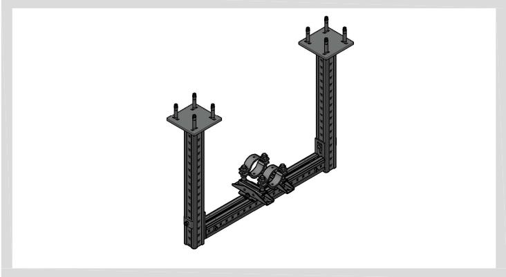

This page of the manual does not provide any loading capacity or resistance of the structure.
The purpose of this page is an inspiration how to create fix point in non-standard cases.
In order to verify the whole structure, proper loads have to be applied and the whole structure has to be calculated
| Application description | Application | Product lines | Base material |
| Heating - MFP-CLD-I fixed point | Fixed point sets | MI/MIQ structure | |
| General comments | Threaded parts | ||
| • Application subject to thermal expansion impact, no seismic, no fatigue impact | |||
| • Loading and load impact must always be compared with 3D capacity limits for every single part of the application |
Fixed Point On MI/MIQ structure - MFP-CLD-I:
MFP-CL-I with sound insulation
| 1 | Brackets MIC-C90-DH for concrete | |
| Bracket (Cantilever arm) | ||
| 1x | MIC-C90-DH-500 | 2203572 |
| MIC-C90-DH-750 | 2203573 | |
| MIC-C90-DH-1000 | 2203574 | |
| MIC-C90-DH-1500 | 2203575 | |
| MIC-C90-DH-2000 | 2203576 | |
| Anchors | ||
| 4x | HST3-R M16x135 35/15 | 2105876 |
| 2 | Connector MIQC-90-MIMIQ-90 fixed on MI-90 | |
| 1x | MIQC-90-MI | 2140257 |
| Connector includes all connecting hardware | ||
| 3 | Girders | |
| MIQ-90 | ||
| MIQ-90 3m girder | 2119866 | |
| MIQ-90 6m girder | 2119867 | |
| 4 | Fixing the Fixed point set to MI girder | |
| Alternative 1 | ||
| MIQA-T t-bolt | 2120142 | |
| washer and nut included | ||
| Alternative 2 | ||
| MIQM-M12 wing nut | 2120275 | |
| M12x20-F hex. screw | 2131566 | |
| 5 | MFP-CLD-IFixed point set | |
| 1x | MFP-CLD-I set | 2223014 |
| 6 | MFP-PC | |
| Fixed Point Pipe Ring | ||
| 2x | MFP-PC 73-78 M20 | 2227701 |
| MFP-PC 88-93 M20 | 2227702 | |
| MFP-PC 100-105 M20 | 2227703 | |
| MFP-PC 108-115 M20 | 2227704 | |
| MFP-PC 125-133 M20 | 2227705 | |
| MFP-PC 134-142 M20 | 2227706 | |
| MFP-PC 154-162 M20 | 2227707 | |
| MFP-PC 162-170 M20 | 2227708 | |
| MFP-PC 192-200 M20 | 2227709 | |
| MFP-PC 213-221 M20 | 2227710 | |
Assembled application
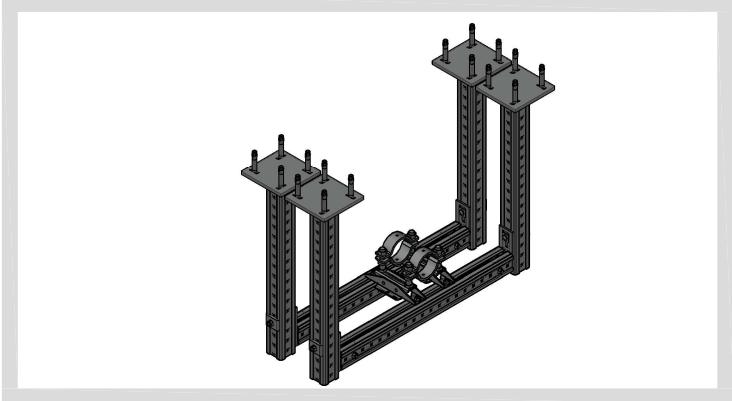

This page of the manual does not provide any loading capacity or resistance of the structure.
The purpose of this page is an inspiration how to create fix point in non-standard cases.
In order to verify the whole structure, proper loads have to be applied and the whole structure has to be calculated
| Application description | Application | Product lines | Base material |
| Heating - MFP-CLD-I fixed point on MI/MIQ structure | Fixed point sets | MI/MIQ structure | |
| General comments | Threaded parts | ||
| • Application subject to thermal expansion impact, no seismic, no fatigue impact | |||
| • Loading and load impact must always be compared with 3D capacity limits for every single part of the application |
Fixed Point Fixed On MI/MIQ System Structure - MFP-CH:
MFP-CH without sound insulation
Assembled application

| 1 | MFP-PC | |
| Fixed Point Pipe Ring | ||
| 3x | MFP-PC 21-22 M20 | 2227599 |
| MFP-PC 25-27 M20 | 2227690 | |
| MFP-PC 28-30 M20 | 2227691 | |
| MFP-PC 31-33 M20 | 2227692 | |
| MFP-PC 33.5-36 M20 | 2227693 | |
| MFP-PC 39-41 M20 | 2227694 | |
| MFP-PC 42-45 M20 | 2227695 | |
| MFP-PC 47-50 M20 | 2227696 | |
| MFP-PC 53-56 M20 | 2227697 | |
| MFP-PC 57-61 M20 | 2227698 | |
| MFP-PC 62-66 M20 | 2227699 | |
| MFP-PC 68-72 M20 | 2227700 | |
| MFP-PC 73-78 M20 | 2227701 | |
| MFP-PC 88-93 M20 | 2227702 | |
| MFP-PC 100-105 M20 | 2227703 | |
| MFP-PC 108-115 M20 | 2227704 | |
| MFP-PC 125-133 M20 | 2227705 | |
| MFP-PC 134-142 M20 | 2227706 | |
| MFP-PC 154-162 M20 | 2227707 | |
| MFP-PC 162-170 M20 | 2227708 | |
| MFP-PC 192-200 M20 | 2227709 | |
| MFP-PC 213-221 M20 | 2227710 | |
| MFP-PC 242-250 M20 | 2227711 | |
| MFP-PC 267-275 M20 | 2227712 | |
| MFP-PC 318-326 M20 | 2227598 | |
| 2 | MFP-CH Fixed point set | |
| 1x | MFP-CH set | 2223015 |
| 3 | U-bolts for fixationon MI-90 or MIQ-90 girder | |
| 1x | MIA-BO90-M12 connector | 304840 |
| 4 | U-bolts for fixationon MI-120 | |
| 1x | MIA-BO120-M12 connector | 304841 |

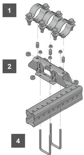
| Application description | Application | Product lines | Base material |
| Heating - MFP-CH fixed point fixed on MI / MIQ girders | Fixed point sets | MI/MIQ structure | |
| General comments | Threaded parts | ||
| • Application subject to thermal expansion impact, no seismic, no fatigue impact | |||
| • Loading and load impact must always be compared with 3D capacity limits for every single part of the application |
Fixed Point Fixed On MI/MIQ System Structure - MFP-CH:
MFP-CH without sound insulation
Assembled application

| 1 | MFP-PC | |
| Fixed Point Pipe Ring | ||
| 3x | MFP-PC 21-22 M20 | 2227599 |
| MFP-PC 25-27 M20 | 2227690 | |
| MFP-PC 28-30 M20 | 2227691 | |
| MFP-PC 31-33 M20 | 2227692 | |
| MFP-PC 33.5-36 M20 | 2227693 | |
| MFP-PC 39-41 M20 | 2227694 | |
| MFP-PC 42-45 M20 | 2227695 | |
| MFP-PC 47-50 M20 | 2227696 | |
| MFP-PC 53-56 M20 | 2227697 | |
| MFP-PC 57-61 M20 | 2227698 | |
| MFP-PC 62-66 M20 | 2227699 | |
| MFP-PC 68-72 M20 | 2227700 | |
| MFP-PC 73-78 M20 | 2227701 | |
| MFP-PC 88-93 M20 | 2227702 | |
| MFP-PC 100-105 M20 | 2227703 | |
| MFP-PC 108-115 M20 | 2227704 | |
| MFP-PC 125-133 M20 | 2227705 | |
| MFP-PC 134-142 M20 | 2227706 | |
| MFP-PC 154-162 M20 | 2227707 | |
| MFP-PC 162-170 M20 | 2227708 | |
| MFP-PC 192-200 M20 | 2227709 | |
| MFP-PC 213-221 M20 | 2227710 | |
| MFP-PC 242-250 M20 | 2227711 | |
| MFP-PC 267-275 M20 | 2227712 | |
| MFP-PC 318-326 M20 | 2227598 | |
| 2 | MFP-CH Fixed point set | |
| 1x | MFP-CH set | 2223015 |
| 3 | Screw to fix MFP-CHon MIQ-90 girder | |
| 2x | MIA-OH90 one hand screw | 304889 |
| 4 | Screw to fix MFP-CHon MI-90 girder | |
| 2x | MIA-OH120 one hand srew | 304890 |
| 5 | Screw to fix MFP-CHon MI-120 girder | |
| 2x | AM12x1000 8.8 HDG...m | 419103 |
| 4x | M12-F-SL WS3/4 nut | 382897 |


| Application description | Application | Product lines | Base material |
| Heating - MFP-CH fixed point fixed on MI / MIQ girders | Fixed point sets | MI/MIQ structure | |
| General comments | Threaded parts | ||
| • Application subject to thermal expansion impact, no seismic, no fatigue impact | |||
| • Loading and load impact must always be compared with 3D capacity limits for every single part of the application |
Fixed Point On MI / MIQ structure - MFP-CHD:
MFP-CHD without sound insulation
Assembled application

| 1 | MFP-PCFixed Point Pipe Ring | |
| 3x | MFP-PC 73-78 M20 | 2227701 |
| MFP-PC 88-93 M20 | 2227702 | |
| MFP-PC 100-105 M20 | 2227703 | |
| MFP-PC 108-115 M20 | 2227704 | |
| MFP-PC 125-133 M20 | 2227705 | |
| MFP-PC 134-142 M20 | 2227706 | |
| MFP-PC 154-162 M20 | 2227707 | |
| MFP-PC 162-170 M20 | 2227708 | |
| MFP-PC 192-200 M20 | 2227709 | |
| MFP-PC 213-221 M20 | 2227710 | |
| 2 | MFP-CHD Fixed point set | |
| 1x | MFP-CHD set | 2238264 |
| 3 | U-bolts for fixationon MI-90 or MIQ-90 girder | |
| 1x | MIA-BO90-M12 connector | 304840 |
| 4 | U-bolts for fixationon MI-120 | |
| 1x | MIA-BO120-M12 connector | 304841 |


| Application description | Application | Product lines | Base material |
| Heating - MFP-CHD fixed point fixed on MI / MIQ structure | Fixed point sets | MI / MIQ System | |
| General comments | Threaded parts | ||
| • Application subject to thermal expansion impact, no seismic, no fatigue impact | |||
| • Loading and load impact must always be compared with 3D capacity limits for every single part of the application |
Fixed Point On MI / MIQ structure - MFP-CHD:
MFP-CHD without sound insulation
Assembled application

| 1 | MFP-PCFixed Point Pipe Ring | |
| 3x | MFP-PC 73-78 M20 | 2227701 |
| MFP-PC 88-93 M20 | 2227702 | |
| MFP-PC 100-105 M20 | 2227703 | |
| MFP-PC 108-115 M20 | 2227704 | |
| MFP-PC 125-133 M20 | 2227705 | |
| MFP-PC 134-142 M20 | 2227706 | |
| MFP-PC 154-162 M20 | 2227707 | |
| MFP-PC 162-170 M20 | 2227708 | |
| MFP-PC 192-200 M20 | 2227709 | |
| MFP-PC 213-221 M20 | 2227710 | |
| 2 | MFP-CHD Fixed point set | |
| 1x | MFP-CHD set | 2238264 |
| 3 | Screw to fix MFP-CHon MIQ-90 girder | |
| 2x | MIA-OH90 one hand screw | 304889 |
| 4 | Screw to fix MFP-CHon MI-90 girder | |
| 2x | MIA-OH120 one hand srew | 304890 |
| 5 | Screw to fix MFP-CHon MI-120 girder | |
| 2x | AM12x1000 8.8 HDG...m | 419103 |
| 4x | M12-F-SL WS3/4 nut | 382897 |
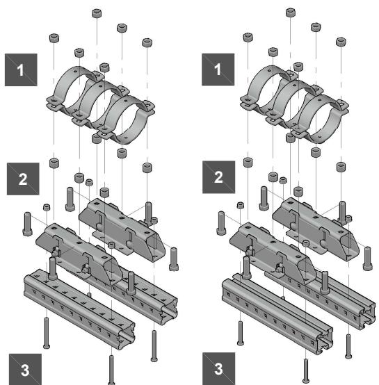
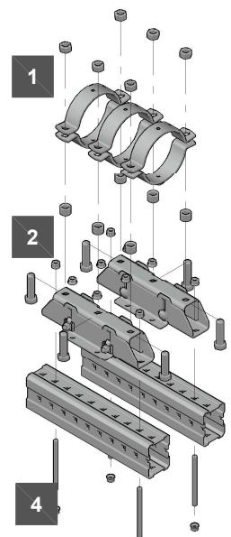
| Application description | Application | Product lines | Base material |
| Heating - MFP-CHD fixed point fixed on MI / MIQ structure | Fixed point sets | MI / MIQ System | |
| General comments | Threaded parts | ||
| • Application subject to thermal expansion impact, no seismic, no fatigue impact | |||
| • Loading and load impact must always be compared with 3D capacity limits for every single part of the application |
Fixed Point On MI / MIQ structure - MFP-CHD:
MFP-CHD without sound insulation
| 1 | Brackets MIC-C90-DH for concrete | |
| Bracket (Cantilever arm) | ||
| 1x | MIC-C90-DH-500 | 2203572 |
| MIC-C90-DH-750 | 2203573 | |
| MIC-C90-DH-1000 | 2203574 | |
| MIC-C90-DH-1500 | 2203575 | |
| MIC-C90-DH-2000 | 2203576 | |
| Anchors | ||
| 4x | HST3-R M16x135 35/15 | 2105876 |
| 2 | Connector MIQC-90-MIMIQ-90 fixed on MI-90 | |
| 1x | MIQC-90-MI | 2140257 |
| Connector includes all connecting hardware | ||
| 3 | Girders | |
| MIQ-90 | ||
| MIQ-90 3m girder | 2119866 | |
| MIQ-90 6m girder | 2119867 | |
| 4 | Fixation to on MIQ-90 girder | |
| 2x | MIQM-M16 wing nut | 2120276 |
| 2x | M16X30 hex. head screw | 2184501 |
| 5 | MFP-CHD Fixed point set | |
| 1x | MFP-CHD set | 2238264 |
| 6 | MFP-PC | |
| Fixed Point Pipe Ring | ||
| 3x | MFP-PC 73-78 M20 | 2227701 |
| MFP-PC 88-93 M20 | 2227702 | |
| MFP-PC 100-105 M20 | 2227703 | |
| MFP-PC 108-115 M20 | 2227704 | |
| MFP-PC 125-133 M20 | 2227705 | |
| MFP-PC 134-142 M20 | 2227706 | |
| MFP-PC 154-162 M20 | 2227707 | |
| MFP-PC 162-170 M20 | 2227708 | |
| MFP-PC 192-200 M20 | 2227709 | |
| MFP-PC 213-221 M20 | 2227710 | |
| 7 | Plastic end caps | |
| MIA-EC | 432077 | |
Assembled application

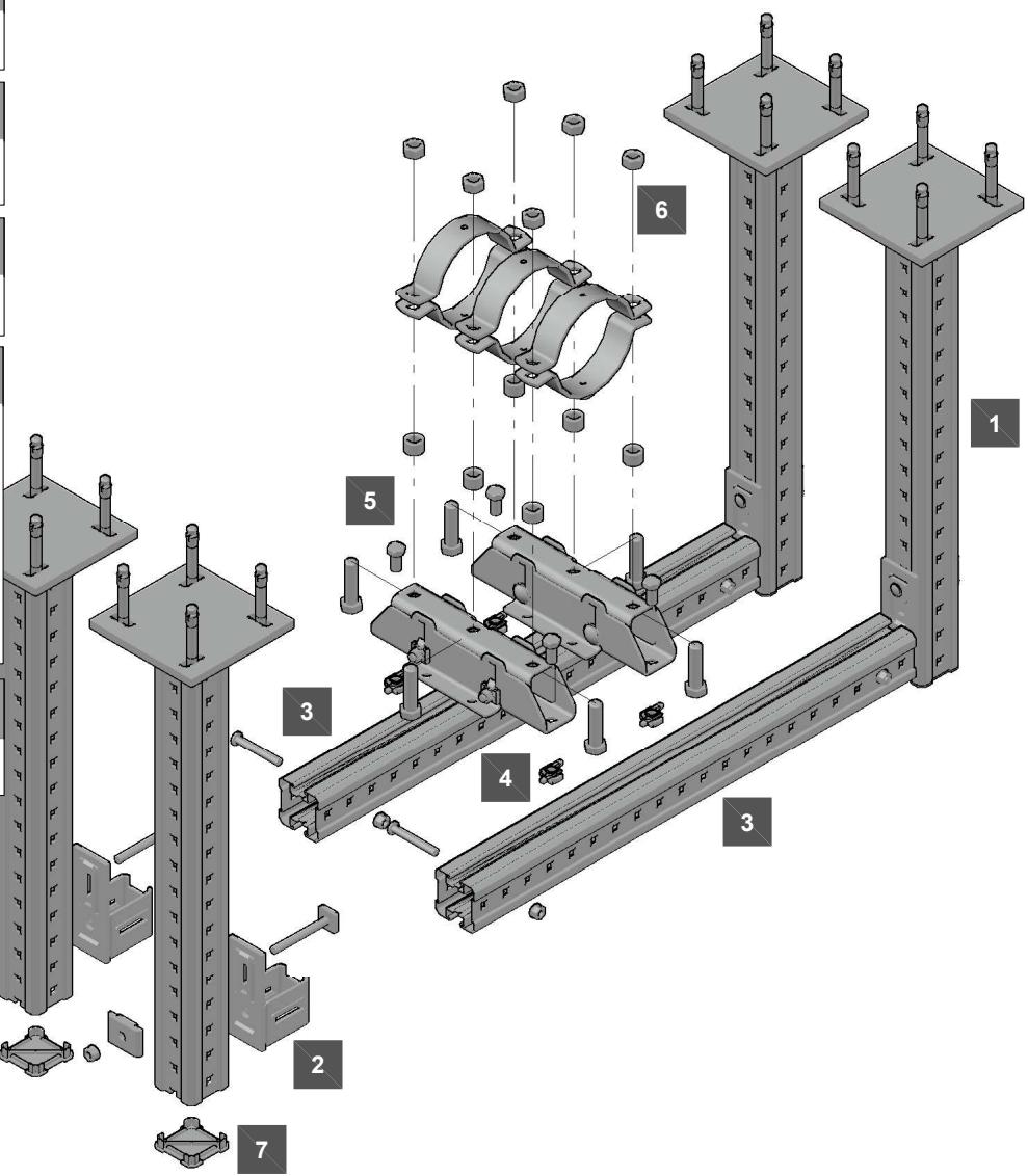
| Application description | Application | Product lines | Base material |
| Heating - MFP-CHD fixed point fixed on MI / MIQ structure | Fixed point sets | MI / MIQ System | |
| General comments | Threaded parts | ||
| • Application subject to thermal expansion impact, no seismic, no fatigue impact | |||
| • Loading and load impact must always be compared with 3D capacity limits for every single part of the application |
Fixed Point On Concrete - MFP-CSL with longer distance than Hmax :
MFP-CSL spec without sound insulation
1 | 1 | MFP-PCFixed Point Pipe Ring | |
| 1x | MFP-PC 21-22 M20 | 2227599 | |
| MFP-PC 25-27 M20 | 2227690 | ||
| MFP-PC 28-30 M20 | 2227691 | ||
| MFP-PC 31-33 M20 | 2227692 | ||
| MFP-PC 33.5-36 M20 | 2227693 | ||
| MFP-PC 39-41 M20 | 2227694 | ||
| MFP-PC 42-45 M20 | 2227695 | ||
| MFP-PC 47-50 M20 | 2227696 | ||
| MFP-PC 53-56 M20 | 2227697 | ||
| MFP-PC 57-61 M20 | 2227698 | ||
| MFP-PC 62-66 M20 | 2227699 | ||
| MFP-PC 68-72 M20 | 2227700 | ||
| MFP-PC 73-78 M20 | 2227701 | ||
| MFP-PC 88-93 M20 | 2227702 | ||
| MFP-PC 100-105 M20 | 2227703 | ||
| MFP-PC 108-115 M20 | 2227704 | ||
| 2 | AM20Threaded Rod | ||
| 1x AM20 x 1000 threaded rod | 216425 | ||
| 3 | MFP-CSLFixed point set | ||
| 1x MFP-CSL set | 2223016 | ||
| 4 | Anchors | ||
| 2x HUS3-H 10x90 35/15/5 or 2x HST3 M12x85 10/- | 2079914 2113978 | ||
| 2 | 2 | AM20Threaded Rod | ||
| 1x | AM20 x 1000 threaded rod | 216425 | ||
| 3 | 2 | MFP-CSLFixed point set | ||
| 1x | MFP-CSL set | 2223016 | ||
| 4 | 3 | Anchors | ||
| 2x | HUS3-H 10x90 35/15/5 | 2079914 | ||
| or | ||||
| 2x | HST3 M12x85 10/- | 2113978 | ||
Resistance and limitations
Hspec
height from base material to the center of the pipe
Recommended resistance
(safety factor 1.4 included):
Fspec = for loading capacity cases, see
the reverse page
Validity of the capacity limits:
- Temperature limits: see the chapter ,,Temperature influence,,
of this manual, - Published allowable loads for applications are based on static loading conditions.
Disclamier: - Load not applicable in any other than designated direction
- Load must be applied in the direction, that threaded rod is exposed
to tension (as pictured) - Any lateral load expose must be individually evaluated


| Application description | Application | Product lines | Base material |
| Heating - MFP-CSL spec. fixed point - longer distance | Fixed point sets | Concrete | |
| General comments | Threaded parts | ||
| • Application subject to thermal expansion impact, no seismic, no fatigue impact | |||
| • Loading and load impact must always be compared with 3D capacity limits for every single part of the application |

MFP-CSL with longer distance recommended loading capacity limits
| Hspec. [mm] | F [kN] |
| 125 | 2.000 |
| 130 | 1.923 |
| 140 | 1.786 |
| 150 | 1.667 |
| 160 | 1.563 |
| 170 | 1.471 |
| 180 | 1.389 |
| 190 | 1.316 |
| 200 | 1.250 |
| 210 | 1.190 |
| 220 | 1.136 |
| 230 | 1.087 |
| 240 | 1.042 |
| 250 | 1.000 |
| 260 | 0.962 |
| 270 | 0.926 |
| 280 | 0.893 |
| 290 | 0.862 |
| 300 | 0.833 |
Fixed Point On Concrete - MFP-CSL-I with longer distance than Hmax :
MFP-CSL-I with sound insulation
| 1 |  | 1 | MFP-PCFixed Point Pipe Ring | |
| 1x | MFP-PC 21-22 M20 | 2227599 | ||
| MFP-PC 25-27 M20 | 2227690 | |||
| MFP-PC 28-30 M20 | 2227691 | |||
| MFP-PC 31-33 M20 | 2227692 | |||
| MFP-PC 33.5-36 M20 | 2227693 | |||
| MFP-PC 39-41 M20 | 2227694 | |||
| MFP-PC 42-45 M20 | 2227695 | |||
| MFP-PC 47-50 M20 | 2227696 | |||
| MFP-PC 53-56 M20 | 2227697 | |||
| MFP-PC 57-61 M20 | 2227698 | |||
| MFP-PC 62-66 M20 | 2227699 | |||
| MFP-PC 68-72 M20 | 2227700 | |||
| MFP-PC 73-78 M20 | 2227701 | |||
| MFP-PC 88-93 M20 | 2227702 | |||
| MFP-PC 100-105 M20 | 2227703 | |||
| MFP-PC 108-115 M20 | 2227704 | |||
| 2 | 2 | AM20Threaded Rod | ||
| 1x | AM20 x 1000 threaded rod | 216425 | ||
| 2 | 2 | MFP-CSL-IFixed point set | ||
| 1x | MFP-CSL-I set | 2223017 | ||
| 3 | 3 | Anchors | ||
| 2x | HUS3-H 10x90 35/15/5 | 2079914 | ||
| or | ||||
| 2x | HST3 M12x85 10/- | 2113978 | ||
1
Resistance and limitations
Hspec
height from base material to the center of the pipe
Recommended resistance
(safety factor 1.4 included):
Fspec = for loading capacity cases, see
the reverse page
Validity of the capacity limits:
- Temperature limits: see the chapter ,,Temperature influence,,
of this manual,,
- Published allowable loads for applications are based on static
loading conditions.
Disclamier:
- Load not applicable in any other than designated direction
- Load must be applied in the direction, that threaded rod is exposed
to tension (as pictured)
- Any lateral load expose must be individually evaluated


Application description
Heating - MFP-CSL-I fixed point
General comments
- Application subject to thermal expansion impact, no seismic, no fatigue impact
- Loading and load impact must always be compared with 3D capacity limits for every single part of the application
Application

Product lines
Fixed point sets
Threaded parts
Base material
Concrete
[Non-Text]

MFP-CSL-I with longer distance recommended loading capacity limits
| Hspec. [mm] | F [kN] |
| 125 | 2.000 |
| 130 | 1.923 |
| 140 | 1.786 |
| 150 | 1.667 |
| 160 | 1.563 |
| 170 | 1.471 |
| 180 | 1.389 |
| 190 | 1.316 |
| 200 | 1.250 |
| 210 | 1.190 |
| 220 | 1.136 |
| 230 | 1.087 |
| 240 | 1.042 |
| 250 | 1.000 |
| 260 | 0.962 |
| 270 | 0.926 |
| 280 | 0.893 |
| 290 | 0.862 |
| 300 | 0.833 |
Fixed Point On Concrete - MFP-CL-I with longer distance than Hmax:
MFP-CL-I with sound insulation
1 | 1 | MFP-PCFixed Point Pipe Ring | |
| 2x | MFP-PC 21-22 M20 | 2227599 | |
| MFP-PC 25-27 M20 | 2227690 | ||
| MFP-PC 28-30 M20 | 2227691 | ||
| MFP-PC 31-33 M20 | 2227692 | ||
| MFP-PC 33.5-36 M20 | 2227693 | ||
| MFP-PC 39-41 M20 | 2227694 | ||
| MFP-PC 42-45 M20 | 2227695 | ||
| MFP-PC 47-50 M20 | 2227696 | ||
| MFP-PC 53-56 M20 | 2227697 | ||
| MFP-PC 57-61 M20 | 2227698 | ||
| MFP-PC 62-66 M20 | 2227699 | ||
| MFP-PC 68-72 M20 | 2227700 | ||
| MFP-PC 73-78 M20 | 2227701 | ||
| MFP-PC 88-93 M20 | 2227702 | ||
| MFP-PC 100-105 M20 | 2227703 | ||
| MFP-PC 108-115 M20 | 2227704 | ||
| MFP-PC 125-133 M20 | 2227705 | ||
| MFP-PC 134-142 M20 | 2227706 | ||
| MFP-PC 154-162 M20 | 2227707 | ||
| MFP-PC 162-170 M20 | 2227708 | ||
| 2 | AM20Threaded Rod | ||
| 2x AM20 x 1000 threaded rod | 216425 | ||
| 3 | MFP-CL-IFixed point set | ||
| 1x MFP-CL-I set | 2223018 | ||
| 4 | Anchors | ||
| 2x HUS3-H 10x60 5/-/-or | 2079911 | ||
| 2x HST3 M12x85 10/- | 2113978 | ||
| 2 | AM20 Threaded Rod | |
| 2x | AM20 x 1000 threaded rod 216425 | |
| 3 | 2 | MFP-CL-I Fixed point set |
| 1x | MFP-CL-I set 2223018 |
| 3 | Anchors | |
| 2x | HUS3-H 10x60 5/-/- | 2079911 |
| or | ||
| 2x | HST3 M12x85 10/- | 2113978 |
Alternative anchor points

Resistance and limitations
Hspec
height from base material to the center of the pipe
Recommended resistance
(safety factor 1.4 included):
Fspec = for loading capacity cases, see the reverse page
Validity of the capacity limits:
- Temperature limits: see the chapter ,,Temperature influence,,
of this manual,
- Published allowable loads for applications are based on static
loading conditions.
Disclamier:
- Load not applicable in any other than designated direction
- Load must be applied in the direction, that threaded rod is exposed
to tension (as pictured)
- Any lateral load expose must be individually evaluated


Application description
Heating - MFP-CL-I fixed point - longer distance
General comments
- Application subject to thermal expansion impact, no seismic, no fatigue impact
- Loading and load impact must always be compared with 3D capacity limits for every single part of the application
Application

Product lines
Fixed point sets
Threaded parts
Base material
Concrete
The Ground Truth image displays a single, solid horizontal line. According to Rule 2 (UNDERSCORE & LINE RULES), this is a stylistic or background line, not a placeholder underscore. Therefore, the OCR result must ignore it and output nothing or only meaningful text. The provided OCR content is "____", which consists of four underscores. This is an incorrect interpretation of the line as a placeholder, violating the rule that stylistic lines must be ignored. The OCR has hallucinated underscores where none should exist based on the GT's visual context. Hence, the OCR result is inconsistent with the Ground Truth.
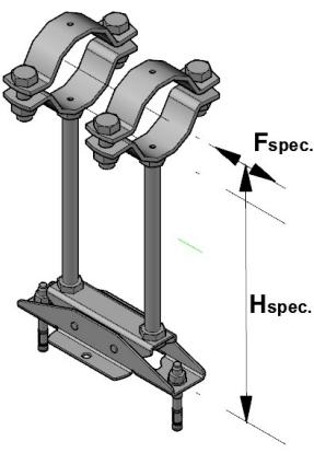
MFP-CL-I with longer distance recommended loading capacity limits
| Hspec. [mm] | F [kN] |
| 125 | 4.000 |
| 130 | 3.846 |
| 140 | 3.571 |
| 150 | 3.333 |
| 160 | 3.125 |
| 170 | 2.941 |
| 180 | 2.778 |
| 190 | 2.632 |
| 200 | 2.500 |
| 210 | 2.381 |
| 220 | 2.273 |
| 230 | 2.174 |
| 240 | 2.083 |
| 250 | 2.000 |
| 260 | 1.923 |
| 270 | 1.852 |
| 280 | 1.786 |
| 290 | 1.724 |
| 300 | 1.667 |
Fixed Point On Concrete - MFP-CLD-I with longer distance than Hmax: :
MFP-CL-I with sound insulation
| 1 | 1 | MFP-PCFixed Point Pipe Ring | |
 | 2x | MFP-PC 73-78 M20 2227701MFP-PC 88-93 M20 2227702MFP-PC 100-105 M20 2227703MFP-PC 108-115 M20 2227704MFP-PC 125-133 M20 2227705MFP-PC 134-142 M20 2227706MFP-PC 154-162 M20 2227707MFP-PC 162-170 M20 2227708MFP-PC 192-200 M20 2227709MFP-PC 213-221 M20 2227710 | |
| 2 | 2 | AM20Threaded Rod | |
 | 4x | AM20 x 1000 threaded rod 216425 | |
| 3 | 2 | MFP-CLD-IFixed point set | |
 | 1x | MFP-CLD-I set 2223014The 4x M20 bolts from the original packageremain unused | |
| 4 | 3 | Anchors | |
 | 4x | HUS3-H 10x60 5/-/- 2079911or | |
| 4x | HST3 M12x85 10/- 2113978 | ||
Resistance and limitations
Hspec
height above ground to the center the of pipe
Recommended resistance
(safety factor 1.4 included):
Fspec = for loading capacity cases, see the reverse page
Validity of the capacity limits:
- Temperature limits: see the chapter „Temperature influence,, of this manual...
- Published allowable loads for applications are based on static loading conditions.
Disclamier:
- Load not applicable in any other than designated direction
- Load must be applied in the direction, that threaded rod is exposed to tension (as pictured)
- Any lateral load expose must be individually evaluated


Alternative anchor points

Application description
Heating - MFP-CLD-I fixed point
General comments
- Application subject to thermal expansion impact, no seismic, no fatigue impact
- Loading and load impact must always be compared with 3D capacity limits for every single part of the application
Application

Product lines
Fixed point sets
Threaded parts
Base material
Concrete
[Non-Text]

MFP-CL-I with longer distance recommended loading capacity limits
| Hspec. [mm] | F [kN] |
| 125 | 8.000 |
| 130 | 7.692 |
| 140 | 7.143 |
| 150 | 6.667 |
| 160 | 6.250 |
| 170 | 5.882 |
| 180 | 5.556 |
| 190 | 5.263 |
| 200 | 5.000 |
| 210 | 4.762 |
| 220 | 4.545 |
| 230 | 4.348 |
| 240 | 4.167 |
| 250 | 4.000 |
| 260 | 3.846 |
| 270 | 3.704 |
| 280 | 3.571 |
| 290 | 3.448 |
| 300 | 3.333 |
PIPE CLAMPS LOADING CAPACITY

| Item number | Description | D (ø) | Fmax |
| 2227599 | MFP-PC M20 21-22 | 21-22 | 4kN |
| 2227690 | MFP-PC M20 25-27 | 25-27 | 4kN |
| 2227691 | MFP-PC M20 28-30 | 28-30 | 4kN |
| 2227692 | MFP-PC M20 31-33 | 31-33 | 4kN |
| 2227693 | MFP-PC M20 34-36 | 34-36 | 6.5kN |
| 2227694 | MFP-PC M20 39-41 | 39-41 | 6.5kN |
| 2227695 | MFP-PC M20 42-45 | 42-45 | 6.5kN |
| 2227696 | MFP-PC M20 47-50 | 47-50 | 6.5kN |
| 2227697 | MFP-PC M20 53-56 | 53-56 | 6.5kN |
| 2227698 | MFP-PC M20 57-61 | 57-61 | 8kN |
| 2227699 | MFP-PC M20 62-66 | 62-66 | 8kN |
| 2227700 | MFP-PC M20 68-72 | 68-72 | 8kN |

| Item number | Description | D (ø) | Fmax |
| 2227701 | MFP-PC M20 73-78 | 73-78 | 8kN |
| 2227702 | MFP-PC M20 88-93 | 88-93 | 8kN |
| 2227703 | MFP-PC M20 100-105 | 100-105 | 8kN |
| 2227704 | MFP-PC M20 108-115 | 108-115 | 8kN |
| 2227705 | MFP-PC M20 125-133 | 125-133 | 8kN |
| 2227706 | MFP-PC M20 134-142 | 134-142 | 8kN |
| 2227707 | MFP-PC M20 154-162 | 154-162 | 8kN |
| 2227708 | MFP-PC M20 162-170 | 162-170 | 8kN |
| 2227709 | MFP-PC M20 192-200 | 192-200 | 8kN |
| 2227710 | MFP-PC M20 213-221 | 213-221 | 8kN |
| 2227711 | MFP-PC M20 242-250 | 242-250 | 8kN |
| 2227712 | MFP-PC M20 267-275 | 267-275 | 8kN |
| 2227598 | MFP-PC M20 318-326 | 318-326 | 8kN |
KF FIXED POINTS OVERVIEW


| MFP-KF + MFP-UL / MFP-UL-I | |||
| # | Name | Fmax (N) | |
| 2238671 | MFP-KF | 76 | 2.000 |
| 2238672 | MFP-KF | 89 | 2.500 |
| 2238673 | MFP-KF | 114 | 3.000 |
| 2238674 | MFP-KF | 133 | 3.500 |
| 2238675 | MFP-KF | 140 | 3.500 |
| 2238676 | MFP-KF | 159 | 4.000 |
| 2238677 | MFP-KF | 168 | 4.000 |
| 2238678 | MFP-KF | 219 | 4.000 |
| 2238679 | MFP-KF | 273 | 4.000 |


| MFP-KF + MFP-UL2 / MFP-UL2-I | |||
| # | Name | Fmax (N) | |
| 2238671 | MFP-KF | 76 | 2.000 |
| 2238672 | MFP-KF | 89 | 2.500 |
| 2238673 | MFP-KF | 114 | 3.000 |
| 2238674 | MFP-KF | 133 | 3.500 |
| 2238675 | MFP-KF | 140 | 3.500 |
| 2238676 | MFP-KF | 159 | 4.000 |
| 2238677 | MFP-KF | 168 | 4.000 |
| 2238678 | MFP-KF | 219 | 4.000 |
| 2238679 | MFP-KF | 273 | 4.000 |


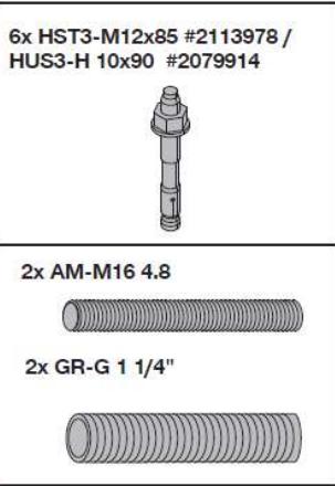
| MFP-KF + MFP-ULD / MFP-ULD-I | |||
| # | Name | Fmax (N) | |
| 2238678 | MFP-KF | 219 | 9.000 |
| 2238679 | MFP-KF | 273 | 12.000 |
| 2238680 | MFP-KF | 324 | 14.000 |
| 2238681 | MFP-KF | 356 | 14.000 |
| 2238682 | MFP-KF | 368 | 14.000 |
| 2238683 | MFP-KF | 406 | 14.000 |
| 2238684 | MFP-KF | 457 | 14.000 |
| 2238685 | MFP-KF | 508 | 14.000 |
| 2238670 | MFP-KF | 609 | 14.000 |


| MFP-KF + MFP-ULD2 / MFP-ULD24 | ||
| # | Name | Fmax (N) |
| 2238678 | MFP-KF 219 | 9.000 |
| 2238679 | MFP-KF 273 | 12.000 |
| 2238680 | MFP-KF 324 | 14.000 |
| 2238681 | MFP-KF 356 | 14.000 |
| 2238682 | MFP-KF 368 | 14.000 |
| 2238683 | MFP-KF 406 | 14.000 |
| 2238684 | MFP-KF 457 | 14.000 |
| 2238685 | MFP-KF 508 | 14.000 |
| 2238670 | MFP-KF 609 | 14.000 |
KF FIXED POINTS OVERVIEW

| 1x Set MFP-UHD# 2223138 | 4x HST3-M12 x 85# 2113978 /HUS3-H 10 x 90# 2079914 | 4x HST3-M16 x 135# 2105858 /HUS3-H 14 x 130# 2079923 | |
1x MFP-KF | 2x AM-M16 4.8 2x GR-G 1 1/4" 2x GR-G 1 1/4" | ||
| MFP-KF + MFP-UHD | |||
| # | Name | Fmax (N) | |
| 2238678 | MFP-KF | 219 | 9.000 |
| 2238679 | MFP-KF | 273 | 12.000 |
| 2238680 | MFP-KF | 324 | 14.500 |
| 2238681 | MFP-KF | 356 | 16.500 |
| 2238682 | MFP-KF | 368 | 16.500 |
| 2238683 | MFP-KF | 406 | 18.000 |
| 2238684 | MFP-KF | 457 | 18.000 |
| 2238685 | MFP-KF | 508 | 20.000 |
| 2238670 | MFP-KF | 609 | 20.000 |
KF 30/40
335218


| 1x Set MFP-UHD2# 2223140 | 4x HST3-M12 x 85# 2113978 /HUS3-H 10 x 90# 2079914[8KXW] | 8x HST3-M16 x 135# 2105858 /HUS3-H 14 x 13# 2079923[0KXW] | |
1x MFP-KF |  2x C 2x C  | ||
| MFP-KF + MFP-UHD2 | |||
| # | Name | Fmax (N) | |
| 2238678 | MFP-KF | 219 | 9.000 |
| 2238679 | MFP-KF | 273 | 12.000 |
| 2238680 | MFP-KF | 324 | 14.500 |
| 2238681 | MFP-KF | 356 | 16.500 |
| 2238682 | MFP-KF | 368 | 16.500 |
| 2238683 | MFP-KF | 406 | 18.000 |
| 2238684 | MFP-KF | 457 | 18.000 |
| 2238685 | MFP-KF | 508 | 20.000 |
| 2238670 | MFP-KF | 609 | 20.000 |
KF 30/40
335218

Temperature influence on NON-SOUND insulated fixed points
Stress impact (ref. Eurocode 3):
For intermediate values – please use linear interpolation
100°C – reduction factor 1.00
200°C – reduction factor 1.00
300°C – reduction factor 1.00
400°C – reduction factor 1.02
500°C – reduction factor 1.19
600°C – reduction factor 2.30
600°C – Eurocode 3 not applicable please refer to following chapter ,,Fixed Points – Fire Resistance Loading Capacity,,
Serviceability impact (ref. Eurocode 3):
For intermediate values – please use linear interpolation
100°C - deformation factor 1.00
200°C - deformation factor 1.10
300°C - deformation factor 1.25
400°C - deformation factor 1.43
500°C - deformation factor 1.67
600°C - deformation factor 3.23
600°C – Eurocode 3 not applicable please refer to following chapter ,,Fixed Points – Fire Resistance Loading Capacity,,
Constant elevated temperature will lead to tarnish colors on the galvanized surface. This starts at about 120° C on electro-galvanized surfaces and at about 250° C on hot-dip galvanized products.
This statement is based on external assessment, Eurocode 3 specification and more than 20 years experience of Hilti selling installation channel systems parts worldwide.
This confirmation regarding the maximal working temperature for Hilti installation products which do not include any non-steel components does not constitute any warranty.
Temperature influence on SOUND insulated fixed points
Hilti Fixed Points use EPDM as material for the sound insulation component.
EPDM temperature resistance - max 120°C long-term exposure
- short-term moderate increase (up to 10 hours) can be accepted.
Temperature increases beyond 10 hours will not affect the load capacity of the sound insulating component. An accelerated aging of the material, depending on the level of the temperature, is expected. This causes a premature hardening and embrittlement, which ultimately leads to significant deterioration of the sound insulation properties of the material.
This statement is based on external assessment, manufacturers data and more than 30 years' experience of Hilti selling installation system parts worldwide.
This confirmation regarding the maximal recommended working temperature for Hilti installation products with sound insulation component does not constitute any warranty.
FIXED POINTS - FIRE RESISTANCE LOADING CAPACITY
For temperatures > 600°C
Studies made by MFPA Leipzig GmbH (Germany) showed that thin wall profiles exposed to temperatures above 600°C behave differently (and more critical especially regarding deformation) than predicted by Eurocode EC3-1-2 fire resistance design approach and expressed invalidity of the EC3-1-2 for these cases.
This statement was followed by investigations and series of tests to find optimal evaluation of these cases. It resulted in harmonized design method
EAD 280016-00-0602 from February 2018
PRODUCTS RELATED TO INSTALLATION SYSTEMS SUPPORTING TECHNICAL EQUIPMENT FOR BUILDING SERVICES SUCH AS PIPES, CONDUITS, DUCTS AND CABLES
However the EAD is not covering fixed point applications, but lessons learned from ETA approvals were used and considered defining the loading capacity limits of the fixed points under fire. The temperature curve used for the loading capacity limits refer to EN 1363
Standard Fire Test Heating Curve


Fire resistance values covering gravity support function of the Fixed Point only
FRk,x

MFP-CL-I

MFP-CLD-I

MFP-UM

MFP-UM2

MFP-UHD

MFP-UHD2
| for sizes 21-326 | for sizes 73-326 | for sizes 73-326 | for sizes 73-326 | for sizes 73-326 | for sizes 73-326 | |
| F30 | 4.3 | 5.0 | 5.0 | 5.0 | 5.0 | 5.0 |
| F60 | 2.1 | 3.2 | 3.2 | 3.2 | 3.2 | 3.2 |
| F90 | 1.4 | 2.6 | 2.6 | 2.6 | 2.6 | 2.6 |
| F120 | 1.0 | 2.3 | 2.3 | 2.3 | 2.3 | 2.3 |
- FIXED POINTS
- TERMS OF COMMON COOPERATION / LEGAL DISCLAIMER
- FIXED POINT - TECHNICAL BACKGROUND INFORMATION
- TECHNICAL CHALLENGES AND HOW THESE DICTATE THE PRODUCT REQUIREMENTS
- EXPANSION MUST BE CONTROLLED
- UNCONTROLLED EXPANSION – IMPACT ON SUPPORTS AND SURROUNDINGS
- CONTROLLING EXPANSION – METHODS USED TO CONTROL EXPANSION
- FIXED POINTS – PLACEMENT - EMPIRICAL RULE
- FIXED POINTS – LOADS
- HILTI FIXED POINT LOAD TRANSFER PRINCIPLES
- FIXED POINT VERSUS LOADING CAPACITY OF THE STRUCTURE
- FIXED POINT ON CONCRETE - MFP-CSL FIXED POINT
- RESISTANCE AND LIMITATIONS
- APPLICATION DESCRIPTION
- GENERAL COMMENTS
- APPLICATION
- PRODUCT LINES
- BASE MATERIAL
- FIXED POINT ON CONCRETE - MFP-CSL-I FIXED POINT
- FIXED POINT ON CONCRETE - MFP-CL-I FIXED POINT
- RECOMMENDED RESISTANCE
- FIXED POINT ON CONCRETE - MFP-CLD-I FIXED POINT
- FIXED POINT ON CONCRETE - MFP-CH FIXED POINT
- FIXED POINT ON CONCRETE - MFP-CH (M12) USING ALTERNATIVE ANCHORING
- FIXED POINT ON CONCRETE - MFP-CHD FIXED POINT
- FIXED POINT ON CONCRETE - MFP-CHD FIXED POINT (M12) FIXED POINT USING ALTERNATIVE ANCHORING
- FIXED POINT ON CONCRETE - MFP-L FIXED POINT
- MFP-L RECOMMENDED LOADING CAPACITY LIMITS
- FIXED POINT ON CONCRETE - MFP-L2 FIXED POINT
- MFP-L2 FIXED POINT SET
- M20 BASE THREADED ROD
- M16 BRACING THREADED ROD
- ANCHORS
- HEATING - MFP-L2 FIXED POINT
- FIXED POINT ON CONCRETE - MFP-LD FIXED POINT
- FIXED POINT ON CONCRETE - MFP-LD2 FIXED POINT
- FIXED POINT ON CONCRETE - MFP-L-I FIXED POINT
- MFP-L-I FIXED POINT SET
- MFP-L-I RECOMMENDED LOADING CAPACITY LIMITS
- FIXED POINT ON CONCRETE - MFP-L2-I FIXED POINT
- FIXED POINT ON CONCRETE - MFP-LD-I FIXED POINT
- FIXED POINT ON CONCRETE - MFP-LD2-I FIXED POINT
- MFP-PC
- FIXED POINT PIPE RING
- MFP-LD2-IFIXED POINT SET
- FIXED POINT ON CONCRETE - MFP-UL FIXED POINT
- MFP-UL RECOMMENDED LOADING CAPACITY LIMITS
- FIXED POINT ON CONCRETE - MFP-UL2 FIXED POINT
- MFP-UL2 FIXED POINT SET
- ¼" THREADED TUBE
- HEATING - MFP-UL2 FIXED POINT
- MFP-UL2 RECOMMENDED LOADING CAPACITY LIMITS
- FIXED POINT ON CONCRETE - MFP-ULD FIXED POINT
- MFP-ULD FIXED POINT SET
- THREADED TUBE
- FIXED POINT ON CONCRETE - MFP-ULD2 FIXED POINT
- MFP-ULD2 RECOMMENDED LOADING CAPACITY LIMITS
- FIXED POINT ON CONCRETE - MFP - UM FIXED POINT
- MFP-UM RECOMMENDED LOADING CAPACITY LIMITS
- FIXED POINT ON CONCRETE - MFP - UM2 FIXED POINT
- FIXED POINT ON CONCRETE - MFP-UHD FIXED POINT
- MFP-UHD FIXED POINT SET
- MFP-UHD RECOMMENDED LOADING CAPACITY LIMITS
- FIXED POINT ON CONCRETE - MFP-UHD2 FIXED POINT
- MFP-UHD2 RECOMMENDED LOADING CAPACITY LIMITS
- FIXED POINT ON CONCRETE - MFP-UL-I FIXED POINT
- MFP-UL-I RECOMMENDED LOADING CAPACITY LIMITS
- FIXED POINT ON CONCRETE - MFP-UL2-I FIXED POINT
- MFP-UL2-I FIXED POINT SET
- MFP-UL2-I RECOMMENDED LOADING CAPACITY LIMITS
- FIXED POINT ON CONCRETE - MFP-ULD-I FIXED POINT
- FIXED POINT ON CONCRETE - MFP-ULD2-I FIXED POINT
- MFP-ULD2-I FIXED POINT SET
- FIXED POINT ON CONCRETE - MFP - UM - I FIXED POINT
- MFP-UM-I RECOMMENDED LOADING CAPACITY LIMITS
- FIXED POINT ON CONCRETE - MFP - UM2 - I FIXED POINT
- FIXED POINT ON CONCRETE - MFP-CL-I FIXATION ON CONCRETE COLUMN
- FIXED POINT ON MI/MIQ STRUCTURE - MFP-CL-I
- FIXED POINT ON MI/MIQ STRUCTURE - MFP-CLD-I
- FIXED POINT FIXED ON MI/MIQ SYSTEM STRUCTURE - MFP-CH
- FIXED POINT ON MI / MIQ STRUCTURE - MFP-CHD
- FIXED POINT ON CONCRETE - MFP-CSL WITH LONGER DISTANCE THAN HMAX
- HSPEC
- FSPEC = FOR LOADING CAPACITY CASES, SEE
- MFP-CSL WITH LONGER DISTANCE RECOMMENDED LOADING CAPACITY LIMITS
- FIXED POINT ON CONCRETE - MFP-CSL-I WITH LONGER DISTANCE THAN HMAX
- MFP-CSL-I WITH LONGER DISTANCE RECOMMENDED LOADING CAPACITY LIMITS
- FIXED POINT ON CONCRETE - MFP-CL-I WITH LONGER DISTANCE THAN HMAX
- FSPEC = FOR LOADING CAPACITY CASES, SEE THE REVERSE PAGE
- MFP-CL-I WITH LONGER DISTANCE RECOMMENDED LOADING CAPACITY LIMITS
- FIXED POINT ON CONCRETE - MFP-CLD-I WITH LONGER DISTANCE THAN HMAX
- PIPE CLAMPS LOADING CAPACITY
- KF FIXED POINTS OVERVIEW
- TEMPERATURE INFLUENCE ON NON-SOUND INSULATED FIXED POINTS
- TEMPERATURE INFLUENCE ON SOUND INSULATED FIXED POINTS
- FIXED POINTS - FIRE RESISTANCE LOADING CAPACITY
- FOR TEMPERATURES > 600°C
Brand : HILTI
Model : Fixed Points