
VG232232 - Gas stove GAGGENAU - Free user manual and instructions
Find the device manual for free VG232232 GAGGENAU in PDF.
| Product Type | Built-in gas hob |
| Brand | GAGGENAU |
| Model | VG232232 |
| Number of burners | 2 |
| Normal burner power (A) | 1.9 kW |
| High intensity burner power (B) | 2.8 kW |
| Electrical supply | 220-240 V ~ 50/60 Hz |
| Gas supply | Connection R 1/2" according to DIN 1999 |
| Ignition | Automatic spark ignition |
| Safety | Safety thermocouple device on each burner |
| Flame adjustment | Continuous from minimum to maximum position |
| Dimensions (W x D x H) | 288 x 520 x 90 mm (estimated) |
| Weight | Approximately 10 kg |
| Material | Stainless steel |
| Included accessories | Support grates, burner caps, burner heads |
| Optional accessories | Cover VD 201-010, connection bar VV 200-000 |
| Cleaning | Clean with a mild detergent and a soft cloth; do not use a steam cleaner |
| Repairability | Repairs exclusively by an authorized technician |
| Gas conversion | Possible by changing nozzles (kit available) |
Frequently Asked Questions - VG232232 GAGGENAU
User questions about VG232232 GAGGENAU
0 question about this device. Answer the ones you know or ask your own.
Ask a new question about this device
Download the instructions for your Gas stove in PDF format for free! Find your manual VG232232 - GAGGENAU and take your electronic device back in hand. On this page are published all the documents necessary for the use of your device. VG232232 by GAGGENAU.
USER MANUAL VG232232 GAGGENAU
Operating and assembly instructions
VG 232
Gas cooker
Preface
- Important notes Page 3-4
1.1 For your safety Page 3
1.2 Operating for the first time
1.3 About use Page 4
- Structure and operating principle Page 5-6
2.1 Structure
2.2 Special accessories
2.3 Operating principle Page 6 - Operation Page 7
- Cleaning and care Page 8
- Maintenance Page 9
5.1 General
5.2 Remedying slight malfunctions yourself Page 9 - Technical data / Settings table Page 10-11
- Assembly instructions Page 12-16
7.1 Important notes Page 12
7.2 Gas connection/electrical connection Page 13
7.3 Nozzle replacement Page 14-15
7.4 Installation Page 16
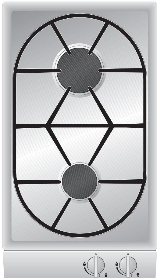
Fig. 1
Cooking with your new gas cooker will be even more fun than before.
The appliance offers you the following advantages:
- Regulation from hot to cold in seconds.
High safety standard thanks to thermal protection elements for all burners. - Thanks to the novel installation method implemented, installation is child's play!
To ensure that you will be able to use this appliance in all its diversity, read through the operating and assembly instructions conscientiously before operating it for the first time. The instructions contain important notes on use, installation and maintenance of the appliance.
You will find notes on page 3 that you ought to observe before operating the appliance for the first time.
The chapters entitled "Structure and operating principle" and "Operation" tell you all the things your cooker is capable of doing and how to operate the appliance.
The chapter entitled "Cleaning and care" will make sure that your appliance will stay operable and beautiful for a long time.
And now we wish you lots of fun cooking.
1. Important notes
1.1 For your safety
You must not operate the appliance if it is damaged. When connecting electrical appliances in the proximity of the appliance, make sure that connecting leads do not come into contact with hot cooking surfaces!
As the user, you yourself are responsible for maintenance and proper use in the household.
Only ever operate the appliance under supervision.
Do not operate the appliance without pots and pans placed on it. Make sure that all the burner parts are correctly fitted.
Important: The appliance heats up during operation. Keep children away.
Note:
If you have fitted the appliance cover VD 201-010 (special accessory) on the appliance, it must not be closed until the appliance has cooled down completely. Do not operate the appliance with the cover closed! Heat development may damage the appliance and the cover. Do not use the appliance cover as a surface for placing objects or for keeping things warm.
Do not clean the appliance with a steam cleaning apparatus or with water pressure - risk of short-circuits!
Isolate the appliance from the mains during every maintenance operation. To do this, remove the mains plug or actuate the corresponding fuse. Close the gas supply.
Repairs must be carried out by authorised specialists, thus ensuring electrical safety.
No warranty claims can be lodged for any damage resulting from failure to observe these instructions.
Observe caution with oils and fats. They may overheat and burn easily.
Foodstuffs that are prepared in fat and oil must only be prepared under constant supervision!
Technical modifications reserved.
1.2 Operating for the first time
Before operating the appliance for the first time, please pay attention to the following notes:
The appliance must only be connected by an authorised specialist.
Read through these instructions attentively before operating the appliance for the first time.
Note:
The rating plate for this appliance is included on a separate sheet. Keep the rating plate in a safe place along with your operating and assembly instructions.
Remove the packaging from the appliance and dispose of it properly.
Keep packaging elements away from children.
Thoroughly clean the appliance and accessories before using them for the first time. This will eliminate any "newness" smells and soiling (see chapter entitled "Cleaning and care").
1.3 About use
The appliance is intended solely for use in the household and must not be put to any other uses.
Use the appliance to prepare meals only. It must not be used to heat up the room in which it is installed.
Use of a gas cooker generates heat and humidity in the room where it is installed. This is why attention must be paid to good kitchen ventilation. The natural ventilation openings must be kept unobstructed. Prolonged use of the appliance with several or all rings may call for additional ventilation such as opening a window or a door, or stronger air extraction by an extractor hood.
To guarantee good combustion, the room in which the appliance is installed must have a minimum volume of 10m^3 and must possess a door that opens outdoors or a window that can be opened.
Only ever use the burners after placing pots and pans on them. Do not heat up any empty pots or pans; this may result in a build-up of heat. Use pots and pans with thicker bottoms because heat distribution is particularly improved in the low setting. The better the size of pots and pans is adapted to the burner size, the better the heat of the gas flame will be exploited and the more costs will be saved.
Cooking vessels with curved bottoms, e.g. woks, must not be used.
It is not permitted to use roasting pans, frying pans or grill stones heated simultaneously by several burners because the resulting heat build-up may damage the appliance.
Switch the burners to the low setting whenever you remove pots or pans briefly. In this way, you reduce the risk of burns when working next to naked flames; you also save gas and reduce pollution.
Whenever the gas hob is fitted under a vapour extractor hood, always cover the rings with pots or pans. Otherwise, parts of the vapour extractor hood may become damaged by the extreme heat development or grease residues in the filter may ignite. Ensure an adequate supply of air when using a vapour extractor operating in the exhaust air mode.
After igniting, keep the control knob pressed for around 5-8 seconds more because the heat sensor that opens the gas channel has to warm up first.
In the event of a power failure, you can also ignite the unit with matches or any other ignition aid. The thermal protection facility that prevent gas from flowing out in the open position functions without restriction.
Pots with a diameter of less than 90 ~mm or more than 220 ~mm should not be used. When using larger pots, pay attention to keeping to a minimum distance of 50 ~mm between the cooking vessel and combustible surroundings. A minimum distance of 15 ~mm must be observed between the control knob and the pot or pan.
In the event of malfunctions, contact your specialist dealer or your responsible Gaggenau after-sales service.
Tip: When buying pots, pay attention to the fact that the manufacturer frequently specifies the top pot diameter, which is generally larger than the diameter of the base.
Observe the manufacturer's specification! Use cooking utensils that the manufacturer states as being "suitable for gas".
Preferably use the larger cooking zone for brief cooking, deep fat frying and brief frying of large quantities. Preferably use the smaller ring for soaking, warming up and keeping warm, even when large quantities are involved.
2. Structure and operating principle
2.1 Structure
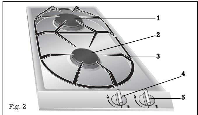
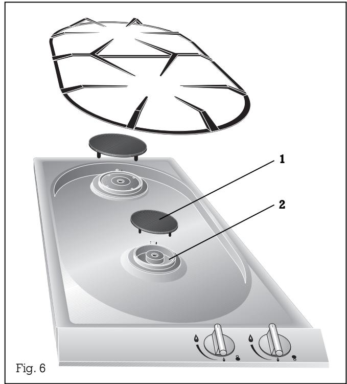
1 High-power burner B 2.8 kW
2 Normal burner A 1.9 kW
3 Pot support
4 Control knob for the front cooking position
5 Control knob for the rear cooking position
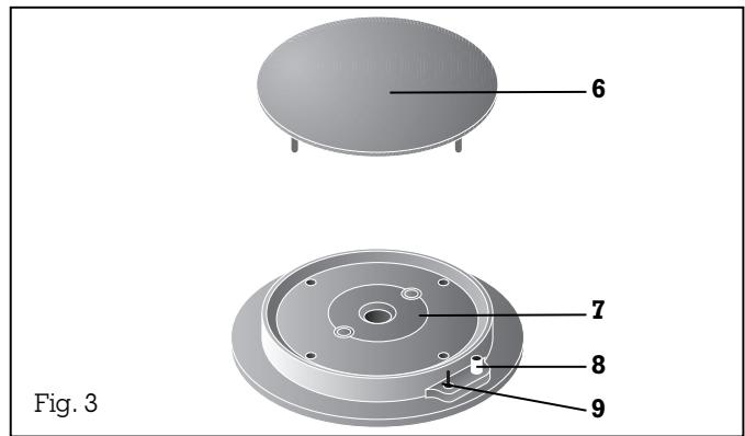
6 Burner cover
7 Burner head
8 Spark plug for automatic ignition
9 Thermal sensor for flame monitor
2.2 Special accessories
You can order the following special accessories:
- VV 200-000: Connecting strip
- VD 201-010: Appliance cover (If an appliance cover is fitted, the pot support must be removed when closing.)
2.3 Operating principle
The appliance features one-hand operation. That is to say, the ignition is activated when the control knob is pressed briefly.
After igniting, keep the control knob pressed for around 5-8 seconds more because the heat sensor that opens the gas channel has to warm up first.
The gas hob has 1 normal burner (front burner) and 1 high-intensity burner (rear burner).
All burners have a thermal protection device that prevents unburned gas from escaping in the open position.
The total rated thermal load amounts to:
4.7 kW referred to H_S^* (gross calorific value)
4.2 kW referred to H_j (calorific value)
The specified rated load is defined by installation of the fixed nozzles.
The gas hob is converted to a different gas
type by nozzle replacement (full and low-burning nozzles) (see nozzle table on pp. 10-11).
The symbols on the control panel mean:
0 Off
High setting
Low setting
The flame is infinitely variable between high and low-setting.
The cooking positions must only be ignited when all burner parts are fitted. Otherwise, malfunctions may occur on the ignition unit.
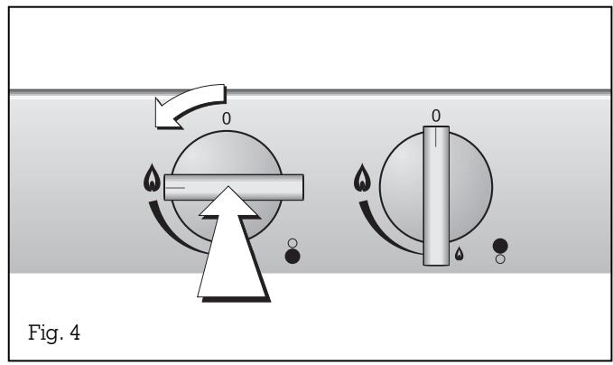
Switching on:
- Place a pot or a pan on the corresponding cooking position.
- Fully press in the control knob for the corresponding cooking position. This activates the ignition. Keep the control knob pressed!
- Turn the control knob to the left to the "high" position.
If the flame should not ignite within 2 to 4 seconds, turn the control knob further to the left to the "low" position and then back to the "high" position after ignition. It is often faster to ignite in the low position because the various gases have a differing ignition response.
After igniting, keep the control knob pressed for around 5-8 seconds more because the heat sensor that opens the gas channel has to warm up first.
Repeat the operation if the flame should go out again.
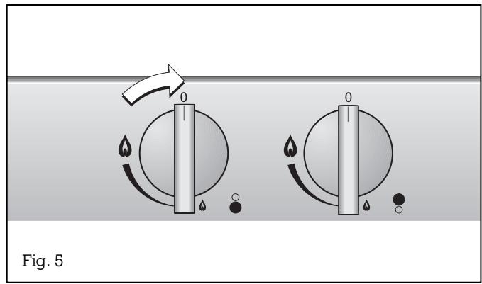
The flame size can be set continuously between full and low by slowing turning the control knob.
Switching off:
Fully turn the control knob to the left to the 0 position on the left.
4. Cleaning and care
Wipe off spilt food immediately, thus ensuring that it cannot burn in on the hob.
Caution! The burner gets very hot during operation!
Never use abrasive or caustic cleaning agents.
You should only clean the control panel and the control knobs with detergent and a soft cloth.
To ensure perfect functioning, keep the thermal sensor and the spark plug clean.
Keep the incoming air openings on the rear of the panel unobstructed and clean.
Please thoroughly clean the appliance before operating it for the first time and after every use.
- Wait until the appliance has cooled down.
- Remove the pot grid.
- Remove the burner cover.
- Clean the hob, the burner covers and the pot grid with commercially available cleaning agents (not in a dishwasher!), e.g. with warm soap solution and a dishwashing brush.
- Whenever required, clean the burner head with a moist cloth.
- Soak burnt-in remainders in a little water and detergent. This loosens even the most stubborn of soiling. Do not use any abrasive agents and abrasive sponges.
- As the result of heat development, slight discoloration can appear on the stainless steel surface. Do not attempt to scrape away such discoloration. This damages the surface.
Distribute stainless steel care agents uniformly and thinly on the hob (not on the control panel!). This will ensure an even surface and will keep your hob in a good condition for a long period of time.
Important: Allow the burner covers to cool down before cleaning them!
When assembling, place the burner cover (1) on the burner head (2) so that the four tabs on the bottom edge of the burner cover engage in the corresponding tabs on the burner head (see Fig. 6). Place the pot grids back in position.
Caution:
Never use high-pressure or steam jet units to clean your appliance because otherwise the electrical safety of the appliance will no longer be guaranteed.
5.1 General
In the event of malfunctions, check whether the gas and electricity supply is in proper working order, i.e. the gas valve is open and the plug has been plugged into the socket.
If the power supply is functioning correctly, but your appliance still does not work, please contact your dealer or your local Gaggenau customer service agency. Specify the appliance type (see rating plate).
Repairs may only be carried out by authorised technicians, in order to guarantee the safety of the appliance.
Unauthorized tampering with the appliance will invalidate any warranty claims.
Only ever use original spare parts.
5.2 Remedying slight malfunctions yourself
| Fault | Remedy |
| The burner does not ignite after several attempts. | Check whether ... ... the burner is correctly assembled. ... the gas shut-off facility is open. ... the burner is clean and dry. ... the domestic fuse has tripped. If necessary, inform after-sales service. |
| The gas flame goes off after ignition. | Check whether ... ... the burner covers are fitted correctly, ... the flame has been extinguished by a strong draught in the room. |
| The cooking ring burner's electrical igniter is no longer functioning. | Check whether there are food remainders between the ignition electrode and the burner cover. Carefully remove these. |
| The flame tips are yellow and not blue. | Check whether the burners are dry and clean. |
6. Technical data / Settings table
Technical data (gas)
Burners: Normal burner
Full burning 1.9 kW
Low burning < 0.35kW
High-intensity burner
Full burning 2.8 kW
Low burning < 0.56 kW
Technical data (electrical)
Rated consumption 0.8 W
Voltage 220-240V
Frequency 50 - 60 Hz
Technical modifications reserved.
Gas connection:
R 1/2" union nut for R 1/2" bracket to DIN 1999, conical-cylindrical
Technical data, gas
| Countries | DK ES IT SE | SE | FR | ES |
| Gas family | Town gas | Town gas | Town gas | Town gas |
| Gas type | a | b | c | e |
| Pressure | 8 mbar | 8 mbar | 8 mbar | 8 mbar |
| A burner, full burning | 2.20 | 1.95 | 2.20 | 2.20 |
| A burner, low burning | 0.47 gap* | 0.47 gap* | 0.47 gap* | 0.47 gap* |
| B burner, full burning | 3.00 | 2.60 | 3.00 | 3.00 |
| B burner, low burning | 0.55 gap** | 0.55 gap** | 0.55 gap** | 0.55 gap** |
| Σ Power | 4.45 kW | 4.45 kW | 4.45 kW | 4.45 kW |
| Σ Consumption | 1 m3/h | 0.95 m3/h | 0.6 m3/h | 0.8 m3/h |
$$ \begin{array}{r l r l r l} \star & = ^ {1 / 2} \oslash & & \star \star & = ^ {3 / 4} \oslash \end{array} $$
Technical data, gas
| Countries | AT BE CH DE DK ES FI FR GB GR IE IS IT LU NL PT SE | BE FR LU NL | DE | BE CH DK ES FI FR GB GR IE IS IT LU NL NO PT SE | AT DE |
| Gas family | Natural gas | Natural gas | Natural gas | But/Prop | But/Prop |
| Gas type | H/E (G 20) | L (G 25) | LL (G 25) | 3 + (G30/31) | (G30/31) |
| Pressure | 20 mbar | 25 mbar | 20 mbar | 28-30/37 mbar | 50 mbar |
| A burner, full burning | 0.92 | 0.92 | 1.04 | 0.68 | 0.59 |
| A burner, low burning | 0.47 | 0.47 | 0.51 | 0.30 | 0.26 |
| B burner, full burning | 1.24 | 1.24 | 1.40 | 0.85 | 0.72 |
| B burner, low burning | 0.55 | 0.55 | 0.61 | 0.36 | 0.32 |
| Σ Power | 4.7 kW | 4.7 kW | 4.7 kW | 4.7 kW | 4.7 kW |
| Σ Consumption | 0.45 m3/h | 0.45 m3/h | 0.5 m3/h | 340 g/h | 340 g/h |
7.1 Important notes
Please observe the safety notes and the important notes (Chapter 1).
The installing technician is responsible for perfect functioning of the appliance at its installation location.
He must explain the operating principle to the user with reference to the operating instructions and must show how to switch of the electricity and gas whenever required.
Caution:
Before connecting the appliance, please check whether the local connection conditions such as the gas type, gas pressure and mains voltage and the appliance settings are correct. Refer to the adhesive label on the gas connection or the rating plate for the necessary information. This gas hob conforms to the categories that are specified on the rating plate. The rating plate can be found on the appliance and additionally on the enclosed addendum sheet. By replacing nozzles, it is possible to set the appliance to any gas listed on the rating plate.
If the data should not agree, the appliance must be set to the required gas type and the available pressure.
As this gas hob is not intended for connection to an exhaust gas system, pay attention to the applicable installation conditions.
Note on ventilation:
To ensure good combustion, the room in which this appliance is installed must have a minimum volume of 10m^3 and a door that opens out to outdoors or a window that can be opened.
| VG 232-… | FDxxxxx | ||
| AC 220-240V | 50/60Hz | Σ Qn | 4.7 kW |
| 0.8 VA |
In Germany, the gas hob must be installed and connected by a fitter who has been approved by the gas supply company. At the same time, the guidelines such as DVGW-TRGI 86 and TRF 1988 and the regulations of the gas supply companies and of the responsible authorities must be observed.
In Switzerland, the respectively applicable regulations of SVGW and of the Association of Cantonal Fire Insurance Companies as well as the manufacturer's installation conditions must be observed when installing the appliance.
In Austria, the ÖVGW-TR Gas (G1) and ÖVGW-TR Flüssiggas (G2-Part 1) regulations and the local construction and trade regulations must be observed when installing the appliance.
The appliance may be installed in kitchen combinations made of wood or similar combustible materials without taking additional measures. The rear wall must consist of non-combustible material.
A minimum distance of 150mm from heat-sensitive items of furnishing or contact surfaces (cupboard side panel) must be observed.
The hob conforms to appliance class 3 and must be installed in the worktop as shown in the installation sketch.
The distance between the suspended cupboard and the worktop must be at least 600 ~mm .
Attention must be paid to the manufacturer's specified safety clearance when a vapour extractor is installed.
Wall trims must be heat-resistant, and the minimum distance between the hob and the wall trim is at least 35 ~mm .
After unpacking, check the appliance for any transportation damage and report this immediately to the transportation company.
Technical modifications reserved.
7.2 Connecting the appliance
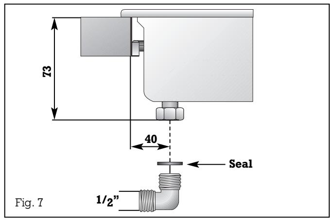
Gas connection
The gas connection must be in a location that permits access to the shut-off valve and which, if applicable, is visible after opening the door of the furniture item.
By means of the included R 1/2" connection bracket (on the appliance end) with the affiliated washer, the appliance must be connected to a fixed connecting line or a gas safety hose to DIN 3383 Part 1 that corresponds to the type concerned.
An ambient temperature of 70~K must not be exceeded if the gas safety consists only partly of metal. The permissible ambient temperature for a gas safety hose that consists completely of metal is 115~K .
If a flexible line is used, it must be laid in such a way that it cannot come into contact with moving parts of the kitchen element (e.g. drawer).
Electrical connection
Electrical connection (AC 220-240 V) is established by means of a connecting cable with an earthing contact plug connected to an earthed socket, which must also be accessible after installation of the gas hob.
If, after installation of the gas hob, not all poles can be isolated from the mains by removing the plug, an isolating device with a contact gap of at least 3mm must be permanently installed. When establishing connections, make sure that the connecting lead cannot come into contact with hot parts of the gas hob or other hot parts.
7.3 Nozzle replacement
See table on Pages 10 - 11 for details of nozzle settings.
Changing over to a different gas type
Only authorised specialists are permitted to change over to a different gas type.
The nozzles needed for the gas type to be set are available as a conversion kit. Please specify the appliance type and the required gas type.
Nozzles can be replaced without having to open the housing.
Loads for all gases
For all gas types and pressures, the rated load is achieved by installing the high and low setting nozzles for the required gas type (see nozzle table).
The low setting nozzle is screwed in fully at the works, and so the lowest quantity is set.
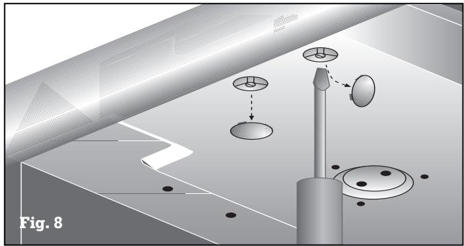
Replacing the low-setting nozzle 1
Proceed as follows:
- Disconnect the appliance from the power supply!
- Remove the cover from the underside of the appliance under the gas valves.
The low-setting nozzle 1 is located in the gas valve and is screwed in from below. (see Fig. 8)
- Unscrew the nozzle and insert the new nozzle as specified in the low-setting nozzle table. The nozzle must be screwed in fully. Fit the cover cap again.
If it should be necessary to correct the low-setting nozzle 1 as the result of deviating gas types and pressure, the flow rate can be increased by turning to the left.
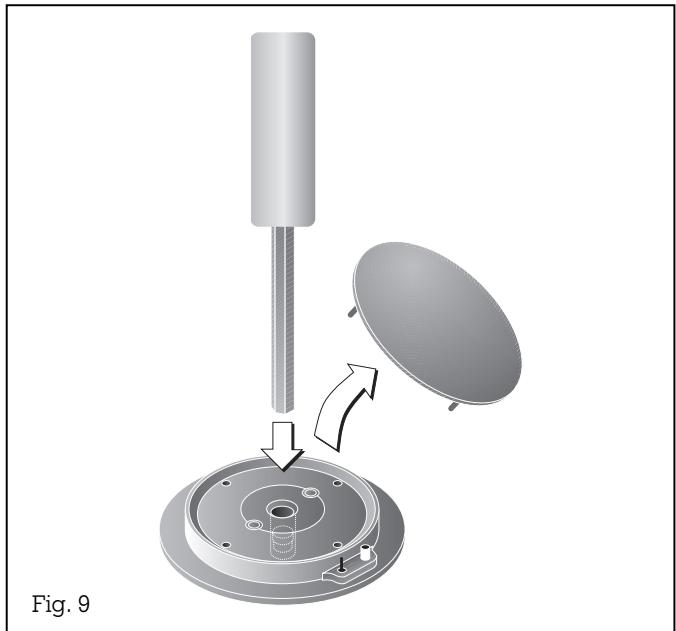
Fig. 9
See table on Pages 10 - 11 for details of nozzle settings.
Replacing the main nozzle 2 Proceed as follows:
- The main nozzle 2 is visible after detaching the burner cover (see Fig. 9). It is unscrewed with a special screw key.
- Unscrew the nozzle and insert the new nozzle as specified in the main nozzle table. The nozzle must be screwed in fully and firmly (torque 1.5 Nm) (metallic seal).
- Please do not forget to stick the new adhesive label included with the nozzle set over the old adhesive label on the gas connection, thus documenting the changeover to a different gas type.
Checking functions
The flames are adjusted correctly if no yellow tips are visible and if they do not go out when switching over swiftly from the high to the low setting.
Adjusting the primary air
The primary air setting for different gases is only defined by the diverse nozzle shapes and therefore does not require adjustment.
7.4 Installing the appliance
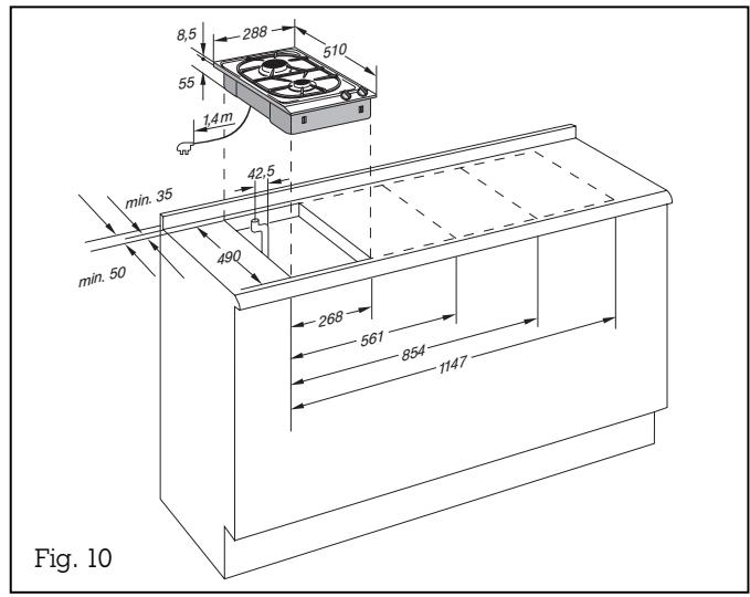
- Produce the recess for one or several Vario appliance(s) in your worktop. Proceed as indicated on the installation sketch and the dimension table. The dimension table contains details of the space requirement for the trim between the appliances.
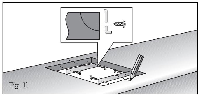
Important: the angle between the cut surface and the worktop must amount to 90^ (Fig. 10).
- Mark the centre of the recess exactly.
Secure the securing rails on the front and rear edges of the recess. Make sure that the lugs of the securing rails lie on the worktop and that the centre marking of the securing rails is precisely flush with the centre marking on the worktop (Fig. 11).
Secure the cover on the appliance before installation. See assembly instructions VD 201-010.
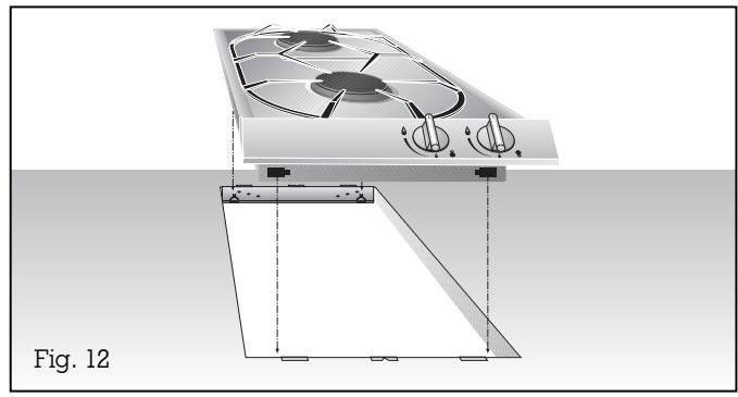
- Lower the appliance into the worktop. Make sure that the engaging lugs on the appliance lie exactly on the clamping springs. Press the appliance firmly into the worktop. The engaging lugs on the appliance "snap" into the clamping springs (Fig. 12).
Note: When installing the appliance in granite or marble worktops, have the holes produced by a specialist or stick on the securing rails with a temperature-resistant 2-component adhesive (metal on stone).
Note:
Several appliances can also be installed in individual recesses, as long as a minimum clearance of 40mm is kept to between the appliances.