MIG350 / MIG500 - Welding machine JASIC - Free user manual and instructions
Find the device manual for free MIG350 / MIG500 JASIC in PDF.
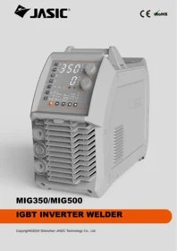


| Product type | Professional MIG/MAG welding machine |
| Brand | JASIC |
| Model | evo20 mig350 n2se2 / mig500 n2sf2 |
| Category | Arc welding machine |
| Technology | High frequency IGBT inverter |
| Welding processes | MIG/MAG, MMA (coated electrode), Lift-TIG |
| Maximum output current | 350 A for MIG350, 500 A for MIG500 |
| Power supply | Three-phase 380 V ± 15%, 50/60 Hz |
| No-load voltage | Approximately 60-70 V |
| Duty cycle | 60% at maximum current (forced cooling) |
| Wire diameter | 0.8 / 1.0 / 1.2 mm (steel, stainless steel, flux-cored) |
| Wire feed speed | Continuously adjustable (approximately 1.5 - 20 m/min) |
| Control panel | Digital with JOB synergic presets |
| JOB function | Parameter memory for steel, stainless steel, flux-cored |
| Cooling | Thermostatically controlled fan |
| Thermal protection | Automatic shutdown in case of overheating with alarm |
| Repairability | Electronic boards and spare parts available from the manufacturer |
| Maintenance | Regular cleaning of ventilation slots and checking connections |
| Safety standards | Compliant with EN60974-1 standard |
| Dimensions (L × W × H) | Approximately 600 × 300 × 550 mm (depending on model) |
| Weight | Approximately 35 kg (MIG350) / 55 kg (MIG500) |
| Included accessories | MIG torch, ground clamp, power cable, documentation |
Frequently Asked Questions - MIG350 / MIG500 JASIC
User questions about MIG350 / MIG500 JASIC
0 question about this device. Answer the ones you know or ask your own.
Ask a new question about this device
Download the instructions for your Welding machine in PDF format for free! Find your manual MIG350 / MIG500 - JASIC and take your electronic device back in hand. On this page are published all the documents necessary for the use of your device. MIG350 / MIG500 by JASIC.
USER MANUAL MIG350 / MIG500 JASIC

MIG350/MIG500
IGBT INVERTER WELDER
Congratulations on choosing JASIC equipment! This operating manual contains important information on the use and maintenance of this product, as well as safe handling of the product. Please refer to technical parameters of the equipment in Technical Parameter in this manual, and read the manual carefully before using the equipment for the first time. For your own safety and that of your working environment, please pay particular attention to the safety instructions in the manual and operate the equipment according to the instructions. For more information on JASIC products, please contact JASIC Technology, consult an authorized JASIC dealer or visit JASIC website at www.jasictech.com.
Disclaimer
Shenzhen JASIC Technology Co., Ltd. solemnly promises that this product is manufactured according to relevant domestic and international standards, and that this product conforms to EN60974-1 International Safety Standard. The relevant design scheme and manufacturing technology adopted in this product are protected by patents.
- While every effort has been made to ensure that the information contained in this manual is accurate and complete, no liability will be accepted for any errors or omissions due to the operation not according to this manual.
- JASIC reserves the right to change the manual at any time without prior notice.
- Though contents in this manual have been carefully checked, there might be inaccuracies. Please contact us in case of inaccuracy.
- Do not copy, record, reproduce or transmit the contents of this manual without prior permission from JASIC.
Manufacturer: Shenzhen JASIC Technology Co. Ltd Registered Trademark: JASIC
Registered Address: No.3 Qinglan 1st Road, Pingshan District, Shenzhen, Guangdong, China Postcode: 518118
Tel: +86 (0755) 8670 6250
Website:www.jasictech.com
Fax: +86 (0755) 27364108
E-mail: sales@jasictech.com
Table of Contents
- Safety precautions....7
1.1. General safety....7
1.2.Precautions 9
-
Description of symbols ...... 10
-
Product overview 12
-
Technical Parameters ...... 14
-
Installation 16
5.1. External interface description.... 17
5.2. Power supply installation 18
-
Control panel 25
-
Welding function operation....36
7.2. MMA operation 46
7.3. Lift-TIG operation....48
7.3.5. Turn off the power supply after welding (Same as 7.1.7)....49
7.5. Function and use of wireless or remote controller 50
7.6. Software upgrading function operation....50
-
Maintenance and care....52
-
Troubleshooting....53
9.1. Troubleshooting of common problems 53
9.2 Fault alarms and solutions....57
9.3. Common problems in MIG mode....59
- Packaging, Transportation, Storage, and Waste Disposal 60
10.1. Transportation requirements....60
10.2. Storage conditions....60
10.3. Waste disposal 60
- After-sales service 61
11.1. Warranty card....61
11.2. Repair 61
Appendixes 62
Appendix 1: Wiring diagram of the machine....62
Machine wiring diagram 1--MIG350 62
Machine wiring diagram 2--MIG500 63
Appendix 2: Common spare parts list....64
Common spare parts list 1--MIG350 64
Spare parts list--MIG350 65
Common spare parts list 2--MIG500 66
Spare parts list--MIG500 67
Appendix 3: Package and spare parts....68
For your safety, please read this manual carefully before installing and operating this JASIC equipment.
Pay extra attention to all content marked with " !".
All operations must be carried out by professional, suitably qualified persons!
1. Safety precautions
1.1. General safety

Warning! During welding, arc and cutting smoke may cause harm to you and
others. Therefore, you shall take protective measures during welding. For details, refer to the safety protection guidelines for operators that meet the manufacturer's accident prevention requirements.
 | Only qualified personnel should operate this machine! ·Always use the appropriate personal protective equipment. ·The operator must be a special equipment operator with a valid Metal Welding (Gas Cutting) Operation certificate! ·Do not carry out any maintenance with the power on the machine |
 | Electric shock—May cause serious injury or even death! ·Install grounding devices according to application standards. ·Do not touch any live parts with your exposed skin, wet gloves, or wet clothes. ·Make sure that you are insulated from the ground and the workpiece. ·Make sure that the workstation is safe. |
 | Fumes and gases—May be hazardous to your health. ·Locate the equipment in a well-ventilated position and keep your head out of the fume. Do not breathe the fume. ·When welding, use ventilation or extraction devices to maintain a well-ventilated working environment. |
 | Arc rays—May injure the eyes and burn the skin. ·Use a suitable welding mask and wear protective clothing to protect your eyes and body. ·Protect bystanders from hazards with suitable masks or shading curtains. |
  | Improper use and operation may lead to fire or explosion ·Welding sparks may cause a fire. Please confirm that there are no flammable materials near the welding station and pay attention to safety and fire prevention. ·The fire extinguishing devices shall be set up nearby and the trained personnel proficient in using them shall be available. ·Do not weld any closed containers. ·It is prohibited to use the machine for pipeline thawing.Hot workpieces may cause serious burns·Do not touch hot workpieces with bare hands.·There should be a cooling time when using the welding torch continuously. |
 | Noise——Excessive noise may be harmful to hearing·Protect your ears with ear shields or other hearing protectors.·Remind nearby personnel that noise may be potentially hazardous to hearing. |
 | Magnetic field affects cardiac pacemaker·Before consulting a doctor, pacemaker users should stay away from the welding site. |
 | Moving parts may cause personal injury·Keep away from moving parts such as fans.·Various protective devices such as doors, panels, covers, and baffles, etc. should be tightly closed and put in place. |
 | Fault--When encountering difficulties, seek help from professionals.·For difficulties during installation and operation, please follow the relevant content of this manual for troubleshooting.·If you still cannot fully understand the content contained in this manual after reading, or cannot solve the problem as per the instructions in this manual, immediately contact your supplier or the service center of JASIC to seek professional assistance. |
1.2.Precautions

Warning! If the equipment tips over or falls, it may be damaged, or personal injury may result. Therefore, refer to the handling and placement methods indicated on the outer package and use a trolley or similar handling equipment with a sufficient load-carrying capacity to handle the equipment.

Warning! The handle or strap on the welder is only suitable for carrying the welder by hand. When lifting the welder using a crane or other machines, put the welder in a container with a sufficient load-carrying capacity and then lift the welder together with the container.

Warning! The welder has over-voltage, over-current, and over-heating protection circuits. Thus, the welder will stop working when the mains voltage, output current, or internal temperature exceeds the set value. However, if the cutter is still in use in a conditions exceeding the set value (such as over-voltage), the welder may be damaged.
1) When the operator's movement is limited by the surroundings (for example, the operator can only bend his knees, barefoot, or lie down during operation), the operator shall practice proper insulation and avoid
direct contact with conductive parts on the equipment.
2) Do not use the welder in closed containers in narrow spaces where conductive components cannot be removed.
3) Do not use the welder in humid environments where the operator is prone to the risk of electric shock.
4) Do not weld in sunlight or rain, and no water or rainwater shall seep into the welder.
5) Do not perform gas shielded welding in an environment with strong air flow.
6) Avoid using the welder in dusty area or environment with corrosive chemical gas.
7) The ambient temperature should be between -10°C to 40°C during operation and between -25°C to 50°C during storage.
8) The welding should be performed in a relatively dry environment with a humidity of no more than 90%.
9) The inclination of the welder should not exceed 10° .
10) Ensure that the input power voltage does not exceed ± 15% of the machine's rating voltage.
11) Be cautious that the welder may fall from a high place during welding.
2. Description of symbols

Warning! Read the explanation

High-voltage warning

WEEE tag

Current unit "A"
m/min
Wire feed speed (m/min)

Base metal thickness (unit: mm)

Time unit (unit: seconds)

Voltage (unit: V)

MIG "Inductance"/MMA "arc force current"

MIG burnback time (unit: ms)
JOB
Channel indicator (10 groups for each welding mode)

MIG welding parameters

MIG crater welding parameters

Overheat protection indication

"Fault" indication

VRD function indication

MMA mode

MIG mode

TIG mode

Welding mode selection
Steel Ar80% CO220%
Gas mixture containing 80% argon and 20% CO2 for carbon steel welding
Al Ar100%
100% argon for aluminum welding
Steel Ar93% CO25% O22%
Gas mixture containing 93% argon, 5% CO 2 , and 2% oxygen for carbon steel welding
CrNi Ar98% CO22%
Gas mixture containing 98% argon and 2% CO 2 for stainless steel welding
Steel FluxCored Ar80% CO220%
Gas mixture containing 80% argon and 20% CO 2 for flux-cored carbon steel welding
Steel FCW-SS
Carbon steel self-shielded flux cored arc welding


Welding type selection: base metal and gas selection function for welding
φ 0.8
φ 1.0
φ 1.2
φ 1.6
Wire diameter

MIG two-step mode

MIG four-step mode

MIG repeat mode
● ● ●
MIG spot welding mode

Remote control function

MIG synergic function

Saving function

Call function

Wire check function

Gas check
3. Product overview

MIG350/500 series
This series of welders is a digital multi-function GMAW inverter welder with excellent performance and advanced technology, which has three welding modes, such as DC MIG, DC MMA, and Lift-TIG. It can be widely used for welding various metal materials, such as carbon steel, low-alloy steel, aluminum-magnesium alloy, and stainless steel. In the DC MIG mode, parameters such as welding voltage, welding current, wire feed speed, and sheet thickness can be preset. A built-in "Synergic" expert parameter database is provided for welding wires of different materials and diameters. The operator needs to set welding current, wire feed speed, or sheet thickness only after choosing the welding wire type, shielding gas, and welding wire diameter via the panel. The welder can match the appropriate welding voltage automatically to achieve an excellent welding effect. Both the MMA and lift-TIG modes also make the welder applicable in more application scenarios. The unique electrical structure and zoned diverted air passage design inside the machine increases heat dissipation efficiency and balances the temperature rise of power devices, thus improving the duty cycle of the machine. Due to the unique sealed air passage, the machine can effectively prevent dust drawn in by the fan from damaging power devices and control circuits, thus greatly improving the reliability of the machine.
The main functions are as follows:
◆ There are three arc welding modes, including MIG, MMA, and lift-TIG.
◆ In the MIG mode, welding voltage, welding current, wire feed speed, sheet thickness, and welding inductance can be preset.
◆ Gas and wire check function
◆ "Synergic" function: It is necessary to choose welding wire type, shielding gas, and wire diameter. It's only required to set welding current, wire feed speed, or sheet thickness. The
welder will match the welding voltage automatically.
◆ Multiple MIG torch options include: ordinary standard torch, digital standard torch, push-pull torch, and spool torch.
◆ In the MMA mode, the welding current, arc force current, and hot start current can be preset.
◆ The VRD function reduces the no-load voltage outputted by the welder to below the safe voltage level that can be withstood by the human body: making it safer and more stable in the use of electricity.
◆ Anti-stick function: Prevents excessive output current from burning the electrode and base material when welding sticks to the electrode.
◆ On-demand fan control: This function can save electricity, prolong the lifespan of the fan, and reduce accumulation of dust inside the machine.
◆ Automatic parameter saving function: After shutdown, the data will not be lost. When the welder is restarted, it is retain the parameters set before shutdown.
◆ Parameter factory reset function.
◆ Standby function: In the MIG or lift-TIG mode, the welder may enter the standby state if it is not used for a long time.
◆ Remote control function: The welder can be equipped with functions such as wireless handheld remote control, wireless foot pedal remote control, wired foot petal remote control, wireless helmet remote control, and mobile phone APP.
- Technical Parameters
| Descriptions | Unit | MIG350/MIG500 Parameters | |
| Product model | / | MIG350 | MIG500 |
| Input power supply voltage | VAC | 3~AC400V±15% 50/60Hz | 3~AC400V±15% 50/60Hz |
| Rated input current (AC400V) | A | 25@MIG18.9@TIG25@MMA | 44.1@MIG32.3@TIG41.1@MMA |
| Rated input power (AC400V) | kVA | 17.3@MIG13.08@TIG17.3@MMA | 30.52@MIG22.35@TIG28.44@MMA |
| Output voltage adjustment range (MIG) | V | 10~40 | 10~48 |
| Wire feeding speed range (MIG) | m/min | 2~24 | 2~24 |
| Output current range (MIG) | A | 30~350 | 30~500 |
| Output current adjustment range (TIG) | A | 20~350 | 20~500 |
| Output current range (MMA) | A | 20~350 | 20~500 |
| Arc force current range | A | 0~200, defaulted to 0 | 0~200, defaulted to 0 |
| Hot start current range | A | 0~200, defaulted to 100 | 0~200, defaulted to 100 |
| No-load voltage | V | 75 | 82 |
| VRD voltage | V | 13 | 13 |
| Rated output | A·V | 350A/31.5V@MIG350A/34V@MMA350A/24V@TIG | 500A/39V@MIG500A/40V@MMA500A/30V@TIG |
| Efficiency (%) | / | 91.03@MIG88.19@TIG 90.78@MMA | 90.9@MIG89.8@TIG 91.3@MMA |
| Duty cycle (%) | / | 50 | 40 |
| Power factor | / | 0.92@MIG | 0.94@MIG |
| 0.91@TIG0.92@MMA | 0.93@TIG0.94@MMA | ||
| Insulation class | / | H | H |
| Enclosure class | / | IP23S | IP23S |
| DimensionsL*W*H | mm | 660*280*570 | 660*280*570 |
| Net weight | Kg | 27.2 | 30 |
| Gross weight | Kg | 30.5 | 33.2 |
| Power consumption in idle state | W | <50 | <50 |
| Static and external characteristics | / | CC/CV | CC/CV |
| Pollution level | / | Level 3 | Level 3 |
5. Installation

Warning! All connections shall be made with the power supply turned off.
Warning! Electric shock may cause death; after power failure, there is still a high voltage on the equipment, do not touch the live parts on the equipment. Warning! Incorrect voltage may damage the equipment.
Warning! This product meets the requirements of Class A equipment in EMC requirements and is not to be connected to a residential low-voltage power supply grid.

Wiring diagram of three-phase distribution box
- Power switch of distribution box
- Use a fuse with a rated current of not less than 60 A.
- The power cable of the MIG500 welder should be 4 × 4 mm2 or above.
The MIG350 welder should use a power cable of 4 × 2.5 mm2 or above. - Yellow/green grounding wire (It is grounded instead of being connected to the neutral wire!).
Please connect the power cable by the method shown in the figure or other correct ways.

Warning: Do not operate with electricity!
- The wiring of the machine can only be carried out by professional electricians.
- Do not connect two welders to the same switch box.
- If the casing is grounded, wire 4 does not need to be grounded.
5.1. External interface description
MIG350 and MIG500 series

(Front panel view)
(Rear

panel view)
| S/N | Material name | S/N | Material name |
| a | Rotary switch | g | Power supply interface of water cooler |
| b | Input power cable | h | Output positive quick-connection socket (rear) |
| c | Heater socket (optional) | i | Output positive quick-connection socket (front) |
| d | Type-C interface (for software upgrading or charging) | j | Control cable interface of wire feeder (front) |
| e | Group control interface (optional) | k | Output positive quick-connection socket |
| f | Control cable interface of wire feeder (rear) | l | Wireless Bluetooth transceiver module |
5.2. Power supply installation

Warning! The electrical connection of the machine must be completed by electricians with qualification certificates.
Warning! All connections shall be made with the power supply turned off. Warning! Incorrect voltage may damage the equipment.
1) Ensure the input voltage value is within the specified input voltage range.
2) Ensure that the power switch of the welder is turned off.
3) Connect the input power cable to the input terminal or plug the power cable into the corresponding socket (if any) and ensure good contact.
4) Ensure the power supply is properly grounded. (As shown in the diagram, the European plug has a grounding terminal, so no additional grounding is required.)

Note! When extending the input power cable is required, use a cable with a larger cross-sectional area to reduce voltage drop. The recommended cable cross-section is 4X2.5 mm2 for the MIG350 welder and 4X4 mm2 or larger for the MIG500 welder.
5.3. MIG welding torch and earth cable connection
Pay attention to the polarity of wiring before performing MIG welding. Generally, there are two connection methods for DC welder: DCEN and DCEP.
DCEP: The welding torch is connected to the positive polarity, and the workpiece to the negative polarity;
DCEN: The electrode holder is connected to the negative polarity, and the workpiece is connected to the positive polarity;
When this series of welders works in the MIG mode, DCEN is generally used for other MIG types except for carbon steel flux-cored self-shielded welding, which uses DCEP.
5.3.1 DCEP

(Split connection)

(Combined connection)
1) Ensure that the power switch of the welder is turned off.
2) Insert the welding torch plug into the central socket interface at the lower part of the front panel of the wire feeder and tighten it firmly in a clockwise direction.
3) Insert the cable plug with an earth clamp into the negative output socket at the lower part of the front panel of the welder and tighten it firmly in a clockwise direction.
4) Insert the welding cable plug with an earth clamp into the positive output socket at the lower part of the front panel of the welder and tighten it firmly in a clockwise direction.
Connect one end of the cable to the quick-connection socket on the rear panel of the wire feeder and then lock it firmly with a nut.
5) Connect one end of the gas hose to the gas inlet nozzle on the rear panel of the wire feeder, and connect the other end to the output interface of the shielding gas regulator; secure both connections firmly with clamps.
5.3.2 DCEP

1) Ensure that the power switch of the welder is turned off.
2) Insert the welding torch plug into the central socket interface at the lower part of the front panel of the wire feeder and tighten it firmly in a clockwise direction.
3) Insert the cable plug with an earth clamp into the positive output socket at the lower part of the front or rear panel of the welder and tighten it firmly in a clockwise direction.
4) Insert the welding cable plug with an earth clamp into the negative output socket at the lower part of the front panel of the welder and tighten it firmly in a clockwise direction.
Connect one end of the cable to the quick-connection socket on the rear panel of the wire feeder and then lock it firmly with a nut.
5) Connect one end of the gas hose to the gas inlet nozzle on the rear panel of the wire feeder, and connect the other end to the output interface of the shielding gas regulator; secure both connections firmly with clamps.
Note! During carbon steel flux-cored self-shielded welding, a special knurled wire feed roller should be used. Additionally, DCEN should be used. During aluminum-magnesium alloy welding, a special wire feed roller with a U-shaped groove, a contact tip for Aluminum wire, and a wire liner with a diameter of 2.0 should be used for aluminum welding. Additionally, "DCEP" should be used.
5.4.MMA electrode holder and earth cable connection

Pay attention to the polarity of wiring before performing MMA welding. Generally, there are two connection methods of DC welder: DCEN and DCEP.
DCEP: The electrode holder is connected to the positive polarity, and the workpiece to the negative polarity;
DCEN: The electrode holder is connected to the negative polarity, and the workpiece to the positive polarity;
The operator can also choose DCEN based on the base metal and electrode. Generally speaking, DCEP is recommended for basic electrodes (i.e., electrode connected to the positive polarity), while no special provisions are made for acid electrodes.
1) Ensure that the power switch of the welder is turned off.
2) Insert the cable plug with an electrode holder into the corresponding socket on the front panel of the welder and tighten it firmly in a clockwise direction.
3) Insert the cable plug with an earth clamp into the corresponding socket on the front panel of the welder and tighten it firmly in a clockwise direction.
Note! If the workpiece is far away from the welder, and the secondary cables (electrode holder cable and earth cable) used are long, the recommended cross-sectional area of the cables used should be appropriately larger to reduce the cable voltage drop.
5.5. TIG welding torch and earth cable connection

(Lift-TIG connection diagram: DCEN)
1) Ensure that the power switch of the welder is turned off.
2) Insert the welding torch plug into the negative output socket at the lower part of the front panel of the welder and tighten it firmly in a clockwise direction.
3) Insert the cable plug with an earth clamp into the positive output socket at the lower part of the front panel of the welder and tighten it firmly in a clockwise direction.
Note! The positive and negative polarities should not be reversed as this will prevent normal welding operation.
4) Connect one end of the gas hose to the output interface of the shielding gas regulator and secure it firmly with a clamp.
Note! If the workpiece is far away from the welder, and the secondary cables (electrode holder cable and earth cable) used are long, the recommended cross-sectional area of the cables used should be appropriately larger to reduce the cable voltage drop.
5.6. Installation of wireless Bluetooth transceiver module

1) Remove the left cover of the machine by unscrewing the screws.
2) Insert Bluetooth module, a shown in the figure above, into the Bluetooth module hole of the front panel of the welder.
3) Insert the connecting cable of the Bluetooth module into the 7P terminal block CN19 on the control panel PK-530, as shown in the figure to the upper right.
5.7. APP transceiver module installation (optional)

1) Remove the left and right covers of the machine by unscrewing their respective screws.
2) Insert APP module b on the left side of the machine shown in the figure above into the APP fixing bracket of the front panel and secure it firmly.
3) Insert the connecting cable of the APP module to the 6P terminal block CN12 of control panel PK-530, as shown in the figure to the upper right.
Note! Please check with the seller whether the hardware and software versions of the machine support the APP module function before purchase.
5.8. Type-C module installation


1) Remove the left cover of the machine by unscrewing the screws.
2) Insert module c on the left side of the machine shown in the figure above into the Type-C module slot on the rear panel.
3) Insert the connecting cable of the Type-C module to 5P terminal block CN26 of control panel PK-530, as shown in the figure to the upper right
6. Control panel
6.1. Overview


(MIG350 operation panel)
a.Parameter display a
b.Parameter display b
c.Welding mode selection
d.Selection of welding wire and shielding gas
e.Operation mode selection
f.Wire diameter selection
g.Remote control function selection
h.MIG synergic function
selection
i.Channel saving function
j.Channel call function
k.Switchover among main welding section/crater
welding section parameters
I.Wire check
m.Gas check
n.Protection/alarm indicator
o.VRD function indicator
p.Parameter switch and adjustment knob A
q.Parameter switch and
adjustment knob B
a. Parameter display a

"Parameter display a" is used to display current parameter, wire feed speed, sheet thickness, time parameters, and error code.
1) Before the welding, the current parameter setting is displayed. If no operation is performed for a long time, it jumps to display the default parameter automatically.
2) During welding, the actual output current value is displayed.
3) When the welding is finished, it displays the actual current value saved before the welding ends.
4) When the machine enters the engineer mode menu or its factory settings are reset, the countdown is displayed.
5) During the barcode query, the machine's barcode is displayed.
6) When the product is not working correctly, an error code is displayed.
7) When the synergic function is enabled in MIG mode, the synergic ammeter set by the setting parameter number "F12" in the engineer menu (for details, see section 6.4) displays default parameter settings in the default display option, including current, wire feed speed, and sheet thickness. When the synergic function is disabled in MIG mode, it displays the wire feed speed setting.
8) In the MMA or lift-TIG mode, the current parameter settings are displayed by default.
b. Parameter display b

"Parameter display b" is used to display voltage parameter, inductance or arc force current, burnback time, and saving channel parameter.
1) Before the welding, the current parameter setting is displayed. If no operation is performed for a long time, it jumps to display the default parameter automatically.
2) During welding, the actual output voltage value is displayed.
3) When the welding is finished, it displays the actual current value saved before the welding ends.
4) In the MIG mode, it displays the voltage setting by default. In the MMA mode, it displays the VRD voltage by default when the VRD is switched on, and the no-load voltage when the VRD is switched off. In the lift-TIG mode, it displays the VRD voltage by default.
C. Welding mode selection

Before welding, press the welding mode selection key 🧑 to switch among the MIG, MMA, and lift-TIG modes. The user can choose the desired welding mode as required.
1). The indicator is on, indicating that the machine is operating in MIG/MAG mode;
2) The indicator is on, indicating that the machine is operating in MMA mode.
3) The indicator is on, indicating that the machine is operating in Lift-TIG mode;
Note! When the welder is in the welding state or the torch trigger is pressed, the welding mode selection function is disabled.
d. Selection of MIG welding wire and shielding gas
Steel
Ar80% CO 2 20%
CrNi
Ar98% CO 2 2%
Al Ar100%
Steel FluxCored
Ar80% CO 2 20%
Steel
Ar93% CO 2 5% O 2 2%
Steel FCW-SS


to switch the welding
1) In the MIG mode, press the welding type selection key ☐ ☐ to switch the welding wire type and shielding gas.
2) The corresponding welding type indicator comes on, indicating that the current welding wire type and shielding gas have been selected.
e. Wire diameter selection
φ 0.8
φ 1.0
φ 1.2

1) In the MIG mode, press the corresponding function switchover key to select the selectable welding wire diameter for the corresponding welding type.
2) The corresponding welding wire diameter indicator lights up, indicating that the welding wire diameter has been selected.
f. Operation mode selection
↓↑
↑↑
()
...

1) In the MIG mode, press the corresponding function switch key ⬇ to select the 2T, 4T, repeat, or spot welding mode.
2) The indicator is on, indicating that it is operating in 2T operation mode;
3) The indicator is on, indicating that it is operating in 4T operation mode;
4) The indicator is on, indicating that it is operating in repeat mode;
5) The indicator is on, indicating that it is operating in spot welding mode;
g. Remote control function selection


Wired remote control
1) Enter the engineer mode menu (for details, see section 6.4) to set the parameter designated with serial number "F09" to "1". Then, save the setting and exit the engineer mode.
2) Before welding, press the remote control function key to turn on or turn off the remote control function; 3) If the indicator is on, it indicates that the remote control function is enabled. If the indicator is not on, it indicates that the remote control function is disabled. Wireless remote control
1) Set the remote control mode to wireless remote control mode
Enter the engineer mode menu (for details, see section 6.4) to set the parameter designated with serial number "F09" to "0". Then, save the setting and exit the engineer mode.
2) Wireless pairing
Before welding, press and hold the panel remote control function key 📂 and the pairing key 📃 of the wireless remote controller simultaneously for 2 seconds to pair the
wireless remote controller. During pairing, the blue wireless receiver module indicator flashes; after successful pairing, the remote control mode indicator will light up. At the same time, the blue indicator 🏠 on the wireless receiver module will remain lit, and the welder display window will display "OK".
After the pairing is successful, it is possible to adjust the parameters via the wireless remote controller.
3) Wireless connection off
After successfully connecting the remote controller, press and hold the remote control
function of the panel ☐ or the pairing key on the wireless remote controller for 📄2
seconds to disconnect the remote controller. After disconnection, the welder display window displays "FAL" symbol. In the meantime, the wireless transceiver module indicator

remains green.
Note: For different remote controller types, the pairing key symbol may vary. Therefore, the actual symbol should take precedence. For the specific operation
method, refer to the remote controller instructions.
h. MIG synergic switch selection
SYN
1) In the MIG mode, press the one-in-all switch key SYN to enable or disable the one-in-all function;
2) If the indicator comes on, it indicates that the one-in all function is enabled. If the indicator comes off, it indicates that the synergic function is disabled.
3) In the synergic mode, the welder automatically matches the welding parameters based on the set current parameter, wire feed speed, sheet thickness, welding type, and welding wire diameter.
i. Saving function
B
1) In any "Welding mode", gently press the "Saving key" to enter the "Saving mode". In this case, the "Saving indicator" and the "JOB indicator" come on, and the corresponding digital display of the "JOB indicator" shows the current "JOB number". The parameter group numbers are represented by "n01", "n02", "n03"......"n10". Each "Welding mode" has ten JOB numbers (parameter group channels);
2) The corresponding encoder of the "JOB indicator" can be rotated to switch the "JOB number". Pressing the key on the encoder will display other parameters on the corresponding digital tube of the "JOB indicator";
3) After the "JOB number" is selected, gently press the "Saving key" to save parameters, and exit the "Saving mode"; in this case, the "Saving indicator" and "JOB indicator" will turn off, and the corresponding digital tube of the "JOB indicator" will display the first parameter.
j. Call function

1) Gently press the "Call key" to enter the "Call mode". In this case, both the "Call indicator" and the "JOB indicator" will light up, and the digital tube of the "JOB indicator" will display the "JOB number";
2) The corresponding encoder of the "JOB indicator" can be rotated to switch the "JOB number". Pressing the key on the encoder will display other parameters on the corresponding digital tube of the "JOB indicator". The digital tube can display the parameter corresponding to the "JOB number" by switching the "JOB number", but the parameters cannot be adjusted;
3) After the "JOB number" is selected, gently press "Call key" to call parameters, and exit the "Call mode"; in this case, the "Call indicator" and "JOB indicator" will turn off, and the corresponding digital tube of the "JOB indicator" will display the first parameter. At this moment, the parameter can be adjusted normally.
k. Switchover among main welding section/crater welding section parameters


1) Gently press the key to switch between the main welding section and the crater welding section. The main welding section is selected by default.
2) Key response condition: The key responds in MIG "4-step" and "Repeat" modes.
3) When switching to the crater welding section occurs, the welding parameters for the crater welding section can be adjusted.
I. Wire check function switch

1) In the MIG mode, press the wire check function key to start the wire check function, and release the key to disable the function.
2) If the corresponding indicator is on, it indicates that the wire check function has started feeding wire.
m. Gas check function switch

1) In the MIG mode, press the gas check function key to enable or disable the gas check function.
2) When the indicator comes on 1, it indicates that the gas check function is enabled and
the gas valve is open. When the indicator comes off, it indicates that the gas check function is disabled, and the gas valve is closed.
Note that the gas check function will automatically stop in 20 seconds to avoid wasting gas.
n. Protection/alarm indicator

If the overheat indicator lights up, it indicates that the welder has entered overheat protection mode and has stopped output.
In this case, do not shut down the welder but wait for a while after stopping the welding. After the over-heat indicator comes off, the welding can resume.

If the alarm indicator comes on, it indicates that the welder has entered abnormality protection mode and has stopped output.
In this case, restart the welder. If the alarm is still present, please contact the manufacturer's after-sales service.
o. VRD function indicator
1) When the VRD function remains disabled during welding, the VRD indicator is not lit.
2) When no welding is performed and the VRD function is enabled, the VRD indicator is

, indicating that the VRD function remains normal.
3) When the VRD function is enabled and no welding is performed, the VRD indicator is red

, indicating that the VRD function is abnormal.
4) When the VRD function is enabled during welding, the VRD indicator is not lit.
Note: The VRD switch is located at "SW1-1" on the main control board (PK-530) in the
machine. "ON"
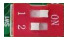
indicates that the VRD function is enabled, and "OFF"

indicates that the VRD function is disabled.
p. Parameter adjustment knob A
A m/min 1/4 S

1) In the MIG mode, when the "Synergic" function is enabled, set the wire feed speed; press the knob to change and display parameters such as current, wire feed speed, sheet thickness, and spot welding time, and set them.
2) In the MMA or lift-TIG mode, it is possible to set the current parameter.
3) Rotate the adjustment knob to adjust the parameters.
4) Rotate the knob clockwise to increase the parameter value, and counterclockwise to decrease it.
5) When the adjustment knob is rotated, the adjusted parameter is displayed in the parameter display area.
q. Parameter adjustment knob B
V □ JOB

1) In the MIG mode, press the knob to change and display parameters such as voltage, burnback time, and saving channel, then set them.
2) In the MIG mode, press the knob to set the arc force current.
3) Rotate the adjustment knob to adjust the parameters.
4) Rotate the knob clockwise to increase the parameter value, and counterclockwise to decrease the parameter value;
5) When the adjustment knob is rotated, the adjusted parameter is displayed in the parameter display area.
6.2. Barcode display
1) When no welding is performed, press and hold the "Welding mode selection" key

and "Parameter adjustment knob A" for 3 seconds to display the machine's barcode in the display window.
2) Press any key or wait for 20 seconds to exit the machine's barcode display.
3) The barcode is displayed in nine data groups next to "Parameter display a" in the display window, which include "1.XY", "2.XY"....."9.XY", where X and Y are digits ranging from 0 to 9. The barcode can be interpreted by referring to the following table:
| Displayed data | Data meaning |
| 1.XY | X and Y indicate the first and second numbers or letters of the barcode, respectively. |
| 2.XY | XY indicates the third number/letter of the barcode, which ranges from 11 to 45. The corresponding barcode characters are D~Z, representing years. |
| 3.XY | XY indicates the forth number or letter of the barcode, which ranges from 01 to 12. The corresponding barcode characters are 0~Z, representing months. |
| 4.XY | XY indicates the fifth number or letter of the barcode, which ranges from 01 to 31. The corresponding barcode character is 0~V, representing dates. |
| 5.XY | X and Y indicate the sixth and seventh numbers or letters of the barcode, respectively. |
| 6.XY | X and Y indicate the eighth and ninth numbers or letters of the barcode, respectively. |
| 7.XY | X and Y indicate the tenth and eleventh numbers or letters of the barcode, respectively. |
| 8.XY | X and Y indicate the twentieth and twenty-first numbers or letters of the barcode, respectively. |
| 9.XY | X and Y indicate the twenty-second and twenty-third numbers or letters of the barcode, respectively. |
The numbers from the twelfth digit to nineteenth digit of the barcode are an internal number fixed by the company, which is displayed in the display window.
The machine's barcode can be obtained by reading and arranging the nine data groups, as well as skipping the numbers from the twelfth digit to the nineteenth digit of the barcode.
6.3. Resetting to the factory setting
1) When no welding is performed, press and hold the "Welding mode selection" key for 5 seconds to restore factory settings.
2) With the key pressed and held for 5 seconds, the display window counts down from 3. After the countdown ends, the cutter is reset to the factory setting. If you release the button midway to exit the countdown, the welder cannot be reset to factory settings.
- The factory settings are as follows:
| Option | Description | Reset parameter valuesMIG350 series | Reset parameter valuesMIG500 series | Remarks |
| MIG parameters | Burnback time | 200 ms | 200 ms | |
| Burnback voltage | 13 V | 13 V | ||
| Induction | 0 | 0 | ||
| Pre-flow time | 0.1S | 0.1S | ||
| Post-flow time | 0.5S | 0.5S | ||
| Welding voltage | 19.0 V | 19.0 V | ||
| Welding speed | 5 m/min | 5 m/min | ||
| Crater welding voltage | 19.0 V | 19.0 V | ||
| Crater wire feed speed | 5 m/min | 5 m/min | ||
| MMA parameters | Arc force current | 40A | 40A | |
| Hot start current | 100A | 100A | ||
| Welding current | 130A | 130A | ||
| Lift-TIG parameters | Welding current | 100A | 100A |
6.4. Engineer mode menu function
This series of welders has an engineer mode menu function, allowing users to set and change default back-end parameters and functions as follows:
1) With the welder started, press and hold "Parameter adjustment knob A" for 5 seconds.
2) Press the "Current parameter adjustment knob" for 2 seconds to start the 3-second countdown. After the countdown ends, the parameter serial number, e.g. "F01", is displayed next to "Parameter display a" in the display window. Display the set value corresponding to the current parameter serial number next to the "Parameter display b".
3) Rotate the "Parameter adjustment knob A" to select the parameter serial number or function that needs to be set in the back-end.
4) Rotate the "Parameter adjustment knob B" to change the set value corresponding to the displayed parameter serial number.
5) Press the "Parameter adjustment knob A" to save the setting of the current set parameter serial number.
6) After the set value of the parameter serial number is set, press the "Welding mode selection" key to exit the engineer mode menu.
7) For the parameter serial number, function definition, and set value, refer to the table below.
| Back-end parameter/function | S/N | Default parameters | Definition |
| Standby function response time setting | F01 | 10 | Four parameters, including "0", "5", "10", and "15", can be set. 1) "0" represents that the standby function is disabled, and the machine |
| is not in a standby state.2) "5", "10", and "15" indicate that the standby function is enabled, and the machine enters the standby state after the time represented by the corresponding number (unit: minutes) elapses. | |||
| Pre-flow time setting | F02 | OFF | The MIG and lift-TIG parameters are set based on the "Welding mode" state after the welder enters the engineer mode.1) If the "Welding mode" is set to MIG, configure the MIG pre-flow time, which is adjustable within 0 to 2.0 seconds, with an accuracy of 0.1 seconds.2) If the "Welding mode" is set to lift-TIG, configure the lift-TIG post-flow time, which is adjustable within 0 to 5.0 seconds, with an accuracy of 0.5 second. The lift-TIG pre-flow time is not adjustable. (not adjustable) |
| Post-flow time setting | F03 | OFF | The MIG and lift-TIG parameters are set based on the "Welding mode" state after the welder enters the engineer mode.1) If the "welding mode" state is MIG, set the MIG post-flow time, which is adjustable within 0 to 5.0 seconds, with an accuracy of 0.5 seconds.2) If the "welding mode" state is lift-TIG, set the lift-TIG post-flow time, which is adjustable within 0~10.0 s, with an accuracy of 0.5 s, expressed in seconds. The lift-TIG pre-flow time is unadjustable. This applies to the same series of integrated machine models only. |
| Lift-TIGDown-slope time setting | F04 | OFF | Set the lift-TIG down-slope time, which is adjustable within 0 to 5 seconds, with an accuracy of 0.5 seconds. (This applies to the same series integrated machine model only). |
| Burnback voltage setting | F05 | OFF | Set the MIG burnback time, which is adjustable within 10 to 20 seconds, with an accuracy of 0.1 second. The default value is 11.0 V for the aluminum magnesium alloy, and 13.0 V for other materials. |
| MMA hot startCurrent setting | F06 | 100 | Set the MMA hot start current, which is adjustable within 0 to 200, with an accuracy of 1, expressed in ampere. |
| Slow wire feed speed setting | F07 | OFF | Set the MIG slow wire feed speed, which is adjustable within 1.4 to 18 m/minute, with an accuracy of 0.1 m/minute. Its default value varies depending on different processes and is represented as "OFF". |
| Welding soft start time | F08 | OFF | Set the MIG slow wire feed speed, which is adjustable within 1-200 ms, with an accuracy of 1 ms. |
| Remote control mode selection | F09 | 0 | The remote controller can be set to either wired or wireless remote control mode.1) "0" indicates wireless remote control mode.2) "1" indicates wired remote control mode. |
| Welding torch watercooling/air cooling selection | F10 | 0 | The welding torch can be set to water or air cooling mode.1) "0" indicates the air cooling is selected.2) "1" indicates the water cooling is selected. |
| Smart gas-saving switch | F11 | 0 | The smart gas-saving button can be set,1)"0" indicates the smart-gas switch is off.2)"1" indicates the smart-gas switch is on. |
| Default display option of the synergic ammeter | F12 | 1 | The default display option of the synergic ammeter can be set.1)"1" indicates that the current is displayed by default.2)"2" indicates that the speed is displayed by default.3)"3" indicates that the sheet thickness is displayed by default. |
| Version number of the control board software | F13 | / | The initial version is 1.00, and later versions are 1.01, 1.02, and so on. |
| Software version number of the display board | F14 | / | The initial version is 1.00, and later versions are 1.01, 1.02, and so on. |
Note! The welder can enter the Welding Engineer Mode in different "Welding mode" states, where the function definitions corresponding to the parameters/functions may vary!
7. Welding function operation

Warning! Before turning on the power supply, make sure that the equipment is disconnected to the output. Otherwise, an unexpected arc may be started when the power is turned on. This can cause damage to the work piece and to personnel.

Warning! Be sure to wear appropriate protective equipment during welding or cutting operation. Arcs, spatter, smoke, and high temperatures produced in the welding process may cause injury to personnel.

Warning! After the power supply is turned off, the output voltage of the welder may continue for a period and then drop slowly. Please do not touch the conductive part of the output before the panel is extinguished.
7.1. MIG operation
Note! This model has a on-demand fan function, so the fan can stop working automatically if no welding is being done within a period after the welder is powered on, and then work again when the welding resumes.
7.1.1. Turn on the power switch.

The power switch is on the rear panel of the machine. After it is turned to the "ON" position, the panel indicator comes on. Then, the fan in the machine starts rotating, and the welder starts working normally.
7.1.2. Select the MIG mode,

(MIG mode: synergic startup)
1) Use the "Welding mode selection" key to select the MIG mode.
2) Use the corresponding function switch key to select welding wire type, shielding gas, wire diameter, and operation method.
3) Enable or disable the "Synergic" function.
4) Use "Parameter adjustment knob A" and "Parameter adjustment knob B" to set welding parameters.
7.1.3. Set welding parameters when the "Synergic" function is turned off

(Wire feed speed and voltage setting)

(Inductance setting)

(Setting burnback time)
1) Use "Parameter adjustment knob A" to set the "wire feed speed".
2) Use "Parameter adjustment knob B" to set the "Welding voltage".
3) Press "Parameter adjustment knob B" to switch and display parameters such as "Welding voltage", "Welding inductance", or "Burnback time", and set them.
4) The parameters and range can be set on the panel as follow:
| S/N | Description | Parameter option or range (input 400 VAC ) | |
| MIG350 | MIG500 | ||
| 1 | Wire feed speed (m/min) | 2~24 | 2~24 |
| 2 | Welding voltage (V) | 10~40 | 10~48 |
| 3 | Inductance | -10~10 | -10~10 |
| 4 | Burnback time (ms) | 0~800 | 0~800 |
7.1.4. Set welding parameters when selecting the synergic mode

(Welding current setting)

(Wire feed speed setting)

(Sheet thickness setting)
1) Press "Parameter adjustment knob A" to switch and display parameters such as "Welding speed", "Wire feed speed", or "Sheet thickness", and select one parameter to set.
2) The welder can match other welding parameters based on the built-in synergic expert database to achieve the optimum welding performance.
3) Press "Parameter adjustment knob B" to switch and display parameters such as "Welding speed", "Wire feed speed", or "Sheet thickness", and tune them.
7.1.5. Use of the digital torch and spool torch (optional)
This series of inverter welders uses the conventional standard torch as well as supports digital MIG torch and spool torch. Simple parameter adjustment is possible via the key on the digital torch or the adjusting knob on the spool torch.
- digital torch

a. "Wire feed speed"/"Welding current" up key
b. "Wire feed speed"/"Welding current" down key
The "Wire feed speed"/"Welding current" adjustment key is used to adjust the "Wire feed speed" when the "Synergic" function is disabled, and the "Welding current" when the "Synergic" function is enabled.
c. "Welding voltage" up key
d. "Welding voltage" down key
1) After the digital torch is connected to the welder, the "Push torch" is selected.
2) When the remote control mode is enabled,
3) The key on the digital torch can be used to adjust the "Wire feed speed"/"Welding current", and "Welding voltage". For the information on how to operate on the panel, refer to sections 7.1.2 to 7.1.4.
Note! After the digital torch is used, the "Push torch" should be selected. The adjusting knob on the operation panel and the adjusting key on the digital torch can be used at the same time to adjust parameters.
Note! Some versions or models do not support the spool torch function. Please check with the seller whether the machine supports this function before purchase.
- Spool torch

a. "Wire feed speed" adjustment potentiometer: Turn the potentiometer clockwise to increase the "Wire feed speed". Turn the potentiometer counterclockwise to decrease the "Wire feed speed" the "Wire feed speed".

(The spool torch is selected)
1) After the spool torch is connected to the welder, the "Spool torch" is selected on the panel of wire feeder.
2) When the remote control mode is enabled, the "Wire feed speed" is adjusted by the potentiometer of the spool torch.
3) When the remote control mode is disabled, the "Wire feed speed" is adjusted via the "Parameter adjustment knob A" on the operation panel of the welder.
4) For the information on how to operate on the panel, refer to sections 7.1.2 to 7.1.4.
Note! When the spool torch is selected, the "Synergic" function is unavailable.
If no potentiometer is provided on the spool torch, the "Spool torch mode" is selected, and the remote control mode is enabled, the current cannot be adjusted.
3. Push-pull torch

The push-pull torch can be selected on the operation panel of the wire feeder. However, the push-pull torch parameters cannot be adjusted.

(The push-pull torch is selected)
The push-pull torch can be selected when the welder is in either "Non-synergic" or "Synergic" MIG mode.
7.1.6. Start welding
Brief description of MIT operation modes such as "2T", "4T", "Repeat", and "Spot welding"
"2T" operation mode
Step 1: Press the welding torch trigger and start welding
Step 2: Release the welding torch trigger and stop welding.
"Repeated crater welding" operation mode
Step 1: Press the welding torch trigger and start welding
Step 2: Release the welding torch trigger for the first time and continue welding.
Step 3: Press the welding torch trigger for the second time and keep welding.
Step 4: Release the welding torch trigger for the second time and stop welding.
Step 5: If no action is performed within 2 seconds after the welding torch trigger is released, stop welding.
Step 6: If the torch trigger is pressed within 2 seconds, perform the second crater welding process.
"4T" operation mode
Step 1: Press the welding torch trigger for the first time and start welding.
Step 2: Release the welding torch trigger for the first time and continue welding.
Step 3: Press the welding torch trigger for the second time and keep welding.
Step 4: Release the welding torch trigger for the second time and stop welding.
Spot welding mode
In the MIG mode, press the welding torch trigger. After the arc striking is successful and the hot start time elapses, start the spot welding timing. When the time reaches the "Spot welding time" setting, the welding stops automatically, and the second arc striking is initiated after the torch trigger is released and then pressed again. If the time does not reach the spot welding time setting, the torch trigger will be released. Otherwise, the welding is stopped immediately.
Time sequence diagram of MIG operation modes such as "2T", "4T", "Repeat", and "Spot welding"
| Mode | Diagram |
| 2T |  |
| 4T |  |
| Repeat |  |
| Spot welding |  |
 |
7.17. Turn off the welder power supply after welding.

The power switch is located at the rear panel of the machine. With the power switch turned to the "OFF" position, the panel indicator comes off shortly. Then, the welder stops working.
7.2. MMA operation
7.2.1. Turn on the power switch.
(Same as 7.1.1)
7.2.2. Select the MMA mode

(MMA current setting)

(Arc force setting)
Use the "Welding mode selection" key to select the MMA mode.
7.2.3 MMA parameter setting
1) Use "Parameter adjustment knob A" to set the "welding current".
2) Use the "Parameter adjustment knob B" to adjust the "arc force current".
The welding current is set by the user based on welding electrode type, diameter, and its process requirements. Refer to the following table:
| S/N | Welding electrode diameter (mm) | Welding electrode diameter (mm) | Welding current (A) |
| 1 | 1.6 | 25~40 | |
| 2 | 2.0~3.2 | 2.0 | 40~65 |
| 2.5 | 50~80 | ||
| 3.2 | 100~130 | ||
| 3 | 3.2~4.0 | 3.2 | 100~130 |
| 4.0 | 160~210 | ||
| 4 | ≥4 | 5.0 | 200~270 |
| 6.0 | 220~300 |
Note! The operator should select welding functions that meet welding requirements. During the welding process, select appropriate welding parameters according to
actual conditions. If the selected method is not appropriate, the arc may be erratic, thus resulting in spatter or electrode sticking.
Arc force: The arc force current value should be set based on electrode diameter, current settings, and process requirements. High arc force current settings lead to faster metal transfer and non-sticking electrode, but with some spatter. Lower arc force current settings provide a smooth arc with less spatter and good weld seam formation, but sometimes result in a weak arc or electrode sticking. Especially, the arc force current shall be increased when the welding is conducted with a large welding electrode at a low current. Generally, the arc force current should be 30\~50.
Hot start current helps the arc striking, and reduces the sticking of welding electrode and workpiece during arc striking. The parameter is set to 100 A.
| S/N | Description | "Arc force" and "Hot start current" setting | |
| MIG350 | MIG500 | ||
| 1 | Arc force | 0~200A | |
| 2 | Hot start current | It defaults to 100 A (adjustable within 0~200A in the user menu) | |
In the DC MMA mode, the heat distribution between the positive and negative poles of the welding arc differs, so the DC power supply is connected by DECP or DECN method. DECP refers to connecting the electrode to the negative pole of the power supply, and the workpiece to the positive pole. This method allows the workpiece to receive more heat at high temperature to form a deep molten weld pool and achieve full penetration, making it suitable for welding thick parts. DECN refers to connecting the electrode to the positive pole of the power supply, and the workpiece to the negative pole. This method allows the workpiece to receive less heat at lower temperature to form a shallow molten weld pool and not to achieve full penetration, making it suitable for welding thin parts.
7.2.4. Start welding
Note! This series of welder has an anti-sticking function by default.
1) VRD function enabled: When the voltage of the welder output port remains continuously below 10-12 V during the welding process for 2 seconds, the welder enters the anti-sticking state. Subsequently, the output should be shut off to prevent the electrode from being short-circuited to the workpiece for an extended period, which could result in damage to the electrode due to the electrode overheating.
2) VRD function disabled: When the voltage of the welder output port remains continuously below 10-12 V during the welding process for 2 seconds, the welder enters an anti-sticking state. Subsequently, the output current drops to approx. 20 A to prevent the electrode from being short-circuited to the workpiece for an extended period, which could result in damage to the electrode due to the electrode overheating.
7.2.5. Turn off the power supply after welding
(Same as 7.1.7)
The power switch is located at the rear panel of the machine. With the power switch turned to the "OFF" position, the panel indicator comes off shortly. Then, the welder stops working.
7.3. Lift-TIG operation
7.3.1. Turn on the power switch
(Same as 7.1.1)
7.3.2. Select the Lift-TIG mode

(Lift-TIG mode)
Use the "Welding mode selection" key to select the lift-TIG mode.
7.3.3. Set welding parameters
Use "Parameter adjustment knob A" to set the "welding current"
Select the appropriate welding current, tungsten electrode, and shielding gas flow based on the actual conditions. For specific details, refer to the following data.
Stainless steel sheet----selection of manual TIG welding parameters
| Tungsten electrode diameter (mm) | Stainless steel panel thickness (mm) | Maximum current (A) | Maximum argon gas flow (/min) |
| 1~2 | 1~3 | 50 | 5 |
| 50~80 | 6 | ||
| 2~4 | 3~6 | 80~120 | 7 |
| 121~160 | 8 | ||
| 161~200 | 9 | ||
| 201~300 | 10 |
7.3.4. Start welding
7.3.5. Turn off the power supply after welding (Same as 7.1.7)
The power switch is located at the rear panel of the machine. With the power switch turned to the "OFF" position, the panel indicator comes off shortly. Then, the welder stops working.
7.4. Standby function

(Standby state interface)
1) Enter the standby state: In the MIG or lift-TIG mode, the welder will enter the standby state if no welding or panel operation is performed for a long time. Then, the welder will close the operation panel display window and enter the standby state. The default time before entering the standby state is 10 minutes.
2) Exit the standby state: In the standby state, operate the welder to exit the standby state. The operation includes entering the welding state, pressing the welding torch trigger, pressing or turning any key or knob on the operation panel, and operating the paired and effective remote controller.
3) In consideration of the safety and convenience in use for the welder, the welder will not enter the standby state in the MMA mode.
7.5. Function and use of wireless or remote controller
If the welder supports the remote control function and is provided with remote control equipment and spare parts, the user can use the handheld remote controller or foot pedal to perform the simple welding parameter adjustment after the basic setting on the operation panel of the welder.
For specific content, see the instructions for remote controller.
7.6. Software upgrading function operation
1) Enter the software upgrading mode: The welder will check whether a USB flash drive is plugged into the welder within 1.5 seconds after the welder startup. If a U flash drive is identified, the current digital tube displays "USB", and the remaining indicators are off, and the welder enters the software upgrading process. If no USB flash drive is identified, the welder enters the normal working interface.
2) Software upgrading process: Press the orange "Welding mode" key within 5 seconds. This allows the system to automatically identify the ARM upgrading files and initiate the upgrade process, during which the current digital tube displays the size of the remaining upgrading files. After a successful upgrading, the current digital tube displays "OK" for 2 seconds before the welder automatically enters the working interface. If the welder fails to identify any upgrading files or the orange "Welding mode" key is not pressed within 5 seconds, the welder will automatically enter the working interface. When the USB flash drive contains DSP and ARM upgrading files matching the welder, the ARM software will be
upgraded first, followed by the DSP software. Do not unplug the USB flash drive during the upgrading process to avoid upgrade failure or other faults!
8. Maintenance and care

Warning! The following operations must be performed by the operator with professional knowledge of electricity and safety. The operator should have valid qualification certificates that prove his/her capability and knowledge background.

Warning! Please make sure that the input cable of the welder is disconnected from the power grid before opening the case.
1) Regularly check the internal circuit connection of the welder to confirm that the circuit connections are correct, and the connectors are secure (especially for inserted connectors or components).
If rust or looseness is found, sandpaper should be used to remove the rust layer or oxide film, then reconnect and tighten it firmly.
2) Do not put hands, hair, tools, etc. near the live devices in the machine during maintenance, such as fans, to avoid personal injury or damage to the machine.
3) Dry and clean compressed air should be used to blow off the dust regularly. If the welder is used in an environment with heavy smoke and severe air pollution, it should be dedusted monthly.
The compressed air pressure should remain at a reasonable level to avoid damage to the small components in the welder.
4) Avoid water or moisture entering the interior of the welder. If this condition occurs, the interior of the welder should be dried. Subsequently, use a megohmmeter to measure the insulation condition of the welder (including between the connection nodes and between the connection point and the enclosure).
Do not proceed with welding unless confirming that there is no abnormal condition.
5) Regularly inspect all cable insulation layers of the welder for damage. If damaged, repair or replace them as necessary.
6) Welder not used for a long time should be placed back into the original packaging box and stored in a dry environment.
7) Regularly checking the power switch, grounding device, welding torch, and coupling output device is required. If rusted, loosened, or connected improperly, remove the rust, or tighten the loosened and improperly connected parts.
9. Troubleshooting

Warning! The following operations must be performed by the operator with professional knowledge of electricity and safety. The operator should have valid qualification certificates that prove his/her capability and knowledge background. Please make sure that the input cable of the welder is disconnected from the power grid before opening the case.

Warning! After some models are disconnected from the input power supply, the capacitor in the machine may have a high voltage within a period. Please discharge before testing.
9.1. Troubleshooting of common problems

Warning: The welder may be damaged during use. After you confirm that the welder is damaged, the welder should be repaired promptly. The welder can be repaired only by the personnel who have received professional training. Do not have the welder repaired by non-professional personnel; otherwise, the fault scope may be further extended, or more valuable parts may be damaged.
The faults listed above may be related to the accessories, gas, environmental factors, and power supply you use. Please try to improve the working environment to avoid these faults.
Troubleshooting of common problems in MIG mode
| Symptoms | Causes | Solutions | |
| The fan does not turn or the speed is abnormal after power-on | The ambient temperature is too low or the fan is damaged. | When the temperature is too low, allow the machine to work for a period of time until the temperature in the machine increases and the fan rotates normally. If the fan still does not work, replace it with a new one. | |
| MIG | The welder has no current output and does not display any fault code indication.· After pressing the welding torch trigger to supply gas, there is current output but no wire feeding. | · The welding circuit has failed.· The internal device of the welder has failed.· The wire feeder is stuck. · The wire feeder motor has failed. · The internal control board of the welder has failed. | · Check the welding circuit and repair it.· Contact the customer-service personnel and seek professional assistance.· Loosen the wire feeder. · Replace the wire feeder motor. · Replace the control board. |
| The welding current is unstable. The current fluctuates frequently. | · The torque knob of the wire feed mechanism is not properly adjusted. · The wire feed roller does not match the welding wire. · The contact tip is seriously worn out. · The wire liner of the welding torch is seriously worn out. · The welding wire quality is not good. | · The torque knob of the wire feed mechanism is properly adjusted. · The wire feed roller corresponds to the welding wire. · Replace the contact tip of the welding torch. · Replace the wire liner of the welding torch. · Replace the welding wire that meets quality requirements. | |
| Other faults | Please contact the maintenance personnel of Shenzhen JASIC Technology Co., Ltd. | ||
Troubleshooting of common problems in MMA mode
| Symptoms | Causes | Solutions | |
| The fan does not turn or the speed is abnormal after power-on | The ambient temperature is too low or the fan is damaged. | When the temperature is too low, allow the machine to work for a period of time until the temperature in the machine increases and the fan rotates normally. If the fan still does not work, replace it with a new one. | |
| MMA | No normal arc can be initiated. | The power cable is not connected properly. | Connect the power cable properly. |
| Electrode sticking. | The arc force is weak. | Increase the arc force current. | |
| The electrode holder is hot. | The rated current of the electrode holder is too low. | Use an electrode holder that can handle a higher current. | |
| The arc is prone to interruption. | The mains voltage is low. | The welder is used after the mains power resumes normal operation. | |
| Other faults | Please contact the maintenance personnel of Shenzhen JASIC Technology Co., Ltd. | ||
Troubleshooting of common problems in lift-TIG mode
| Symptoms | Causes | Solutions | |
| The fan does not turn or the speed is abnormal after power-on | The ambient temperature is too low or the fan is damaged. | When the temperature is too low, allow the machine to work for a period of time until the temperature in the machine increases and the fan rotates normally. If the fan still does not work, replace it with a new one. | |
| Argon arc welding | No current output when the torch trigger is pressed. | Some Lift-TIG modes allow welding to end when the torch trigger is pressed. | Release the torch trigger, then restart the operation. |
| The welding circuit is open. | Check the welding circuit and reconnect it. | ||
| Rapid tungsten electrode burnout. | The welding torch and ground cable are connected with polarity reversed. | Switch two plug positions. | |
| The welding spot is blackened. | The welding spots are oxidized due to being not effectively protected. | · Ensure that the valve of argon cylinder is open and there is enough pressure. Generally, if the cylinder pressure is lower than 0.5 MPa, it must be refilled. · Check whether the argon flow rate is normal. You can select the flow rate according to the welding current condition, but too low a flow rate may lead to insufficient shielding gas to cover all weld joints. It is suggested that the argon flow rate be no less than 5L/min, no matter how small the current. · Check whether the gas path is leaking, or whether the gas purity is too low. · Check whether there is strong ambient air flow in the environment. | |
| Hard to start arc The arc is prone to interruption. | The tungsten electrode does not meet quality requirements or has undergone serious oxidation. | · Replace the original tungsten electrode with a higher-quality one. · Grind off the tungsten oxide layer. | |
| Unstable current during welding. | The voltage of the power grid fluctuates seriously or the joint contact with the power grid is poor.Serious interference from other electrical equipment. | · Check whether the power grid is normal and connect the power supply properly.· Connect the welder to the power cable that is not connected with the equipment that may cause serious interference. | |
| Other faults | Please contact the maintenance personnel of Shenzhen JASIC Technology Co., Ltd. | ||
9.2 Fault alarms and solutions
| Error code | Classification | Possible causes | Countermeasures |
| E10 | Primary side overcurrent protection | The welder continuously outputs the maximum current. | Restart the welder. If it is still in overcurrent protection, contact the after-sales department of the company. |
| E20 | Wire feed overcurrent protection | 1. The wire feeder resistance is too high.2. The wire feeder circuit has failed.3. The wire feeder motor has failed. | Check whether the welding torch is coiled or bent with a small diameter, if the welding wire is stuck onto the wire reel or wire feed system, and whether the wire feed mechanism is blocked by excessive foreign bodies. If the overcurrent problem persists after troubleshooting, contact the company's after-sales service. |
| E30 | Phase loss alarm | The three-phase power cable is not connected properly | Connect the three-phase power cable, so the welder can operate once the mains voltage returns to normal. If the alarm persists after troubleshooting, contact the company's after-sales service. |
| E31 | Under-voltage protection | The input mains voltage is too low | Turn off the machine and restart it. If this alarm cannot be eliminated and the mains voltage remains too low, check the power mains voltage and wait for the grid to be normal before welding. If the mains voltage is normal and the alarm persists, contact professional maintenance personnel. |
| E32 | Overvoltage protection | The input mains voltage is too high | Turn off the machine and restart it. If the alarm cannot be eliminated and the mains voltage remains too high or fluctuates significantly, check the power mains voltage and wait for the grid to be normal before resuming welding. If the mains voltage is normal and the alarm persists, contact professional maintenance personnel. |
| E34 | Abnormal drive voltage | 1. The input mains voltage is too low. 2. The drive circuit has failed. | 1. Turn off the machine and restart it. If the alarm cannot be eliminated and there is still an undervoltage alarm, contact professional maintenance personnel to check whether the mains voltage is normal.2. Replace the main control board (PK-530). |
| E50 | Abnormal communication between the LCD board andthe control board | Fault in communication between the LCD and the control board | After the shutdown, check that the connecting cable between the LCD and the control board is normal. If the alarm still exists after troubleshooting, contact the company's after-salesservice. (The alarm code is reserved for welder with the LCD function) |
| E52 | Alarm for abnormality communication between the wire feeder and machine. | The communication between the wire feeder and machine has failed. | After shutdown, check that the twelve-pin control cable between the machine and the wire feeder is normal. If the alarm still exists after troubleshooting, contact the company's after-sales service. |
| E57 | Alarm for abnormal communication with the control board | Fault in communication between DSP and ARM chip | Replace the main control board (PK-530). |
| E60 | Overheat alarm | Output rectifier diode temperature is too high. | 1. Check whether the fan works normally. 2. Do not shut down the welder but wait for a while. After the over-heat indicator comes off, the welding can resume. |
| E61 | Overheat alarm | The 3-phase rectifier temperature is too high. | 1. Check whether the fan works normally. 2. Do not shut down the welder but wait for a while. After the over-heat indicator comes off, the welding can resume. |
| E62 | Overheat alarm | The inverter temperature is too high. | 1. Check whether the fan works normally. 2. Do not shut down the welder but wait for a while. After the over-heat indicator comes off, the welding can resume. |
| E71 | Water loss alarm | The water level is too low. | Shut down the welder, check whether the water circuit is blocked or if the water level in the water cooler is at the correct position. If the alarm still exists after troubleshooting, contact professional maintenance personnel. |
| VRD abnormality. | The VRD function has failed. | When the welding is finished, the VRD indicator comes on red immediately and then green, indicating that the welder is normal. If the VRD indicator remains red for a long time after the welding is finished, shut down the welder and then restart it; if doing so cannot eliminate the problem, contact professional maintenance personnel. | |
Note! After applying the above countermeasures, the alarm still persists or reappears after lifting. Please contact professional maintenance personnel.
9.3. Common problems in MIG mode
Phenomena shown in the following table may occur if the welding conditions are inappropriate.
Table 9.3. Common problems in MIG mode
| Inappropriate welding conditions. | Impact | Inappropriate welding conditions. | Impact |
| The wire stick-out length is too long. | The arc is erratic, resulting in spattering. | The arc voltage is too high. | The arc is too long, and more fusing spatters are produced. |
| The weld pass is narrowed. | The weld pass has been widened. | ||
| The gas shielding effect becomes worse, resulting in blistering. | The arc is erratic. | ||
| The wire stick-out length is too short. | The nozzle is blocked, which results in blisters. | The arc voltage is too low. | Arc interruption, wire blast, or spatter may occur. |
| The line of sight is affected, making it difficult to observe the molten weld pool. | The weld pass is narrowed, and the welding wire cannot be fused. | ||
| The thin base metal is prone to penetration. | The excess weld metal increases, causing the weld seam to become raised. | ||
| The welding current is too high. | The spatter is more severe. | The welding speed is too high. | The weld pass is narrowed. |
| The penetration is increased and height of welding seam raises, making poor welding seam. | The penetration and height of welding seam are decreased. | ||
| The base metal is prone to burn through | |||
| Wire stick-out length: refers to the distance from the end of the welding wire to the end of the contact tip. | |||
10. Packaging, Transportation, Storage, and Waste Disposal
10.1. Transportation requirements
In the process of handling the equipment, it should be handled with care, and should not be dropped or severely impacted. Avoid moisture and rain during transportation.
10.2. Storage conditions
Storage temperature: -25°C - +50°C
Storage humidity: relative humidity ≤ 90%
Storage period: 12 months
Storage site: indoors with no corrosive gas and air circulation
10.3. Waste disposal

Do not dispose of the equipment with normal waste.
The electric equipment that has reached the end of its service life by referring to the Directive 2012/19/EU on Waste Electrical and Electronic Equipment (WEEE), the Directive 2011/65/EU on the Restriction of the Use of Certain Hazardous Substances in Electrical and Electronic Equipment, and national laws must be collected separately and transported to the appropriate environmental protection and recovery agency. The equipment user must be sent to the local recycling center according to the instructions of the local government. Following these regulations helps protect the environment and human health.
11. After-sales service
11.1. Warranty card
Each welder is provided with a warranty card, please fill it in carefully.
Read and keep the warranty card carefully.
11.2. Repair
Please conduct preliminary troubleshooting or keep a record based on the troubleshooting contents for common problems. To repair or replace a device, contact your local dealer. Please use accessories or consumables provided by Shenzhen JASIC Technology Co., Ltd. The warranty of this machine is based on the date of sale stated on the warranty card or sales contract. Any machine failure caused by unconventional or unreasonable use is not covered by the warranty, and such maintenance requires charges.
Appendixes
Appendix 1: Wiring diagram of the machine
Machine wiring diagram 1--MIG350

Machine wiring diagram 2--MIG500

Appendix 2: Common spare parts list
Common spare parts list 1--MIG350


Spare parts list--MIG350
| S/N | Material code | Description | Quantity | S/N | Material code | Description | Quantity |
| 2 | 51006782 | Twelve-pin aviation socket and cable 1 | 1 | 32 | 51006944 | DC fan | 1 |
| 3 | 51006843 | Quick socket | 3 | 35 | 51007654 | Secondary rectifier board | 2 |
| 4 | 51006817 | Bluetooth receiver module | 1 | 43 | 51007844 | Reactor | 1 |
| 6 | 51006818 | Mobile phone APP receiver module | 1 | 44 | 51007845 | Main transformer | 1 |
| 11 | 51007660 | Control board | 1 | 47 | 51006765 | Current Hall | 1 |
| 12 | 51007665 | Power board | 1 | 49 | 51007598 | Current transformer board | 1 |
| 17 | 51006071 | Rectifier bridge | 1 | 51 | 51005746 | Film capacitor | 2 |
| 18 | 51007656 | EMC board | 1 | 55 | 51007663 | Inverter board | 1 |
| 21 | 10108733 | Knob switch | 1 | ||||
| 23 | 51006816 | Type-C module | 1 | ||||
| 27 | 51006934 | Four-pin aviation socket and cable | 1 | ||||
| 28 | 51006781 | Twelve-pin aviation socket and cable 2 | 1 |
Common spare parts list 2--MIG500

Spare parts list--MIG500
| S/N | Material code | Description | Quantity | S/N | Material code | Description | Quantity |
| 2 | 51006782 | Twelve-pin aviation socket and cable 1 | 1 | 37 | 51007654 | Secondary rectifier board | 3 |
| 3 | 51006881 | Quick socket | 3 | 45 | 51007844 | Reactor | 1 |
| 4 | 51006817 | Bluetooth receiver module | 1 | 46 | 51007846 | Main transformer | 1 |
| 6 | 51006818 | Mobile phone APP receiver module | 1 | 51 | 51007598 | Current transformer board | 1 |
| 11 | 51007658 | Control board | 1 | 53 | 51005746 | Film capacitor | 2 |
| 12 | 51007665 | Power board | 1 | 57 | 51006788 | Induction | 1 |
| 17 | 51006070 | Rectifier bridge | 1 | 58 | 51007653 | Inverter board | 1 |
| 20 | 51007657 | EMC board | 1 | 60 | 51006765 | Current Hall | 1 |
| 25 | 51006816 | Type-C module | 1 | ||||
| 29 | 51006934 | Four-pin aviation socket and cable | 1 | ||||
| 30 | 51006781 | Twelve-pin aviation socket and cable 2 | 1 | ||||
| 34 | 51006943 | DC fan | 1 |
Appendix 3: Package and spare parts
| S/N | Description | Unit | Quantity |
| 1 | Product certificate | Piece | 1 |
| 2 | Warranty card | Piece | 1 |
| 3 | Desiccant | Pack | 2 |
| 4 | Welding machine | Set | 1 |
This product is being constantly improved. Your understanding of any discrepancies with this manual will be greatly appreciated.

JASIC®
Passionate About Your Welding
SHENZHEN JASIC TECHNOLOGY CO., LTD.
Address: No. 3, Qinglan 1st Road, Pingshan District, Shenzhen, Guangdong, China
Postcode: 518118
Tel: +86 (0755) 8670 6250
Fax: +86 (0755) 2736 4108
Website: www.jasictech.com
E-mail: sales@jasictech.com

@JASICTechWelding

JASIC Technology Co., Ltd.

@jasictech_official
- IGBT INVERTER WELDER
- DISCLAIMER
- MANUFACTURER: SHENZHEN JASIC TECHNOLOGY CO. LTD REGISTERED TRADEMARK: JASIC
- TABLE OF CONTENTS
- SAFETY PRECAUTIONS
- GENERAL SAFETY
- PRECAUTIONS
- DESCRIPTION OF SYMBOLS
- PRODUCT OVERVIEW
- INSTALLATION
- EXTERNAL INTERFACE DESCRIPTION
- MIG350 AND MIG500 SERIES
- POWER SUPPLY INSTALLATION
- MIG WELDING TORCH AND EARTH CABLE CONNECTION
- DCEP
- MMA ELECTRODE HOLDER AND EARTH CABLE CONNECTION
- TIG WELDING TORCH AND EARTH CABLE CONNECTION
- INSTALLATION OF WIRELESS BLUETOOTH TRANSCEIVER MODULE
- APP TRANSCEIVER MODULE INSTALLATION (OPTIONAL)
- TYPE-C MODULE INSTALLATION
- CONTROL PANEL
- PARAMETER DISPLAY A
- PARAMETER DISPLAY B
- WELDING MODE SELECTION
- SELECTION OF MIG WELDING WIRE AND SHIELDING GAS
- WIRE DIAMETER SELECTION
- OPERATION MODE SELECTION
- REMOTE CONTROL FUNCTION SELECTION
- WIRED REMOTE CONTROL
- METHOD, REFER TO THE REMOTE CONTROLLER INSTRUCTIONS
- MIG SYNERGIC SWITCH SELECTION
- SYN
- SAVING FUNCTION
- B
- CALL FUNCTION
- SWITCHOVER AMONG MAIN WELDING SECTION/CRATER WELDING SECTION PARAMETERS
- WIRE CHECK FUNCTION SWITCH
- GAS CHECK FUNCTION SWITCH
- PROTECTION/ALARM INDICATOR
- VRD FUNCTION INDICATOR
- PARAMETER ADJUSTMENT KNOB A
- PARAMETER ADJUSTMENT KNOB B
- BARCODE DISPLAY
- RESETTING TO THE FACTORY SETTING
- ENGINEER MODE MENU FUNCTION
- WELDING FUNCTION OPERATION
- MIG OPERATION
- TURN ON THE POWER SWITCH
- SELECT THE MIG MODE
- SET WELDING PARAMETERS WHEN THE "SYNERGIC" FUNCTION IS TURNED OFF
- SET WELDING PARAMETERS WHEN SELECTING THE SYNERGIC MODE
- USE OF THE DIGITAL TORCH AND SPOOL TORCH (OPTIONAL)
- (THE SPOOL TORCH IS SELECTED)
- PUSH-PULL TORCH
- START WELDING
- T" OPERATION MODE
- REPEATED CRATER WELDING" OPERATION MODE
- SPOT WELDING MODE
- TURN OFF THE WELDER POWER SUPPLY AFTER WELDING
- MMA OPERATION
- SELECT THE MMA MODE
- MMA PARAMETER SETTING
- TURN OFF THE POWER SUPPLY AFTER WELDING
- LIFT-TIG OPERATION
- SELECT THE LIFT-TIG MODE
- SET WELDING PARAMETERS
- TURN OFF THE POWER SUPPLY AFTER WELDING (SAME AS 7.1.7)
- STANDBY FUNCTION
- FUNCTION AND USE OF WIRELESS OR REMOTE CONTROLLER
- SOFTWARE UPGRADING FUNCTION OPERATION
- MAINTENANCE AND CARE
- TROUBLESHOOTING
- TROUBLESHOOTING OF COMMON PROBLEMS
- COMMON PROBLEMS IN MIG MODE
- PACKAGING, TRANSPORTATION, STORAGE, AND WASTE DISPOSAL
- TRANSPORTATION REQUIREMENTS
- STORAGE CONDITIONS
- WASTE DISPOSAL
- AFTER-SALES SERVICE
- WARRANTY CARD
- REPAIR
- APPENDIXES
- APPENDIX 1: WIRING DIAGRAM OF THE MACHINE
- MACHINE WIRING DIAGRAM 1--MIG
- APPENDIX 3: PACKAGE AND SPARE PARTS
- PASSIONATE ABOUT YOUR WELDING
- SHENZHEN JASIC TECHNOLOGY CO., LTD
Brand : JASIC
Model : MIG350 / MIG500
Category : Welding machine