L5000Plus - Dosing pump Coburn - Free user manual and instructions
Find the device manual for free L5000Plus Coburn in PDF.


User questions about L5000Plus Coburn
0 question about this device. Answer the ones you know or ask your own.
Ask a new question about this device
Download the instructions for your Dosing pump in PDF format for free! Find your manual L5000Plus - Coburn and take your electronic device back in hand. On this page are published all the documents necessary for the use of your device. L5000Plus by Coburn.
USER MANUAL L5000Plus Coburn

Contents
Description Page
Safety.... 3
Installation Standards.... 4
Specification.... 4
Installation Procedure...... 6
Pump Box.... 6
Auxiliary Pump Boxes.... 7
Connecting
Tubing.... 8
Electrical
Installation.... 10
Safety
These symbols on or inside the unit mean:

Use caution to avoid personal injury or damage to equipment.

Caution! Risk of electrical shock.


Always wear the required Personal Protective Equipment (including gloves and goggles that must be worn when potentially exposed to any hazardous materials and when carrying out hazardous work tasks). Turn the dispenser off during cleaning and note that parts may be contaminated with product. If possible, flush tubing out with water prior to carrying out any maintenance. For information on products that are used in this dispenser, please carefully read the product label and Material Safety Data Sheet (MSDS).

Disconnect all power to this unit before servicing. Electrical installation of this dispenser should only be performed by trained personnel in accordance with local electrical wiring regulations. Before working on this dispenser, isolate it from any electrical source and lock out/tag out.

If the equipment is used in a manner not specified by the manufacturer, the protection provided by the equipment may be impaired.

Auxiliary enclosure ground wire must be connected to the right ground lug stud under the lock nut.

Trigger voltages must all be either above or below 42 VAC/60 VDC. Do not mix trigger voltages less than 42 VAC/60 VDC and greater than 42 VAC/60 VDC on the same unit.

Adding or replacing pumps, pump tubes or other components should only be performed by qualified personnel.

Grounding is required for safety. It also increases the dispenser's resistance to electrical noise. Failure to properly ground the system may cause the system to exceed emissions standards.

The ground wire must be no longer than the mains wires.

If wires are routed through holes, the holes must also be plugged using cable glands, conduit, etc.

Maximum duty cycle is 33% (3 pumps running simultaneously, 5 minutes on and 10 minutes off).
Installation Standards
Any specific installation recommendations relating to this unit are explained in this Installation and Setup Guide.
Intended Use/Capabilities
L5000Plus is a 16-formula dispenser designed for chemical dosing in laundry applications, including Formula, Formula Latched, Smart Relay, Sequence and Tunnel Automatic Formula Select (TAFS) modes. It can accommodate as many as 8 chemical pumps and when fitted with a flush manifold can flush chemicals to the washer.
Automatic Formula Selection (AFS) is also available for use in Formula and Latched Modes. See L5000Plus Programming Guide for details.
For enhanced accuracy, L5000Plus has a dose verification feature that allows you to check the volume of chemical dosed against the volume shown on the programmer. See L5000Plus Programming Guide for details.

Figure 1. L5000Plus Full System Installation
Parts Identification
- L5000Plus pump box, 3-pump system
- Suction tube
- Transport tube
- Programmer/formula selector.
Specification
Pump Box
Pump Box Dimensions (5-Pump System)
21 (h) x 50 (w) x 13.3 (d) cm
8.25 (h) x 19.4 (w) x 5.25 (d) inches
Pump Box Weight (5 Pump System) Mounting
5.4 kg/ 12 lbs
2 holes in back, extra hole in back center for stability
Pump Box Dimensions (3-Pump System)
21 (h) x 30.8 (w) x 13.3 (d) cm
8.25 (h) x 12.1 (w) x 5.25 (d) inches
Pump Box Weight (3 Pump System)
3.72 kg/ 8.2 lbs
Mounting (3-Pump System)
2 holes in back, extra hole in back right for stability
Enclosure Material
Stainless 304
Electrical Specifications (Pump Box)
These symbols on or inside the unit mean:

Power "ON" (supply)
Power "OFF" (supply)
Protective conductor terminal
CE Compliant
100-240 VAC 50/60 Hz, 1.8-0.9 Amp. Transient voltages typically present at mains supply. Mains supply fluctuations not to exceed ±10%
Non-CE Compliant
90-260 VAC, 47-440 Hz, 65 Watts
Water Valve Output
24 VDC, 0.5 Amps
Pump Drive Outputs
24 VDC, 1 Amp normal, 2 Amps max
Power Switch
On/off rocker switch on pump box
600 Series* Pumps
Peristaltic, dual roller, self-priming, self-checking
Transport Tubing
10 mm or 3/8" ID Nylobraid, EVA or equivalent for 600 Series pumps
Nominal Flowrate
600 Series Pumps: 500 ml/min (16.9 oz/min) with standard EPDM tubing 6.35 mm (0.25") ID bore
Pump Distance
The distance you can pump depends on pump size, transport tube diameter and chemical viscosity. For the standard 600 Series pumps*, the standard distance is 6-9 meters (20 - 30 feet).
Because long tube runs shorten tube life, we recommend that you stay within these guidelines. Use a flush manifold for longer pump runs and for viscous chemicals.
*L5000Plus comes standard with 600 Series pumps. L5000Plus can be retrofitted with 100 Series pumps if necessary. See the L5000Plus Reference Guide.
Environmental Specifications (for All System Modules)
Altitude
Maximum operating altitude 2000 meters (6500 feet)
Internal Ambient Temperature Range
5-40°C (41-104°F) For indoor use only.
Humidity
Maximum relative humidity 80% at up to 30° C ( 86° F) decreasing linearly to 50% relative humidity at 40° C ( 104° F)
Pollution Degree
2
Installation Category
||
Ratings and Conformance (for All System Modules)
Intended for indoor use only
Programmer
| Programmer Dimensions | |
| 15 (h) x 7.6 (w) x 3.8 (d) cm | |
| 6.0 (h) x 3.0 (w) x 1.5 (d) inches | |
| Weight | 0.15 kg/ 0.32 lbs |
| Display | 2-line, 8-character LCD, “Super Twist” |
| Power | 5 VDC, supplied by pump box |
| Connection | 8-pin, RJ-45 telephone-type plug-and-play cable, connected to trigger module. Maximum distance from pump box to programmer is 30.5 meters (100 feet) |
TR8000L Trigger Module
| Dimensions | |
| 11.13 (h) x 13.34 (w) x 2.54 (d) cm | |
| 4.38 (h) x 5.25 (w) x 1.0 (d) inches | |
| Weight | 0.20 kg/0.44 lbs |
| Power | 5 VDC, 0.1 Amp |
| Trigger Input Voltage | 24-120 VDC/0.005 Amp (5 milliamps) maximum current draw from washer |
| 24-240 VAC/0.005 Amp (5 milliamps) maximum current draw from washer | |
| Trigger Input Rating | 24 - 120 VDC, 24 - 240 VAC, 47K ohm impedance* |

*47k-ohm impedance limits the trigger input current to 5mA or less. See the Trigger Qualification (Screen 15) section under Programmer Level Access in the L5000Plus Programming Guide for voltage sensitivity setting.
Auxiliary Pump Box
| Dimensions | |
| 21 (h) x 9.86 (w) x 13.67 (d) cm | |
| 8.25 (h) x 3.88 (w) x 5.38 (d) inches | |
| Weight | 1.4 kg/3.1 lbs |
| Power | 24 VDC, 0.8 Amp (supplied by pump box) |
Installation Procedure
Pump Box
For non-flushed systems, install pump box 5 meters (15 feet) or less from the washer, with a maximum vertical rise of 3 meters (10 feet).
For flushed systems, install the pump box within 17 meters (50 feet) of the washer and with a maximum vertical rise of 3 meters (10 feet).
Mounting the L5000Plus too high may result in compromised flow rates and excessive tube wear.
Wall Mounting
- Select a place on the wall where the pump box will be at eye level. Be sure to allow enough space above the pump box so that you can easily open the top.
- Open the front door to the pump box and hold it up on the wall. Use a level if necessary.
- Mark the keyhole slots with a pen or pencil. You may also mark the lower round hole if you want to place and additional screw in for stability.

Figure 1a. Mounting L5000Plus to wall
Auxiliary Pump Boxes
Wall Mounting
L5000Plus auxiliary ("aux") boxes come with holes on the right and left sides for threading the pump wires to the pump box main PCB. The left side has an "open" terminal plug and the right side has a "closed" (solid) terminal plug. As you add additional aux boxes to your system, you can swap the "closed" terminal plugs for "open" terminal plugs.
You can simply hang your aux boxes on the wall, securing them with screws in the keyhole slots. But for added stability, you can bolt the aux box to the main pump box (or aux boxes to each other) using the small holes in the upper right and left sides of the aux box. See Figure 2.
Auxiliary Pump Box Mounting Instructions
- Position aux box on the wall flush with the right side of the L5000Plus pump box.
- With the aux box open, locate the keyhole slot at the back of the box and mark the top of the keyhole slot with a pen or pencil.
- Drill a hole where you marked the keyhole slot.
- Screw the pump box to the wall using the screws provided.
- If desired, bolt the aux box to the L5000Plus pump box (or other aux boxes) through the holes in the top right/left sides of the aux box using screws, nuts and threaded spacers provided.

Figure 2. Bolting auxiliary pump box to main pump box
Connecting Tubing

To protect against pressurized chemical spray, wrap a rag around tube connections when replacing tubes and always wear gloves and safety glasses.
Do not run tube above electrical connections and boxes. Provide adequate clearances near steam pipes and other hot surfaces.

The viscosity of the chemicals you pump will impact the flow rate and the maximum distances chemical can be transported without flush.
Suction Tubing
Standard suction tubing is 3/8" or 10 mm ID. For viscous products, use 1/2" or 12 mm ID tubing.
- Position chemical drums as close to the L5000Plus as possible to minimize the suction tube run length.
- Connect suction tubing to the left pump barbs and secure with metal hose clamps.
- For optimal performance, we suggest using a tube stiffener (standpipe) for each chemical.

Figure 3. Connecting suction tubing
Transport Tubing
For 600 Series pumps we recommend using 10 mm or 3/8" ID tubing.
Regardless of the pump size, we recommend using stiff tubing such as Nylobraid when pumping viscous chemicals.
- Connect the transport tube to the right-side pump barbs and secure with metal hose clamps.
- Run the tube to the washer or flush manifold.

Figure 4. Installing Transport Tubing
Parts Identification
- Suction tube
- Left barb
- Hose clamp
- Tube stiffener (standpipe)
- Chemical drum
Parts Identification
- Transport tube
- Right barb
- Hose clamp
- Transport tube, to washer or flush manifold
Electrical Installation

We recommend that you attach the main system ground to the bottom ring terminal to provide a more secure ground connection.
Only use trigger and main power wiring hole connections which provide strain relief, such as cable glands, strain reliefs or conduit connections. Conduit is recommended.
Use only double-insulated (0.8 mm) reinforced wire for main power and trigger connections, subject to local electrical code requirements.
When installing power wiring through a conduit fitting, electrical insulation must be provided to prevent the wires from wearing against possible sharp edges of the fitting.
Use 15 Amp branch circuit protection.
A circuit breaker must be included in the installation's building. It must be installed in close proximity to the equipment and within easy reach of the operator and it must be marked as the disconnecting device for the equipment.
Hole plugs must be used on holes through which you have not routed wires.

Figure 5. 3-pump unit, bottom view showing wiring holes
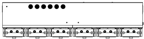
Figure 6. 5-pump unit, bottom view showing wiring holes

Figure 7. L5000Plus Power, Pump Box and TR8000 L Printed Circuit Boards
Parts Identification
- Pump box PCB
- TR8000 L
- Power Supply PCB
- J11, Connections for pumps 1-3
- J12, Connections for pumps 4-6
- J13, Connections for pumps 7 and 8.
- J14, Connection for 24V alarm
- J15, Contact input for low product alarm
- J5 Connection from TR8000 L
- J10, Optional flush manifold input
- Trigger inputs 1-8
- J4, Temperature probe input
- J3, TR8000 L connection to pump box
- J1, Programmer connection
- Switch terminal block, connection to (mains) power supply PCB, 100-240 VAC 50/60 Hz
- Power out to pump box
- Programmer
- Ground wire
Main/Ground Connections (Refer to Figure 7)
- To open the pump box, loosen the screw(s) from lid of the pump box.
- Lift the lid up to open.
- Pull the face plate (containing the pumps) downward so the unit is completely open.
- After cutting mains voltage conduit and stripping the wires, thread the conduit through one of the holes in the bottom of the pump box.
- Connect the mains voltage power to the terminal strip according to label designations, "L" (hot), "N" (neutral).
- Disconnect the yellow, insulated terminal clip, crimp main ground wires to it and then reconnect.
Trigger Signal Connections (TR8000 L) (Refer to Figure 7)

Ensure that the trigger wire voltage and temperature rating are suitable for the application. The current required for the triggers is only 5mA. Wires must be 24-14 AWG.
The TR8000 L is pre-installed inside the pump box, but can be removed for installation within the washer control box or mounted elsewhere inside an approved enclosure.
The TR8000 L serves as the high-voltage interface between the L5000Plus and the washer trigger signals. It also serves as the wiring connection between the programmer and the L5000Plus pump box.
The TR8000 L is prewired with its supply commons (-) looped, or jumpered. If the washer supply common comes from a single circuit, then the common can be connected to any of these. Simply disconnect any one of them and connect the washer supply common.
If your washer supply's commons come from more than one circuit, then you will need to disconnect and reconnect as many as you need.
If the TR8000 L will be removed from pump box and placed on/in washer:

If TR8000 L will be removed from pump box and installed on/in the washer, it must be installed within a regulatory-compliant, electrical-rated enclosure.
- Remove TR8000 L from pump box as shown in Figure 8.

Figure 8. Removing TR8000 L from pump box
- Mount TR8000 L inside of washer, or on its outside using the Velcro strips provided.
- Connect washer power supply trigger wires to TR8000L terminals, using the Figure 10 table as a guide. To open each terminal, press it downward using a screwdriver (see Figure 9). Insert washer power supply wires into terminals.

Figure 9. Using screwdriver to open wire clamp

T8 is not available for triggering pump actions in Formula or Latched Modes. In these modes, T8 is only used for signal monitoring and formula selection.
If TR8000 L will remain in the pump box:
- Thread conduit from washer power source through one of the holes in the bottom of the pump box.
- Connect washer power supply trigger wires to TR8000L terminals, using the Figure table as a guide. To open each terminal, press it downward using a screwdriver (see Figure 9). Insert washer power supply wires into terminals.
Trigger Signal Connections for Relay, Formula, Formula Latched and Sequence Modes
| Trigger Signal | Relay Mode | Formula or Latched Mode with AFS Selected | Formula Latched Mode Using Hot/Cold Fill, AFS not Selected | Sequence Mode | |
| T1 | Pump 1 | T1 | T1 | Drain Signal (manual start) | |
| T2 | Pump 2 | T2 | T2 | Main Wash Cold Trigger | |
| T3 | Pump 3 | T3 | T3 | • | Auto Start Signal |
| T4 | Pump 4 | T4 | T4 | • | |
| T5 | Pump 5 | T5 | T5 | or | |
| T6 | Pump 6 | T6 | T6 | • | |
| T7 | Pump 7 | T7 | T7 | • | |
| T8 | Pump 8 | AFS Timing or not used | T2 | Main Wash Hot Trigger | |
Figure 10. Washer Trigger Signal Connections
Sequence Mode Connection—Manual Start
For standard Sequence Mode installations, connect the drain signal to Trigger 1 (T1+). Pushing the ACTION key will start the sequence.
Sequence Mode Connection—Auto Start
Connect the T1 signal as described for Manual Start. Connect a “start” signal to T3. The “start” signal can be any signal that indicates the start of the wash process, such as the “Machine On” light. With Auto Start, you will not need to press the ACTION key to start the sequence.
Formula Mode Connection
Formula Mode trigger signals usually come from flush hopper solenoid signals or are dedicated supply signals provided by the washer manufacturer. Consult your washer schematic.
Smart Relay Mode Connection
Smart Relay Mode triggers are usually available as dedicated outputs from the washer microprocessor and usually have a single common connection.
Tunnel Automatic Formula Select (TAFS) Mode Connection
Refer to the Figure 11 table to determine trigger connections for desired formulas. For TAFS Mode to work, you must also connect to T7 for the Set Formula Trigger and to T8 for the Batch Transfer Trigger. For a thorough explanation of TAFS Mode, please see the Appendix A and Appendix B in the L5000Plus Programming Guide.
Automatic Formula Selection (for Formula and Latched Modes only)
Same as Formula Mode trigger signals, except that T8 will be monitored and used to select formulas automatically based on programmed trigger timing schemes. See APPENDIX C in the L5000Plus Programming Guide for more information.
Trigger Signal Connections for TAFS Mode
| Formula Number | T1 | T2 | T3 | T4 | T5 |
| No Chem | |||||
| 1 | ON | ||||
| 2 | ON | ||||
| 3 | ON | ON | |||
| 4 | ON | ||||
| 5 | ON | ON | |||
| 6 | ON | ON | |||
| 7 | ON | ON | ON | ||
| 8 | ON | ||||
| 9 | ON | ON | |||
| 10 | ON | ON | |||
| 11 | ON | ON | ON | ||
| 12 | ON | ON | |||
| 13 | ON | ON | ON | ||
| 14 | ON | ON | ON | ||
| 15 | ON | ON | ON | ON | |
| 16 | ON |
Figure 11. Active Trigger Sequences for Each of 16 Formulas
Low Level Alarm Input Wiring (Refer to Figure 7)
The low level alarm switch must supply a contact-closure closed contact when in the depleted state in order to activate the alarm function.

The low-level alarm is a contact-closure type input. Applying any voltage to this input can damage it. When connecting the low-level input, use the connector provided in the parts bag.
Connect low-level switch to LEVEL IN (J15) on the pump box PCB using the connector provided.
Alarm Output Wiring (Refer to Figure 7)
Connect any 24 VDC alarm device to ALARM 24V (J14) on the pump box PCB. When using the audible alarm (code #1200452) mount the alarm in a conduit hole under the unit. Use wire nuts to extend the wires and connect the red wire to ALARM 24V+ and the black wire to ALARM 24V-.

24 VDC alarm output is fuse-limited to 0.5 Amp
Hygiene Temperature Probe Connection
Connect the temperature probe (code #068976) to the Temp Probe input (J4) on the TR8000 L.

- “Temp Probe” input (J4).
Figure 12. TR8000L, Hygiene temperature probe connection
Installing Hygiene Probe in Washer
- Clean the washer's tank wall surface near the bottom of the tank.
- Place heart-shaped adhesive insulating pad over probe.
- Place the flat surface of the probe against the tank wall, below the water line near the bottom of the tank.
- Place heavy-duty tape over the insulating pad to ensure it is well insulated and will not fall off when exposed to moisture and thermal shock.
Auxiliary Pump Box Wiring
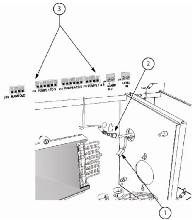
Parts Identification
- Wire harness to be connected to Molex pins on main PCB.
- Grounding wire connection
- Molex pins for pump connections.
Figure 13. Wiring auxiliary pump boxes to main PCB.
- Thread the pump wires through the open terminal in the aux box into the L5000Plus pump box and connect to the appropriate 6-pin Molex connector (J12 for pumps 4-6 or J13 for pumps 7 and 8) on the pump driver (main) PCB.
- Connect the grounding wire from the auxiliary pump box to the ground inside the main pump box as shown in Figure 14.

Figure 14. Auxiliary pump box ground wire connection
- If you install more than one auxiliary box, swap the "closed" terminals with "open" terminal plugs as needed, finishing with the last auxiliary box having a "closed" terminal plug on its right side.
- Use the stickers included in the aux box kit to mark each aux box's pump wires with its pump number.
- When all aux box installation and wiring is complete, use the cable ties included in the kit to tie up any loose wiring.

Do not remove the covers from the motors. A small amount of conductive dust could, over time, come out of the motors and damage the PCB.
Chemical Pump Assignment
- Pump assignment is from left to right. Pump 1 is the leftmost pump and pump 2 is the next pump to its right.
- Smart Relay Mode triggering associates trigger numbers with numerically-corresponding pump numbers; trigger 1 to pump 1, trigger 2 with pump 2, etc.
Programmer Mounting
The L5000Plus programmer is used for programming formula and dosing parameters.
- Using the cable provided, connect the programmer to the programmer icon on the TR8000 L (J1 position).
- If you are using Relay mode, you may disconnect the programmer once programming is complete.
- For all other modes, keep the programmer connected to the TR8000 L and mount it to the front of the washer or other location that allows easy access for operators to change formulas and monitor operation. Use the Velcro provided.

Figure 15. Programmer connected to J1 on TR8000 L.

Beta Technology
2841 Mission Street
Santa Cruz, CA
U.S.A 95060-2142
Customer Service
TEL: 831·426·0882
TEL: 800 • 858 • 2382 (toll-free in U.S.A.)
FAX: 831 · 423 · 4573
FAX: 800 · 221 · 8416
http://www.beta-technology.com
Global Technical Customer Service North America:
TEL: 800 • 468 • 4893 (toll-free in U.S.A)
TEL: 262 • 631 • 4461 (international)
Europe, Middle East & Africa:
TEL: +1 630 · 513 · 9799
Asia Pacific:
TEL +1 86 21-50509900 x 2520
Japan:
TEL: +1 090-6506-5140
Latin America
TEL: +1 - 541148428270
- CONTENTS
- DESCRIPTION PAGE
- SAFETY
- THESE SYMBOLS ON OR INSIDE THE UNIT MEAN
- USE CAUTION TO AVOID PERSONAL INJURY OR DAMAGE TO EQUIPMENT
- CAUTION! RISK OF ELECTRICAL SHOCK
- INSTALLATION STANDARDS
- INTENDED USE/CAPABILITIES
- PARTS IDENTIFICATION
- SPECIFICATION
- PUMP BOX
- PUMP BOX DIMENSIONS (3-PUMP SYSTEM)
- PUMP BOX WEIGHT (3 PUMP SYSTEM)
- MOUNTING (3-PUMP SYSTEM)
- ENCLOSURE MATERIAL
- ELECTRICAL SPECIFICATIONS (PUMP BOX)
- CE COMPLIANT
- SERIES* PUMPS
- TRANSPORT TUBING
- NOMINAL FLOWRATE
- PUMP DISTANCE
- ENVIRONMENTAL SPECIFICATIONS (FOR ALL SYSTEM MODULES)
- ALTITUDE
- INTERNAL AMBIENT TEMPERATURE RANGE
- HUMIDITY
- POLLUTION DEGREE
- INSTALLATION CATEGORY
- RATINGS AND CONFORMANCE (FOR ALL SYSTEM MODULES)
- INSTALLATION PROCEDURE
- WALL MOUNTING
- AUXILIARY PUMP BOXES
- AUXILIARY PUMP BOX MOUNTING INSTRUCTIONS
- CONNECTING TUBING
- SUCTION TUBING
- ELECTRICAL INSTALLATION
- MAIN/GROUND CONNECTIONS (REFER TO FIGURE 7)
- TRIGGER SIGNAL CONNECTIONS (TR8000 L) (REFER TO FIGURE 7)
- IF THE TR8000 L WILL BE REMOVED FROM PUMP BOX AND PLACED ON/IN WASHER
- IF TR8000 L WILL REMAIN IN THE PUMP BOX
- SEQUENCE MODE CONNECTION—MANUAL START
- SEQUENCE MODE CONNECTION—AUTO START
- FORMULA MODE CONNECTION
- SMART RELAY MODE CONNECTION
- TUNNEL AUTOMATIC FORMULA SELECT (TAFS) MODE CONNECTION
- AUTOMATIC FORMULA SELECTION (FOR FORMULA AND LATCHED MODES ONLY)
- LOW LEVEL ALARM INPUT WIRING (REFER TO FIGURE 7)
- ALARM OUTPUT WIRING (REFER TO FIGURE 7)
- HYGIENE TEMPERATURE PROBE CONNECTION
- INSTALLING HYGIENE PROBE IN WASHER
- CHEMICAL PUMP ASSIGNMENT
- PROGRAMMER MOUNTING
Brand : Coburn
Model : L5000Plus
Category : Dosing pump