InterPuls IUC 24 - Industrial Controller Coburn - Free user manual and instructions
Find the device manual for free InterPuls IUC 24 Coburn in PDF.


| Brand | InterPuls |
| Model | IUC 24 |
| Product type | Electronic pulsation controller for milking machines |
| Power supply | 24 VDC |
| Display | LCD screen with adjustable contrast |
| Keypad | Navigation and configuration keys (Menu, Set, arrows) |
| Number of parameter sets | 2 (Set 1 and Set 2) |
| Programmable parameters | Frequency, front/rear ratio, phase, inversion |
| Hour meter | Integrated operating hours counter |
| Maintenance scheduling | Scheduled maintenance alert (next service) |
| Pulsator voltage | Display of pulsator control voltage |
| Output current | Display of current delivered to pulsators |
| Software version | Display of software version |
| Factory settings | Reset to default values |
| Language | Selectable display language |
| Mounting | Wall mounting with protective cover |
| Dimensions (approx.) | 200 x 150 x 80 mm |
| Weight (approx.) | 0.8 kg |
| Maintenance | Clean with a soft cloth; periodic check of electrical connections |
| Safety | Safety and fire protection instructions in accordance with standards |
| Spare parts | Available from the manufacturer (InterPuls S.p.A.) |
| General information | Provided user and installation manual (ref. 1040195_MI) |
Frequently Asked Questions - InterPuls IUC 24 Coburn
User questions about InterPuls IUC 24 Coburn
0 question about this device. Answer the ones you know or ask your own.
Ask a new question about this device
Download the instructions for your Industrial Controller in PDF format for free! Find your manual InterPuls IUC 24 - Coburn and take your electronic device back in hand. On this page are published all the documents necessary for the use of your device. InterPuls IUC 24 by Coburn.
USER MANUAL InterPuls IUC 24 Coburn
User Guide & Owner Manual
InterPuls IUC 24


Part of your business
InterPuls®
InterPuls S.p.A.
Via F. Maritano, 11 - 42020 - Albinea (RE) – ITALY
Tel. +39 0522 347511
Fax +39 0522 348516
sales@interpuls.com
| MANUFACTURER | InterPuls S.p.A |
| ADDRESS & CONTACT DETAILS | Address: F. Maritano, 1142020 - Albinea (RE)ITALYTel. +39 0522 347 511Fax +39 0522 348 516Website: www.interpuls.comE-mail: sales@interpuls.com |
| TYPE OF DOCUMENT | User Guide & Owner Manual |
| DOCUMENT REF. CODE | 1040195_MI_00.05.11 - IT |
| EDITION | Rev.00.05.2011 |
| PRODUCT MODEL | InterPuls IUC 24 |
| YEAR OF MANUFACTURE | 2011 |
INDEX
- GENERAL GUIDANCE AND SECURITY WARNINGS....3
- BEFORE USING THE PRODUCT 4
- ASSEMBLY, DISMANTLING AND START-UP 4
- DISPOSAL 4
- FIRE SAFETY 5
- REFERENCES OF APPLIED LAWS 5
- BRANDING......5
- WARNING SIGNS....6
- DESCRIPTION OF DEVICE 7
- TECHNICAL CHARACTERISTICS....7
10.1. Power supply 8
10.2. Controls 8
10.3. Programmable parameters ...... 9
10.4. Visible parameters....9
10.5. Range of values.... 10
10.6. Keypad 10
- CONNECTION AND INSTALLATION.... 11
11.1. Wall mounting of control box 11
11.2. Cover opening 12
11.3. Control box without protective cover 13
11.4. Electrical connections.... 14
11.5. General connection diaram.... 15
11.6. Adjustment of screen contrast 15
11.7. Cover assembly.... 16
- IUC 24 MENU FEATURES.... 16
12.1. Menu 1.1 & Menu 1.2 – Setup Pulsation Parameters SET1 and SET2...... 18
12.1.1 Setup Pulsation Frequency (FREQ.).... 18
12.1.2 Front Ratio Setup (RATIOF) 18
12.1.3 Rear Ratio Setup (RATIOR).... 19
12.1.4 Phase Setup (PHASE).... 19
12.1.5 Reverse Setup (REVERSE).... 20
12.2. Menu 1.3 – Operating Hours Counter 22
12.2.1 Viewing Running Hours.... 22
12.2.2 Next maintenance setup 23
12.3. Menu 1.4 – Pulsators Current Voltage 24
12.4. Menu 1.5 – Current Supplied ...... 24
12.5. Menu 1.6 – Software Version.... 25
12.6. Menu 1.7 – Resetting Default Values.... 25
12.7. Menu 1.8 – Setting the Language.... 25
-
MAP OF THE MENUS....26
-
SWITCHING ON FOR THE FIRST TIME 29
-
SWITCHING ON AFTER THE FIRST TIME 30
-
TROUBLESHOOTING AND ALERTS 31
16.1. No command to pulsators.... 31
16.2. Excessive current 32
16.3. Memory error 33
16.4. Service control time exceeded 33
16.5. Low pulsator command voltage 34
-
MAINTENANCE....34
-
DRILLING TEMPLATE 34
1. GENERAL GUIDANCE AND SECURITY WARNINGS
| Important instructions | To ensure the safety of the operators and to avoid possible damage to the machinery, it is essential to acknowledge what is outlined in this instruction manual before performing any activities. |
| Symbols used in the manual | The following symbols will be used in this manual to highlight instructions and warnings which are particularly important:  ATTENTIONThis symbol indicates accident prevention methods for operators and/or other people at risk. ATTENTIONThis symbol indicates accident prevention methods for operators and/or other people at risk.  WARNINGThis symbol indicates the possible damages which can be caused to the machinery and/or the component parts. WARNINGThis symbol indicates the possible damages which can be caused to the machinery and/or the component parts.  NOTEThis symbol indicates useful information. NOTEThis symbol indicates useful information. |
| Rules of usage |  ATTENTIONNon-compliance with the warnings presented in this manual can lead to the malfunctioning of the machinery or damage to the system. ATTENTIONNon-compliance with the warnings presented in this manual can lead to the malfunctioning of the machinery or damage to the system. |
| Disclaimer | InterPuls S.p.A. denies any liability for damages caused to persons, animals or objects through the misuse of the machinery. |
2. BEFORE USING THE PRODUCT
Rules and requirements for authorised staff

ATTENTION
Before using the device, the operator must carefully read the manual.
- The device must be used by people over the age of 18, who have been trained, are physically and mentally fit and have been given appropriate information relating to how it operates.
- During the assembly and activation of the device, the instructions provided in the manual, the norms and rules relating to safety in the workplace and health safety must be followed.
- The equipment satisfies the legal requirements and relative technical standard regarding safety and hygiene in the workplace, as well as environmental and fire safety measures.
3. ASSEMBLY, DISMANTLING AND START-UP
Warnings for assembly
The installation must be carried out by qualified staff in-line with the laws in force.
The power cable must satisfy the requirements foreseen by the laws in force.
The electrostatic chargers of all fixed conductors must be replace with ground cables.
The main circuit breaker must be installed next to the milking room and must foresee a blocking option in the disconnection position.

ATTENTION
Always disconnect the equipment from the power supply before carrying out maintenance, cleaning or repair works.
4. DISPOSAL
General rules
The device must only be disposed of by authorised companies in-line with the laws and rules foreseen.
The packaging must be delivered to the specified companies authorised to recycle.
5. FIRE SAFETY
Preliminary remark

NOTE:
The device does not include a fire extinguisher.
The operator must ensure that the installation location is equipped with an adequate number of suitable fire extinguishers, placed where they are visible and protected from any damage or improper use.
Safety rules

ATTENTION
It is absolutely forbidden to extinguish electrical fires with water!
Fire extinguisher characteristics
Only use dry powder, carbon dioxide or halon fire extinguishers. These will need to be located alongside the device.
Authorised staff will need to receive instructions regarding how they work.
6. REFERENCES OF APPLIED LAWS
- Direttiva CE n. 2006/095 (Relating to electrical safety (LVD))
- Direttiva CE n. 2004/108 (Relating to electromagnetic compatibility (EMC)
7. BRANDING
Label applied to the device
InterPuls
Via Maritano 11, 42020 ALBINEA (RE) ITALY
PULSATION CONTROLLER
MODEL: IUC24
SERIAL NUMBER: 10405113749
ELECTRICAL SPECIFICATIONS:
INPUT: 100-265 Vac 50/60 Hz
3,5A @ 115 Vac 1,7A @ 230 Vac
OUTPUT: 24Vcc 8,4A max @ 25°C
N° PULSAT, TOT MODEL LE: 24 MAX N° PULSAT, x CAN, MODEL LE: 6 MAX

CODE 104 0183-00
Figure 1
8. WARNING SIGNS
Signs displayed on the device

Figure 2

ATTENTION REMOVE POWER
Before opening the cover the IUC 24 must be disconnected from the electricity network.

ATTENTION
Damage or removal of the warning signs is absolutely forbidden.
9. DESCRIPTION OF DEVICE
General characteristics
The IUC 24 InterPuls is a control box equipped with a switching transformer used to supply power to the electrical pulsator with a 24 Vcc 8.4 A output at a maximum of 25°C.
It is capable of supplying power to a maximum of 24 pulsators (Front & Rear) divided in 4 channels (maximum of 6 pulsators per channel).
Every pulsator is equipped with two coils: one Rear and one Front controlled by duty-cycles programmable within a 10÷90 (90÷10) range and with a programmable frequency of between 30 and 260 pulsations/minute.
Maximum absorption of every coil: 3.6W at 24Vcc (absorption approximately 150mAcc).
Every channel must supply a maximum nominal of 1.8A (two coils simultaneously for 6 pulsators) and has a maximum power supply limit set by the controlling CPU of approximately 2.0A +10% -0%.
The device uses the classic switching technology and therefore absorbs the current with almost unitary power as per the norms in force in Europe (EN61000 and derivatives), United States and/or Japan (ex IEC555)
• Rapid response to rate of loading
- Reduced dimensions
The convertor is carried out at high frequency to reduce electrical component and packaging waste.
10. TECHNICAL CHARACTERISTICS
| Model | InterPuls IUC 24 |
| Software version | 2.5 |
| Entry voltage | From 100 to 265 Vac |
| Frequency | 50-60 Hz |
| Electrical output at work space extremities | >80% |
| Power supply for Pulsator with exit | 24Vcc 8,4A max at 25°C |
| Max N° of powerable Pulsators | 24 |
| Programmable pulsation frequency | From 30 to 260 ppm |
| Max absorption per coil | 3,6W at 24Vcc (≈ 150mAcc) |
| Average absorption per coil | 3,2W at 24Vcc |
| Dimensions (LxWxH) | 370 x 265 x 145 mm |
When switched on the first line of the screen reads “Interpuls” and the second displays the software version installed.
10.1. Power supply
| Power supply | 100÷265Vac 50/60Hz with filter for standard interferences |
| Current absorption | 3,5A @ 115Vac 1,7A @ 230Vac |
| Network connection | Three-pole connector with screw terminals (included) |
| Fuses on the network | Two 6.3A (T) |
| Exit voltage | 24Vcc @ 8,4A max (see Mean-Well power supply characteristics SP200-24) |
| Pulsator connection | The pulsators are connected via three terminals for each FCR channel |

NOTE: The power supply does not require an adaptor transformer.
10.2. Controls
Fire extinguisher characteristics
Only use dry powder, carbon dioxide or halon fire extinguishers. These will need to be located alongside the device.
Authorised staff will need to receive instructions regarding how they work.
Settings selectable by the user
Change settings and check correct operation of the power supply/pulsator via the screen and the keys on the cover.
Select group options SET1 and SET2 via remote control (optional).
10.3. Programmable parameters
Pulsation parameters
IUC 24 allows the following pulsator parameters to be set to operate pulsators not equipped with programmable boards (e.g. InterPuls LE):
• FREQ.: pulsation frequency
• RATIO: power current rate between Front and Rear channel
- PHASE: phase displacement of power current “cascaded” via the groups of pulsators
- REVERSE: activation of reverse ON and OFF timings of the pulsator coils

NOTE: For the programming options refer to CHAPTER 12 Par. 1.1 – 1.5.
Other programmable parameters
- COUNTER: setting of number of operating hours before next periodic check

NOTE: For the programming options refer to CHAPTER 12 Par. 2
• LANGUAGE: setting of the menu language

NOTE: For the programming options refer to CHAPTER 11 Par. 7
10.4. Visible parameters
Visible parameters
VOLTAGE: view the voltage supplied to the pulsators
NOTE: For the programming options refer to CHAPTER 11 – Par. 3
- CURRENT: view power current absorbed on each channel by the pulsators


NOTE: For the programming options refer to CHAPTER 11 – Par. 4
10.5. Range of values
| SET1 & SET2 | ||
| Parameter | Default settings | Selectable values |
| FREQ. | 60 | 30÷260 Pulsations/minute |
| RATIOF | 60-40 | 10-90 ÷ 90-10 Front |
| RATIOR | 60-40 | 10-90 ÷ 90-10 Rear |
| PHASE | T/4 | T - T/2 - T/3 - T/4 - T/5 - T/6 - T/7 - T/8 |
| REVERSE | OFF | ON / OFF |
| TIMER | ||
| Parameter | Default settings | Selectable values |
| SERVICE | 5000 | 0÷9999 hrs |
| LANGUAGE | ||
| Parameter | Default settings | Selectable values |
| LANGUAGE | ENGLISH | ITALIANO - ENGLISH - DEUTSCH - FRANCAIS - ESPANOL |
10.6. Keypad
Keypad layout
The keypad is equipped with 5 keys:

Key features
The keys allow you to:


Scroll menus/parameter modifications


Modify/confirm
Selection of parameter set 1 or 2 (hold down for 3 seconds)
11. CONNECTION AND INSTALLATION
11.1. Wall mounting of control box
Assembly system
The control box can be wall mounted or fixed to an appropriate support using screws.

Figure 3

NOTE: Screws are not supplied

NOTE: At the end of the manual you can find:
- The drilling template for the support
- The measurement of the distance between the fastening holes
11.2. Cover opening
Cover opening
To remove the cover unscrew the 6 screws positioned on the side of the cover.

Figure 4

WARNING TURN OFF CURRENT
Before opening the cover for the IUC 24 must be removed from the power supply.

WARNING
Do not completely remove the screws from the cover.
The length of the screws allows the cover to be removed without them being unscrewed completely.
Cover removal
Remove cover as shown taking care not to touch any of the components inside the control box.

Figure 5
11.3. Control box without protective cover
Control box layout

Figure 6

Figure 7
1 – Switching current for pulsator channels
5 – Cable glands for pulsator channels
2 – Pulsator control board
6 – Cable gland for network channels
3 – Control unit
7 – Fuse holders
4 – Network entry board
8 - Switch

ATTENTION
The upper board is fixed to spring supports which allow it to be correctly positioned in relation to the cover. The four springs inside the small nylon columns MUST NOT be removed.

ATTENTION
The small nylon columns are comprised of two parts which contain a spring. If due to a hard knock these parts become separated be careful not to lose either part.

ATTENTION
If the small nylon columns are accidentally dismantled to remount the upper board do as follows:
- Check that there is a spring in each column.
- Put every part of the small column in place ensuring the guides match.
- Press the parts of the small columns which jut out from the upper board.
11.4. Electrical connections
Preliminary remark
To complete the connection:
- of the control box power cable
- of the cables which control the pulsators
the cover of the control box must be removed.

ATTENTION REMOVE POWER
Before removing the cover the power supply to the IUC 24 must be removed.
Connection of control box power cable
Connect the power cable of the electricity network to the CN2 separable connector (three-poles) respecting the connections as detailed below in the diagram:

Figure 8

ATTENTION
The equipment must be connected to the electrical network in-line with the laws in force: InterPuls does not guarantee the correct operation of the device if connected to networks with unstable voltage and frequency.

ATTENTION
Size the power cable in-line with the laws in force and the absorption as detailed on the IUC 24 label.
Connection of pulsator control cables
Connect the pulsator control cables to the respective terminals in groups of 6 pulsators per channel.
Connect the cables of the first 6 pulsators to terminal “Channel 1” respecting the F-C-R indications.
Connect the cables of the next 6 pulsators to terminal “Channel 2” and so on for “Channel 3” and “Channel 4”.

Figure 9
11.5. General connection diagram
General connection layout

Figure 10
11.6. Adjustment of screen contrast
Regulation procedure
To adjust the contrast of the screen rotate the knob located on the display board:

Figure 11

ATTENTION
The contrast of the screen has been set by the production house to provide optimum performance.
The contrast must be adjusted only when the control box is viewed from specific angles. Only touch the adjustment knob if the screen is not very legible.

ATTENTION
Carefully twist the contrast adjustment knobs.
11.7. Cover assembly
Cover assembly procedure
Ensure the screws are sufficiently distanced from the support to ensure the edge of the cover can slot through.

Figure 12
Lay down the rear edge of the cover on the 4 screws positioned on the rear part of the support, taking care not to damage the components and the cables enclosed within the control box.
Slide the cover on the rear screws until the screws fixed to the base slot in. Lightly push the cover so that the rear screws also slot in.
Whilst maintaining a light pressure on the cover tighten the 6 screws, ensuring the cover is securely fixed but without excessively tightening the screws.

Figure 13

Figure 14

Figure 15
12. IUC 24 MENU FEATURES
Preliminary remark
From the menu it is possible to change the pulsation parameters of the control box and other various operations described in this manual.
Continued...
Procedure for accessing main menu
To access the control box main menu it is necessary to:
- Switch on the control box
- Wait for the equipment to display the channel functionality data indicating standby mode



- Press the key and insert the password 1 3 2
- Select the first number (1) using the

to confirm
- Repeat the operation to insert the second number (3)
- Repeat the operation to insert the third number (2)

and keys and press

keys and press

NOTE: Settings left incomplete for more than 15 seconds will be cancelled.
- If the password inserted is correct the word "CORRECT" appears on screen for 3 seconds
- After a short while the first page of the main menu, MENU 1.1. SETUP
SET1, appears on screen

- Pressing allows you to move to next menu whilst pressing allows you to access the page to adjust the SET1 parameters

Complete menu structure
For the complete menu structure refer to CHAPTER 13.
| MENU | FEATURE |
| MENU 1.1SETUP SET 1 | SETUP parameters of SET1 |
| MENU 1.2SETUP SET 2 | SETUP parameters of SET2 |
| MENU 1.3TIMER | View/set the counter operating hours (password protected) |
| MENU 1.4VOLTAGE | View the voltage of the pulsators |
| MENU 1.5CURRENT | View the current absorbed by the pulsators divided by channel |
| MENU 1.6VER SOFTWARE | Displays software version |
| MENU 1.7DEFAULT | Reset SET1 and SET2 default parameters (password protected) |
| MENU 1.8LANGUAGE | Language selection |
12.1. Menu 1.1 & Menu 1.2 – Setup Pulsation Parameters SET1 and SET2
12.1.1 Setup Pulsation Frequency (FREQ.)
Parameter adjustment procedure
- Enter Menu 1.1 SETUP SET1
- Scroll the parameters until the FREQ page is displayed
SETUP SET 1 RATE 60 - Press to adjust the pulsation frequency specified in ppm (pulsations per minute)
- An arrow will appear on screen to highlight that the data is in adjustment
mode SETUP SET 1 RATE -> 60


- Press or to adjust the value and press to confirm. The arrow indicating adjustment mode will disappear


NOTE: The setting is the same for all 4 channels.

- Press to move to the next screen to adjust the Front Ratio (RATIOF)
12.1.2 Front Ratio Setup (RATIOF)
Parameter adjustment procedure
- Enter Menu 1.1 SETUP SET1, scroll the parameters until the RATIO F page is displayed SETUP SET 1 RATIO F 60/40

- Press to adjust the Front Ratio. An arrow will appear on screen to SETUP SET 1 RATIO F -> 60/40 highlight that the data is in adjustment mode
SETUP SET 1 RATIO F -> 60/40

- Press or to adjust the value and press to confirm. The arrow indicating adjustment mode will disappear


NOTE: The setting is the same for all 4 channels.

NOTA: When the RATIO F value is set the same value is automatically set for the RATIO R parameter so that both values are identical. In the instance different values for RATIO F and RATIO R are required, set the desired RATIO F value first and subsequently the RATIO R value as explained hereafter.

- Press to move to the next screen to adjust the Rear Ratio (RATIO R).
12.1.3 Rear Ratio Setup (RATIOR)
Parameter adjustment procedure
- Once in Menu 1.1 SETUP SET1, scroll the parameters until the RATIOR
setup SET 1 RATIO R 60/40 page is displayed

- Press to adjust the Rear Ratio. An arrow will appear on screen to
highlight that the data is in adjustment mode SETUP SET 1 RATIO R -> 60/40

- Press or to set a RATIO R value different to the one set for RATIO F
- Once the value is set press to confirm. The arrow indicating adjustment mode will disappear

NOTE: In the instance you want to set the same value for RATIO F and RATIO R only adjust the RATIO F option.

- Press to move to the next screen to adjust the Phase (PHASE)
12.1.4 Phase Setup (PHASE)
Preliminary remark
By adjusting the PHASE parameter it is possible to set a phase displacement between the pulsation phases of the various groups of the system.
This phase displacement ensures fewer vacuum fluctuations in the milking system.

NOTE: Defined as “T” the time of a complete pulsation cycle expressed in milliseconds, the phase displacement “delay” between the wave forms of the four IUC 24 channels is equal to the value indicated on screen.
60/40 ratio, cycle duration 1000Ms
The diagram represents a T/2 setting (500Ms delay between each channel)
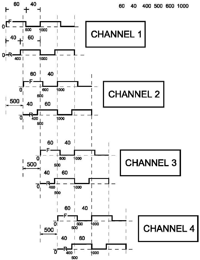
Figure 16
[CHANNEL 1 / CHANNEL 2 / CHANNEL 3 / CHANNEL 4]
Phase setup procedure
- Enter Menu 1.1 SETUP SET1, scroll the parameters until the PHASE

- Press ← to adjust the phase value. Each time the ← key is pressed the set value moves to the following one (T,T/2,...,T/7,T/8)
- Press (REVERSE) to move to the next screen to activate the reverse
12.1.5 Reverse Setup (REVERSE)
Preliminary remark
This feature activates the reversal of the ON and OFF timings of the pulsator coils.

NOTE: If a 60/40 ratio is set in the RATIOF menu and if the REVERSE function is set to ON, an output ratio of 40/60 is obtained.
- Enter the Menu 1.1 SETUP SET1, scroll the parameters until the
SETUP SET 1 REVERSE OFF
REVERSE
page is displayed

Press to switch the reverse parameter from OFF to ON.

NOTE : The control unit normally operates with the REVERSE parameter set at OFF.

NOTE : The REVERSE ON condition is highlighted by the appearance of the letter "R" on the first line of the display, in the top right hand corner (last character)
C1 RATE 60 PPM R F 60/40 R 60/40
Pulsator power supply diagram in Normal condition (REVERSE OFF)

Figure 17
Pulsator power supply diagram in Reverse condition (REVERSE ON)

Figure 18
12.2. Menu 1.3 – Operating Hours Counter
Preliminary remark
The IUC 24 control box can count and log the operating house of the device.
SERVICE TIME OVERDUE
It is possible to set a time after which a message TIME OVERDUE is displayed, along with an intermittent alarm signal to inform the operator that the maintenance staff must be contacted to carry out the periodic check.
Counter setup procedure
- Select the MENU 1.3 TIMER page from the main menu

- Press to access the parameters of this menu and insert the technical assistance password
- If the password inserted is correct "VALID" appears on screen for 3 seconds and the first submenu appears

NOTE: Settings left incomplete for more than 15 seconds will be cancelled.

NOTE: The IUC 24 control box is protected by 2 passwords. The first password, 1 3 2, provides access to the main menu from which it is possible to adjust the pulsator parameters. The second password allows operations, reserved to expert staff, to be carried out.
12.2.1 Viewing Running Hours
Preliminary remark
The hours since the last reset are indicated in the upper part of the screen
ELAPSED 0h ENTER TO RESET
Zeroing hours procedure
To zero the running hours counter do as follows:
- Press the key
- Confirm the operation pressing the key again - The screen will display a message confirming the operation is complete
WORKING HOURS RESETTED
- Press the ↑ key to move to the next submenu
12.2.2 Next maintenance setup
Preliminary remark
The screen displays the number of hours currently set between the reset (see
12.2.1.) and the next periodic check alert
SERVICE 5000 HOURS
Adjustment of set value procedure
- Press the key. On the second line of the screen the first number of
the hours currently set appears (thousands).
5
SERVICE


- Press or to select a different value and the key to confirm
- On the second line of the screen the second number of the hours
SERVICE currently set (hundreds) will appear 50
50

- Press or to select a different value and the key to confirm
- On the second line of the screen the third number of the hours currently
set (tens) will appear
500
SERVICE

- Press or to select a different value and the key to confirm
- On the second line of the screen the fourth and final number of the hours
currently set will appear
SERVICE 5 0 0 0

- Press or to select a different value and the key to confirm
- The screen now indicates the new number of hours set before the next
periodic check alert
SERVICE 5000 HOURS

NOTE: Settings left incomplete for more than 15 seconds be cancelled.

NOTE: The default value is 5000 hours.

NOTE: The maximum number of hours selectable is 9999.
12.3. Menu 1.4 – Pulsators Current Voltage
Preliminary remark
The IUC 24 control unit allows the current voltage supplied to the pulsators to be viewed.
Viewing procedure
- Select the MENU 1.4 VOLTAGE page from the main menu
- On the second line of the screen the voltage value currently delivered to
the pulsator is displayed

12.4. Menu 1.5 – Current Supplied
Preliminary remark
The IUC24 control box allows the current supplied to the pulsators to be viewed.
Viewing procedure

to enter
- On screen the current supplied by the Front and Rear terminal of the
control box's channel C1 will be displayed

- The first line specifies the channel to which the data displayed refers to
- On the second line of the screen the value of current supplied by the C1 Front terminal to the left and by the C1 Rear terminal to the right will be displayed
- Wait 10 seconds to view the data relating to channels C2, C3 and C4 in sequence, otherwise select the channel you wish to view by pressing the

and keys

NOTE: Current less than 40mA appear as absent load and the screen display indicates 0.00A.

NOTE: Indication of an absorbed current equal to 0.4A on a powerless channel is normal and is due to the test current (non-influential on the correct functioning of the control box).

NOTE: The maximum current deliverable by every Front/Rear connector before the circuit breaks is 2.0A.

NOTE: The intermittent “SHORT CIRCUIT” alert appears on screen when there is a surcharge on one channel of the control box; it is interrupted when on the “MENU 1.5 CURRENT” page. The control box nevertheless limits the current and this alert reappears upon exiting the menu.
12.5. Menu 1.6 – Software Version
Viewing procedure
When the Main Menu page entitled MENU 1.6 VER SOFTWARE is selected, the second line of the display will show the software version installed in the device.
MENU 1.6 SOFTWARE REL 2.5
12.6. Menu 1.7 – Resetting Default Values
Preliminary remark
It is possible to reset all the SET1 and SET2 parameters to their default values.
Default value resetting procedure
- Select the Main Menu page entitled MENU 1.7 DEFAULT

- Press to access the parameters of this menu and enter the password for technical support.

NOTE : If the settings are left incomplete for more than 15 seconds the function in course will be cancelled.

NOTE : The IUC24 control unit is protected by 2 passwords. The first password 1 3 2 is the one that enables access to the Main Menu from which the pulsation parameters can be edited. The second password allows operations reserved to specialised personnel to be carried out.
- If the password entered is correct, within 3 seconds the word "VALID" will
appear, followed by the message
DEFAULT SET1-2 RESTORED
- At the end of the resetting process, the control unit repositions itself on the Main Menu page entitled MENU 1.7 DEFAULT.
12.7. Menu 1.8 – Setting the Language
Preliminary remark
The following languages can set: ITALIAN - ENGLISH - GERMAN - FRENCH - SPANISH
Language setting procedure
- Select the Main Menu page entitled MENU 1.8 LANGUAGE

- Press to access.

Continue...


- Press
Press
or
to select the desired language

to confirm.

NOTE : Once the desired language has been selected, the control unit turns to the Main Menu page entitled MENU 1.8 and all the pages of the menu now displayed in the chosen language.
13. MAP OF THE MENUS
GENERAL TREEVIEW

Figure 19
Menu 1.1 SET 1

Figure 20
Menu 1.2 SET 2

Figure 21
Menu 1.3 TIMER

Figure 22
Menu 1.5 CURRENT

Figure 23
Menu 1.7 DEFAULT

Figure 24
Menu 1.8 LANGUAGE
All the menu's options are displayed in the chosen language

Figure 25
14. SWITCHING ON FOR THE FIRST TIME
First time procedure

WARNING
Before switching on, ensure that all the connections have been correctly installed as indicated in the paragraph - Errore. L'origine riferimento non è stata trovata.
- Switch the device on by turning the main switch on the control unit to the ON position.
Cont...

Figure 26
- Wait until the control unit starts up and enters its normal operation cycle.
The following data are displayed
C1 RATE 60 PPM F 60/40 R 60/40
Menu
- Press the button and enter the password 1 3 2.
- Set the pulsation parameters as explained in paragraph 12.1 - Menu 1.1 & Menu 1.2 - Setup Pulsation Parameters SET1 and SET2 Pulsation Parameters.
- Once the pulsation parameters have been successfully set, press the
Menu
button until
the
stand-by
screen
returns
C1 RATE 60 PPM F60/40 R 60/40 II
- All the settings programmed are stored, even when the power supply is cut off.
15. SWITCHING ON AFTER THE FIRST TIME
Switching on after the first time
- Turn the switch on.
- For 20 seconds, the control unit shows the software version stored in the memory.
- The currently set pulsation parameters are loaded. This time prior to the starting of the pulsators allows optimum vacuum to be obtained in the system before the pulsators start up.
DATA RESTORED FROM EEPROM
- The message FROM EEPROM indicates that the control unit has loaded the set parameters correctly and that it will start up with the last set of parameters selected.
- Pulsation then starts up and the following message is displayed
C1 RATE 60 PPM F 60/40 R 60/40 I
- The alternating flashing of the two bars in the bottom right hand corner of the display indicates that the microprocessor is controlling the power transistor of the pulsators correctly.
- The message is displayed for 10 seconds on each channel and is repeated cyclically
Cont...


- By pressing the 📄 or 📋 button, it is possible to display the information relative to a specific channel, without having to wait for the automatic scrolling.
- In order to switch from the settings stored for SET1 to those stored for
SET2, hold down the
Set 1/2
button for at least 3 seconds.

NOTE : It is possible to switch from SET1 to SET2 both during the normal operation of the control unit and also from the programming menu.
- The SET1 and SET2 LEDs indicate which of the two sets of parameters is currently active.

NOTE : If the set is switched during the normal operation of the control, the display is immediately updated with the new pulsation parameters.

NOTE : When the control unit is switched on, the device starts operating in the last SET of parameters selected prior to being switched off and it reserves all the data programmed before it was switched off.
16. TROUBLESHOOTING AND ALERTS
16.1. No command to pulsators
| Problem Encountered |
| No command to the pulsators; no pulsation on some of the pulsator channels |
| Checks to be performed |
| During the Stand-by condition, failure of one of the two flashing bars indicates a pulsator channel power failure. |
| Solutions |
| Contact Service immediately. A part of the system may not be receiving the pulsation command. |
16.2. Excessive current
| Problem Encountered |
| No command to the pulsators; no pulsation on some of the pulsator channels. |
| Checks to be performed |
During operation, the normal Stand-by screen alternates with another indicating “SHORT CIRCUIT”.This happens when the current of a single section (F or R) of a channel exceeds the limit of 2.0A. The second line of the display shows which section of which channel is in overload condition (e.g.: F1=Front Channel 1, R4=Rear Channel 4). This channel is isolated from the load, i.e. it is no longer powered while all the other sections continue to work normally. Channel 1 F in overload or short circuit condition.If several overload/short circuit conditions occur at the same time, the control unit reacts by interrupting the pulsation command only on the channels affected by the problem and a message is displayed indicating which channels are affected by the failure. Channel 1 F in overload or short circuit condition.If several overload/short circuit conditions occur at the same time, the control unit reacts by interrupting the pulsation command only on the channels affected by the problem and a message is displayed indicating which channels are affected by the failure. Channels 1, 3, 4 coil R in overload or short circuit condition.The control unit automatically eliminates the pulsation command in the faulty part of the system only.If the damage is temporary, the situation returns to normal and the message disappears; otherwise, the channel remains disabled until the control unit is switched off and then switched on again. Channels 1, 3, 4 coil R in overload or short circuit condition.The control unit automatically eliminates the pulsation command in the faulty part of the system only.If the damage is temporary, the situation returns to normal and the message disappears; otherwise, the channel remains disabled until the control unit is switched off and then switched on again. |
| Solutions |
Contact Service without delay. Do not use the channels affected by the problem for milking.There might be a problem in the electrical connections between the pulsators and the control unit.[DOWA]NOTE: The excess load condition can be maintained indefinitely without damage because the power transistors that feed the pulsators are protected against permanent short circuit. NOTE: The control unit verifies the short circuit or overload condition by attempting to restore the power supply to the pulsators 3 times at 6-second intervals. If, after the third attempt, the failure persists, the power supply is cut off until the control unit has been switched off and then switched on again. NOTE: The control unit verifies the short circuit or overload condition by attempting to restore the power supply to the pulsators 3 times at 6-second intervals. If, after the third attempt, the failure persists, the power supply is cut off until the control unit has been switched off and then switched on again. NOTE: The SHORT CIRCUIT message is associated with an intermittent buzzer.NOTE: In the event of multiple alarms, the message SHORT CIRCUIT alternates with the reporting of the other currently active alarms (WARNING LOW VOLTAGE and/or OPERATING HOURS TECHNICAL SUPPORT) NOTE: The SHORT CIRCUIT message is associated with an intermittent buzzer.NOTE: In the event of multiple alarms, the message SHORT CIRCUIT alternates with the reporting of the other currently active alarms (WARNING LOW VOLTAGE and/or OPERATING HOURS TECHNICAL SUPPORT) |
16.3. Memory error
| Problem Encountered | |
| The control unit is not operating correctly and one of the following messages is displayed: | |
| NO DATA SAVEDIN EEPROM MEMORY | EEPROMERROR |
| Checks to be performed | |
| Switch off the control unit and wait for 30 seconds before switching it on again. Check whether the error message is still displayed. | |
| Solutions | |
| Contact Service without delay.The message indicates the existence of errors in the memory of the control unit. These errors cancel the settings saved and delete the service hours stored by the machine. | |
16.4. Service control time exceeded
| Problem Encountered |
| The control unit displays the following message:SERVICETIME OVERDUEThe message displayed is associated with an intermittent buzzer (0.5sec ON - 2sec OFF) |
| Checks to be performed |
| Ensure that, after 10 seconds, the display starts showing the operating parameters again. |
| Solutions |
| Contact Service immediately.When the operating time of the control unit exceeds the number of hours set for the next periodical check (default=5000 hours), each time the control unit is switched on a message will appear for 10 seconds reminding the operator to call Service for the periodical check of the equipment.NOTE: Only Service can cancel the alarm message by entering – by means of the appropriate password – the Menu 1.3 Timer |
16.5. Low pulsator command voltage
| Problem Encountered |
| The control unit displays the following message:WARNINGLOW VOLTAGEThis message alternates on the display with the normal message indicating that pulsator control is in operation (2sec ON - 10sec OFF) |
| Solutions |
| Contact Service immediately.The output voltage of the power supply unit requires adjustment.The microprocessor control works well even with very low voltages but some pulsators might NOT work properly with command voltages that are too low. An alarm signal sounds when the supply voltage of the pulsator drops below 21V. |
17. MAINTENANCE
Checks to be performed
A specialised technician's visit is recommended for maintenance every 12 months in order to check the state of wear of the electrical and mechanical components of the Programming system
18. DRILLING TEMPLATE
Cont...
φ10,500

250
- USER GUIDE & OWNER MANUAL
- PART OF YOUR BUSINESS
- INTERPULS®
- INDEX
- GENERAL GUIDANCE AND SECURITY WARNINGS
- BEFORE USING THE PRODUCT
- ATTENTION
- ASSEMBLY, DISMANTLING AND START-UP
- DISPOSAL
- FIRE SAFETY
- PRELIMINARY REMARK
- NOTE
- SAFETY RULES
- FIRE EXTINGUISHER CHARACTERISTICS
- REFERENCES OF APPLIED LAWS
- BRANDING
- LABEL APPLIED TO THE DEVICE
- INTERPULS
- WARNING SIGNS
- ATTENTION REMOVE POWER
- DESCRIPTION OF DEVICE
- GENERAL CHARACTERISTICS
- TECHNICAL CHARACTERISTICS
- POWER SUPPLY
- CONTROLS
- PROGRAMMABLE PARAMETERS
- PULSATION PARAMETERS
- OTHER PROGRAMMABLE PARAMETERS
- VISIBLE PARAMETERS
- RANGE OF VALUES
- KEYPAD
- KEYPAD LAYOUT
- KEY FEATURES
- CONNECTION AND INSTALLATION
- WALL MOUNTING OF CONTROL BOX
- ASSEMBLY SYSTEM
- COVER OPENING
- WARNING TURN OFF CURRENT
- WARNING
- COVER REMOVAL
- CONTROL BOX WITHOUT PROTECTIVE COVER
- CONTROL BOX LAYOUT
- ELECTRICAL CONNECTIONS
- CONNECTION OF CONTROL BOX POWER CABLE
- CONNECTION OF PULSATOR CONTROL CABLES
- GENERAL CONNECTION DIAGRAM
- ADJUSTMENT OF SCREEN CONTRAST
- COVER ASSEMBLY
- COVER ASSEMBLY PROCEDURE
- IUC 24 MENU FEATURES
- PROCEDURE FOR ACCESSING MAIN MENU
- COMPLETE MENU STRUCTURE
- MENU 1.1 & MENU 1.2 – SETUP PULSATION PARAMETERS SET1 AND SET
- SETUP PULSATION FREQUENCY (FREQ.)
- PARAMETER ADJUSTMENT PROCEDURE
- FRONT RATIO SETUP (RATIOF)
- REAR RATIO SETUP (RATIOR)
- PHASE SETUP (PHASE)
- RATIO, CYCLE DURATION 1000MS
- PHASE SETUP PROCEDURE
- REVERSE SETUP (REVERSE)
- MENU 1.3 – OPERATING HOURS COUNTER
- SERVICE TIME OVERDUE
- COUNTER SETUP PROCEDURE
- VIEWING RUNNING HOURS
- ELAPSED 0H ENTER TO RESET
- ZEROING HOURS PROCEDURE
- WORKING HOURS RESETTED
- NEXT MAINTENANCE SETUP
- ADJUSTMENT OF SET VALUE PROCEDURE
- MENU 1.4 – PULSATORS CURRENT VOLTAGE
- VIEWING PROCEDURE
- MENU 1.5 – CURRENT SUPPLIED
- MENU 1.6 – SOFTWARE VERSION
- MENU 1.7 – RESETTING DEFAULT VALUES
- DEFAULT VALUE RESETTING PROCEDURE
- MENU 1.8 – SETTING THE LANGUAGE
- LANGUAGE SETTING PROCEDURE
- MAP OF THE MENUS
- SWITCHING ON FOR THE FIRST TIME
- MENU
- SWITCHING ON AFTER THE FIRST TIME
- TROUBLESHOOTING AND ALERTS
- NO COMMAND TO PULSATORS
- EXCESSIVE CURRENT
- MEMORY ERROR
- SERVICE CONTROL TIME EXCEEDED
- LOW PULSATOR COMMAND VOLTAGE
- MAINTENANCE
- CHECKS TO BE PERFORMED
- DRILLING TEMPLATE
Brand : Coburn
Model : InterPuls IUC 24
Category : Industrial Controller