Waverazor Dual Oscillator - Electronic musical instrument 1010music - Free user manual and instructions
Find the device manual for free Waverazor Dual Oscillator 1010music in PDF.


User questions about Waverazor Dual Oscillator 1010music
0 question about this device. Answer the ones you know or ask your own.
Ask a new question about this device
Download the instructions for your Electronic musical instrument in PDF format for free! Find your manual Waverazor Dual Oscillator - 1010music and take your electronic device back in hand. On this page are published all the documents necessary for the use of your device. Waverazor Dual Oscillator by 1010music.
USER MANUAL Waverazor Dual Oscillator 1010music
Waverazor Dual Oscillator Manual v1.0.0
By Taiho Yamada

Foreword 4
About Wave Slicing Synthesis 5
Persistence Mixing 5
Waveform Discontinuities 5
Razor Window Duty 6
Fractional Harmonics and Rhythms 6
Mutant AM 7
Multi-Sync 7
Spirit of Exploration 8
Front Panel Controls and I/O 8
Home Button 9
Info Button 9
Knobs 9
Multi-touch Screen 10
microSD Card Slot 10
MIDI Input 10
Clock Input 10
CV 1 Input 11
AUD / CV 2 Input 11
Modulation CV Inputs 11
Audio 1 and Audio 2 Outputs 12
Mix Output 12
Trigger Output 12
Multi-touch Screen Display Elements and Controls 13
Page Indicator 13
Input Meters 13
Preset Browser 14
Virtual Knobs 15
Grid Map 15
Vertical and Horizontal Zoom 15
Edited Flag 16
Phase Reset Button 16
Clock Indicator 16
Waveform Display 17
Scope Mode Indicator 17
XY Pad Performance Screen 17
Editing Parameters 18
SYSTEM Settings 19
CV Settings 20
MIDI Settings 21
ABOUT Page 22
OSC CONFIG Settings 23
OSC 1 and OSC 2 Settings 26
Oscillator Master Settings 26
Oscillator Razor Settings 28
Oscillator Wave Settings 29
CONTROL Path Settings 30
Appendix A - Wave Shapes 33
Appendix B - Preset Bank and Control Notes 35
What types of Presets are in the CONFIGS banks? 35
What do the Controls do? (Knob Assignments) 37
Appendix C - Audio Block Diagram 38
Waverazor Community 39
Foreword
Thank you so much for adding the Waverazor Dual Oscillator to your music and sound design tool box. We are deeply honored by your choice to take this journey with us, exploring new sonic territory, and making new discoveries. The act of slicing up waveforms and recombining them has never been done in synthesis before Waverazor, and we're excited that it has already given rise to some interesting and unique new sounds.
The Waverazor oscillator made us re-evaluate what we knew about sound waves. Sine, Saw, Square, Tri... What are those shapes, really? And what do their features actually mean to the harmonic content of the sound? What kind of harmonics does the act of wave slicing generate? And realizing that repetition determines frequency, what waves will you choose to put in each slice? It's a grand experiment. We are excited to see where your explorations take you!
- Taiho Yamada
About Wave Slicing Synthesis
Waverazor's Wave-Slicing synthesis works by switching between waveforms so that you get a sequence of wave segments that create a continuous oscillator output. At BPM rates, this forms a familiar wave sequence, but at audio rates, and with tight control over phase (the core of our oscillator patent), you get a host of new synthesis techniques.
Persistence Mixing
For one thing, audio rate slicing can create an effect similar to the "persistence of vision" optical illusion that allows us to perceive a series of images as continuous motion. In Waverazor, the harmonics in the slices can sometimes sound like they're simply mixed together. Our "Swarm" presets use this effect to create a unison-detune sound, similar to a super-saw. Each wave segment is part of a detuned spread in a single oscillator, and even though segments never actually play directly over each other, they sound like many layered, detuned oscillators sounding at once.
Waveform Discontinuities
Often, the wave shapes chosen for the sliced segments will not form a smooth line, but instead jump from one level to another at the segment transitions. This generates additional harmonics similar to pulse, square, or saw waves, depending on the wave shapes immediately before and after the slicing point. When the razor (wave-slicer) frequency is synchronous with the wave segment frequencies, the harmonics they generate do not change. But if any segment is detuned from the razor, then its phase will shift against the segment transitions, and the harmonics generated will transform over time.
It should be noted that if you slice a waveform that is uniform, continuous and synchronous with the razor, there is no audible effect. In this case, it doesn't matter where you slice it, the wave simply continues as if nothing ever happened. But if you introduce even a small change to any segment (in pitch, volume, phase or DC offset), the system begins to come alive with new harmonic possibilities as discontinuities are created. Another side note is that frequency relationships in Wave-Slicing are essential for many of its synthesis techniques, so if you use un-pitched noise (which has no
frequency), it is often perceived only with audio persistence, as if it were simply mixed into the signal.
Razor Window Duty
As you know, Pulse Width Modulation is created by modulating the duty cycle of a square wave. When you change the duty, the waveform favors either the first half or the second half of the cycle, and when using a square, that means it spends more time in the positive half of the wave or vice versa. Warping the waveform in this manner changes its harmonic content.
In Waverazor, the razor segments have a duty cycle control, called Window Duty, which can be used to favor alternating wave segments. For example, if you have a saw wave on segment 1 and a square wave on segment 2, you can shift back and forth between favoring saw harmonics or favoring square harmonics by modulating Window Duty. (The preset "Alter Wave 2s" is set up perfectly to facilitate this kind of experimentation.)
In addition to the harmonic shifts generated by altering the amount of time spent with one wave shape or the other, modulating Window Duty also produces harmonics similar to traditional PWM, depending on the waveforms chosen for each slice and the discontinuities they generate at the segment transitions. When modulating Window Duty, the effects of Persistence Mixing, Waveform Discontinuities, and even PWM, all combine to add rich harmonics to the output waveform.
Fractional Harmonics and Rhythms
At audio rate, the fractional relationship between the number of segments and their sizes can create strong harmonics in the waveform output. First off, segment size is related to the fundamental frequency of the razor. For example, if the segments are set to half a cycle, the razor's fundamental is an octave above the reference cycle. However, repetition is also important to the perceived pitch, and the number of active segments often dictates when repetition occurs. So while a half-cycle segment size may be generating an octave harmonic, if there are three segments, you may also hear a strong fifth in the mix, and depending on the wave shapes selected for each segment (and their discontinuities), you may also hear a harmonic series related to that fifth.
At BPM rates, the segment size is strongly related to tempo and divisions of the beat, while the number of segments is what informs meter. Our "WaveSeq Clock" presets are set up to advance the razor by one step with each clock pulse. If the input is a quarter note clock, and the number of steps is three, you will get a 3/4 meter from your wave sequence. To set things up yourself, go to the oscillator's razor parameters and use Num Steps to set the numerator for your meter, and then use External Clock Division in the oscillator's master parameters to set the beat division of the input clock that triggers the razor's step advancement. Note that each oscillator can have its own independent settings, facilitating the construction of exotic polyrhythms in your wave sequences.
Mutant AM
AM (Amplitude Modulation) is an audio rate modulation of volume. (This is not to be confused with Ring Mod, which is similar to AM, but modulates in a bipolar fashion, through zero, thereby flipping the phase of the signal.) Normal AM essentially modulates the entire carrier signal, usually via a sine wave or other traditional synth wave shape, so that the fundamental and all of its harmonics are modulated on and off together in regular repetition. If the carrier and modulator are at integer ratios from each other, harmonics related to the fundamental pitch are generated. However, with non-integer ratios, inharmonic partials become dominant.
Mutant AM on the other hand, is dependent on the contents of each wave segment. One might imagine the harmonics as the colored threads of a tapestry weaving in and out, creating an intricate design. From segment to segment, the individual harmonics can change subtly or drastically, and even the fundamental may be there, or not there... or simply at a different amplitude. The result is a sequenced matrix of complex amplitude modulation, unique to the Waverazor system. The effects of integer and non-integer ratios in AM still persist, but are distributed across individual harmonics as they are present (or not present) in each wave segment.
Multi-Sync
Traditional Hard Sync is the sound of a slave oscillator resetting its phase whenever the master oscillator completes a single cycle. If you modulate the frequency of the slave oscillator against the master's frequency, it generates a shifting harmonic series related
to the slave oscillator's tuning, but still retaining the base pitch of the master's fundamental.
In Waverazor, we can set multiple Hard Sync points within a single cycle or out beyond a single cycle, thereby creating a type of Hard Sync sound that has never been heard before. Other intrinsic Waverazor properties, including its fractional cycle math, still apply here and can have an effect on how a sync'd wave segment generates harmonics. Multi-Sync can sound very thick and rich, but if you use simpler waves like sines and triangles with selectively emphasized slave oscillator frequencies, precise vocal formant sounds can be achieved in this system, even without any subsequent filtering.
Spirit of Exploration
Waverazor's wave-slicing opens up a new frontier in synthesis, and at this point, we've only just begun to explore its capabilities. Thank you for joining MOK in pushing the boundaries of sound design. There are still many exciting new synthesis techniques waiting to be discovered!
Front Panel Controls and I/O
1 ] Home
2 ] Info
3] Knobs
4 ] Multi-touch Screen
5 ] microSD Card Slot
6] MIDI Input
7] Clock Input
8] CV 1 Input
9] AUD / CV 2 Input
10 ] 20 x Modulation CV Inputs
11 ] Audio 1 Output
12 ] Audio 2 Output
13] Mix Output
14 ] Trigger Output

Home Button
There are two major screen pages for each oscillator, a Main page with the Waveform Display and a Performance screen with an XY pad controller. The HOME button scrolls through all four of these screens in series. Touching the onscreen Page Indicator (the four small circles in the upper left) will bounce back and forth between the two screens associated with the currently viewed oscillator. The HOME button and Page Indicator work in tandem to quickly navigate through the top level screens.
Info Button
Pressing the INFO button calls up the Edit Menu, your editing launchpad. From this main Edit Menu you can access settings for the System, CV, MIDI, and information in the About page. You can also adjust the Oscillator configuration and their timbral settings, in addition to routing the Controls. Pressing the INFO button at any point will take you back to the main Edit Menu.
Knobs
There are four endless knobs that correspond to the virtual controller knobs found on the screen. Since there are four different screens that contain knobs, that means there are essentially four banks of knob macro assignments. The onscreen knobs are labeled and indicate knob level, as well as any modulation from its associated CV input.
Multi-touch Screen
Beyond providing ample information on the status of the module, the multi-touch screen is a data entry and performance device in its own right. You can use the Preset Browser, perform on the XY pads, tap the knobs to reset them, and navigate the edit screens, all with the touch of your finger.
microSD Card Slot
The microSD card contains the majority of the preset banks. (Only the Internal bank resides in the module.) Although the card can store more data, a maximum of 64 banks and 512 presets are currently supported. You can add new banks by simply creating new folders alongside the others on the card, using your computer. The microSD card is also used for firmware updates, and stores an extended soft copy of the Quick Start Guide.
MIDI Input
The MIDI Input provides MIDI connectivity via 3.5mm TRS cables, or to standard 5-pin DIN cables using the MIDI Adapter included with module. The Waverazor Dual Oscillator responds to MIDI note pitch information and continuous controllers (CCs).
Clock Input
The Clock Input can be routed to advance the segments of the oscillator razors. For example, you can synchronize clocked wave sequences to incoming pulses by plugging a source into the Clock Input. It responds to Triggers, Gates and Square
Waves - basically anything with a rising and falling edge. The clock signal can be conditioned in the System settings to filter out erroneous triggers.
CV 1 Input
This high resolution CV input provides extremely accurate pitch tracking to the Waverazor Dual Oscillator module. It can be routed to Oscillator 1 only, or to both oscillators simultaneously. The high-res CV inputs default to Volt-Per-Octave tracking, however they can be independently set to Hertz-Volt tracking if so desired.
AUD / CV 2 Input
The primary function of the AUD / CV 2 input is to provide high resolution CV pitch tracking to Oscillator 2, however it can also be switched to serve as an Audio Input. Incoming Audio can be routed through the razor for slicing in real time. It also serves as the input for the Oscilloscope preset, which displays waveforms from external sources. And finally, the AUD / CV 2 input can be used as a separate FM input, making various types of linear and exponential frequency modulation possible.
Modulation CV Inputs
The twenty Modulation CV Inputs are meant to facilitate modulations from sources like LFOs. Each input corresponds to an onscreen macro control, either a knob or one of the dimensions of an XY pad. You can find where any of the inputs are assigned, by checking the Grid Map graphic found near each controller set.

Audio 1 and Audio 2 Outputs
These are the individual audio outputs for Oscillators 1 and 2 respectively.
Mix Output
The Mix Output combines the audio outputs from Oscillators 1 and 2. The relative mix levels of the oscillators that are sent to the Mix Output can be set in the Osc Config edit pages.
Trigger Output
The Waverazor Dual Oscillator module has a Trigger output, keyed off of the razor slices (or reference cycles) of one of the oscillators, as determined in the OSC CONFIG settings. This can be used for additional functionality within a modular system. One application would be to hard sync the phase of an external oscillator to the Waverazor system when patching an external oscillator through the audio input to the wave slicer. Another use would be to trigger an envelope per razor slice when using the razor at BPM rates for wave sequencing. Of course, there are many additional uses depending on the modules you have in your system.
Multi-touch Screen Display Elements and Controls
1 ] Page Indicator
2 ] Input Meters
3 ] Preset Browser
4 ] Virtual Knob
5 ] Grid Map
6 ] Vertical Zoom
7] Edited Flag
8 ] Phase Reset Button
9 ] Clock Indicator
10 ] Horizontal Zoom
11 ] Waveform Display
12 ] Scope Mode Indicator

Page Indicator
This graphic shows at a glance which main performance screen is currently being displayed. Touching the Page Indicator will bounce back and forth between the two screens associated with the currently viewed oscillator.
Input Meters
The Input Meters show the levels of signals coming in via the CV 1 (left) and AUD / CV 2 (right) Input jacks. The meters register levels generated from both CV and audio signals.
Preset Browser
Use the Preset Browser to select a new Preset. Touch the triangles to the right and left of the preset name at the top of the screen in order to increment or decrement the current preset oscillator configuration, or tap the center of the field to open the browser. Once the browser is open, you can select Banks and Presets by touching them on the screen, or
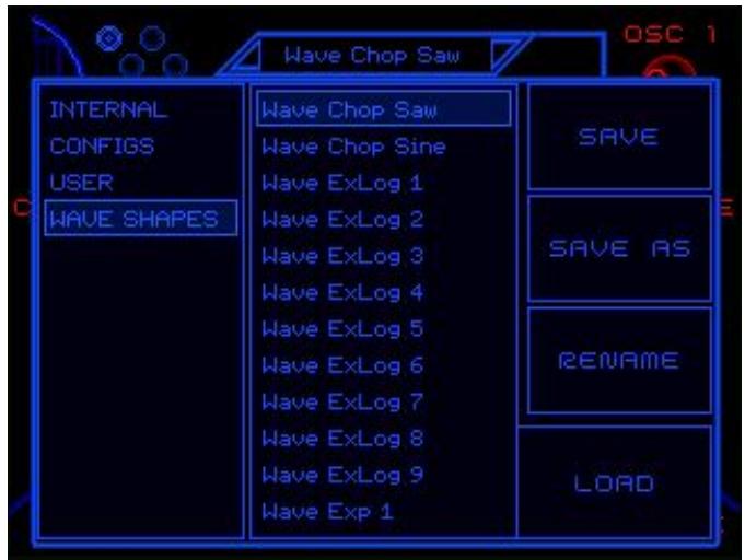
by using the left knob to scroll through Banks and the right knob to scroll through Presets, and then use the LOAD button to load the preset. Tap the top name field again to close the browser window.
The preset Browser also allows you to SAVE a currently edited Preset. Pressing the SAVE button stores the Preset in place, unless it comes from the Internal bank, which is a protected memory space. SAVE AS will allow you to store the preset in a different bank and change the name if desired. You can also select which bank you want to store into

by selecting the bank name in the upper left corner of the screen. Finally, RENAME allows you to change the name of a non-Internal bank Preset.
Virtual Knobs
The four Virtual Knobs correspond to the physical knobs on the front panel of the module. Each knob can be labeled to describe its macro function, and contains level indicators for knob position (outer ring) and incoming modulation (inner ring). Touching the onscreen knob graphic will reset it to its default position.
Grid Map
The Grid Map shows which Modulation CV Inputs are assigned to various controller paths around the user interface. Each of the 20 blocks in the grid corresponds to the 20 CV Input jacks on the front panel. Blocks within the grid are highlighted to indicate which jacks are paired with the controllers next to their Grid Map graphic. Grid Maps can be found in multiple places throughout the user interface, wherever it is useful to see Modulation CV Input assignments.
It's important to note that the Grid Map concept also applies to MIDI CCs and modulation Control Paths. Each square on the Grid Map represents the summation of a single Control (Knob or XY Pad), and its corresponding CV input jack, plus a MIDI CC assignment, all of which are also arranged on the same Grid reference. From there, the modulation Control Path signal is routed to destinations in the oscillator parameters. Having everything line up to the Grid Map greatly simplifies modulation routing in the Waverazor Dual Oscillator module.
Vertical and Horizontal Zoom
Appearing on either side of the waveform display are sets of Vertical and Horizontal
Zoom controls, indicated by vertical and horizontal lines respectively. Touching the waveform display ring above and below the center line changes the zoom setting. Touching above will zoom in, while below zooms out. As you zoom in and out, indicator lines will light up to show the current zoom setting.
Edited Flag
The word “Edited” will light up next to the Preset Browser if any storable edits are made to the Preset. These changes include knob and XY controller movements in addition to oscillator parameter values, but do not include changes to System settings, which are global to the unit and saved automatically.
Phase Reset Button
Pressing this button resets the phase of razor and all its wave segments for the oscillator that you are currently viewing. This is useful if you want to reset a wave sequence to its beginning step, or to reconstruct a waveform if its segments have been modulated out of their correct starting phases.
Clock Indicator
The Clock Indicator lights if it detects a clock signal patched into the Clock Input jack on the front panel. It also shows if clock sync is turned on for the current preset. The clock input can be used to advance the steps of a wave sequence.
Waveform Display
The waveform display allows you to visualize the wave shape either dynamically or statically, depending on the mode selected. It can also provide a view of the AUD / CV 2 Input signal for oscilloscope monitoring of an external source.
Scope Mode Indicator
Pressing the Scope Mode Indicator toggles through three settings for the waveform display. It defaults to oscilloscope mode (the third circle), monitoring the audio output for the currently selected oscillator. With the first circle selected, the waveform display monitors the high res CV (or audio) input for the currently selected oscillator, and if the middle circle is lit, a fixed waveform display is shown.
XY Pad Performance Screen
The XY Pad Performance Screen allows you to perform modulations with the swipe of your finger. The control works in two dimensions, X (horizontal) and Y (vertical), and there are two red dots indicating these tandem controllers' positions. Modulations of the X and Y positions are shown with smaller blue dots.

Editing Parameters
Pressing the INFO button brings you to the Main Edit Menu, your editing launchpad. From here, you can access all the parameters of the module from System settings to oscillator adjustments. The module remembers the last edit page you accessed during your session, so it's possible to press HOME to check the waveform or adjust the knobs, and then press INFO to return to wherever you left off in your editing. When you're in the editing pages, pressing the INFO button again will take you back to the main Edit Menu.

The Edit pages often offer additional pages that can be accessed by pressing the BACK and NEXT buttons. Below these buttons, the current page number is displayed. Parameter values are adjusted by turning their corresponding front panel knobs, and they can be reset to default value by tapping the onscreen parameter values with your finger.
SYSTEM Settings
The SYSTEM settings govern global aspects of the module and its behavior. Changes made to these parameter values are stored automatically to a preferences file on the microSD card. (If the card is removed, the module will not be able to access the preferences and it will use default values instead.) Note that in the center of the SYSTEM pages there is a small circular button, and pressing it will reset all SYSTEM settings to their default values.

Language - Sets the Language for the module. Try changing it to Klingon!
Brightness - Adjusts the brightness of the display.
Color A - Selects one of eight colors for the user interface, allowing you to customize your color scheme.
Color B - Selects one of eight colors for the user interface, allowing you to customize your color scheme.
XY Scope Bright - You can add the oscilloscope waveform to the XY performance page by turning up this parameter. It defaults to Off.
Clock In Smooth - If you are experiencing erroneous triggers from your clock input source, try using this setting to de-bounce the signal.
Log File - When turned on, the module generates a diagnostic log file that can be used to analyze performance. It's best to leave this off unless instructed by MOK to turn it on.
CV Settings
On the CV settings pages, you'll find parameters that govern how the two high resolution CV inputs and the 20 modulation (MOD) CV inputs behave when receiving control voltages. The first page is the CV/MOD SETTINGS menu, which allows you to monitor CV input levels using the meters on the left side of each button, and to jump directly to a specific CV input by touching the desired button. Each CV input has two parameters that shape the incoming signal.

Scale - Scales the incoming control voltage signal. It defaults to 100%, but can go from -200% to positive 200%.
DC - Sets a DC offset for the incoming control voltage signal.
MIDI Settings
On the MIDI settings pages, you'll find parameters affecting how MIDI is passed along to the oscillators. The Waverazor Dual Oscillator module responds to note data by changing pitch, but does not reset the oscillator as a full synthesizer instrument might do with its voice. Multiple Continuous Controllers (CCs) can also be assigned to modulation Control Paths here. They line up to the same modulation Grid Map as the Knobs and CV input Jacks.

Osc 1 Chan - Assigns a MIDI channel number to oscillator 1.
Osc 2 Chan - Assigns a MIDI channel number to oscillator 2.
Ctls Chan - Designates a MIDI channel number to carry Continuous Controllers.
Editor ID - Designates a MIDI channel number to carry Patch Changes and User Interface commands.
Ctl 1 CC - Ctl 20 CC - Assigns a Continuous Controller to the numbered modulation Control Path. A modulation Grid Map is provided on each page for reference.
Home Next CC - Assigns a Continuous Controller to advance the screen display to the next Home page in order, as if the Home button were pressed.
Home Prev CC - Assigns a Continuous Controller to change the screen display to the previous Home page in order (the opposite of pressing the Home button).
Patch Next CC - Assigns a Continuous Controller to advance the currently
loaded preset to the next preset in order, as if the browser increment button were pressed.
Patch Prev CC - Assigns a Continuous Controller to change the currently loaded preset to the previous preset in order, as if the browser decrement button were pressed.
ABOUT Page
The About page provides useful information about your Waverazor Dual Oscillator module. Here, you can find your current Firmware Version number, and your individual Serial Number, which you can use to register your hardware to your MOK user account. Registration gives you access to the latest Firmware updates and downloads. You can dismiss the About page by touching anywhere on the screen, returning you to the Main Edit Menu.

OSC CONFIG Settings
The Oscillator Configuration settings govern global parameters affecting oscillator behavior, such as CV routing, pitch scaling and output mixing. Special functionality like FM, external triggering, and audio input to the razor can be set up here.
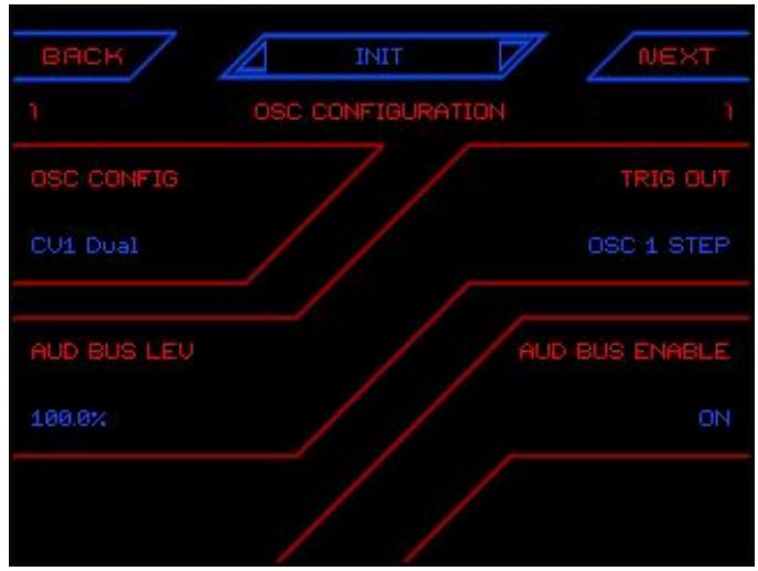
Osc Config - Determines how the module responds to the high res CV inputs.
CV1 Dual - CV1 is the pitch CV source for both oscillators.
CV1 Dual 2 - CV1 is the pitch CV source for both oscillators, however CV1 and CV2 each have their own CV scaling controls.
CV1 : CV2 - CV1 is routed to oscillator 1 and CV2 is routed to oscillator 2. They are routed independently and have separate scaling controls.
CV1:2 Mux - CV1 and CV2 have separate scaling controls, but the results are multiplied together for each CV path. This setup is useful for some exotic types of FM synthesis.
CV1:2 Sum - CV1 and CV2 have separate scaling controls, but the results are summed together for each CV path. This setup is useful for classic FM synthesis with the modulator's CV Type set to Zero-Lin (through zero, linear).
Trig Out - Governs what triggers are sent out through the Trigger Output jack.
Off - No triggers are sent.
Osc 1 Cycle - A trigger is sent each time oscillator 1 completes one reference cycle.
Osc 1 Step - A trigger is sent each time oscillator 1's razor advances one step.
Osc 2 Cycle - A trigger is sent each time oscillator 2 completes one reference cycle.
Osc 2 Step - A trigger is sent each time oscillator 2's razor advances one step.
Aud Bus Lev - Here's where you set the level for the external audio input coming through the AUD / CV2 Input jack. It defaults to 100% , but can boost up to 400% . Negative amounts invert the phase of the signal.
Aud Bus Enable - Switches the audio input bus on and off.
CV 1 Type - Determines the behavior of the CV 1 input.
V/Oct - Exp - Sets Volt per Octave CV response. Zero volts references the root pitch of the oscillator (default C3, 261.63 Hz). Positive voltage moves pitch upward while negative voltages move the pitch downward.
Hz/V - Lin - Sets Hertz/Volt CV response. Zero volts references the root pitch of the oscillator (default C3, 261.63 Hz). Positive voltage moves pitch upward while negative voltages move the pitch downward.
Unity-Exp - Sets exponential CV response. Zero volts references the root pitch of the oscillator (default C3, 261.63 Hz). Positive voltage moves pitch upward while negative voltages inversely move the pitch upward in reference to root.
Unity-Lin - Sets linear CV response. Zero volts references the root pitch of the oscillator (default C3, 261.63 Hz). Positive voltage moves pitch upward while negative voltages inversely move the pitch upward in reference to root.
Zero-Exp - Provides exponential CV tracking, starting from 0 Hz. Positive voltage moves pitch upward while negative voltages inversely
move the pitch upward from zero. Used primarily for FM, summing in signal from a modulation oscillator with the other CV source governing pitch. A typical FM setup might have V/Oct - Exp for CV 1 and Zero-Exp for CV 2, with the modulation plugged into the CV 2 jack.
Zero-Lin - Provides linear CV tracking, starting from 0 Hz. Positive voltage moves pitch upward while negative voltages inversely move the pitch upward from zero. Used primarily for FM, summing in signal from a modulation oscillator with the other CV source governing pitch. A typical FM setup might have V/Oct - Exp for CV 1 and Zero-Lin for CV 2, with the modulation plugged into the CV 2 jack.
CV Osc 1 - Turns the CV input response on or off for oscillator 1.
CV 1 Scale - Scales the oscillator 1 CV response. It defaults to 100%, but can boost up to 200%, or invert tracking to -200%.
CV 1 DC - Sets a DC offset amount for the CV signal routed to oscillator 1.
CV 2 Type - Determines the behavior of the CV 2 input. (See description of CV 1 Type above for details.)
CV Osc 2 - Turns the CV input response on or off for oscillator 2.
CV 2 Scale - Scales the oscillator 2 CV response. It defaults to 100%, but can boost up to 200%, or invert tracking to -200%.
CV 2 DC - Sets a DC offset amount for the CV signal routed to oscillator 2.
Osc 1 Out Level - Sets the output level for oscillator 1. Negative values invert the signal phase.
Osc 2 Out Level - Sets the output level for oscillator 2. Negative values invert the signal phase.
Osc 1 Mix Level - Sets the amount of oscillator 1 to be sent to the Mix Output. Negative values invert the signal phase.
Osc 2 Mix Level - Sets the amount of oscillator 2 to be sent to the Mix Output. Negative values invert the signal phase.
OSC 1 and OSC 2 Settings
The OSC1 and OSC 2 settings pages contain all the parameters that shape the timbre and behavior of oscillators 1 and 2 respectively. Each wave slicing oscillator consists of a razor (the wave slicer), up to 8 wave segments, and a master section that ties it all together. When you first select an oscillator for editing, you'll see the Oscillator Sub Menu. Active wave segments are highlighted with blue text (or whichever color is selected for Color B in the System settings.)

Oscillator Master Settings
The Master settings affect the sound and behavior of the entire oscillator. When you press the Master button in the Oscillator Sub Menu, it takes you to the first of two Master pages. To return to the Oscillator Sub Menu, press the OSC button at the bottom of the page.

Level - Sets the volume level of the oscillator. Negative values invert polarity.
Polarity - A switch that flips polarity immediately between positive and negative.
Ext Clock - Turns external clock sync on or off for the oscillator. Turning it on synchronizes the razor steps to the clock pulses received on the Clock Input jack.
Ext Clock Div - Acts as a clock divider on the external clock input.
CV Scale - Turns CV tracking for the oscillator on or off.
Wave Track - Turns wave pitch tracking for all segments on or off.
Wave CV - Turns wave CV tracking for all segments on or off.
Wave Sync - Sets the hard sync mode for all wave segments. The choices are:
none - The wave segments are free-running.
cycle - Resets the wave segment when a Razor cycle is completed. Completion of the Razor cycle is dependent on the number of steps, in relation to step size, and is defined as when the waveform sequence repeats itself.
wave - The segment will reset on every wave period. This will keep the segment in the same phase position with each wave period even when the cycle length is greater than 1, as in the case of odd step and size combinations.
step - The segment will reset on every segment step. The wave will begin from its start phase, in every step in which it appears.
Key Track - Turns key tracking for the oscillator on or off. With Key Track off, the oscillator does not respond to any pitch control.
Key Track % - Scales key tracking for the oscillator. It defaults to 100%, but can over track up to 200%, or invert tracking to -200%.
Oscillator Razor Settings
The Razor is the unique component of the oscillator that slices and sequences the individual wave segments into a full waveform. When you press the Razor button in the Oscillator Sub Menu, it takes you to the first of two Razor pages. To return to the Oscillator Sub Menu, press the OSC button at the bottom of the page.

Num Steps - Defines the number of waveform slices available for creating the composite waveform output.
Step Size - Changes the segment size, from fractions of a cycle to multiples of a cycle.
Step Frac - Fractionally increases or decreases the Step Size. Under most circumstances, adjusting this parameter will make the overall wave cycle fractionally unaligned, creating inharmonic frequencies.
Step Fine - Provides fine tuning of the Step Frac parameter. This only has an effect when Step Frac is set to something other than 100%.
Tune Oct - This is a quantized octave tuning adjustment. It is useful for when you want to adjust or modulate only the octave setting of the Razor.
Tune Semi - This is a quantized semitone tuning adjustment with a range of +/- 1 octave. It is useful for when you want to adjust or modulate only the semitone (note) setting of the Razor.
Tune Cents - This provides a small range (+/- 1 semitone) in cents for fine
tuning adjustment. It is useful for making small changes to the Razor tuning.
Window Duty - Allows adjustment of duty cycle of alternating steps of the Razor segments.
Oscillator Wave Settings
You can independently adjust the settings for the individual wave segments that comprise the full output waveform. When you press any of the Wave buttons in the Oscillator Sub Menu, it will take you to its corresponding Wave edit pages. To return to the Oscillator Sub Menu, press the OSC button at the bottom of the page.

Shape - Selects which of the 127 available wave shape to use in the segment. Can also be set to Off.
Level - Sets the output level for the wave segment, from -100% to 100%. Negative values will invert the polarity of the waveform, e.g. -100% is the same level as 100%, but with inverted polarity.
Phase - Sets the starting phase of the wave segment. You can choose a setting from 0 to 360 degrees in relation to the full waveform cycle. With a free running oscillator, the Phase will be an offset from the current reference cycle phase. Each of the Wave segments and even the Razor can have different phase relationships to the reference cycle.
DC - Adjusts the amount of DC offset (bias) applied to the wave segment. The DC offset amount is bipolar, so negative or positive bias can be applied.
Tune Oct - This is a quantized octave tuning adjustment. It is useful for when you want to adjust or modulate only the octave setting of the wave segment.
Tune Semi - This is a quantized semitone tuning adjustment with a range of +/-12 steps. It is useful for when you want to adjust or modulate only the semitone (note) setting of the wave segment.
Tune Cents - This setting has a small range (+/- 1 semitone) in cents for fine tuning adjustment. It is useful for when you are creating small changes to the wave segment tuning.
Const Pol - With Const Pol set to On, the wave segment keeps its wave energy in the polarity that it's meant to be in, according to its relationship to the reference phase. If the wave energy crosses over the zero boundary it is wrapped back into the correct polarity.
Key Track - Selects whether Key Track for the segment follows the Main Oscillator, its own key track parameter (self), or turns it off.
Key Track % - Adjusts the Key Tracking of the wave segment, relative to its pitch. 100% is the default value, meaning that the pitch will move one octave with each octave on the keyboard (or equivalent CV input). Smaller values will result in smaller pitch changes for each keyboard note movement, and larger values result in larger changes. To reverse the pitch to keyboard relationship, you can set Key Track to negative values. Key Tracking is centered around C3.
CONTROL Path Settings
The Control Paths are super modulation routes that collect signals from multiple sources and connect them to oscillator parameter targets. A single Control Path sums signals from its Control (a knob or XY pad dimension), and its corresponding modulation inputs (CV input jacks and MIDI CC assignments). Pressing any of the buttons in the Control Settings Sub Menu will take you to its
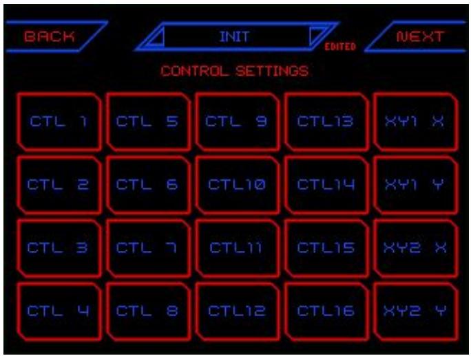
corresponding Control edit page where you can shape the modulation signal and how it affects its various target parameters.
There are 20 modulation Control Paths, which can route to multiple destinations. To keep track of all the assignments, it helps to reference the Grid Map graphic which appears on every Control edit page. (Each Control Path corresponds to a single square on the Grid Map.) It may also be useful to press INFO and jump to the CV / MOD SETTINGS page, where you can see live metering of CV input signals. Those 20 CV buttons correspond to the 20 Control buttons, which also line up to Grid Map. Or you can press HOME to check a particular knob or XY pad Control assignment and reference their nearby Grid Map. To return to the Control Settings Sub Menu, press the CONTROLS button at the bottom of the edit page.
Ctl Value - This is the value of the Control (Knob or XY Pad dimension) that appears on the main performance pages. It allows you to test the control's behavior while editing, and can be set and stored with the Preset.
Def Value - Sets the default value for the Control. The default value is the setting used when you tap on the corresponding virtual knob in the main performance page.
CV Scale - Scales the CV response to the Control Path. It defaults to 100%, but can boost up to 200%, or invert tracking to -200%.
CV DC - Sets a DC offset amount for the CV signal routed to the Control Path.
Name - Allows you to name the Control. The Control names will label their corresponding knobs on the main performance pages. This works for all Controls except the XY pad dimensions, which cannot be named.
(Path View) - Use the corresponding knob to select the modulation destination path from the onscreen list for editing. Note that some Control Paths have only one destination.
Source - Sets the amount to scale the source signal. This is a bipolar parameter, so negative values will invert the modulation polarity.
Mod Level - Sets the level of signal output to the destination. This is a bipolar parameter, so negative values will invert the modulation polarity.
Mod DC - The amount of DC offset (bias) applied to the signal after Level adjustment. Using this parameter allows for sliding the output value up or down, which is useful for positioning a modulation signal into a particular range of the destination parameter. The DC offset amount is bipolar, so positive or negative bias can be applied.
Appendix A - Wave Shapes
| None | ExLog 3 | LogSawUp 1 |
| Sine | ExLog 4 | LogSawUp 2 |
| Sinelnv | ExLog 5 | LogSawUp 3 |
| SineEx | ExLog 6 | LogSawUp 4 |
| SineLog | ExLog 7 | LogSawUp 5 |
| Triangle | ExLog 8 | LogSawUp 6 |
| Exp 1 | ExLog 9 | LogSawUp 7 |
| Exp 2 | LogEx 1 | LogSawUp 8 |
| Exp 3 | LogEx 2 | LogSawUp 9 |
| Exp 4 | LogEx 3 | Saw Down |
| Exp 5 | LogEx 4 | ExpSawDn 1 |
| Exp 6 | LogEx 5 | ExpSawDn 2 |
| Exp 7 | LogEx 6 | ExpSawDn 3 |
| Exp 8 | LogEx 7 | ExpSawDn 4 |
| Exp 9 | LogEx 8 | ExpSawDn 5 |
| Log 1 | LogEx 9 | ExpSawDn 6 |
| Log 2 | Saw Up | ExpSawDn 7 |
| Log 3 | ExpSawUp 1 | ExpSawDn 8 |
| Log 4 | ExpSawUp 2 | ExpSawDn 9 |
| Log 5 | ExpSawUp 3 | LogSawDn 1 |
| Log 6 | ExpSawUp 4 | LogSawDn 2 |
| Log 7 | ExpSawUp 5 | LogSawDn 3 |
| Log 8 | ExpSawUp 6 | LogSawDn 4 |
| Log 9 | ExpSawUp 7 | LogSawDn 5 |
| ExLog 1 | ExpSawUp 8 | LogSawDn 6 |
| ExLog 2 | ExpSawUp 9 | LogSawDn 7 |
33
© 2019 Media Overkill
www.mok.com
| LogSawDn 8 | Rand S8 | Noise S6 |
| LogSawDn 9 | Rand S9 | Noise S7 |
| RipSawUp | Rand R0 | Noise S8 |
| RipSawDown | Rand R1 | Noise S9 |
| Chop Saw | Rand R2 | Noise R0 |
| Chop Sin | Rand R3 | Noise R1 |
| SawTri Up | Rand R4 | Noise R2 |
| SawTri Dn | Rand R5 | Noise R3 |
| Square | Rand R6 | Noise R4 |
| Pulse | Rand R7 | Noise R5 |
| Rand S0 | Rand R8 | Noise R6 |
| Rand S1 | Rand R9 | Noise R7 |
| Rand S2 | Noise S0 | Noise R8 |
| Rand S3 | Noise S1 | Noise R9 |
| Rand S4 | Noise S2 | AudIn |
| Rand S5 | Noise S3 | |
| Rand S6 | Noise S4 | |
| Rand S7 | Noise S5 |
Appendix B - Preset Bank and Control Notes
The Preset Banks are divided into four groups. INTERNAL lives in an onboard memory space and is intended to provide a demonstration of a few types of presets, even when the microSD card is not available. All of these presets are duplicates of sounds found in other banks except for the Oscilloscope preset, which allows you to monitor waveforms plugged into the AUD / CV 2 Input.
The CONFIG 1 and 2 banks contain a full selection of oscillator configurations. Waverazor Dual Oscillator Presets are not like full synth presets, in that they are not fully playable sounds with envelopes and LFOs, but instead are oscillator setups designed to perform particular functions within a modular voice.
Although you can save Presets anywhere except for the Internal bank, the USER bank is where people are intended to save their own patches. Anyone can change and delete the folders on their cards, but the module will always rebuild a USER bank if it can't find one.
The WAVE SHAPES bank contains presets that are all based on the same type of general purpose configuration, but have the wave shapes swapped out so that each of the 127 shapes is represented. Although many presets have a shape control that scrolls through all of the waves, that knob can sometimes be hard to manipulate precisely, and additionally, there's no easy way to see the name of the shape that has been selected. The WAVE SHAPES bank helps you get directly to your desired waveform setting.
What types of Presets are in the CONFIGS banks?
Alter Wave 2s - This preset type is meant to allow different wave shape selections in alternating wave slices. There are knobs for EVEN and ODD wave slice shape selection. The "2s" at the end of this particular name stands for "2 Segments", and there are 2 through 8 segments represented across this overall series (2s through 8s). It should be noted that the number of segments affects the harmonics generated, through the frequency relationship between the Razor and the waves being sliced.
The Audio Input presets route external audio from the AUD / CV 2 input through the oscillators for slicing. The preset Audio Input 1 brings audio through 1/4 of the waveform, while Audio Input 2 does 1/2 of the wave. Audio In Chop routes audio
through all 4 slices, with individual volume control for each slice in order to generate discontinuities.
Combo Wave - Similar to Alter Wave, but all slices have different starting wave shapes already selected.
Cycle 2-1 - In the Cycle series, the first number is the number of steps in the Razor. The second number is wave cycles per step. The Cycle presets explore how the fractional math in the razor affects harmonic generation.
FM - There are several FM presets providing different types of frequency modulation, from exponential (analog style) to linear (DX style), and with different offsets. When configured for FM synthesis, both oscillators respond to CV pitch from the CV 1 Input, while the FM modulation is patched in via the AUD / CV 2 jack.
INIT - A template preset in default state.
Multi-Sync Cyc2s - These presets have Multi-Sync always engaged. The "Cyc" variant resets all waves according to the Razor wave cycle. The "Stp" variant resets waves according to their individual step or segment. The "Wav" variant resets waves according to their own wave period, which maintains phase even if the Razor and its steps are doing something crazy in relation to the waves being sliced.
Mutant AM - These presets are set up with individual pitch control for each wave segment, so that a wide range of AM frequency relationships can be set. Mutant AM is the combination of all the amplitude modulation happening across all the wave slices in the oscillator.
Phase - These presets are set up to be able to shift the phases of each segment out of alignment, creating discontinuities for harmonic generation.
Swarm Saw Dn - Swarm presets are intended for the oscillators to be stacked (although they don't have to be) and monitored from the MIX output. The 8 segments of each oscillator are detuned progressively farther apart in order to create a super-saw type of effect, but with your choice of wave shape. The CV 1 input is routed to both oscillators in this configuration for synchronous pitch control.
WaveSeq01 Manual - These presets intend for the Razor to slice at BPM rate, creating a rhythmic wave sequence. The "Manual" variant provides control of the razor frequency via knob, while the "Clock" variant advances the razor steps according to the clock input.
Independent Clock Division settings are found in the "Master" sections for each oscillator.
What do the Controls do? (Knob Assignments)
Coarse, Fine, Octave and Semitn - These are familiar controls for oscillator pitch. Octave and Semitone are quantized, and summed, with the other pitch controls.
Shape - Scrolls through wave shape settings.
R-Size - Multiplies or Divides the step size of the razor.
R-Duty - Changes the Duty Cycle of the razor.
Cnspol - Short for Constant Polarity. When turned on, the wave energy for each segment remains in the correct wave polarity according to the razor cycle. Without this, the wave segments can end up in DC offset, depending on how their cycles line up. On the rare occasion that this might happen, our automatic DC rejection is engaged, but the end result is that the wave becomes quieter as it's re-centered. Constant Polarity avoids this condition, but can also introduce a square wave quality to the sound.
X-Vol - Modulates the volume of all wave segments by different amounts simultaneously.
Vol 1-4 - Volume control for individual segments. Bipolar volume controls will flip phase as they go through zero.
M-Sync - A 4 position Multi-Sync setting affecting all wave segments. Rotating clockwise, the values are Off, Cycle, Wave, and Step.
X-Tune - Modulates the pitch of all wave segments by different amounts simultaneously.
Odd Wv, Evn Wv - Changes the wave shapes of all odd, or even wave segments respectively.
Tune 1-3 - Tuning control for individual wave segments.
X-Phas - Modulates the phase of all wave segments by different amounts simultaneously.
R-Frac - Un-quantized coarse adjustment of the razor frequency.
R-Fine - Fine tune adjustment of the razor frequency.
1-2 Vol - Changes the overall volume of oscillator 1 or oscillator 2 respectively.
1-2Shape - Changes the overall wave shape of oscillator 1 or oscillator 2 respectively.
Appendix C - Audio Block Diagram

Waverazor Community
For additional information, please join the conversation at the MOK User Forum: https://shrine.mok.com/
To keep up with the latest MOK news, please join our no-spam mailing list at: http://mok.com/
Or like us on Facebook, follow us on Twitter, and subscribe to us on YouTube. We are here for you!
- Rob, Taiho and Chris
US Patent
US10262646B2
Robert Rampley, Taiho Yamada
Media Overkill LLC
Media Overkill, MOK and Waverazor are trademarks of Media Overkill, LLC.
Specifications subject to change without notice.
- WAVERAZOR DUAL OSCILLATOR MANUAL V
- FOREWORD
- ABOUT WAVE SLICING SYNTHESIS
- FRONT PANEL CONTROLS AND I/O
- MULTI-TOUCH SCREEN DISPLAY ELEMENTS AND CONTROLS
- EDITING PARAMETERS
- APPENDIX A - WAVE SHAPES
- APPENDIX B - PRESET BANK AND CONTROL NOTES
- APPENDIX C - AUDIO BLOCK DIAGRAM
- WAVERAZOR COMMUNITY
- PERSISTENCE MIXING
- WAVEFORM DISCONTINUITIES
- RAZOR WINDOW DUTY
- FRACTIONAL HARMONICS AND RHYTHMS
- MUTANT AM
- MULTI-SYNC
- SPIRIT OF EXPLORATION
- HOME BUTTON
- INFO BUTTON
- KNOBS
- MULTI-TOUCH SCREEN
- MICROSD CARD SLOT
- MIDI INPUT
- CLOCK INPUT
- CV 1 INPUT
- AUD / CV 2 INPUT
- MODULATION CV INPUTS
- AUDIO 1 AND AUDIO 2 OUTPUTS
- MIX OUTPUT
- TRIGGER OUTPUT
- PAGE INDICATOR
- INPUT METERS
- PRESET BROWSER
- VIRTUAL KNOBS
- GRID MAP
- VERTICAL AND HORIZONTAL ZOOM
- EDITED FLAG
- PHASE RESET BUTTON
- CLOCK INDICATOR
- WAVEFORM DISPLAY
- SCOPE MODE INDICATOR
- XY PAD PERFORMANCE SCREEN
- SYSTEM SETTINGS
- CV SETTINGS
- MIDI SETTINGS
- ABOUT PAGE
- OSC CONFIG SETTINGS
- OSC 1 AND OSC 2 SETTINGS
- OSCILLATOR MASTER SETTINGS
- OSCILLATOR RAZOR SETTINGS
- OSCILLATOR WAVE SETTINGS
- CONTROL PATH SETTINGS
- WHAT TYPES OF PRESETS ARE IN THE CONFIGS BANKS
- WHAT DO THE CONTROLS DO? (KNOB ASSIGNMENTS)
Brand : 1010music
Model : Waverazor Dual Oscillator
Category : Electronic musical instrument