
RD770 Monstermat - Professional audio equipment EVENTIDE - Free user manual and instructions
Find the device manual for free RD770 Monstermat EVENTIDE in PDF.
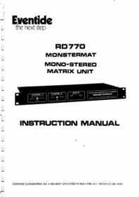


| Product type | Professional mono/stereo audio matrix |
| Brand | Eventide |
| Model | RD770 |
| Main functions | Mono-stereo conversion, noise reduction, routing matrix |
| Channels | 3 channels (Channel 1, 2, 3) |
| Inputs | Balanced audio line inputs |
| Outputs | Balanced audio line outputs |
| Noise reduction | Activatable per channel with automatic mode (AUTO) |
| Operating mode | Switchable mono/stereo |
| Source switching | REPRO/RECORD selector for each channel |
| Status indicator | STATUS LED on the front panel |
| Power supply | Mains 100-240 V AC, 50/60 Hz |
| Dimensions | 19-inch rack format, 1U height (estimated) |
| Weight | Approximately 3 kg |
| Chassis | Robust metal case |
| Maintenance | Exterior cleaning with a soft, dry cloth |
| Cleaning | Do not use solvents or abrasive products |
| Safety | Do not open the device; no user-serviceable parts |
| Spare parts | Available from Eventide after-sales service |
| Repairability | Repair by an authorized Eventide technician |
| Warranty | 1 year against defects in materials and workmanship |
| Country of origin | United States |
Frequently Asked Questions - RD770 Monstermat EVENTIDE
User questions about RD770 Monstermat EVENTIDE
0 question about this device. Answer the ones you know or ask your own.
Ask a new question about this device
Download the instructions for your Professional audio equipment in PDF format for free! Find your manual RD770 Monstermat - EVENTIDE and take your electronic device back in hand. On this page are published all the documents necessary for the use of your device. RD770 Monstermat by EVENTIDE.
USER MANUAL RD770 Monstermat EVENTIDE
Eventide
the next step
RD770
MONSTERMAT
MONO-STEREO
MATRIX UNIT

INSTRUCTION MANUAL
LIMITED WARRANTY
ALL EVENTIDE EQUIPMENT IS WARRANTED FOR A PERIOD OF ONE YEAR
from the date of purchase from Eventide or an authorised dealer, against defects in material or workmanship. In case of difficulty, consult Eventide or your dealer for instructions.
This warranty does not apply to mechanical defects caused by use or rough handling, or to damage caused by improper operation not in accordance with this manual. Cause of defect is in the sole judgement of Eventide. There are no other express or implied warranties, and no warranty of merchantability or fitness for a particular purpose.
The warranty is voidable at Eventide's option under the following circumstances:
- if the equipment is connected to an improper voltage supply.
- if the user makes unauthorized modifications of any type. If such modifications are made, user agrees to pay for any time or parts necessary to remove the modification before repair.
Eventide will under no circumstances be responsible for consequential damages caused by failure of equipments of its manufacture, or for any other reason. Our sole liability is for repair or replacement of defective parts, under the terms of the warranty.
SHIPPING
Equipment should be returned, if possible, in the original packing container. Loose cards must be wrapped in conductive foil (damage caused by failure to do this will render the warranty void). If the original container is not available, the equipment must be packed to prevent damage from crushing or dropping. Damage caused by inadequate packing for service return is not covered by warranty. We recommend shipping via UPS rather than by US mail, and air freight if you are in a hurry. If in our opinion the packing container is inadequate for return shipment, we reserve the right to supply a new container and charge for same.
The warranty covers return shipping in the continental US except Alaska. Return shipments will not be insured unless the customer requests and agrees to pay for same. If a more expensive form of shipment is requested, customer will be charged for same.
ALL RETURNED UNITS, IN OR OUT OF WARRANTY, MUST BE PREPAID TO OUR DOOR.
ALL RETURNED UNITS MUST BE ACCOMPANIED BY A COMPLETE TROUBLE REPORT, DETAILING ALL THE PROBLEMS EXPERIENCED, CONDITIONS OF OPERATION, ETC.
FOREIGN SHIPMENTS
Foreign shipments must be returned fully prepaid, including Customs and brokerage charges. Repaired equipment will be shipped all charges collect. A commercial invoice stating 'goods of US manufacture - being returned for repair' and giving a fair market value of the unit should accompany the shipment, to save time and expense. A copy of this invoice should also be mailed to Eventide.
REPLACEMENT OF PARTS UNDER WARRANTY will be done free of charge provided that the defective parts and the warranty card for the unit are received by Eventide.
EVENTIDE CLOCKWORKS INC.
WARRANTY REGISTRATION FORM MODEL RD770 MONSTERMAT
DATE PURCHASED____ SERIAL NUMBER____
FROM WHOM PURCHASED
NAME OF PURCHASER
ADDRESS
TELEPHONE NUMBER
From time to time, application notes and other data may be made available. To whom should this information be sent?
NAME ____
ADDRESS
OPTIONAL - PLEASE FILL OUT IF YOU HAVE TIME
HOW DID YOU LEARN OF EVENTIDE EQUIPMENT?____
If you would like to receive literature on other Eventide products, please check as indicated below:
BD955 BROADCAST DELAY LINE ( ) 1745M AUDIO DELAY LINE ( )
H949 HARMONIZER ( ) H910 HARMONIZER ( ) 2830 OMNIPRESSOR ( )
FL201 INSTANT FLANGER ( ) THS224 REAL-TIME ANALYZER ( )
* * * * *
IMPORTANT: YOU MUST FILL OUT THIS FORM TO ENSURE WARRANTY PROTECTION
AND MAIL WITHIN TEN DAYS OF PURCHASE TO:
EVENTIDE CLOCKWORKS INC., 265 WEST 54TH STREET, NEW YORK NY 10019
CONNECTION INSTRUCTIONS
The MONSTERMAT has two channels, each channel being configured for stereo operation, either reproduce (expand, play), or record (compress).
CHANNEL 1 is ALWAYS reproduce
CHANNEL 2 may be either reproduce or record, depending on internal settings. The function may be identified by the serial number plate and/or the front panel CHANNEL 2 STATUS light.
For a double reproduce unit, connection of channel 2 is identical to that of channel 1, so channel 1 connection only will be described.
ALIGNMENT Units are factory aligned so that equivalence between compressed/ expanded and non-processed signals occurs at +4 dBm. This means that with a. +4 dBm, 1 kHz input, the output level from each channel will be identical in the dbx IN and dbx OUT modes. For alignment to different levels, refer to the alignment section of the manual.
NOTE that the dbx noise reduction system is not critically level dependent, and precise alignment to absolute level is not required, as it is with the Dolby system.
The rear of the chassis is screened as to INPUT, OUTPUT, and SIGNAL POLARITY. LEFT and RIGHT signals should be connected as follows:
REPRODUCE LEFT + RIGHT (or MONAURAL) should be connected to terminals 1, 2, 3. LEFT - RIGHT should be connected to terminals 4, 5, 6. LEFT OUTPUT should be connected from terminals 7, 8, 9. RIGHT OUTPUT should be connected from terminals 10, 11, 12.
RECORD LEFT (or MONAURAL) should be connected to terminals 1, 2, 3. RIGHT should be connected to terminals 4, 5, 6. LEFT + RIGHT (or MONO INPUT TO CART) should be connected from terminals 7, 8, 9. LEFT - RIGHT (or RIGHT INPUT TO CART) should be connected from terminals 10, 11, 12.
IMPEDANCES Unless otherwise specified, all INPUTS are 20 k bridging, and all OUTPUTS are 600 ohms. Provision is made for adding an internal termination resistor, should this be desired. The output impedance may be reduced to 150 ohms by changing or paralleling internal resistors.
All inputs and outputs are electronically balanced. If the input signal is unbalanced, it should be connected to the + terminal, and the - terminal can either be grounded or left floating. If the device being fed requires an unbalanced input, it should be provided by the + terminal on the MONSTERMAT. If the - output is not to be used, it should be left floating.

REAR PANEL CONNECTIONS


CONNECTION OF CHANNEL 1
(RECORD/REPRODUCE UNITS)
CONNECTION OF CHANNELS 1 AND 2 (REPRODUCE/REPRODUCE UNITS)
FRONT PANEL CONTROLS AND INDICATORS
Channel 1 and Channel 2 - dbx noise reduction IN, OUT, and AUTO
CHANNEL 1/2
dbx NOISE REDUCTION

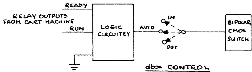
The dbx noise reduction circuitry can be switched in and out either by means of the front panel switch, or, if the unit is in AUTO, by means of control signals (see the section on control signals for details).
STATUS Channel 2
STATUS
CHANNEL 2
REPRO RECORD

As described in the Connection Instructions and elsewhere, Channel 1 is always reproduce, Channel 2 can be either record or reproduce, depending on factory-installed internal adjustments. The LED indicates the configuration of the particular unit.

REPRODUCE

RECORD
Notes: The reference to +4 dBm assumes that this is the normal alignment level at your facility. The purpose of performing alignment at a specific level is to ensure that the signal levels with dbx noise reduction IN conform to those with dbx noise reduction OUT. If you customarily align your equipment at 0 dBm or +8 dBm, substitute these numbers for +4 dBm in the instructions below.
When adjusting the matrix controls for null, it is convenient to use a high level signal, such as +4, for adjustment. However, any signal level which enables one to observe the output is usable, as the null is not level sensitive.
The frequency referred to, 1 kHz, is not sacred, and you may use 400 Hz or any nominal input frequency in the general area. It is, however, important to standardize on an alignment frequency, because the dbx cards are both frequency and level sensitive, and alignment at different frequencies will produce somewhat different results.
As supplied from the factory, the standard MONSTERMAT has a true 600 ohm output and a 20 k bridging input. They may be (or may have been) modified either to provide a 600 ohm terminated input, or a low impedance output, or both. In the case of the input modification, it may be necessary to readjust the output level of your signal generator as you switch the signal to the L - R (or R) input of the MONSTERMAT. The output modification, if present, will not affect the alignment procedure, since only unloaded voltage measurements are being made.
RECORD ALIGNMENT (Matrix Section)
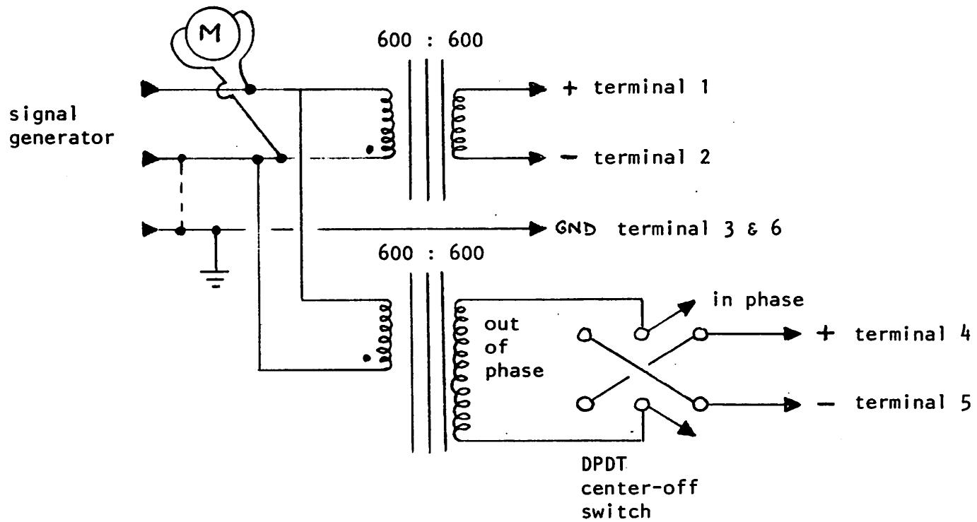
- Connect the test jig to the MONSTERMAT input as shown in Fig. 1. Apply a 1 kHz, +4 dBm signal to the jig. The dbx noise reduction switch should be OUT.
- Set the jig switch to center (OFF). Confirm that the output voltage (measured across + and -) is identical to the input voltage.
- Set the jig switch to IN PHASE. Confirm that the LEFT IN terminals now have double the input voltage, and that the RIGHT IN terminals now have little or no signal.
- Adjust the RIGHT NULL potentiometer (R3 on the parts location drawing) for minimum signal at the RIGHT IN terminals.
- Set the jig switch to OUT OF PHASE. Confirm that the RIGHT IN terminals now have double the input voltage, and that the LEFT IN terminals now have little or no signal.
- Adjust the LEFT NULL potentiometer (R4 on the parts location drawing) for minimum signal at the LEFT IN terminals.
- Set the jig switch to center (OFF).
RECORD ALIGNMENT (dbx cards)
- Measure the output voltage at the RIGHT IN terminals of the rear panel, while switching between dbx IN and OUT. Adjust the rear dbx card #3 REC LEVEL control until the output level remains constant while switching. This is an approximate adjustment which will be repeated after the distortion alignment.
- Set the jig switch to OUT OF PHASE. Adjust the front dbx card #4 REC LEVEL control until the output level remains constant while switching. Again, this is an approximate adjustment.
- Connect a jumper from pin 16 to pin 18 on dbx card #4.
- Turn the jig switch to center again, and connect a distortion test set or (preferably) a selective voltmeter or spectrum analyzer to the RIGHT IN terminals. Adjust the rear dbx card #3 VCA SYM control for minimum distortion.
- Set the signal generator frequency to 80 Hz. Adjust the rear dbx card #3 RMS SYM control for minimum distortion. It may be necessary to increase the input signal level if distortion cannot be nulled, and to reduce it again after the adjustment has been made.
- As the results of steps 11 and 12 are interactive, repeat them for minimum distortion. Then repeat steps 8 and 9 to compensate for level changes during distortion adjustment.
- Remove jumper from dbx card #4 (see step 10).
- Set the jig switch to OUT OF PHASE. Repeat steps 11, 12 and 13 for the front dbx card #4.
- Set the jig switch to IN PHASE. With the dbx switch IN, adjust the front dbx card REC LEVEL control for an output null at the RIGHT IN output (Monstermat terminals #10 and 11). This ensures that the dbx card levels are precisely set.
REPRODUCE ALIGNMENT (Matrix Section)
- Connect the test jig to the MONSTERMAT input as shown in Fig. 1. Apply a 1 kHz, +4 dBm signal to the jig. The dbx noise-reduction switch should be OUT.
- Set the jig switch to center (OFF). Confirm that the output voltage (measured across + and -) is TWICE the input voltage.
- Set the jig switch to IN PHASE. Adjust the RIGHT NULL pot (R1 on the parts location diagram) for minimum signal at the RIGHT OUT terminals #10 & 11.
- Set the jig switch to OUT OF PHASE. Adjust the LEFT NULL pot (R2 on the parts location diagram) for minimum signal at the LEFT OUT terminals #7 & 8.
REPRODUCE ALIGNMENT (dbx cards)
- Set the jig switch to center (OFF). The rear dbx card is associated with the RIGHT OUT terminals, the front dbx card is associated with the LEFT OUT terminals. Switching between dbx IN and OUT, adjust both dbx PLAY LEVEL controls so that the output levels remain constant. This is an approximate adjustment.
- Leaving the jig switch OFF, successively connect the distortion meter as in step 11 above to the two outputs, and adjust the dbx card VCA SYM controls for minimum distortion.
- Set the signal generator to 80 Hz, and successively adjust the dbx card RMS SYM controls for minimum distortion.
- Repeat steps 6 and 7 until no further adjustment is necessary. Then repeat step 5.
This completes the alignment of the MONSTERMAT analog section. It will only be necessary to repeat this alignment procedure if a dbx card is changed.
NOTE: There are no controls or adjustments for the power supply and control sections.
The two red LED's in the power supply section indicate that the power supplies are active, as they are special voltage-sensing devices, and will extinguish should power fall much below 15 V. They are not capable of detecting AC ripple, so if hum is present or suspected, an oscilloscope should be used to check.
TO MONSTERMAT
TERMINALS AS
INDICATED
CHANNEL ONE
CARTRIDGE REPRODUCE
CHANNEL TWO
if unit is RECORD/PLAY
SIGNAL SOURCE
if unit is PLAY/PLAY
CARTRIDGE REPRODUCE
ALIGNMENT TEST SET-UP PROCEDURE
Note: When signal generator levels are referred to in the alignment instructions, these levels are read at the meter directly at the output of the signal generator.
It may be necessary to readjust the generator for the proper level if the Monstermat has the optional 600 ohm resistor installed on the inputs and the generator has a non-zero output impedance.
Figure 1.

Figure 2.

RD770 MONSTERMAT - POWER SUPPLY
SHOWN WIRED FOR 115 VAC.
TO CONNECT FOR 230 VAC,
CONNECT 2 TO 4 ON MOLEX CONNECTOR,
AND POWER ACROSS 6 AND 3.

© EVENTIDE CLOCKWORKS INC. 1979

RD770 MONSTERMAT
RECORD CHANNEL
NOTE: CHANNEL 1 IS ALWAYS REPRO (PLAY)
CHANNEL 2 MAY BE EITHER RECORD OR
REPRO, DEPENDING ON THE UNIT
CONFIGURATION
© EVENTIDE CLOCKWORKS INC. 1979

RD770 MONSTERMAT
REPRO CHANNEL
NOTE: CHANNEL 1 IS ALWAYS REPRO (PLAY)
IF CHANNEL 2 IS REPRO, THEN IN
THE ABOVE DIAGRAM READ IC NUMBERS
AS Follows :
1c4 = 1c7, 1c2 = 1c5, 1c3 = 1c6
©EVENTIDE CLOCKWORKS INC. 1979


dbx model 303c Compander Card

74C00
Quad 2-input NAND gate
IC 10
74C74
Dual D flip-flop
IC 11

NOTE: A LOGIC "O" ON CLEAR SATS TO LOGIC "O"
A LOGIC "O" ON PRESET SETS Ⓠ TO LOGIC "I"

74C86
Quad 2-input EXCLUSIVE-OR gate
1c 9
74C902
Hex non-inverting
TTL buffer
1c 1.


74C909
Quad Comparator
IC 8
TL084
JFET-Input Quad
Operational Amplifier
IC 2, 4, 5, 7


1H5043
Dual Single Pole
Double Throw
Analog Gate
1c 3,6
78M15
15-Volt Regulator
1C 12, 13

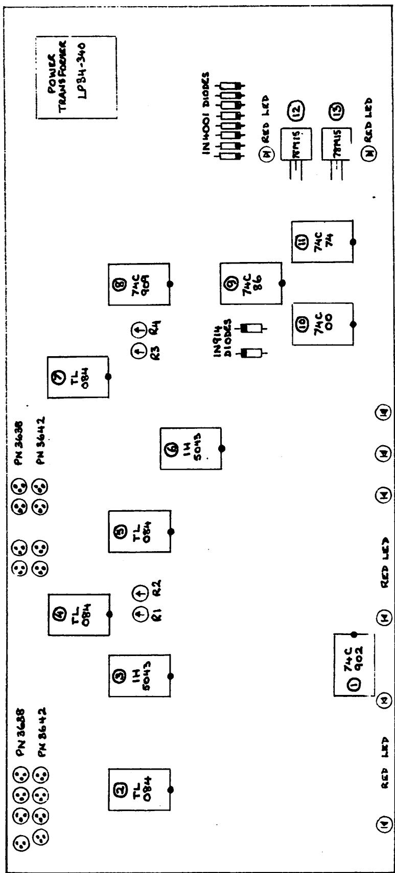
RD770 Monstermat - Semiconductor and internal adjustment drawing (not to scale)
© copyright Eventide Clockworks Inc. 1978
REAR OF CIRCUIT BOARD
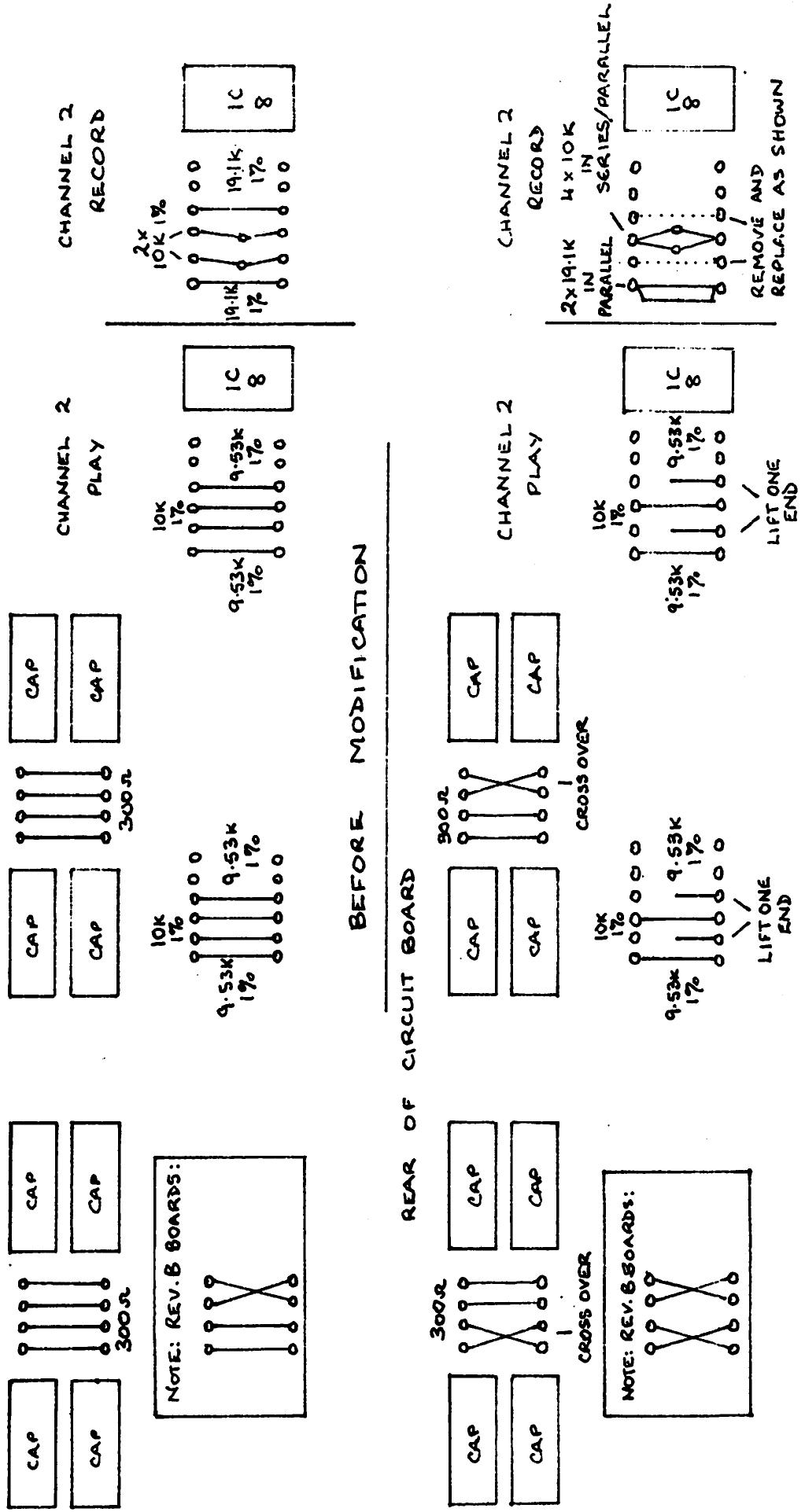
RD770 MONSTERMAT MODIFICATION TO DEFEAT THE STEREO MATRIX
Eventide
the next step
digital delay lines instant flangers
omnipressors harmonizers
monstermats
EVENTIDE CLOCKWORKS, INC. • 265 WEST 54TH STREET • NEW YORK, N.Y. 10019 • 212-581-9290





- EVENTIDE
- RD
- MONSTERMAT
- MONO-STEREO
- MATRIX UNIT
- INSTRUCTION MANUAL
- LIMITED WARRANTY
- SHIPPING
- FOREIGN SHIPMENTS
- EVENTIDE CLOCKWORKS INC
- WARRANTY REGISTRATION FORM MODEL RD770 MONSTERMAT
- CONNECTION INSTRUCTIONS
- CHANNEL 1 IS ALWAYS REPRODUCE
- RECORD ALIGNMENT (MATRIX SECTION)
- RECORD ALIGNMENT (DBX CARDS)
- REPRODUCE ALIGNMENT (MATRIX SECTION)
- REPRODUCE ALIGNMENT (DBX CARDS)
- ALIGNMENT TEST SET-UP PROCEDURE
- DIGITAL DELAY LINES INSTANT FLANGERS
- OMNIPRESSORS HARMONIZERS
- MONSTERMATS
Brand : EVENTIDE
Model : RD770 Monstermat
Category : Professional audio equipment