
TALOS 20K4T - Audio Amplifier FBT - Free user manual and instructions
Find the device manual for free TALOS 20K4T FBT in PDF.


| Product Type | Audio Amplifier |
| Brand | FBT |
| Model | TALOS 20K4T |
| Number of Channels | Four |
| Total Power Output | 20,000 Watts RMS |
| Amplifier Topology | Proprietary 5th generation FBT Class D |
| Digital Processing Resolution | 40 bit |
| Sample Rate | 96 kHz |
| Input Types | Analog, AES3, Dante (optional) |
| Control and Monitoring | Ethernet, volt-free relay, contact closure port |
| Energy Saving Modes | Standby and deep sleep with auto-sleep timers |
| Cooling | Variable speed fans, front-to-back airflow |
| Air Filtration | Washable media, replaceable without tools |
| Mains Input Voltage Range | 85V to 240V (auto-configuring) |
| Mains Input Connector | Neutrik 32A PowerCon |
| Audio Output Connector | Neutrik Speakon |
| Rack Mount | 19-inch 2U (88mm) with handles |
| Net Weight | 12.5 kg (27.5 lbs) |
| Protection Features | VX limiter, Tmax thermal limiter, Xmax excursion limiter |
| DSP Features | LIR linear phase crossover, FIR linear phase EQ |
Frequently Asked Questions - TALOS 20K4T FBT
User questions about TALOS 20K4T FBT
0 question about this device. Answer the ones you know or ask your own.
Ask a new question about this device
Download the instructions for your Audio Amplifier in PDF format for free! Find your manual TALOS 20K4T - FBT and take your electronic device back in hand. On this page are published all the documents necessary for the use of your device. TALOS 20K4T by FBT.
USER MANUAL TALOS 20K4T FBT
GENERAL INFORMATIONS
TALOS 20K4 T Manual
Version : 1.12 EN - 06/2022_rev.21-05-24 Code: 45686
Keep this document in a safe place so that it is available for future reference.
We recommend you to regularly check the FBT website for the latest version of this document.
When reselling this product hand over this document to the new owner.
FBT Elettronica SpA - 62019 Recanati (Italy)
www.fbt.it - info@fbt.it
TALOS 20K4 T
GENERAL INFORMATIONS .... 3
SAFETY INSTRUCTIONS....6
COMPLIANCE 8
For customers in Europe 8
For customers in Canada 8
For customers in the USA 8
THANKS AND UNPACKING 9
Unpacking the TALOS 20K4 T Amplifier....9
INSTALLATION INSTRUCTIONS....10
Mechanical intallation 10
AC Power Connection 10
Important....10
INTRODUCTION AND KEY FEATURES 11
User guide 11
Introduction 11
Key features....11
Drive modules 12
Overlays....12
Lir linear phase crossover filtering....12
Fir linear phase equalisation....12
AUDIO CONNECTIONS 13
Input Connections 13
Using unbalanced connections 13
Amplifier Output Connections 13
Load Matching 13
PANEL LAYOUTS....14
OPERATION 16
Starting up the unit 16
Overview of modules presets component and snapshots 16
Navigation 16
The Home Page....16
Drive Modules 17
Drive Module Presets 17
Component Presets 17
Factory Module Presets 17
Storing Module Presets 17
Recalling components....17
INPUT....18
AES3 inputs 18
Networked audio (dante) inputs....18
Gain and polarity .... 18
Delay....18
Hig pass filter....18
Parametric equalisation....18
Fire shelving eq....18
Parametric filters 18
Routing....18
OUTPUT 19
Gain and Polarity 19
Delay 19
High and Low pass Filters 19
LIR Crossover Filtering 19
Parametric Equalisation and All-Pass Filters 19
Limiters 19
VX Limiter 19
Tmax Thermal Limiter 20
Xmax Excursion Limiter 20
Bridge 20
Routing 20
Driver 20
UTILITY PAGES 21
Screen Contrast 21
Stereo Linking 21
Current Ethernet IP Address 21
IP Mode 21
IP Static....21
Store Snapshot....21
Recall Snapshot....21
Bandwidth Units 21
Aux Style....21
ECO....21
External Breaker Protection (EBP) 21
ETHERNET 22
Ethernet configurations 22
DHCP 22
AUTO-IP 22
Static-IP 22
IP Troubleshooting 22
SNAPSHOTS....23
Snapshots 23
AUX PORT 24
AUX Port 24
LATENCY DELAY 25
Input/Output Latencies 25
Processing latencies....25
SECURE MODE 26
Secure Mode 26
Overlay Flush 26
PROTECTION SYSTEMS....27
Protection Systems 27
Summary of Protection Indication 27
Incident Reporting 27
Fault Relay 27
Performance Logging 27
PROCESSING BLOCK DIAGRAM....28
MENU MAP 29
Input menu map 29
Utility menu map 29
Output menu map 30
EQ AND FILTER RESPONSE GRAPHS 31
TECHNICAL SPECIFICATIONS 32
General....32
Audio 32
Digital processing 32
Power output....32
Power supply 32
Protection systems....33
Monitoring and logging 33
Oem features....33
Options 33

CAUTION
RISK OF ELECTRIC SHOCK DO NOT OPEN
DO NOT EXPOSE TO RAIN OR MOISTURE
ATTENTION
RISQUE DE CHOC ELECTRIQUE NE PAS ENLEVER
NE PAS EXPOSER A LA PLUIE NI A L'HUMIDITE

- Read these instructions.
- Keep these instructions.
- Heed all warnings.
- Follow all instructions.
- Do not use this apparatus near water.
- Clean only with dry cloth.
- Do not block any ventilation openings. Install in accordance with the manufacturer's instructions.
- Do not install near any heat sources such as radiators, heat registers, stoves or other apparatus (including amplifiers) that produce heat.
- Do not defeat the safety purpose of the polarized or grounding type plug. A polarized plug has two blades with one wider than the other. A grounding type plug had two blades and a third grounding prong. The wide blade or the third prong are provided for your safety. If the provided plug does not fit into your outlet, consult an electrician for replacement of the obsolete outlet.
- Protect the power cord from being walked on or pinched particularly at plugs, convenience receptacles and the point where they exit from the apparatus.
- Only use attachments / accessories specified by the manufacturer.
- Use only with the cart, tripod, bracket or table specified by the manufacturer, or sold with the apparatus. When a cart is used, use caution when moving the cart / apparatus combination to avoid injury from tip-over.
- Unplug this apparatus during lightning storms or when unused for long periods of time.
- Refer all servicing to qualified service personnel. Service is required when the apparatus has been damaged in any way, such as power-supply cord or plug damaged, liquid has been spilled or objects have fallen into the apparatus, this apparatus has been exposed to rain or moisture, does not operate normally, or has been dropped.

SAFETY WARNING
Do not remove any covers, loosen any fixings or allow items to enter any aperture.

SAFETY WARNING
The rear of the product may get hot. Avoid direct skin contact during operation and for at least 5 minutes after power has been isolated.

SAFETY WARNING
The product must only be positioned at floor level when operated in a horizontal position

CAUTION
RISK OF ELECTRIC SHOCK DO NOT OPEN
DO NOT EXPOSE TO RAIN OR MOISTURE
ATTENTION
RISQUE DE CHOC ELECTRIQUE NE PAS ENLEVER
NE PAS EXPOSER A LA PLUIE NI A L'HUMIDITE

The product must only be positioned at floor level when operated in a horizontal position.
FOR CUSTOMERS IN EUROPE
This product complies with both the LVD (electrical safety) 73/23/EEC and EMC (electromagnetic compatibility) 89/336/EEC directives issues by the commission of the European community.
Compliance with these directives implies conformity with the following European standards:
• EN62368-1 - Product safety
• EN55032:2015 - EMC emissions
• EN55035:2018-01 - EMC immunity
This product is intended for the following electromagnetic environments: E1, E2; E3 & E4.
THIS PRODUCT MUST BE EARTHED. Use only a flexible cable or cord with a green and yellow core which must be connected to the protective earthing terminal of a suitable mains plug or the earthing terminal of the installation. The cord must be a maximum of 2m long, have a 2.5mm2 CSA, a 300/500V rating and comply with EN50525-2-11 / H05W-F.
THIS PRODUCT IS DESIGNED FOR PERMANENT INSTALLATION.
It must be fitted in to a 19" rack enclosure and not operated unless so installed. The rack enclosure should be open at the front and back to allow free ventilation and movement of air through the product.
FOR CUSTOMERS IN CANADA
This product complies with CA /CSA C22.2 No.62368-1 3 rd Edition
THIS PRODUCT MUST BE EARTHED. Use only a flexible cable or cord with a green or green / yellow core which must be connected to the protective earthing terminal of a suitable mains plug or the earthing terminal of the installation. The cord must be a maximum of 6' long, be 14AWG, have a rating SJ, SJT, SJE or 300/500V H05W-F and be marked VW-1.
THIS PRODUCT IS DESIGNED FOR PERMANENT INSTALLATION. It must be fitted in to a 19" rack enclosure and not operated unless so installed. The rack enclosure should be open at the front and back to allow free ventilation and movement of air through the product.
DECLARATION OF CONFORMITY WITH CANADIAN ICES-003
This Class B digital apparatus complies with Canadian ICES-003.
This product complies with UL62368-1 3 th Edition.
THIS PRODUCT MUST BE EARTHED. Use only a flexible cable or cord with a green or green / yellow core which must be connected to the protective earthing terminal of a suitable mains plug or the earthing terminal of the installation. The cord must be a maximum of 6' long, be 14AWG, have a rating SJ, SJT, SJE or 300/500V H05W-F and be marked VW-1.
THIS PRODUCT IS DESIGNED FOR PERMANENT INSTALLATION. It must be fitted in to a 19" rack enclosure and not operated unless so installed. The rack enclosure should be open at the front and back to allow free ventilation and movement of air through the product.
DECLARATION OF CONFORMITY WITH FCC RULES
FBT Elettronica S.P.A. declare under our sole responsibility that this family of devices, complies with Part 15 of the FCC Rules. Operation is subject to the following two conditions: (1) this device may not cause harmful interference, and (2) this device must accept any interference received, including interference that may cause undesired operation.
FEDERAL COMMUNICATIONS COMMISSION NOTICE
An example of this equipment has been tested and found to comply with the limits for a Class A digital device, pursuant to Part 15 of the FCC Rules. These limits are designed to provide reasonable protection against harmful interference.
This equipment generates, uses, and can radiate radio frequency energy, and if not installed and used in accordance with the instructions, may cause harmful interference to radio communications. However, there is no guarantee that interference will not occur in a particular installation. If this equipment does cause harmful interference to radio or television reception, which can be determined by turning the equipment off and on, the user is encouraged to try and correct the interference by one or more of the following measures:
- Reorient or relocate the receiving antenna.
- Increase the distance between the equipment and the receiver.
- Connect the equipment to an outlet on a circuit different from that to which the receiver is connected.
- Consult the dealer or an experienced radio/TV technician for help.
FCC Caution: Any changes or modifications not expressly approved by the party responsible for compliance could void the user's authority to operate this equipment.
Thank you for choosing a TALOS 20K4 T Advanced System Amplifier for your application. Please spare a little time to study the contents of this manual, so that you obtain the best possible performance from this unit.
All FBT products are carefully engineered for world-class performance and reliability.
If you would like further information about this or any other FBT product, please contact us. We look forward to helping you in the near future.
UNPACKING THE TALOS 20K4 T AMPLIFIER
After unpacking the unit please check carefully for damage. If damage is found, please notify the carrier concerned at once. You, the consignee, must instigate any claim. Please retain all packaging in case of future re-shipment.

MECHANICAL INSTALLATION
The Talos 20K4 T Amplifier is designed to be mounted in a standard 19" rack enclosure.
Where the amplifier is used in a fixed installation, as long as the bottom unit is supported and there are no gaps between units, it is acceptable to use only the front panel 19" rack holes when fitting it in a standard rack enclosure. If the amplifier is mounted in a mobile rack it is important that the rear is supported with a rear rack mounting kit (part number ZA1182). Damage caused by insufficient support is not covered by the warranty.
To prevent damage to the front panel it is recommended that plastic cups or washers are fitted underneath the rack mounting bolt heads.
It is possible to mount multiple Talos 20K4 T amplifiers without ventilation gaps between them but it is essential that an unobstructed flow of clean air is available from the front of the unit to the rear. It is important that neither the air intakes on the front of the unit or the exhaust vents at the rear are covered. Steps must be taken to ensure that hot air does not continually circulate through the amplifiers from the back of the rack to the front.
The amplifier should never be exposed to rain or moisture during operation or storage. If the unit does come into contact with moisture, remove the AC power cord immediately and leave it in a dry and warm location to dry out.
Note that when any equipment is taken from a cold location into a hot humid one, condensation may occur inside the device. Always allow time for the equipment to attain the same temperature as its surrounding environment before connecting the AC power cord.
AC POWER CONNECTION
The amplifier utilises a 32A Neutrik PowerConTM type locking AC power connector. Use only an AC power cord with a correctly terminated PowerConTM type connector to make the connection to the mains power supply.
The amplifiers are designed to operate on 50/60 Hz AC power. The power supply sections automatically configure themselves for either 115V or 230V nominal voltage at turn on. The amplifiers will operate over an extended range of supply voltages (please refer to the technical specifications).
Note that whilst the amplifier will operate correctly at voltages indicated, the specified output power will only be achieved when operating with the stated nominal voltages.
IMPORTANT
It is the responsibility of the user to ensure that dirt, liquids and vapour from theatrical smoke and fog machines is not ingested by the amplifier.
Damage so caused is not covered by the manufacturer's warranty.
AC Power Connection
USER GUIDE
This user manual gives a progressively more detailed description of the functions of the FBT TALOS 20K4 T. A single page quick reference guide is provided for those users who are experienced with this type of equipment and just need to know how to 'drive' the front panel. A detailed explanation of the front and rear panel controls and indicators is contained in the next section.
The final section describes each individual function or feature with annotated images explaining its use. Where appropriate, the graphical display is shown to further elaborate on the units operation.
To complete the manual a reference section is included, describing the technical performance of the device complete with graphs of filter responses.
INTRODUCTION
The TALOS 20K4 T Amplifier represents current state-of-the-art technology in several areas. This product is the result of several years of research, from which many advances in switched mode power technologies and ever finer detail in signal processing have stemmed. Taking advantage of the latest advances in analogue to digital conversion technologies, the unit achieves performance levels among the very best that engineering permits.
Below is a list of key features, followed by some information on the major advanced features of the product.
KEY FEATURES
- Four channels of sonically pure Class D amplification
- Very high power density packs four channels and 20kW into just 2U of rack space
- Packed with robust protection and monitoring systems to keep the show going
- External Breaker Protection (EBP) limits the current draw to prevent breakers opening
• FBT minimal signal path design - Class leading sonic performance achieved by the use of state of the art Amplifier technologies and highly advanced DSP algorithms
- 96kHz sampling frequency provides for a nominally flat response beyond 40kHz.
- Rotary encoders, illuminated buttons and graphical display provide a rapid, intuitive and user-friendly control interface
- High speed Ethernet communications supporting DHCP, static-IP and auto-IP and direct connection to a computer without the need for a router or a switch
- Powerful Drive Module concept, abstraction from device centric to speaker based control
- Innovative Component Presets to allow individual outputs to be used for selected drivers of a loudspeaker system
- Twelve layers of Parameter Overlays for trouble-free Grouping
- Unique VX limiter providing dynamic control for passive 2-way enclosures
- Unique LIR linear phase crossover shapes giving FIR-like performance without the drawbacks
- Linear phase HF system EQ profiling which provides perfect integration between enclosures
- Innovative excursion control limiter with sliding High Pass Filter; limits only the damaging low frequencies
- Transducer thermal modelling provides regulation limiters, addressing long term overload
- Overshoot limiter governs amplitude of transient signals retaining average power whilst constraining peak energy
• Dante audio networking with AVB upgrade path - AES3 inputs
DRIVE MODULES
TheTALOS 20K4T processor has a new way of ordering and grouping channels in order to give a more speaker-based approach to controlling, designing and recalling speaker configurations; these are called Drive Modules. A Drive Module is the Processing provided by one Input DSP Block, and a number of Output DSP Blocks, which are associated with one-a-nother by means of routing. For example, if Input DSP Block B is routed to Outputs 3 and 4, then this is a 2-way Drive Module with Input DSP Block B forming the 'Master' control, and Output DSP Blocks 3 and 4 providing the driver-related control. Overall, this forms the processing typically for one loudspeaker sub-system. The System Engineer Drive Module control panel for this sub-system may then be used for control and monitoring of the associated speaker.
Drive Modules may be included in Module Groups, which use the Parameter Overlay feature in the Device to achieve trouble-free Grouping in the System Engineer application.
The Presets in the Device are Drive-Module centric, and are used to configure individual Drive Modules rather than the whole device.
Importantly, Drive Modules move the focus away from the processing device, and onto the loudspeaker systems.
Component Presets allow the Drive Module Presets to be broken apart, allowing any output to be used for any component within a Drive Module Preset (i.e. any driver in a loudspeaker subsystem).
See Overview of Modules
OVERLAYS
When the Device is used in Modules view in System Engineer, this allows the modules to be grouped into Overlay Groups. These groups allow various Input (master) parameters to be adjusted in all modules in that group, whilst maintaining independent parameter values across each group. This is achieved in the device by combining the parameters for all the layers for a given section (Gain Delay, EQ etc.). When an Overlay parameter is active, the Overlay indicator will become illuminated. The combined Gain or Delay etc. associated with a given section is shown on the module panel in System Engineer, within square brackets [ ] under the Delay and Gain for each input channel. The combined EQ curve is shown in an olive colour. The Input Mute button in System Engineer will flash if an overlay mute is active. On the device, the presence of an active overlay is generally indicated by square brackets “[]” after the parameter value on the display. An input overlay mute is indicated on the mute/clip indicator for that channel flashing. Note that overlay parameters cannot be adjusted on the Device itself; these can only be controlled by the System Engineer application. However, overlay parameters may be removed on the device – see Overlay Flush.
The Device also includes a new type of crossover filtering “Linear Impulse Response” (LIR) crossover filtering, which results in a Linear Phase crossover that has a constant delay regardless of frequency (unlike other types of crossover which delay different frequencies to a different extent, thus smearing the arrival time). The LIR crossover can thus be described as having a flat Group Delay response, and thus entirely free of Group Delay Distortion. The shape of the LIR crossover filter is quite similar to a 4th order or 24dB/Oct Linkwitz-Riley filter, and maintains zero phase difference between the adjacent bands across the crossover region to keep the polar response rock steady.
FIR LINEAR PHASE EQUALISATION
The Input High-Shelf Equalisers use Finite Impulse Response (FIR) filtering to produce Linear Phase equalisation; that is all frequencies are delayed by the same amount, perfectly preserving the transient response. This can also be important in applications where different amounts of EQ are applied to different parts of a speaker cluster, such as to add 'Throw' EQ boost so that parts of cluster which are throwing further can have HF absorption correction added. If this EQ is not linear phase, then the zones where the speakers combine may suffer frequency response anomalies.
INPUT CONNECTIONS
For each input channel there is a female XLR input connector. Even channel numbers are for Analogue inputs only. Odd channel numbers are either for Analogue inputs (when in Analogue input mode) or for AES3 input pairs (when in AES3 input mode).
The HOT, + or 'in phase' connection should be made to pin 2 of the XLR connector.
The COLD, - or 'out of phase' connection should be made to pin 3 of the XLR connector.
Pin 1 of the XLR connectors is internally connected to the chassis. The shield of the input cable should always be connected Pin 1 of the XLR to ensure that EMC performance and regulations are met.
Input XLR balanced connection

USING UNBALANCED CONNECTIONS
Please note that the use of unbalanced connections is not recommended, however when connecting the amplifier to an unbalanced audio source, the signal conductor should be connected to XLR pin2. The 'Cold' conductor or cable screen should be connected to XLR pin 1 with a short connection made between pin 1 and pin 3.
Input XLR unbalanced connection

AMPLIFIER OUTPUT CONNECTIONS
The amplifier is fitted with one SpeakonTM connector per amplifier channel. The appropriate conductor terminations are shown below and on the rear panel of the unit.
Amplifier output connections

The SpeakonTM connector for amplifier channel 1 carries the output for amplifier channels 1 and 2. Similarly, the SpeakonTM connector for amplifier channel 3 carries the output for amplifier channels 3 and 4. This can be useful for making a connection to two loudspeakers with one 4-core cable (i.e. Bi-Amp):
Amplifier output connections - Bi Amp

In addition, the channel 1 or channel 3 connector can also be used if the pair of amplifier channels is being operated in bridged mode.
Amplifier output connections - Bridge

More than one speaker can be connected to each channel provided the total impedance per channel is not less than 2 ohms. In bridged mode the minimum total impedance should not be less than 4 ohms.
LOAD MATCHING
Each output of the device can be optimised to drive either a low impedance load (e.g. 2, 4 or 8 Ohms), or a Constant Voltage (C.V.) such as 70V LINE or 100V LINE etc using the Load parameter in the Output menu. There are several C.V. settings (25V, 70V and 100V Line) which determine the maximum RMS voltage that the amplifier will produce. Select the one which is appropriate for the installation. A number of low impedance settings (depending on the model) are also available. Although it is not critical that this setting matches the impedance of the connected load, this will maximise the power that is available for the load.

- Power Switch: Applies mains power to the device. If the device has entered Sleep mode, it may be woken up again either from the Po dWare application, or by switching this switch off, then on again.
- Input Signal Indicators: A set of five indicators show "Sig", "-12", "0dBu", "+6" and "+12" and "Clip (mute)" for each of the DSP inputs "A" "B" "C" "D". The signal present Indicators operate at approximately -40 dBu. The "0dBu" indicators are intended to show nominal operating level and can also be useful for setting system gain structure. The Clip/mute Indicators- warn the user of input overload and operate at 1dB before clip. This indicator also shows a muted input
- Menu Buttons: The re are three buttons to determine which section of the device to view or edit. The
- Page Selection Buttons: When one of the buttons ,
- Graphical Display: When the device is switched on, it will show the Home screen. This provides a useful overview of channel allocation and Drive Module presets. The screen contrast can be changed by pressing the
button to navigate to "Screen" and using the encoders to change the percentage; this can also optimise the viewing angle. In most pages the currently selected channel and parameter information is displayed on the upper part of the screen and the parameter value on the lower part of the screen. - Parameter Encoders: Two velocity sensitive parameter encoders are used to adjust parameters shown on the display. Up to three parameters at a time are displayed on the screen. The parameter name is shown above the parameter value in each of the three screen sections. Use SELECT to highlight the parameter, then ADJUST to change it.
- Status Indicators: The “OVERLAY” indicator shows when there are parameters active on a group layer, which the user cannot access through the front panel of the device (see Overlay Flush). The “NETAUDIO” indicator shows that a networked digital audio card is installed and routed (Such as Dante™). The “ONLINE” indicator has three states: Off – the unit is offline and not connected to a computer or network. Flashing- the unit is searching for an IP address; if the unit does not find a n IP address the unit will assign itself an IP address automatically and the indicator will stop flashing. On- the uni t is online and connected with software. IP settings can be viewed or changed within the
pages. The “AES3 IN ” indicator illuminates when one or more of the inputs is using an AES3 source. - Bridge Indicator: This will illuminate when the channel pair is in Bridge mode. The controls for the left channel of the pair will determine the settings. See Bridge Mode
- Mute Buttons: DSP output mute status is indicated and controlled by and illuminated button for each channel. These flash when the entire unit is muted from the AUX port or from System Engineer Mute-All, or if this channel has been muted by the protection systems.
- Amplifier Indicator: This indicates when the amplifier protection systems are reducing the gain to keep the parameters of the a multiplier within specification, or that the channel is clipping.
- Driver Indicator: This indicates a signal 6dB higher than the limiter threshold, or when the threshold of the excursion limiter has been exceded, or when the thermal limiter is active, protecting against long term thermal stress. Please note that because of the long release time of the thermal limiter, this indicator may remain illuminated for several seconds after signal on that channel is reduced.
- Limiter Indicators: The output indicators shows the status of the limiter and output level. The
indicator shows signal presence and will illuminate when a signal is present in the output. The second indicator <-6dB> shows that the signal has reached 6dB below the limiter threshold. The third indicator indicates that the threshold of that output channel has been reached.

- Loudspeaker Connectors: The amplifier SpeakonTM outputs. Connect the loudspeaker to the 1+ and 1- terminals. CH1 also carries the (duplicate d) loudspeaker output for channel 2 on terminals 2+ and 2-. Similarly, CH3 carries the loudspeaker output for c channel 4 on terminals 2+ and 2-. For Bridged mode, use terminals 1+ and 2+ of either CH1 or CH3.
- Audio Input Connectors: All audio connections are fully balanced and wired: pin-1 to ground (as required by the AES48 standard), pin-2 hot & pi n-3 cold.
- AES3 Audio Input Conne ctors: For inputting Digital Audio signals. The Input is fully balanced and wired: pin-1 to ground, pin-2 data+ & pi n-3 data. The Link connector allows a buffered AES3 signal to be passed on to another device.
- Networked Audio Ports: The device has the option for networked audio ports; if none are required a blanking plate will be fitted. There are several options for networked audio including Dante™. For a full list please consult your vendor.
- Ethernet Communications Port: The device may be controlled entirely from another controller, typically a Personal Computer, running an application that is compliant with the ObCom standard such as System Engineer. Connection will normally be made to the controller via this Ethernet port connector. This port is also used for updating the firmware in the unit.
- Auxiliary Port: The auxiliary port may be configured to recall snapshots or apply muting.
- Relay output: This isolated relay output may be used to indicate abnormal conditions to external monitoring apparatus. See Fault Relay.
- Power Inlet: The unit should be connected to a suitable mains electricity supply using an earthed Powercon connection power lead. The device has a switch mode power supply that is capable of operating with a nominal mains voltage of 100V to 230V, 50/60Hz without re-configuration.
NOTE: The device must be earthed to a suitable power earth; failure to do so may affect performance and/or operation and will invalidate warranty and could be potentially hazardous. Mute Buttons: DSP output mute status is indicated and controlled by and illuminated button for each channel. These flash when the entire unit is muted from the AUX port or from System Engineer Mute-All, or if this channel has been muted by the protection systems.
STARTING UP THE UNIT
When power switch is switched on the unit will go through its start-up cycle, checking all the sub-systems as it does so. Along the way, the screen will inform you of its progress. Once this is complete the display will then show the Home screen indicating drive module configurations.
OVERVIEW OF MODULES, PRESETS COMPONENTS AND SNAPSHOTS
A Drive Module represents a loudspeaker subsystem, and comprises one input channel and a number of output channels, associated with one another by routing. The size of the Drive module is determined by the number of outputs in it. The device may contain up to four Modules.

A Module Preset is a collection of settings (parameters) for a Drive Module of a particular size. The Preset contains a set of parameters for one input and a set of parameters for each of the outputs in the module. When a Module Preset is recalled, it will automatically change the routing between Input DSPs and Outputs, consuming a number of outputs according to the size of the Drive Module. Recalling a Module Preset thus always creates a Drive Module with consecutive outputs.
| Input component parameters | Output component parameters | |
| Output component parameters |
A Component is a collection of settings (parameters) for one (input or output) channel. Any one of the output components in a Module Preset may be recalled to any individual output.

These concepts are depicted in the System Engineer application as in the following example of a 2-way Module:

A Snapshot is a device-wide representation of most of the settings in the device. This is represented as four Input Component numbers, eight Output Component numbers, plus a number of machine-centric settings such as routing and Input/Output Analogue/Digital selection etc.
| Device Settings | Input A component number | Output 1 component number |
| Output 2 component number | ||
| Input B component number | Output 3 component number | |
| Output 4 component number | ||
| Input C component number | Output 5 component number | |
| Output 6 component number | ||
| Input D component number | Output 7 component number | |
| Output 8 component number |
NAVIGATION
Parameter navigation and adjustment on the TALOS 20K4 T is very straightforward. There is no concept of drilling down deeper into hidden menus; every parameter is accessible by simply scrolling across a 'map' of parameter pages which can be thought of as placed on a 2-dimensional grid. Horizontally across the width of the grid are the various channels, and vertically up and down the grid are the parameter pages for each section of processing.
To view a parameter, repeatedly press the desired or
Two encoders allow you to select and adjust a parameter. Often, several parameters will be shown in various zones on the display. To select a parameter for adjustment, turn the right-most encoder such that the parameter you wish to adjust is highlighted. Then turn the leftmost encoder to adjust the value of that parameter. Turning this encoder clockwise will increase the value of a parameter, or anticlockwise will decrease it. The encoders are velocity-sensitive so turning an encoder rapidly will cause the action to 'accelerate', so the value changes more rapidly.

THE HOME PAGE
The Home Page presents an overview of the configuration of the device. It indicates the user-define Device Name at the top, and shows the four Drive Modules. In each Drive Module the top line shows the Input DSP channel ('A', 'B' etc), and the name the user has given to this channel. The bottom line shows the physical input number, and a list of the outputs which are routed from the Drive Module.

DRIVE MODULES
The TALOS 20K4 T Series uses Drive Modules to represent loudspeaker sub-systems. Drive modules result in a less processor-centric and more speaker-orientated system design. A drive module is defined as the processing provided by one Input DSP, and a number of outputs, which are associated with one-another by means of routing. For example, if Input DSP B is routed to outputs 3 and 4, then this is a 2-way Drive Module; input DSP B forming the 'master' control, and output DSP 3 and 4 providing the driver-related control. The Input DSP parameters then control the Drive Module (and thus the speaker sub-system). The Drive Module control panel in the System Engineer application is then used for control and monitoring of this sub-system.
DRIVE MODULE PRESETS
Presets do not change the settings device-wide. Rather, recalling a Module Preset creates a Drive Module by 'consuming' a number of consecutive outputs and setting up routing between the Input the preset was recalled on and those outputs. The parameters in that Drive Module are then set according to the parameters in the components in the Module Preset.
Note however, that modules with non-consecutive outputs can be created by manually manipulating the routing, and then recalling Component Presets to the individual outputs. The resulting system can then be stored in a Snapshot. Such a Module cannot be saved in a Module Preset.
Note: When a Module Preset Recall consumes outputs to construct a module, it treats a pair of Bridged outputs as a single channel, so recalling a 2-way Module Preset will consume 3 output channels if a Bridged pair is encountered. See Bridge Mode
Note: DSP inputs are not the same as physical inputs. The TALOS 20K4 T Series has four audio inputs and four DSP inputs. This is a matrix mixing system where any physical inputs, be they analogue, AES3 or networked audio feeds, can drive any number of DSP inputs.
COMPONENT PRESETS
A Component Preset represents the processing for just one output. Any part of a Module Preset may be recalled to any one output. A Drive Module comprised of parameters which have been recalled to its outputs using Component Preset Recalls can then be saved into another Module Preset provided the outputs remain consecutive (i.e. you have not changed the routing manually). If the routing has been changed manually, then the whole arrangement may be saved into a Snapshot. Also see Snapshots and Recalling Components.
FACTORY MODULE PRESETS
The device may contain a library of Factory Presets designed to suit a range of enclosures.
Factory Presets may contain some parameters that are fixed and hidden from view; the remainder of the parameters are available for user manipulation. The number and type of hidden parameters is dependent on the Factory Preset, typically crossover frequencies, output delay and some EQs are hidden; those settings that are a function of the loudspeaker cabinet design and should not require adjustment for different applications. Factory Presets are locked (as indicated by a 'box' symbol after the Preset name) so they cannot be over-written. The user can, however, store an edited version of a Factory Preset in any free preset location.
In addition to the Factory Presets the device may have further ‘Skeleton Presets’ which will help to create new presets. They can be used to develop settings for any loudspeaker combination and are recalled in the same way as the Factory Presets described above. These Presets are also usually locked but the user can name and store their own edited versions in any free preset location.
STORING MODULE PRESETS
Once a drive module has been created it can be stored by pressing the button until the edited channel is reached, then pressing the down <▼> button until store page is reached. Using "ADJUST" encoder will change the preset number. When the destination preset is reached, pressing the

Note: Storing a Drive Module preset for a module which is not configured with consecutive outputs is not permitted.
Note: When storing a Drive Module preset on the device, Component Names cannot be edited. To change Component names, the Module Preset must be saved in the System Engineer application.
RECALLING COMPONENTS
To recall a Component Preset (to a single output), press the

Also see Snapshots
AES3 INPUTS
In addition to the usual analogue inputs, the Device can also accept AES3 digital inputs. When a DSP input channel is assigned to an AES3 channel, the “AES3” indicator will illuminate. There is no ‘standard’ for the relative gains between Analogue and AES3 so depending on the levels delivered by the audio source, it may be necessary to adjust the digital input gain trims to normalise them. It is possible to adjust the gain of the AES3 input using the Input Route AES3 Gain parameter. For example, to achieve 0dBFS = +18dBu, set the AES3 trim to -2dB. To achieve 0dBFS = +24dBu, set the trim to +4dB.
This device will automatically lock onto any sample rate within the range 28kHz and 108kHz.
NETWORKED AUDIO (DANTE) INPUTS
When the Digital Audio Network option is fitted, it is possible to select any channel(s) as being sourced from this network. To do this, connect the audio network connection to the connection on the rear of the Device, and set the relevant Input Route menu Source parameter to “Dante” (for example.)
When the Digital Audio Network input is installed and routed, the “Net Audio” indicator above the encoders will illuminate. This indicator will come on even if there are no cables plugged into the networked audio port on the Device.
As for the AES3 inputs, it is possible to set the relative gain between an Analogue input and the signals sourced from the Digital Audio Network using the Input Route Dante gain parameter.
The amplifier will automatically select the correct sample rate from the incoming stream.
For other details on the operation of the Digital Audio Network, please refer to the relevant manufacturer's documentation.
GAIN AND POLARITY
The gain page of the input channel selected allows users to increase or decrease the amount of signal going into the selected input. Using the "SELECT" encoder to highlight the Gain value allows the value to be changed by the "ADJUST encoder in 0.2dB steps from -40dB to +20dB. The presence of an active Group Overlay parameter is indicated by the ‘[]’ symbol (See Overlays). This page will also allow users to change the polarity of the selected input from normal to reverse. And to mute the selected channel.
DELAY
The delay page which controls the amount of delay associated with the input channel selected and is adjustable from 0 to 998ms. The delay parameter is adjustable in fine steps at low values; the adjustment becomes progressively coarser as the value increases. The presence of an active Group Overlay parameter is indicated by the ‘[]’ symbol. See Overlays.
HIGH PASS FILTER
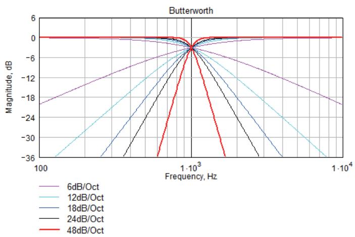
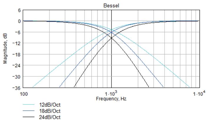
System high pass filtering is provided for the input signal. Filter type is selectable from 1st order, Butterworth, Bessel, Linkwitz-Riley and Hardman. Filter slopes of up to 4th order or 24dB / octave are provided. Not all filter types are available in all slopes. For example 18dB / octave Linkwitz-Riley filters do not exist.
The Hardman type filter is always described by its order as the filter becomes progressively steeper rather than following a linear slope so a dB/octave description is not accurate.
PARAMETRIC EQUALISATION
There are nine stages of equalisation available for each input channel, three shelving filters and six parametric filters.
FIRE SHELVING EQ
The Input High Shelf EQ is implemented using a Finite Impulse Response (FIR) filter, and exhibits a linear phase response; that is all frequencies are delayed by the same amount. This can be important in applications where different amounts of EQ are applied to different parts of a speaker cluster, such as to add 'Throw' EQ boost so that parts of cluster which are throwing further can have HF absorption correction added. If this EQ is not linear phase, then the zones where the speakers combine may suffer frequency response anomalies.
Being a linear phase FIR equaliser, this necessarily introduces some latency delay, which is constant regardless of the settings. However, when the 'Enable' parameter is set to "Off", it is removed from the signal path entirely, so it does not add any latency. In this page you can change the frequency parameter from 2kHz to 20kHz, enable/disable the filter, and change the cut or boost in 0.2dB increments. The presence of an active Group Overlay parameter is indicated by the ‘[]’ symbol being appended to the Gain value (See Overlays). The filter (and its associated latency) can be completely removed by setting the enable parameter to the "Off" position. Note that this EQ can only be used in Module Groups if set to 'On'. Also see Latency Delay.
PARAMETRIC FILTERS
Parametric filters are defined by frequency, bandwidth and gain. The frequency is adjustable over the range from 10Hz to 25.6kHz. The bandwidth shown as Width on the screen, ranges from 0.10 octaves to 5.2 octaves. Bandwidth can be shown and adjusted as Q or Octaves (Oct). Gain is adjusted in 0.2dB increments. The presence of an active Group Overlay parameter is indicated by the ‘[]’ symbol being appended to the Gain value. See Overlays.
Also see Bandwidth Units in Utilities.
ROUTING
Routing allows users to route any physical analogue or digital signal channel to any DSP input. This is effectively a matrix mixing system where all DSPs can be driven from any one input, or from pairs of inputs “1+2”, “3+4”, “1+3”, “1+4”, “2+3” or “2+4”. Summed inputs have 6dB of attenuation so that a sum of largely similar programme material remains at the correct calibrated level. When a sum input is selected, the input DSP meters show the higher of the two inputs so that indication of the onset of clipping of either input is indicated.
GAIN AND POLARITY
The gain page of the output channel allows users to increase or decrease the relative signal gain for the selected output. The Gain value may be adjusted in 0.2dB steps from -40dB to +20dB. This page will also allow users to change the polarity of the selected output from normal to reverse.
DELAY
The delay page controls the amount of delay associated with the output channel selected and is adjustable from 0 to 998ms. The delay parameter is adjustable in fine steps at low values; the adjustment becomes progressively coarser as the value increases.
HIGH AND LOW PASS FILTERS
High pass crossover filtering is provided for the output signal. Filter type is selectable from 1st order, Butterworth, Bessel, Linkwitz-Riley, Hardman and LIR Linear Phase. Filter slopes of up to 8th order or 48dB / octave are provided. Not all filter types are available in all slopes. For example 18dB / octave Linkwitz-Riley filters cannot be selected because they do not exist.
The Hardman type filter is always described by its order as the filter becomes progressively steeper rather than following a linear slope so a dB/octave description is not accurate.
LIR CROSSOVER FILTERING
“Linear Impulse Response” (LIR) crossover filtering gives a Linear Phase crossover which has a constant delay regardless of frequency (unlike other types of crossover which delay different frequencies to a different extent, thus smearing the arrival time). The LIR crossover can thus be described as having a flat Group Delay response, and thus entirely free of Group Delay Distortion, this is exactly the same as can be provided by common FIR filtering but without the complications and disadvantages inherent with the FIR technique.
The shape of the LIR crossover filter is similar to a 4th order Linkwitz-Riley filter, and maintains zero phase difference between the adjacent bands across the crossover region to keep the polar response rock steady. Linear Phase filtering necessarily introduces delay; the laws of physics demand it. To keep this delay to a minimum, it is recommended that more conventional crossover shapes (such as Linkwitz-Riley) are used for the very lowest frequency high-pass edge, particularly if this is less than perhaps 100Hz, which is well below the frequency thought to cause audible ‘Group Delay Distortion’.
This constant delay will depend on the lowest high-pass frequency used in the crossover filters in a given Drive Module.
Also see the section on Latency Delays.
PARAMETRIC EQUALISATION AND ALL-PASS FILTERS
There are ten different EQ filters; two shelving filters and eight parametric filters. Parametric filters are defined by frequency, bandwidth and gain. The frequency is controlled over the range from 10Hz to 25.6kHz. The bandwidth, shown as Width on the screen, ranges from 0.10 octaves to 5.2 octaves. Bandwidth can be shown and adjusted as Q or Octaves (Oct). Gain is adjustable in 0.2dB increments.
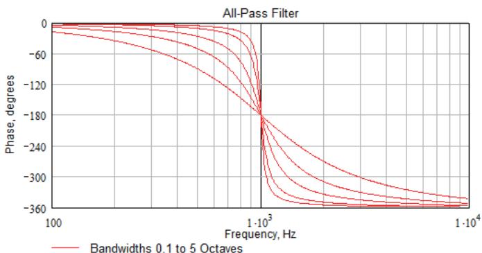
Any of the six Parametric filters can be used as All-Pass filters. When a filter is set to All-Pass mode, the Gain parameter value will show as "AllPass" on the display. This setting may only be engaged or disengaged from the System Engineer PC application. Also see Bandwidth Units in Utilities.
LIMITERS
TALOS 20K4 T includes three limiters in the output signal path. Please note that whilst the Limiters in this product offer protection for amplifiers and drivers, they can never protect from all possible scenarios, therefore FBT is not responsible for any damage which might occur.
VX LIMITER
This is a peak-detecting signal limiter. The VX Mode parameter determines the style of limiter. When Virtual Crossover (VX) mode is off, the limiter is controlled in a conventional manner; the only controls being Threshold and Overshoot.
The Overshoot limiter prevents the signal from exceeding threshold during the attack phase of the main limiter by more than a predetermined amount. The optimal Overshoot setting is usually about 8dB. Lower Overshoot settings will sound progressively 'harder'.
When VX mode is engaged, the user can choose the crossover point of a ‘virtual crossover’, which incorporates two limiters per output so the user can individually limit the drivers in a passive 2-way enclosure using individual thresholds, and optimised attack and release characteristics for each. The Threshold of the second ‘Hi’ limiter is set relative to the threshold of the first ‘Lo’ limiter.
The effect of the VX threshold and split frequency on the Limiter curve can be seen in System Engineer.
This Limiter introduces some delay. In non-VX mode, this delay will depend on the lowest high-pass frequency used in the crossover filters in a given Drive Module. In VX mode, the delay is related to the Split frequency. This delay will be applied to all of the outputs in a given Drive Module to keep them in phase. Also see Latency Delays
TMAX THERMAL LIMITER
The Thermal Limiter is intended to protect the driver against damage due to over-heating. It models the temperature of the driver, and constrains the output signal level in order to keep the average output power below a predetermined limit, applying attack and release characteristics to go some way towards modelling the complex thermal circuit of a driver's voice coil and magnet assembly. Three parameters are available for adjustment:
Threshold – the continuous RMS voltage which the driver should be able to withstand. This is calibrated at the output of the amplifier. The Thermal Limiter can be defeated by setting the Threshold to the maximum "Off" value.
- Attack: The time-constant of the speed at which the driver heats up (in seconds).
- Release: The time-constant of the speed at which the driver cools down (expressed as a multiple of the Attack time).
XMAX EXCURSION LIMITER
The Excursion Limiter protects the driver against excessive linear movement of the cone and voice-coil which could otherwise cause mechanical damage. Since this movement (excursion) is largely related to the inverse of the signal frequency, drivers are prone to being damaged by very low frequencies. This limiter is progressively more sensitive at lower frequencies and, rather than varying the gain to provide the limiting action, it uses a sliding high-pass filter to progressively curtail the low-frequency response, effectively limiting the linear excursion to below the X-max specification of the driver.
To set the limiter up, it is necessary to know the shape of the family of Excursion vs. Frequency curves of the driver for various drive voltage levels. A curve should then be chosen where the slope is high where it passes though the specified X-Max value for the driver. The peak voltage and frequency of this point should then be noted.
The Xmax limiter is usually then set up using just two parameters:
Threshold – the peak voltage of the point arrived at above. This is calibrated at the output of the amplifier. The Excursion Limiter can be defeated by setting Threshold to the maximum "Off" value. Frequency – The frequency at which the above threshold voltage is appropriate.
A further parameter “Min” may also be available for more advanced applications. This allows the increasing limiting action at lower frequencies to level-off below a certain frequency. In most application, this would be left set to its default value of 5Hz.
BRIDGE
When an amplifier pair is set to Bridge Mode, it uses two amplifier channels to drive one loudspeaker with greater power. In this mode, only one set of Output controls is active per pair of amplifier channels since both of the amplifiers in the pair are driven with the same signals, as determined by the channel 1 (or channel 3) controls. Bridge settings should be set up before recalling Drive Module Presets. Module Preset Recall will see a bridged pair of outputs as a single channel.
Bridge Mode is enabled or disabled in the AMP page for a given odd numbered Output. When enabled, the Bridge indicator will be illuminated between the bridged channels.
When Bridged, the partner (even numbered) channel will not show any signal on the limiter meter, and the Mute button will not operate, neither will you be able access any of its parameters for adjustment. The Amplifier protection indicator however will still operate.
ROUTING
Outputs can be driven from any DSP input. This routing is the fundamental means by which Drive Modules are created. Routing should always consume outputs consecutively alphabetically and numerically. However, non-consecutive Drive Modules may be created using manual routing and Recalling Components. See the drive module section of this user manual for more information.
DRIVER
The optimal drive level may be adjusted for a given driver impedance using the Load parameter. See Load Matching.
The live measured impedance value is also shown on the Driver page. Since the device can only measure this when there is a signal, the impedance is indicated as “?” when there is insufficient signal level to perform a measurement.
SCREEN CONTRAST
The Screen page in the “UTILITY” section adjusts the contrast (and optimal viewing angle) of the screen from 0-100% in 1% increments.
STEREO LINKING
Stereo linking is available between DSP Drive Modules A & B and between C & D. Changing a parameter in either of the stereo linked Drive Modules will change the other linked Drive Module. Stereo linking is controlled by the STEREO page in the "UTILITY" menu.
Note: Stereo linking will only work when the linked Drive Modules are of equal size.
CURRENT ETHERNET IP ADDRESS
This may be viewed in the "IP Curr" page of the "UTILITY" menu. This value cannot be edited.
IP MODE
The Ethernet IP address may be automatic "Auto" or may be a fixed static value "Static" as determined by the "IP Mode" page of the "UTILITY" menu.
WARNING - Do NOT use Static mode unless your IT system specifically requires it. Auto mode should always be used where possible since in this mode, the Device can always be 'discovered' by the System Engineer application. When in Static mode, the IP Address will flash on the Home screen.
Also see Ethernet Configurations.
IP STATIC
This allows the Static Ethernet IP address to be adjusted by the three rotary encoders on the IP Static page of the
"UTILITY" menu. This will only have effect when in Static mode.
STORE SNAPSHOT
This page of the “UTILITY” menu allows a Snapshot of the device to be stored. Also see Snapshots.
RECALL SNAPSHOT
This page of the "UTILITY" menu allows a Snapshot to be recalled.
Also see Snapshots and Aux Port.
BANDWIDTH UNITS
This page of the “UTILITY” menu allows the Bandwidth of Parametric Equalisers to be viewed and adjusted in either
Octaves or 'Q'.
AUX STYLE
This page of the “UTILITY” menu allows the action of the Aux port to be viewed and adjusted. Also see Aux Port.
ECO
This page of the “UTILITY” menu allows the device to save power by going into a low power mode when it is not being used.
Standby is a fast mode which saves some energy, but will wake-up very quickly if an audio input is detected. The associated Standby Time parameter allows the amplifier to automatically go into power-save if no audio signal has been detected for a period of time. This function can be defeated by setting the latter control to Manual. FBT would strongly advise leaving it set to automatic however as there is no negative consequence to doing this since 'wake-up' on detecting the presence of an audio input signal is instantaneous.
The Standby Now ‘parameter’ allows the amplifier to be put into standby mode manually when it is not being used.
Sleep is a deep power save mode which saves the most energy, however it will take a small number of seconds for the amplifier to wake-up, and it may only be woken up manually (either from the System Engineer application or by switching the device off then on again). The associated Sleep Time parameter allows the amplifier to automatically go into Sleep mode if no audio signal has been detected for a period of time. This function can be defeated by setting the latter control to Manual.
EXTERNAL BREAKER PROTECTION (EBP)
The Power (“PWR”) utility page provides access to the External Breaker Protection (EBP) feature, which allows the output power to be limited in order to prevent the nuisance tripping of mains circuit breakers or fuses when the amplifier needs to be operated on a mains supply with restricted capacity. Set the EBP value to that of the circuit breaker or fuse to which the amplifier is connected.
ETHERNET CONFIGURATIONS
IP addressing in the Device can be completely automatic; No setup is required.
When first installing and launching System Engineer, the computer Firewall may ask to allow System Engineer to access the network.
NOTE: This must be allowed.
AUTO-IP
The device will initially search for a DHCP server when first switched on (during which time its Online Indicator will be flashing). As it can take up to one minute to establish that there is no DHCP server available, this is the time it may take before Auto IP is entered.
Please be aware that it can also take some time from a computer being switched on in an isolated network (without a DHCP server), or unplugged from a network with DHCP to time out of DHCP searching, so it will not connect immediately to amplifiers that are already using Auto IP. The time it takes before it decides to revert to Auto IP depends on the operating system but it can take several minutes to acquire an Auto IP address.
IP TROUBLESHOOTING
If System Engineer cannot connect to the device:
- Check that the Firewall in the computer will allow System Engineer access to the network.
- If there is no Router in the system acting as a DHCP server, wait 10 minutes (for the computer to acquire the correct IP address) and try again.
Check that the Current IP address in the device is compatible with the IP address of the computer. Generally, the leftmost two sets of 3 digits should be the same.
Always switch on any DHCP server before connecting either the computer or amplifier to the network.
DHCP
There are two primary IP address ranges – one used when there is a DHCP server, and another ('Link Local') where there is no DHCP server (so the Device and the Computer will instead use 'Auto IP' to allocate themselves an IP address). Both the device and the computer must be in the same IP address range. In a local network environment such as an office where there is a DHCP server, both the computer and the Device will be in the DHCP IP address range, and so will connect immediately.
STATIC-IP
If the device or the computer has a static IP address set, System Engineer may not be able to 'see' the device if it is in a different IP Address range (i.e. in a different subnet). Unless there are good reasons it is best to avoid the use of static IP addressing if at all possible.
SNAPSHOTS
A Snapshot may be recalled either via the device User Interface, from the System Engineer application or via the AUX port on the rear of the Device.
The snapshot menu is accessed via the utility pages. Recalling a Snapshot triggers the recalling of a Component to each input and output, and may change other device-wide settings, effectively recalling a processor-wide preset. In addition to being able to recall snapshots from System Engineer and from the Device's front panel, some of the snapshots are also recallable from the auxiliary port. Also see Aux Port.
The parameters inside the Drive Modules are not individually stored in Snapshots. Recalling a Snapshot will merely trigger the recall of the appropriate Input and Output Components, rather than restoring the parameters that were active when the Snapshot was stored. This has the distinct advantage that the library of OEM presets may be updated without having to be concerned about what parameters might have been saved in users Snapshots. It does however require that any existing edits to the parameters in Drive Modules are stored into Drive Module presets before a Snapshot is stored.
Also see Overview Of Modules Components and Snapshots
AUX PORT
The AUX has two inputs, X & Y. These allow simple contact closure devices (relays or switches) or external logic signals to change the state of the amplifier as described below. Connecting an AUX input to ground (the earth symbol) will trigger it; there is no requirement for an external voltage. However, the ports can also be triggered directly by a logic signal as long as the logic 'low' goes below +0.5V. Do not connect systems if their logic 'high' voltage exceeds +24V.
The AUX port may be configured to work in a number of ways by adjusting the Style parameter in the Aux page of the Utility menu:
• None: No operation
- 2+Mute (Event or State): Either Snapshot 1 or Snapshot 2 may be recalled by applying a momentary or static connection to an Aux port terminal, or the device may be muted by Grounding both Aux port terminals
- 3 Snaps (Event or State): Either Snapshot 1 or 2 or 3 may be recalled by applying a momentary or static connection pattern to an Aux port terminals
- 4 Snaps (State): One of the four Snapshots 1,2,3,4 may be selected by applying a static connection pattern to the Aux port terminals
- 3+Mute (State): One of the three Snapshots 1,2,3 may be selected by applying a static connection pattern to the Aux port terminals, or the device may be mute by Grounding both Aux port terminals
The following table shows the action taken for various Aux connection patterns in the various Aux port modes:
| AUX X | AUX Y | 2+Mute Action(State of Event) | 3 Snaps Action(State of Event) | 4 Snaps Action(State) | 3+Mute Action(State) |
| Open | Open | No Change | No Change | Recall Snapshot 1 | Recall Snapshot 1 |
| Gnd | Open | Recall Snapshot 1 | Recall Snapshot 1 | Recall Snapshot 2 | Recall Snapshot 2 |
| Open | Gnd | Recall Snapshot 2 | Recall Snapshot 2 | Recall Snapshot 3 | Recall Snapshot 3 |
| Gnd | Gnd | Mute | Recall Snapshot 3 | Recall Snapshot 4 | Mute |
Some of the above modes allow the AUX Port to be used either in Event mode (whereby a momentary push-button or momentary relay contact closure on one of the AUX lines will cause a Snapshot to be recalled). Or in State mode (where a rotary switch etc. connected to both of the AUX lines selects which Snapshot to use).
Some of the other modes only allow State mode, requiring the connection pattern to persist in order for the Snapshot to be held as the current one.
NOTE: That if the contact closure port is being driven, or if the Aux Style is set to one of the State modes, this will override the snapshot recall setting in the menu (or in System Engineer). Also under these conditions, the snapshot menu items are not accessible, and the Home screen will show the Snapshot number as a reminder.
Also see Snapshots.
All Digital Signal Processing, and conversion between different formats of signal – analogue/digital/network etc., necessarily introduce some delay (latency) to the signal path. Of course, we strive to minimise these latencies. Small as they are, it is sometimes useful to know their precise values. The following describes the principal latencies introduced by various parts of the Device product:
INPUT/OUTPUTLATENCIES
| Analogue Input | 0.385ms | |
| OR | Digital input at 96kHz sample rate | 0.5ms |
| OR | Digital input at 48kHz sample rate | 0.66ms |
| Analogue Output | 0.402ms | |
| OR | AES3 Output | 0.1ms |
| OR | Dante Output | 0.5ms (TBC) |
PROCESSING LATENCIES
(Limited to a minimum of 1.53ms):
| Input HiShelf FIR | 0.6ms (0ms if set to ‘Off’) | |
| LIR Linear Phase crossover | 1.19ms/Fhp(kHz), limited to 30ms maximum * | |
| VxLim Limiter (VX mode off) | 0.12ms/Fhp(kHz), limited to 1.53ms maximum * | |
| OR | VxLim Limiter (VX mode on) | 0.358ms/Fsplit(kHz), limited to 1.53ms max ** |
* This latency figure is calculated using the crossover High-pass frequency (in kHz)
** This latency figure is calculated using the Vx Split frequency (in kHz)
Important tip: The processing latency is constant at 1.53ms unless LIR crossover filters or FIR HiShelf EQs are used, so normally you would just need to add the Input and Output delays to this constant value.
If LIR or FIR are in use, the Processing latency of a Drive Module may increase beyond this figure. The Drive Module Latency may be viewed on the Latency page of the relevant Input DSP channel. This can be accessed by pressing Input then down until the latency page is reached.
When LIR, is used the Vx Limiter can take the overall latency above the 1.53ms. When high pass frequency is set below 40Hz the filter will automatically revert to Linkwitz riley, this is set so that the latency will not exceed 30ms as stated.
Note that the latency reported on the Latency screen in the utilities menu does not include the Input/Output latencies.
When using input FIR filters, LIR or VX Limiters always check the view latency screen to see the latency attributed to that Drive Module.
Example
| Input / Output | |
| Analogue Input | 0.385ms |
| Analogue Output | 0.402ms |
| Processing | |
| Input HIShelf FIR (off) | 0ms |
| LIR Linear Phase corrossover (500Hz) | 2.38ms |
| VxLim Lim (VX mode on, 1kHz Fsplit) | 0.358ms |
| Total | 3.525ms |
Note that the latencies within a Drive Module are equalised among outputs of that Drive Module. That is, padding delay will be automatically added to some outputs such that the total latency is the same in each output of a Drive Module.
This latency equalisation does not extend outside a Drive Module, so Drive Modules are not guaranteed to have the same latency as one-another.
SECURE MODE
When activated, this will disable all the front panel controls so they cannot affect the signal path, making the unit secure against tampering. The only option that is left for user control is snapshot recall. If this is not required then storing the same device state in every snapshot will effectively disable this feature. When in secure mode, the indicators still operate normally. To activate secure mode, press and hold the utility button for 5 seconds. To deactivate, press and hold the utility button for 5 seconds. When in secure mode, this will be shown on the display. Note that the Ethernet communications port is still active in secure mode.
OVERLAY FLUSH
If the device has been used in Module Groups, and still has an active Overlay (as indicated by the Overlay indicator), these can be removed by simultaneously pressing and holding for 5 seconds the Utility and Enter buttons. See Overlays.
PROTECTION SYSTEMS
Comprehensive protection features preserve the longevity of the loudspeaker and amplifier by continuously monitoring several critical parameters, and reducing the gain, or muting the amplifier either temporarily or permanently depending on the nature and seriousness of the fault or misuse. The amplifier will recover and restart if at all possible, but may remain in shut down if a serious fault persists.
Limiters deal with routine over-driving of the amplifier, making sure that the driver(s) are not pushed too hard. The limiter indicators will warn you when the driver is being driven into limit.
Minor faults are dealt with by ‘dimming’ the amplifier, reducing the level to a sufficient degree and for a sufficient time that the amplifier is able to recover gracefully without any user interaction. When the fault condition has passed, the amplifier will recover automatically. When the protection systems are reducing the level, this is indicated by illuminating the left-hand Amplifier channel protection indicator. This will also illuminate when the output voltage is ‘clipping’. This indicator will remain permanently illuminated if the channel has been muted by the protection systems. The Mute button will also flash. This will usually also be indicated by a warning message on the display.
Some types of protection affect all output channels, so you may see the Amplifier indicator illuminated, and the Mute button flash, on every channel.
SUMMARY OF PROTECTION INDICATION
The reasons for the protection indicators illuminating are summarised as follows:
| Amplifier Indicator | Driver Indicator | Notes |
| Limited 6dB over | ||
| Thermal Limitinfg | ||
| Excursion Limiting | ||
| Amplifier Clipping | ||
| Amplifier clip limiting | ||
| Amplifier Current Limiting | ||
| Amplifier VHF limiting | ||
| PSU current limiting | Will show on all output channels | |
| PSU Power limiting | Will show on all output channels | |
| Thermal limiting | Will show on all output channels |
INCIDENT REPORTING
In the System Engineer application, a coloured indicator appears on a Device Bar in the System View which displays the Incident state of the device. The Incident state may be one of three states:
- Red: Fault (The device is faulty in some way and requires attention)
- Yellow: Check (The device may not be performing to its full and should be checked)
- Green: OK (The device is performing well and requires no attention)
Holding your mouse over the Incident indicator for a few seconds will show the current incident level and name.
If an incident is reported you can disable it, and all less serious incidents, by right clicking the bar in System View and selecting ‘Enable/Disable Alarms’. Doing this will show a cross over the Incident indicator and the device will no longer report any Incidents at this level or below.
If any Incidents have previously been disabled they can be enabled by using the right click context menu and selecting ‘Enable/Disable Alarms’ again.
Any active incident will be shown on the display of the device.
A Fault state will also cause the Fault Relay to open. See Fault Relay
FAULT RELAY
Three connections are available via the Phoenix connector for this relay. The schematic representation printed on the rear panel shows the 'idle' state of the relay (when the amplifier is not switched on). When the amplifier is switched on, the relay will normally energise. When a Fault incident occurs, the relay will be de-energised. This will allow either a Fault Incident or a loss of power to be seen as a 'Fault'.
Also see Incident Reporting
PERFORMANCE LOGGING
The System Engineer application allows you to inspect various performance measurements, including various graphs of performance against time, recording events over a period of up to three days. Since the amplifier cannot record any events whilst powered-off, breaks in a log due to power-downs are indicated by a break symbol || in the log.
The events recorded are:
Supply Current: How much current is being supplied to the device via the mains inlet
DC Link Voltage: A voltage which is derived from the mains supply voltage
Thermal Capacity: How much of the available thermal capacity has been used
Driver Current (for each output): The average current being delivered to the driver
Driver Impedance (for each output): The average impedance of the driver Protection Limiting (for each output): How much the amplifier is ‘dimming’ itself in order to protect itself from potential damage.
The data in the log can be exported by right-clicking on the log to launch a context menu, and selecting “copy log data to clipboard”. The data could then be pasted into a spreadsheet for further analysis. Your dealer may ask you to do this is you have experienced a problem.
Alternatively, all of the operational and performance data, including the logs may be collected together into a single file by selecting File > Save Device Diagnostics. Your dealer will be able to read and interpret this data.

INPUT MENU MAP
UTILITY MENU MAP


KEY


UP/DOWN BUTTON PRESS

MENU BUTTON PRESS
OUTPUT MENU MAP




GENERAL
| Number of channels | Four |
| Total power output | 20,000 Watts RMS |
| Input types | Analog, AES3 (Dante as model option) |
| Control, monitoring & alarm | Ethernet, configurable function Volt-free relay and contact closure port |
| Energy saving modes | Standby and deep sleep, both with auto-sleep timers |
| System sleep and wakeup | Front panel switch, network command, contact closure and audio detection |
| Max ambient temperature (full power, no audio limiting) | 40degC (105degF) |
DIGITAL PROCESSING
| Resolution | 40 bit |
| Sample rate | 96kHz throughout |
Special functionality:
| Class leading limiter suite | See the ‘speaker protection systems’ section |
| Hardman crossover filters | Better out of band rejection than Linkwitz-Riley |
| LIR crossover filters | Linear Phase without the compromises of FIR filters |
| FIR Shelving EQ filters | For linear phase filtering |
| Overlays | Twelve additional independent overlays of EQ, Delay and Gain |
AUDIO
| Amplifier topology | Proprietary 5th generation FBT ClassD |
| Amplifier modulation scheme | Low feedback, multiple loop, with feedforward error correction |
| Dynamic range (analog input to speaker output) | >113dBA typ |
| Dynamic range (AES3 or Dante input to output) | >114dBA typ |
| Frequency response | +/- 0.5dB, 5Hz to 20kHz, 4 Ohms -2.5dB, <3Hz to >30kHz, 4 Ohms |
| Total harmonic distortion, THD | <0.05% typ, 1kHz, AES17, 4 Ohms |
| Inter-channel crosstalk (worst combination of channels) | better than -85dBr at 1kHz better than -75dBr at 10kHz |
| Maximum analog input level | +20dBu |
| Analog input sensitivity range for full output | 0dBu to +20dBu, continuously adjustable |
| Analog input | 20k Ohm, electronically balanced |
| Analog link | Directly connected to the analog input |
| Analog ground scheme | AES48 standard compliant |
| AES3 input | Transformer isolated with active cable equalisation for extended range |
| AES3 link | Active signal regeneration with automatic direct bypass to the AES3 input if the unit is unpowered |
| AES3 supported sampling rates | 24kHz to 192kHz (auto locking) |
POWER OUTPUT
| Power specification | RMS output power per channel, all channels driven with continuous program material and a nominal ambient temperature of 40degC / 105degF |
| Crest Factor of 4 (12dB), 2-Ohm nominal load | 5,000W |
| Crest Factor of 2.8 (9dB), 4-Ohm nominal load | 3,000W |
| Crest Factor of 2 (6dB), 8-Ohm nominal load | 1,500W |
| Bridged, per channel pair, 4 Ohm load | 10,000W |
| 25V line (CV) operation, Crest Factor 4 (12dB) | 1250W |
| 70V line (CV) operation, Crest Factor 4 (12dB) | 3500W |
| 100V line (CV) operation, Crest Factor 4 (12dB) | 5,000W |
POWER SUPPLY
| Topology (main power supply) | 3rd generation Series Resonant. |
| Topology (auxiliary and standby supplies) | Low quiescent Eco-Flyback |
| Internally stored energy | >600 Joules |
| Mains input voltage range (automatically configured) | 85V to 240V |
| Mains input frequency range | 47Hz to 63Hz |
| Mains inrush current (max for <10ms) | 6A at 115V, 12A at 230V |
PROTECTION SYSTEMS
Note : Under all circumstances the control and protection systems will endeavor to deliver the maximum power possible for a given set of conditions, applying limiters only in extreme circumstances. Muting will only occur when a dangerous situation is detected, normal operation automatically resuming when the condition clears.
MONITORING AND LOGGING
| Supply current logged vs time | Number of power cycles counted |
| Supply voltage logged vs time | Number of mains brownout events counted |
| Thermal Capacity logged vs time | Fan speeds continuously monitored |
| Each driver current logged vs time | Fan underspeed events counted |
| Each driver impedance logged vs time | Various protection mute events counted |
| Protection limiting for each output logged vs time | Driver Impedance continuously monitored |
OPTIONS
There is internal provision for digital audio network option cards to be factory fitted. Currently FBT support Dante from Audinate.
PHYSICAL
| Cooling | Variable speed fans |
| Airflow | Front to back |
| Air filtration | Washable media, changeable without the use of tools |
| Analog IN and LINK connectors | Genuine Neutrik XLR |
| AES3 IN and LINK connectors | Genuine Neutrik XLR |
| Audio output connector | Genuine Neutrik Speakon |
| Mains input connector | Genuine Neutrik 32A Powercon |
| Dante Primary and Secondary | Shielded RJ45 |
| Relay output & contact closure inputs | Phoenix pluggable terminal block |
| Front panel display (backlit) | Graphical, high contrast, daylight visible. |
| Front panel encoders | Two, indented, velocity sensitive |
| Front panel push buttons | Large, tactile, illuminated |
| LED indicators | Bright, easily differentiated. Enclosure Standard 19” 2U (88mm) with handles and optional rear support system |
| Depth (behind rack ears) | 12.5kg (27.5 |
| Net Weight | 12.5kg (27.5 pounds) |

FBT


- GENERAL INFORMATIONS
- TALOS 20K4 T
- SAFETY INSTRUCTIONS
- COMPLIANCE
- THANKS AND UNPACKING
- INSTALLATION INSTRUCTIONS
- INTRODUCTION AND KEY FEATURES
- AUDIO CONNECTIONS
- PANEL LAYOUTS
- OPERATION
- INPUT
- OUTPUT
- UTILITY PAGES
- ETHERNET
- SNAPSHOTS
- AUX PORT
- LATENCY DELAY
- SECURE MODE
- PROTECTION SYSTEMS
- PROCESSING BLOCK DIAGRAM
- MENU MAP
- EQ AND FILTER RESPONSE GRAPHS
- TECHNICAL SPECIFICATIONS
- CAUTION
- RISK OF ELECTRIC SHOCK DO NOT OPEN
- ATTENTION
- RISQUE DE CHOC ELECTRIQUE NE PAS ENLEVER
- SAFETY WARNING
- FOR CUSTOMERS IN EUROPE
- FOR CUSTOMERS IN CANADA
- DECLARATION OF CONFORMITY WITH FCC RULES
- FEDERAL COMMUNICATIONS COMMISSION NOTICE
- UNPACKING THE TALOS 20K4 T AMPLIFIER
- MECHANICAL INSTALLATION
- AC POWER CONNECTION
- IMPORTANT
- USER GUIDE
- INTRODUCTION
- KEY FEATURES
- DRIVE MODULES
- OVERLAYS
- FIR LINEAR PHASE EQUALISATION
- INPUT CONNECTIONS
- USING UNBALANCED CONNECTIONS
- AMPLIFIER OUTPUT CONNECTIONS
- LOAD MATCHING
- STARTING UP THE UNIT
- OVERVIEW OF MODULES, PRESETS COMPONENTS AND SNAPSHOTS
- NAVIGATION
- THE HOME PAGE
- DRIVE MODULE PRESETS
- COMPONENT PRESETS
- FACTORY MODULE PRESETS
- STORING MODULE PRESETS
- RECALLING COMPONENTS
- AES3 INPUTS
- NETWORKED AUDIO (DANTE) INPUTS
- GAIN AND POLARITY
- DELAY
- HIGH PASS FILTER
- PARAMETRIC EQUALISATION
- FIRE SHELVING EQ
- PARAMETRIC FILTERS
- ROUTING
- HIGH AND LOW PASS FILTERS
- LIR CROSSOVER FILTERING
- PARAMETRIC EQUALISATION AND ALL-PASS FILTERS
- LIMITERS
- VX LIMITER
- TMAX THERMAL LIMITER
- XMAX EXCURSION LIMITER
- BRIDGE
- DRIVER
- SCREEN CONTRAST
- STEREO LINKING
- CURRENT ETHERNET IP ADDRESS
- IP MODE
- IP STATIC
- STORE SNAPSHOT
- RECALL SNAPSHOT
- BANDWIDTH UNITS
- AUX STYLE
- ECO
- EXTERNAL BREAKER PROTECTION (EBP)
- ETHERNET CONFIGURATIONS
- AUTO-IP
- IP TROUBLESHOOTING
- DHCP
- STATIC-IP
- OVERLAY FLUSH
- SUMMARY OF PROTECTION INDICATION
- INCIDENT REPORTING
- FAULT RELAY
- PERFORMANCE LOGGING
- INPUT MENU MAP
- UTILITY MENU MAP
- OUTPUT MENU MAP
- OPTIONS
Brand : FBT
Model : TALOS 20K4T
Category : Audio Amplifier