Dynamix - Modular audio module Make Noise - Free user manual and instructions
Find the device manual for free Dynamix Make Noise in PDF.
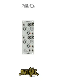


| Product Type | Modular Audio Module |
| Brand | Make Noise |
| Model | DynaMix |
| Synthesis Format | Eurorack 3U |
| Module Width | 10 HP (50.8 mm) |
| Power Consumption | +12VDC @ 55mA, -12VDC @ 45mA |
| Main Function | Two-channel Low Pass Gate, dynamics manager and mixer |
| Level Control | CV input with +8V normalization and manual potentiometer |
| DYNMC Input | Audio-rate side-chain input with attenuverter |
| Signal Input Drive | Pre-gain attenuator with overload characteristic beyond 3:00 |
| Auxiliary Input | For chaining multiple mix modules |
| Sum Output | Mixes both channels and auxiliary input |
| Audio Processing | Simultaneous amplitude and frequency control (VCF/A) |
| Input Coupling | Direct coupled (accepts audio and control voltages) |
| Indicators | Level LEDs for each channel |
| Installation | 10HP Eurorack slot with standard bus board connector |
| Safety Warning | Disconnect power before removing/inserting bus board cables |
| Warranty | 1 year limited warranty |
| Maintenance | Clean with a dry cloth; keep away from moisture |
| Service & Repair | Contact Make Noise technical support for repair or return authorization |
Frequently Asked Questions - Dynamix Make Noise
User questions about Dynamix Make Noise
0 question about this device. Answer the ones you know or ask your own.
Ask a new question about this device
Download the instructions for your Modular audio module in PDF format for free! Find your manual Dynamix - Make Noise and take your electronic device back in hand. On this page are published all the documents necessary for the use of your device. Dynamix by Make Noise.
USER MANUAL Dynamix Make Noise
DYNAMIX


Table of Contents: 2
Limited Warranty: 3
Installation: 4
Overview:----5
Panel Controls: 6
Getting Started: 7
Dynamics Management: 8
Tips and Tricks: 9
Patch Ideas: 10
Make Noise warrants this product to be free of defects in materials or construction for a period of one year from the date of purchase (proof of purchase/invoice required).
Malfunction resulting from wrong power supply voltages, backwards or reversed eurorack bus board cable connection, abuse of the product, removing knobs, changing face plates, or any other causes determined by Make Noise to be the fault of the user are not covered by this warranty, and normal service rates will apply.
During the warranty period, any defective products will be repaired or replaced, at the option of Make Noise, on a return-to-Make Noise basis with the customer paying the transit cost to Make Noise.
Make Noise implies and accepts no responsibility for harm to person or apparatus caused through operation of this product.
Please contact technical@makenoismusic.com with any questions, Return To Manufacturer Authorization, or any needs & comments.
http://www.makenoisemusic.com

About This Manual:
Written by Tony Rolando and Walker Farrell Illustrated by W.Lee Coleman
Electrocution hazard!
Always turns the Eurorack case off and unplug the power cord before plugging or un-plugging any Eurorack bus board connection cable. Do not touch any electrical terminals when attaching any Eurorack bus board cable.
The Make Noise DynaMix is an electronic music module requiring 55 mA of +12VDC and 45 mA of -12VDC regulated voltages and a properly formatted distribution receptacle to operate. It must be properly installed into a Eurorack format modular synthesizer system case.
Go to http://www.makenoisemusic.com/ for examples of Eurorack Systems and Cases.
To install, find 10HP in your Eurorack synthesizer case, confirm proper installation of included Eurorack bus board connector cable on backside of module (see picture below), plug the bus board connector cable into the Eurorack style bus board, minding the polarity so that the RED stripe on the cable is oriented to the NEGATIVE 12 Volt line on both the module and the bus board. On the Make Noise 6U or 3U Busboard, the negative 12 Volt line is indicated by the white stripe.

Please refer to your case manufacturers' specifications for location of the negative supply.
DynaMix is a fast two-channel Low Pass Gate, dynamics manager and mixer, the core of which is derived from our 0-COAST synthesizer. The Level parameter provides simultaneous voltage control over the Amplitude and Frequency content of audio signals, operating as a VCF/A. The DYNMC parameter accepts audio signals and converts them into a signal that may increase or decrease the Level parameter thus allowing for side-chaining and ducking. The summing section is complete with an Auxiliary Input allowing for the chaining of multiple MIX units (modDemix, Optimix and RxMx modules) to create large, non-centralized mixes.
The DynaMix is functionally similar to the Optomix LPG: a fundamental element in the sound of West Coast Synthesis. However, rather than using the Vactrol component that gives the Optomix its characteristic "slow" sound, the DynaMix utilizes transistors in a topology that has more in common with East Coast instruments. This combination of West Coast technique and East Coast circuitry is No-Coast synthesis at its best, allowing the Low Pass Gate to be used in tandem with an extremely-important East Coast synthesis circuit: the ADSR: a 4-stage Envelope generator we call CONTOUR.
As a VCA, the DynaMix has a fast Attack and Decay response, meaning that it turns on and off quickly, allowing for highly-articulated transients. As a VCF, it is a mild, non-resonant Low Pass circuit, acting to gently reveal (or hide) the sharper edges of a sound. The simultaneous loss in high frequency content and reduction in amplitude is similar to the natural loss of energy in idio- and membranophonic instruments.
The DYNMC Input and associated Attenuverter provide a simple form of dynamics management as well as an additional modulation destination that has a non-linear response that is distinct from that of the Level CV Input. When combined with the Signal Input Drive and Level controls, there is great control over how signals are combined.
Panel Controls

-
Channel 1 Signal Input: Direct coupled signal input capable of accepting audio or control signals with a range of around 10Vpp.
-
Channel 1 Signal Input Drive: Input attenuator for associated Signal Input. Unity gain around 1:00. Begins to overload the Dynamic circuit after about 3:00. Attenuates to silence at full counter clockwise.
-
Channel 1 DYNMC Input: Input for DYNMC parameter, accepts audio signals for use as control signals. Also capable of accepting CVs. Normalized to CH. 1 Signal Input, so that with nothing patched, the Channel 1 DYNMC Attenuverter operates as a manual control. Range +/-10V AC or DC.
-
Channel 1 DYNMC Attenuverter: Bipolar attenuator for DYNMC Input. With nothing patched to the DYNMC Input, operates as a manual control. Set to 12:00 when DYNMC parameter not in use.
-
Channel 1 Level Input: Direct coupled CV input for the associated channel amplitude and brightness levels. Normalized to +8V so with nothing patched the associated Channel 1 Level Combo Pot operates as a manual control for Level. Range 0V to 8V DC.
-
Channel 1 Level Combo Pot: Unipolar attenuator for Control Signal Input. With nothing patched to the Level CV Input, operates as a manual control for the Level parameter.
-
Channel 1 Signal Output: Output of the signal applied to the Channel 1 input, as processed by the DynaMix. 10Vpp (depending upon settings and source material).
-
Channel 1 Level LED: Indicates Level parameter, lighting brighter as Level parameter is increased.
-
Channel 2 Signal Input: Direct coupled signal input capable of accepting audio or control signals with a range of around 10Vpp.
-
Channel 2 Signal Input Drive: Input attenuator for associated Signal Input. Begins to overload the Dynamic circuit after about 3:00. Attenuates to silence at full counter clockwise.
-
Channel 2 DYNMC Input: Input for DYNMC parameter, accepts audio signals for use as control signals. Also capable of accepting CVs. Normalized to CH. 2 Signal Input, so that with nothing patched, the Channel 2 DYNMC Attenuverter operates as a manual control. Range +/-10V AC or DC.
-
Channel 2 DYNMC Attenuverter: Bipolar attenuator for DYNMC Input. With nothing patched to the DYNMC Input, operates as a manual control. Set to 12:00 when DYNMC parameter not in use.
- Channel 2 Level Input: Direct coupled CV input for the associated channel amplitude and brightness levels. Normalized to +8V so with nothing patched the associated Channel 2 Level Combo Pot operates as a manual control for Level. Range 0V to 8V DC.
- Channel 2 Level Combo Pot: Unipolar attenuator for Control Signal Input. With nothing patched to the Level CV Input, operates as a manual control for the Level parameter.
- Channel 2 Signal Output: Output of the signal applied to the Channel 2 input, as processed by the DynaMix. 10Vpp (depending upon settings and source material).
- Channel 2 Level LED: Indicates Level parameter, lighting brighter as the Level parameter is increased.
- Auxiliary Input: Direct-coupled signal input to the SUM circuit, allowing for the chaining of multiple DynaMix, modDemix, Optomix, and RxMx units to create large non-centralized mixes. Capable of accepting audio or control signals up to 10Vpp.
- SUM Output: The Sum or mix of all signals processed by the DynaMix. 10Vpp (depending upon settings and source material).
It's a VCA, It's a VCF...
The Low Pass Gate operates simultaneously in the Amplitude and Frequency domains. When a control signal is patched to the Level Input, as it becomes more positive, the Amplitude of the processed signal increases, with the lower frequencies being more quickly amplified than the higher frequencies. As a control signal patched to the Level Input becomes less positive, the Amplitude decreases with the higher frequencies being attenuated much sooner than the lower. The lower frequencies lurk in the spectrum, while higher frequencies are eagerly diminished.
One way to listen to the effect of the DynaMix is to patch a harmonically-rich audio signal, such as a Frequency-Modulated VCO to the Signal Input. Next, set the Level Panel Control to Full counter clockwise. You should hear no sound. Slowly sweep the Level Panel Control to Full Clockwise. Notice as you increase the Level Panel Control, the sound gets both louder and brighter while the Level LED lights orange.
Though this demonstrates the behavior of the circuit, manual manipulation of the Panel Controls are not the best application of the VCF-A phenomenon. For best results, patch an exponentially-shaped Envelope/Control Voltage with a fast Rise or Onset, no Sustain, and a slow Fall or Decay to the Level CV Input. This provides a beautiful example of DynaMix's ability to produce acoustic-like Attack & Decay transients.
Figure 1:

AM Synthesis
Amplitude Modulation is a classic synthesis technique that should not be forgotten! The Dynamix responds accurately to audio rate modulation and is well suited for AM techniques. AM is similar to the ring modulation or balanced modulation techniques the modDemix is typically used for, except the depth of modulation is 50% less. This means there are half the amount of sidebands created. The sidebands are what add harmonic complexity to the signal and having fewer is useful at times where you need to better preserve the fundamental of the signal, for example when trying to create harmonically rich melodic musical note passages. Ring modulation, on the other hand, tends to remove the fundamentals of both "carrier" and "modulator", making its melodic use unpredictable or incoherent.
To hear a example of AM, try tuning two VCOs to a simple interval such as octave or fifth, patch one to the Signal Input and the other to the Level CV Inputs on the DynaMix, and sequence both with the same sequence using a multiple. Depending upon settings of the Level Attenuator and the relative frequencies of the VCOs utilized, it is possible to achieve a range of timbres.
Note: the modDemix may be used for AM as well, but the resulting sounds have more harmonics than the DynaMix due to the nature of the modDemix circuit.
The DynaMix DYNMC Input allows for audio signals to be used as control signals. Audio signals patched to the DYNMC Input are averaged to the point of creating a smooth positive control voltage. The associated DYNMC Attenuverter allows for adding or subtracting these positive control signals from the Level parameter value. The LED is helpful for indicating this action.
Modulating a Channel's DYNMC parameter relative to its Level parameter may introduce Gain Reduction or Gain Expansion based on the setting of the DYNMC Attenuverter, with the Ratio set by the Level parameter. For the most dramatic results, the Level Combo Pot should be set to 1:00 or further CCW. When the Associated DYNMC Attenuverter is set counter clockwise from 12:00, Gain Reduction is achieved. When the Associated DYNMC Attenuverter is set clockwise from 12:00, Gain Expansion is achieved. This depends a great deal upon the source material patched to the channel Signal Input and/ or the DYNMC Input.
The unprocessed output of most VCOs has little effect when patched to the DYNMC Input (or when routed there via the normalization). This is because the unprocessed output of most VCOs has little to no dynamic range. The signal is of constant loudness. There is no audible variation in amplitude to translate into a control signal. By contrast a loop of a percussive instrument played back from an external source will have a great deal of dynamic range that could be translated into an interesting control signal to be used to impart variation in the Level of the signal being processed with the Dynamix.
Keep in mind the DYNMC Input is designed to work with modular level signals of around 10Vpp. To get the most from the DYNMC Input audio signals should be at the modular level.
Even the signal the DynaMix is processing could be used to modulate the dynamics of itself! For this reason, the signal patched to the Signal Input is normalled to the DYNMC Input. Assuming the source material has a wide enough dynamic range, you may achieve gain reduction or expansion by setting the associated DYNMC Attenuverter appropriately.
When it is not desired to use the DYNMC parameter, be sure to set the DYNMC Attenuverter to 12:00 or patch a dummy cable to the DYNMC Input.
Also note that the Signal Input Drive controls are of great use for Balancing the signals patched to the DynaMix with each other and other signals being used in a patch. Both Channel 1 and 2 Signal Input Drive can boost the signal by 55% or cut a signal by up to 100%. The Signal Input Drive is at unity around 1:00. Further clockwise from 1:00 the gain is increased and the input begins to overload after about 3:00 assuming standard modular level signals are utilized. Setting the Signal Input drive to below 1:00 will reduce the gain. The Signal Input Drive is a Pre-Gain and unlike the Level parameter there is no low pass filtering of the signal. This makes it possible to adjust the relative levels of the signals without affecting the timbre.
Processing Control Voltage w/ Audio Signals and More
The Signal Input is Direct Coupled so it is possible to use the Dynamix to process Control Voltages as well. There is both gain and attenuation available at the Signal Input which might be helpful when you need to translate between different systems or modules. The Level parameter provides voltage control over the amplitude of the signal being processed. The frequency domain processing of the DynaMix is tuned to the audio range and thus has little effect upon the lower frequency range of most control signals.
Since the DYNMC Input accepts audio signals for use in controlling the Level parameter it facilitates the uncommon technique of using audio signals to control the depth of control signals being used in a patch for modulation. If control voltage to be processed is patched to the Signal Input and the Level parameter is set to be around 1:00, by patching a dynamic audio signal (one in which there is much change in amplitude over time) to the DYNMC Input and setting the associated DYNMC Attenuverter to be CW of 12:00 you could achieve an increase in modulation depth as the audio signal patched to DYNMC Input gets louder. By setting the associated DYNMC Attenuverter to be CCW of 12:00, you could achieve an decrease in modulation depth as the signal patched to DYNMC Input gets louder. This less often used technique should present many unique patch combination to explore!
-If you have nothing patched to the DYNMC Input, be sure to remember the normalization of the Signal Input to the DYNMC Input. Setting the associated DYNMC Attenuverter to 12:00 or simply patching a Dummy Cable makes certain there is no unwanted influence.
-The DYNMC Input may act as an Accent parameter when utilizing the DynaMix in a sequencing patch. For example, patch your Envelope control signal to the Level Input with the associated Level Combo Pot set to about 2:00 for some attenuation of the Envelope CV. Patch an Accent Gate signal (perhaps from a Clock Divider or a Gate Sequence that is unique from the one driving the Envelope Control Signal) to the DYNMC Input. Steps where the Accent Gate goes "High" are louder. Note: the width of the Accent Gate sequence is also a factor. Shorter Gates and pulses work best.
-The Level and DYNMC parameters respond differently to control signals with the DYNMC Input being non-linear and generally "louder" and the Level being more Linear and faster sounding when patching the same CV to either DYNMC or Level.
-The Signal Input has an associated attenuator that could be used to balance the mix of the channels at the Sum Output without changing the brightness settings made using the Level controls.
-The Signal Input starts to overload when the signal at the input is 10V and the associated attenuator is set beyond about 3:00.
-To get more dramatic overload, run two channels of the DynaMix in series with the Signal Input set to maximum on both channels and the Level parameter set to maximum on the first channel. Patch Channel 1 Output to the Channel 2 Signal Input.
-Side-Chain processing starts by patching an Audio-rate signal with large dynamic range to the DYNMC Input. The DYNMC Input acts as the Side Chain Input with the associated Attenuverter setting the amount of Gain Reduction or Expansion. The Level Combo Pot determines the Ratio, with the best settings typically falling somewhere between 11:00 and 1:00. The resulting sound is soft and squishy and useful for ducking effects.
-When used with an audio signal at the most dramatic settings, the DYNMC Input is also useful for adding harmonics to the signal since there is some feed-through of the audio signal in the form of Amplitude Modulation. The effect is subtle but when combined with the gain reduction or expansion and Input Signal Drive it is possible to create more aggressive sounds.
-The DYNMC inputs are intended first and foremost for use with audio signals. Use with Control Voltage signals is possible and encouraged, but please note that the response is non-linear and only quasi-predictable.
The New Vactrol Free Bongo:
Set up a VCO for Two-Operator FM by applying a Sine wave to its Linear FM Input or using the DPO's FM Bus and patching the resulting waveform to DynaMix's Input. Set the associated attenuator to 4:00. Patch an Exponentially-shaped Envelope CV with a fast Rise or Onset and a slower Fall or Decay and no Sustain to the Level CV Input. Set the associated Level Combo Pot (attenuator) to 1:00. Trigger the envelope CV.


Gate Controlled Crossfader
Use this patch to fade between any two audio or CV sources, flying at the speed of an envelope.
Variation: Gate controlled switch Set Onset and Decay full CCW, use EON and EOC instead of Contour and Mirror Out.
SideChain/Ducking
Gating the Contour opens Dynamix Channel 1 creating an envelope for VCO 2 in order to "duck" Ch2 based on the loudness of the Ch1 output and the setting of the DYNMC input attenuverter.




Brand : Make Noise
Model : Dynamix
Category : Modular audio module