Analog Memory - Electronic musical instrument Make Noise - Free user manual and instructions
Find the device manual for free Analog Memory Make Noise in PDF.
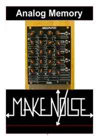


| Product type | Electronic musical instrument module for modular synthesizer |
| Brand | Make Noise |
| Model | Analog Memory |
| Format | Eurorack, 20HP |
| Power consumption | 20mA on +12V rail |
| Storage technology | Mechanically Orbited Carbon (MOC RAM), non-volatile |
| Storage capacity | 20 control voltage values in 4 columns of 5 |
| Output voltage ranges | Top output 0V–8V, other outputs 0V–5.5V |
| Output buffering | Buffered outputs for multiple destinations without level drop |
| Indicators | 4 LEDs showing selected column |
| Programming controls | 20 potentiometers, one per stored value, with bright indicator lines |
| Interface | Compatible with Pressure Points and Pressure Points/BRAINS systems |
| Expandability | Up to 4 Analog Memory modules and 2 BRAINS via CHAIN |
| Included cables | Power cable, EXPAND cable, CHAIN cable |
| Warranty | 2 years limited warranty from date of manufacture |
| Maintenance | Wipe with dry cloth; avoid liquids and physical shock |
| Safety | Use only specified power supply; mind red stripe polarity on cables |
| Repairability | Contact Make Noise for RMA and service; warranty covers defects |
| General information | Retains data even with power off; ideal for storing and recalling control voltage settings |
Frequently Asked Questions - Analog Memory Make Noise
User questions about Analog Memory Make Noise
0 question about this device. Answer the ones you know or ask your own.
Ask a new question about this device
Download the instructions for your Electronic musical instrument in PDF format for free! Find your manual Analog Memory - Make Noise and take your electronic device back in hand. On this page are published all the documents necessary for the use of your device. Analog Memory by Make Noise.
USER MANUAL Analog Memory Make Noise
Analog Memory


Limited WARRANTY:
Make Noise warrants this product to be free of defects in materials or construction for a period of two years from the date of manufacture.
Malfunction resulting from wrong power supply voltages, backwards power cable connection, abuse of the product or any other causes determined by Make Noise to be the fault of the user are not covered by this warranty, and normal service rates will apply.
During the warranty period, any defective products will be repaired or replaced, at the option of Make Noise, on a return-to-Make Noise basis, with the customer paying the transit cost to Make Noise. Please contact Make Noise for Return To Manufacturer Authorization.
Make Noise implies and accepts no responsibility for harm to person or apparatus caused through operation of this product.
Please contact tony@makenoisemusic.com with anyquestions, needs & comments... otherwise go MAKE NOISE.
http://www.makenoisemusic.com
Installation:
The Make Noise Analog Memory is an electronic signal generator requiring 20mA of +12V regulated power and properly formatted distribution receptacle to operate. It is designed to be used within the euro format modular synthesizer system.
Go to http://www.doepfer.de/a100_man/a100t_e.htm for the details of this format.
To install, find 20HP of space in your euro-rack synthesizer system directly above or adjacent to the Pressure Points which will connect to the Analog Memory.
Power Cable:
Confirm proper installation of included power cable on backside of module (see picture below). Once the EXPAND and CHAIN cables are installed, plug the 16pin end power cable into the euro-rack style power distribution board, minding the polarity so that the RED stripe on the cable is oriented to the NEGATIVE 12 volt supply line. This is USUALLY at the bottom. Please refer to your case manufacturers' specifications for location of the negative supply.

Proper installation of included power cable on module. Please note the RED BAND.
EXPAND Cable:
The expand cable has four 10 x 2 female connector on a flat grey cable with one Red Stripe. One end of this cable is attached to the Pin Header on the back of the Analog Memory where it says "Connect to EXPAND."


Orient the Red Stripe Down for easy installation.
Connection to Single Pressure Points

Connect one of the remaining 3 connectors to the 10 pin header on the Pressure Points that is marked "EXPND." You will need to remove all 4 of the small black "jumpers" that are covering the pins of this header before you attach the EXPAND CABLE.
NOTE: Power Cables removed in photo for clarity.
Connecting 2 Analog Memory to 2 Pressure Points

Connect one of the remaining 3 connectors to the 10 pin header on the Pressure Points that is marked "EXPND." You will need to remove all 4 of the small black "jumpers" that are covering the pins of this header before you attach the EXPAND CABLE. Maintain proper orientation of the cable, keeping the Red Stripe DOWN. Connect each Analog Memory to the Pressure Points with which you wish to control it.
Using the provided CHAIN cable, connect the two Analog Memory modules at the 10 pin header marked "CHAIN" at top left on back-side of the module. Maintain proper orientation of the cable, keeping the Red Stripe DOWN at both ends. Analog Memory(s) that are not the that last in the CHAIN will need to have the jumper marked "Close 4 Master" removed.
Please see the Pressure Points manual for details on proper jumper settings for CHAINing Pressure Points, and follow those instructions.
NOTE: Power Cables removed in photo for clarity.
Connecting Analog Memory to Pressure Points/ BRAINS system

Before connecting to the Pressure Points/ BRAINS system, you will need to remove the 4 jumpers along the bottom of the backside of the Analog Memory.
Connecting 1 Analog Memory to Pressure Points/ BRAINS
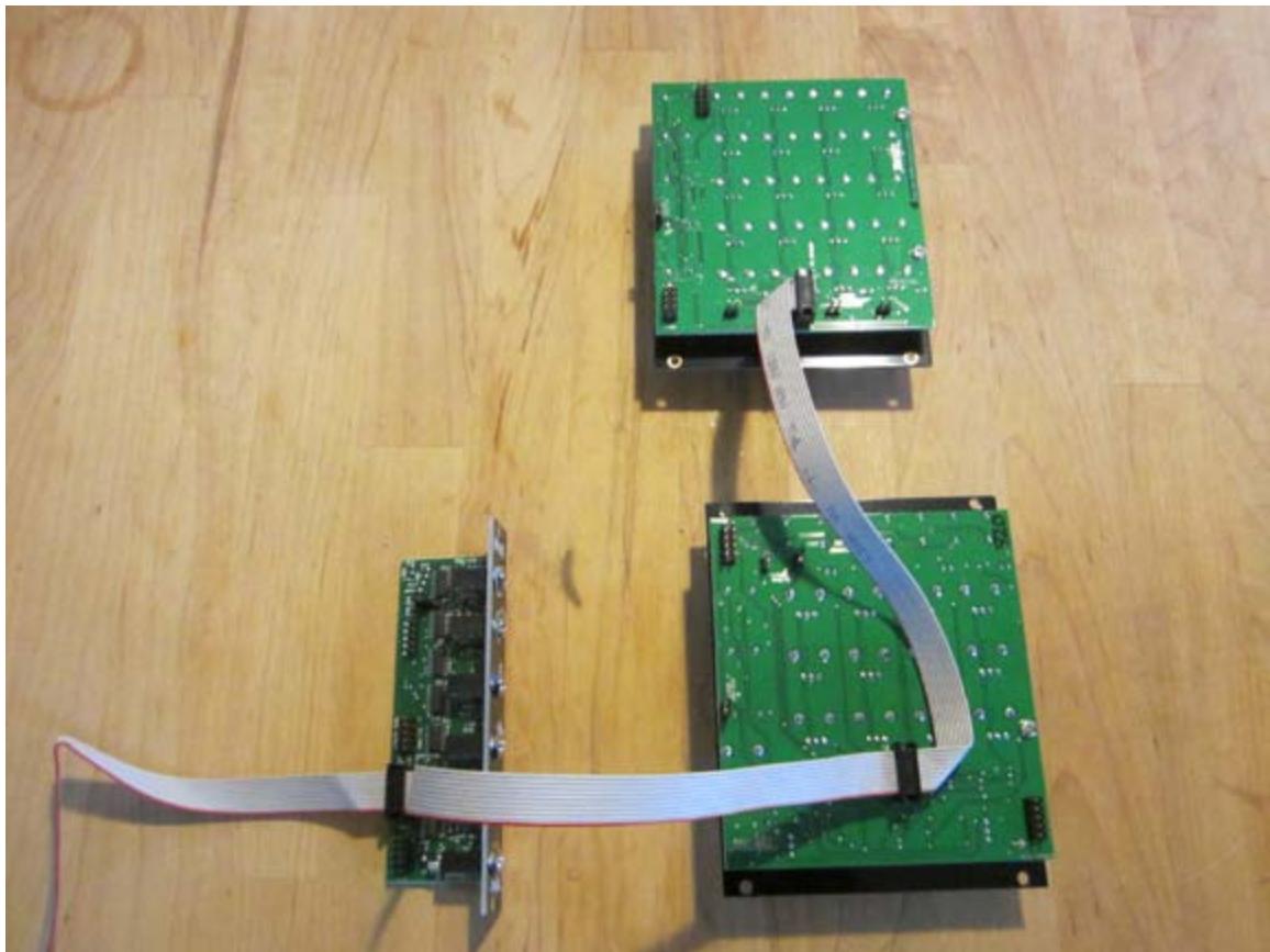
Connect one of the remaining 3 connectors to the 10 pin header on the Pressure Points that is marked "EXPND." You will need to remove all 4 of the small black "jumpers" that are covering the pins of this header before you attach the EXPAND CABLE. Maintain proper orientation of the cable, keeping the Red Stripe DOWN. Connect each Analog Memory to the Pressure Points with which you wish to control it.
Now connect the EXPAND Cable to the 10 pin header on the BRAINS marked "Points 1-4."
Please see the Pressure Points and BRAINS manuals for details on proper jumper settings and connection for Pressure Points/ BRAINS, and follow those instructions.
NOTE: Power Cables removed in photo for clarity.
Connecting 2 Analog Memory to 2 Pressure Points

Connect one of the remaining 3 connectors to the 10 pin header on the Pressure Points that is marked "EXPND." You will need to remove all 4 of the small black "jumpers" that are covering the pins of this header before you attach the EXPAND CABLE. Maintain proper orientation of the cable, keeping the Red Stripe DOWN. Connect each Analog Memory to the Pressure Points with which you wish to control it.
Now connect the EXPAND Cables to the 10 pin headers on the BRAINS marked "Points 1-4" and "Points 5-8." The EXPAND Cable coming of the Pressure Points nearest to the BRAINS is connected to the "Points 1-4."
Using the provided CHAIN cable, connect the two Analog Memory modules at the 10 pin header marked "CHAIN." Maintain proper orientation of the cable, keeping the Red Stripe DOWN at both ends. Analog Memory(s) that are not the that last in the CHAIN will need to have the jumper marked "Close 4 Master" removed.
Please see the Pressure Points and BRAINS manuals for details on proper jumper settings and connection for Pressure Points/ BRAINS, and follow those instructions.
NOTE: Power Cables removed in photo for clarity.
OVERVIEW
The Analog Memory module uses an innovative new data storage technology called "Mechanically Orbited Carbon," to store and recall control voltage values for use within the modular synthesizer system. The MOC RAM technology has the advantage of completely passive non-volatile storage! Power is only used in the generation of the recalled voltage values for use within the modular synthesizer system.
Each Analog Memory module stores up to 20 control voltage values! The data is stored in 4 columns of 5 values. Each stored value is programmed using its own convenient panel control. These 20 controls (1 control per value stored) include a soft touch knob that is pleasing to grip for programming, and marked with a brightly colored indicator line so that the user may view the entire contents of the Analog Memory all at once, at ANY time, even when power is OFF! Programming and operation could not be simpler!
Random Access? Absolutely. The data is accessed immediately at any time using the "Touched Random Access Memory" or TRAM technology packaged within the Pressure Points control module. Simply touch the Touch Plate associated column of values you wish to recall and those voltages will appear. Additionally the Analog Memory is compatible with the BRAINS module for sequential memory access.
Non-volatile storage? Absolutely. Even while powered down, the Analog Memory will retain its entire contents for millions and millions of hours! Care must be taken to avoid physical disturbance of the stored values, so store your Analog Memory in an enclosed and shock resistant case if the data is critical!
Each Analog Memory requires connection to a Pressure Points module for retrieval of stored data. 2 or more (3 is maximum number that has been tested) Analog Memory modules may be connected to a single Pressure Points module. The Analog Memory will also function perfectly within the Pressure Points/ BRAINS system.
Multiple Analog Memory modules may be chained or stacked to create larger data storage systems. Cables are included with each module allowing for complete installation of a data bussing system of up to 4 Analog Memory, 2 Pressure Points and 2 BRAINS. Reasonably priced custom cable assemblies are available for building larger data storage systems. Contact Make Noise for more information.
This module is 20HP and consumes 20mA worth of current.

- Potentiometers for programming Voltage Values.
- Voltage OUTPUTS. Topmost output 0V-8V all others 0V 5.5V These outputs are buffered so that they may drive multiple destinations with out loading affects (dropping).
- Selected Column Indicators. 1 of these 4 LEDs will light to indicate active column.
The Analog Memory must be used with Pressure Points or a Pressure Points/ BRAINS system. using the Analog Memory in a patch is simple. Patch any of the Voltage OUTPUTS to just about any number of CV INPUTS in your system. Set the attenuator (if any) associated with the CV input, to at least 10% so that you may add the voltage from the Analog Memory to the other voltages being used to control the associated parameter. Starting with column 1, program the desired voltage using the associated potentiometer on the Analog Memory. Select the next column and do the same, until all columns have been programmed.


Brand : Make Noise
Model : Analog Memory
Category : Electronic musical instrument