MATHS Classic - Electronic musical instrument Make Noise - Free user manual and instructions
Find the device manual for free MATHS Classic Make Noise in PDF.
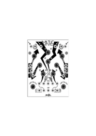


| Product Type | Analog Electronic Musical Instrument |
| Brand | Make Noise |
| Model | MATHS Classic |
| Category | Modular Synthesizer Module |
| Module Format | Eurorack (standard 3U) |
| Panel Width | 20 HP (approx. 101.6 mm) |
| Power Requirement | +/-12V DC regulated |
| Current Draw | 60 mA on both +12V and -12V rails |
| Power Connector | 16-pin Eurorack power header |
| Number of Channels | 4 |
| Channels 1 & 4 Functions | Envelope generator, LFO, slew limiter, function generator |
| Channels 2 & 3 Functions | Attenuator, inverter, DC offset generator |
| Inputs | Signal In (4), Trigger In (2), Rise/Fall/Both Control In (6) |
| Outputs | Signal Out (4), Buffered Multiple Out (2), OR Bus Out, SUM Bus Out |
| Output Voltage Range | 0V to +10V typical |
| Response Curve Control | Logarithmic to Exponential, continuously variable |
| Analog Logic | OR bus and SUM bus |
| Warranty | 2 years limited warranty |
| Documentation | Free user manual (8 pages, English) |
Frequently Asked Questions - MATHS Classic Make Noise
User questions about MATHS Classic Make Noise
0 question about this device. Answer the ones you know or ask your own.
Ask a new question about this device
Download the instructions for your Electronic musical instrument in PDF format for free! Find your manual MATHS Classic - Make Noise and take your electronic device back in hand. On this page are published all the documents necessary for the use of your device. MATHS Classic by Make Noise.
USER MANUAL MATHS Classic Make Noise

Limited WARRANTY:
Make Noise warrants this product to be free of defects in materials Or Construction for a period of two Years from the date of manufacture.
Malfunction resulting from wrong power supply voltages, backwards power cable connection, abuse of the product or any other causes determined by Make Noise to be the fault of the user, are not covered by this warranty, and normal service rates will apply.
During the warranty period, any defective products will be repaired or replaced, at the option of Make Noise, on a return-to-Make Noise basis, With the customer paying the transit cost to Make Noise. Please contact Make Noise for Return To Manufacturer Authorization.
Make Noise implies and accepts no responsibility for harm to person or apparatus caused through operation of this product.
Please contact tony@makenoisemusic.com with any questions, needs & comments... otherwise go MAKE NOISE.
http://www.makenoisemusic.com
Ever since completing the QMMG design, I have felt that it needed a good buddy. A patch pal! Say hello to QMMG's best friend, MATHS.
MATHS builds on the tradition set into motion in the 1960's by Don Buchla when he adapted the circuits found within analog computers common to engineering labs, for musical purposes.
Buchla's "Algebraic Processor, Model 257" changed the way music synthesizers utilized control voltages.
MATHS, a mash-up of the Buchla 281, Buchla 257 & Serge DUSG, continues this great tradition of sculpting the control signals we use to sculpt our sound signals.
Extra special thanx go out to Kelly Kelbel, Richard Devine &
Aaron Abrams for support in the development of MATHS.
Installation:
The Make Noise MATHS is an analog electronic
signal processor/ generator requiring 60mA of +/-12V regulated power and
properly formatted distribution receptacle to operate. It is designed to be used within the euro format modular synthesizer system.
Go to http://www.doepfer.de/a100_man/a100t_e.htm
for the details of this format.
To install, find 20HP of space in your euro-rack synthesizer system,
plug the 16pin power cable into the euro-rack style power distribution board, minding the polarity so that the RED stripe on the cable is oriented to the NEGATIVE12 volt supply line. This is USUALLY at the bottom.
Please refer to your case manufacturers' specifications
for location of the negative supply.
Getting to know MATHS
Like its pal the QMMG, MATHS is laid out top to bottom, and with symmetrical features where the functionality flows from the outside inward. The signal INputs are at the top, followed by the majority of panel controls and Control Signal INputs at the center and at the bottom of the module, the signal OUTputs.
Channels 1 and 4 are identical, each being able to scale, invert or integrate an incoming signal. With no signal applied, these channels may be made to generate a variety of linear, logarithmic, or exponential functions upon the reception of a trigger, or continuously when the CYCLE switch is engaged. The Cycle switch also contains a LED which indicates the activity on the associated channel. One small difference between CH. 1 and 4 is in their respective Pulse outputs; CH.1 having End of Rise and CH. 4 having End of Cycle. This was done to facilitate the creation of complex functions utilizing both CH. 1 and 4.
Channels 2 and 3 are identical, each being able to scale, amplify and invert an incoming signal. With no external signal applied, these channels will generate DC offsets.
All 4 channels are normalized to a SUM and OR bus via their respective OUTputs, so that addition, subtraction and analog logic OR manipulations may be achieved. Inserting a plug to these sockets will remove the associated signal from the SUM and OR bus. Channels 1 and 4 have additional outputs, which are NOT normalized to the SUM and OR bus. Both of these outputs are buffered multiples of their associated main output. By taking your output from this socket, the signal will still be applied to the SUM and OR bus.
Tips & Tricks
-Longer cycles will be achieved with more Logarithmic response curves. The fastest, sharpest functions will be achieved with extreme exponential response curves.
-Adjustment to the response curve will affect Rise and Fall Times.
-To achieve longer or shorter Rise and Fall Times then available from Panel Controls, apply a voltage offset to the Control Signal Inputs of the associated channel.
-Voltage offsets may be generated by CH. 2 or 3.
-When utilizing the SUM and OR OUTputs, set any unused CH. 2 or 3 to NOON or insert a dummy patch cable to Signal Input of associated channel to avoid unwanted offsets.
-If it is desired that a signal processed or generated by CH. 1, 4 is both on the SUM and OR busses AND available as a solo OUTput, utilize the Single OUT Multiple, as it is NOT normalized to the SUM and OR Busses.
-OR function will not respond to or generate negative voltages.
Patch Ideas
Voltage Controlled Transient Generator (Attack/ Decay EG)
A pulse or gate applied to the Trigger IN of CH. 1 or 4 will start the transient function which rises from 0V to 10V at a rate determined by the Rise parameter and then Falls from 10V to 0V at a rate determined by the Fall parameter. This function is re-trigger-able during the Falling portion. Rise and Fall are independently voltage controllable, with variable response from Log thru Linear to Exponential, as set by the Vari-Response panel Control. The resulting function may be further processed with attenuation and/or inversion by the Scale/ Inversion Panel Control.
Voltage Controlled Sustained Function Generator (A/S/R EG)
A gate applied to the Signal IN of CH. 1 or 4 will start the function which rises from 0V to the level of the applied Gate, at a rate determined by the Rise parameter, Sustains at that level until the Gate signal ends, and then Falls from that level to 0V at a rate determined by the Fall parameter. Rise and Fall are independently voltage controllable, with variable response as set by the Vari-Response panel Control. The resulting function may be further processed with attenuation and/or inversion by the Scale/ Inversion Panel Control.
Typical Voltage Controlled Triangle Function
Set CH. 1 (or 4) to self Cycle. Set Rise and Fall Panel Control to NOON. Apply desired modulation to CH. 3 Signal Input. Set CH. 2 Scale/ Inversion Panel Control to NOON. Apply Voltage Offset and modulation as SUMmed, by patching SUM OUT to Both Control Input. CH. 2 Scale/ Inversion will set Frequency. OUTput is taken from Signal OUT of associated channel. Setting Rise and Fall parameters further CW will provide longer cycles. Setting these parameters further CCW will provide short cycles, up to audio rate. The resulting function may be further processed with attenuation and/or inversion by the Scale/ Inversion Panel Control.
Typical Voltage Controlled Ramp Function
As above, only the Rise parameter is set FULL CCW, Fall parameter is set to at least NOON.
Typical Voltage Controlled Pulse
Same as above, only the OUTput is taken from EOC or EOR. CH. 1, Rise parameter will more effectively adjust frequency, and CH. 1 Fall parameter will adjust pulse width. With CH. 4, the opposite is true where Rise adjust more effectively Width and Fall adjust frequency. In both channels all adjustment to Rise and Fall parameters will affect frequency.
Voltage Controlled ADSR (East Coast Envelope done West Coast style)
Apply Gate signal to CH.1 Signal In. Set CH. 1 Scale/ Inversion Panel Control to less then Full CW. Patch CH. 1 End of Rise to CH. 4 Trigger IN. Set CH. 4 Scale Inversion Panel Control to Full CW. Take OUTput from OR bus OUT, being sure that CH. 2,3 are set to NOON if not in use. In this patch CH. 1 and 4 Rise will control the Attack Time. For typical ADSR adjust these parameters to be similar (Setting CH. 1 Rise to be longer then CH. 4 will or vice-versa, will produce two attack stages). CH. 4 Fall parameter will adjust the Decay stage of the envelope. CH. 1 Scale/ Inversion Panel Control will set the Sustain level, which MUST be lower then that same parameter on CH. 4. Finally CH. 1 Fall will set the Release Time.
Voltage Comparator/ Gate Extraction w/ variable width
Apply signal to be compared to CH. 2 Signal IN. Patch CH. 2 OUT to CH. 1 Signal IN. Set CH. 1 Rise and Fall to full CCW. Take extracted Gate from EOR. CH. 2 Scale/ Inversion acts as the Threshold setting, applicable values being between NOON and Full CW. Values closer to NOON will be HIGHER thresholds. Setting the Rise times CW, you will be able to Delay the derived gate. Setting Fall times CW you will vary the width of the derived Gate. Use CH. 4 for Envelope Follower, and CH. 2 & 1 for Gate extraction, and you have a very powerful patch for external signal processing.
Gate Controlled CYCLE
Apply Gate to CH. 2, set CH. 2 Scale control to 3 o' clock. Patch CH. 1 EoR to CH. 3 and set Scale control to Full CW. Using mult or stack-cable, patch OR OUT to both CH. 1 & 4 Trigger IN. Take output form CH. 4 Signal OUT multiple (bottom row). Patch dumby cable to CH. 1 Signal OUT (top row), or use this signal else where in the patch. CH. 1 Rise controls the trigger delay time. CH. 4 Fall must always be shorter then CH. 1 Fall. The Response knob acts as a fine tune for timing lengths as well as setting the shape. Pathc will CYCLE so long as Gate is HIGH. Special thanx to Don Kim for this patch idea.
Toggled Delayed CYCLING
This is the patch that from which my idea for the above Gate Controlled CYCLE patch originated. Set up the above patch but take the SUM OUT and mult to both CH. 1 & 4 Trigger IN. instead of the OR OUT. Gate must be longer in duration then the CYCLE time as set by Rise and Fall of CH. 1 and CH. 4. This patch works great with Pressure Points, utilizing on of Gate OUTs on that module. Special thanx to Don Kim for this very unique patch idea.
Envelope Follower
Apply Signal to be followed to Signal IN CH. 1 or 4. Set Rise to NOON. Set and or modulate FALL Time to achieve different responses. Take output from associated channel Signal OUT for positive and negative Peak Detection. Take output from OR buss OUT to achieve more typical Positive ONLY Envelope Follower function. If gain is needed, pathc signal to CH. 2 or 3, and set Scale/ Inversion to full CW. Take output from associated channel OUT.
I/O and Panel Controls Explained
Signal IN (CH. 1,2,3,4): Direct Coupled input to associated circuit. Channels 2 and 3 are normalized to a +5V reference for generation of voltage offsets.
Trigger IN (CH. 1,4): Gate or Pulse applied to this input will trigger the associated circuit regardless of activity at the Signal IN. The result being a 0V to 10V voltage function, aka Envelope, whose characteristics are defined by the Rise, Fall, Vari-Response and Scale/Inversion parameters.
Activity/ Cycle Switch (CH. 1,4): This LED indicates activity within the associated circuit. It also leads a double life as a push button which coaxes the circuit to self cycle, thus generating a repeating voltage function, aka LFO.
Rise Panel Control (CH. 1,4): Sets the time it takes for the voltage function to ramp up. CW rotation increases Rise Time.
Fall Panel Control (CH. 1,4): Sets the time it takes for the voltage function to ramp down. CW rotation increases Fall Time.
Rise Control IN (CH. 1,4): Bi-Polar Linear control signal input for Rise parameter. Positive Control signals increase Rise Time. Negative control signals decrease Rise Time.
Fall Control IN (CH. 1,4): Bi-Polar Linear control signal input for Fall parameter. Positive control signals increase Fall Time. Negative control signals decrease Fall Time.
Both Control IN (CH. 1,4): Bi-Polar Exponential control signal input for entire Function. Positive control signals decrease Total Time. Negative control signals increase Total Time.
Scaling/ Inversion Panel Control (CH. 1,2,3,4): provides for scaling, attenuation and inversion of the signal applied to the associated channel. When this control is set to NOON, there will be zero signal. At full CW there will be maximum signal. At full CCW there will be maximum Inverted signal. Channels 2 and 3 also offer a small amount of Gain.
Vari-Response Panel Control (CH. 1,4): sets the response curve of the voltage function for the associated circuit. Response is continuously variable from Logarithmic through Linear to Exponential.
Signal OUT (CH. 1,2,3,4): the applied signal as processed by the associated MATHS channel. All four of these sockets are normalized to the SUM and OR busses. Inserting a patch cable will remove the associated signal from the SUM and OR busses. All of these outputs are buffered and capable of accurately driving a 4 way multiple.
Signal OUT Multiple (CH. 1,4): buffered multiple of the Signal OUT for the associated circuit. This socket is NOT normalized to the SUM and OR busses and therefore, inserting a patch cable to this socket will not remove the associated signal from the Sum and OR busses.
OR Bus OUT: Result of the Analog Logic OR function.
SUM Bus OUT: Sum of the applied voltages.

More Patch Ideas
281 "Quadrature Mode" (West Coast Swirly Bird)
In this patch, CH. 1,4 work in tandem to provide functions shifted by ninety degrees. With both Cycle Switches UN-ENGAGED, Patch End of Rise (CH. 1) to Trigger IN CH. 4. Patch End of Cycle (CH. 4) to Trigger IN CH. 1. If both CH.1 and 4 do not begin cycling, engage CH. 1 Cycle Briefly. With both channels cycling, apply their respective Signal OUTputs to two different modulation destinations, for example two channels of the QMMG.
VC LAG/ Slew Processor
A signal applied to the Signal IN, is slewed according to the RISE and FALL parameters. Variable response from Log thru Linear to Exponential, is as set by the Vari-Response panel Control. The resulting function may be further processed with attenuation and/or inversion by the Scale/ Inversion Panel Control.
East Coast Portamento
Set CH. 1 Rise and Fall to NOON, Vari-Response to Full CCW. Patch CH. 1 Signal OUT (top row) to CH. 2 Signal IN, set CH. 2 Scale to Full CCW, patch SUM OUT to CH. 1 BOTH Control IN. Set CH. 3 Scale panel control to NOON. Patch CV to be slewed into an Obie like portamento to CH. 1 Signal IN. Take output from CH. 1 Signal OUT, bottom row. In this patch CH. 2 Scale panel control will set the extremeness of the LOG response, Full CCW being the most extreme. CH. 3 Scale panel control will set rate of the portamento, CW being faster and CCW being slower. If you wanted to get even fancier, you could patch the mod-wheel from your CV Keyboard (or Press CV from Pressure Points) to CH. 4 Signal IN, and use mod-wheel or Pressure to influence and control the portamento rate (just be sure nothing is patched to CH. 4 OUT, top row, so that the signal is sent to the SUM BUSS, and if you use CH. 4 for something else, be sure to utilize the TOP Row output to break the normalization.
Arcade Trill
Set CH. 4 Rise and Fall to NOON, scale/ Inversion to 9 o'clock. Patch EOC to CH. 1 Trigger IN. Patch CH. 4 Signal OUT to CH. 1 Both IN. Set CH. 1 Rise to NOON, Fall to full CCW. Engage CH. 4 Cycle switch. Apply Signal OUT CH. 1 to modulation destination. CH. 4 Scale/ Inversion, Rise and Vari-Response Parameters vary trill.
Chaotic Trill (requires QMMG or other Direct Coupled LP filter)
Begin with Arcade Trill patch. Apply MATHS CH. 1 Signal OUT to MATHS CH. 2, setting Scale/Inversion to 1 o'clock. Apply CH. 2 Signal OUT QMMG CH. 1 Control IN. Patch EOR to to QMMG CH. 1 Signal IN, set to LP mode, no feedback, starting with Offset at full CCW. Apply QMMG CH. 1 Signal OUTput to MATHS CH. 4 Both IN. QMMG Offset and MATHS CH. 2 Scale/ Inversion panel controls will be of interest.
Independent Contours
By processing the Signal OUT of CH. 1, 4 with CH. 2,3 and feeding that signal back into CH. 1, 4 at RISE or FALL Control IN, independent control of the corresponding slope is achieved. Best to have the Response panel control set to NOON.
Bouncing Ball (requires QMMG or Dual VCA)
Apply same trigger or Gate to CH. 1 CH. 4 Trigger IN. Set Rise to full CCW and Fall to 3 o'clock, Scale/ Inversion to full CW. Patch CH. 1 Signal OUT to CH. 2 Signal IN. Set Ch. 2 Scale/ Inversion to 10 o'clock. Apply CH. 2 signal out to CH. 4 Both IN. Set CH. 4 Rise full CCW, Fall set to NOON, Scale/ Inversion to Full CW and engage Cycle Switch. Patch CH. 4 Signal out to QMMG CH. 1 Signal IN. Patch MATHS CH. 1 Signal OUT Multiple to QMMG CH. 1 Control Signal IN. Set QMMG CH. 1 Offset to full CCW, Feedback to 9 o'clock, set mode to VCA. Apply Signal to be bounced to QMMG CH. 2 Signal IN where Offset is set to full CCW and feedback is set to 9 o'clock, mode is Both. Patch QMMG CH. 1 Signal OUT to QMMG CH. 2 Control Signal IN. Monitor QMMG CH. 2 Signal OUT. MATHS Vari-Response panel controls will act as a sort of Gravity parameter, where both should be set similar and more Logarithmic response will be less gravity. MATHS CH. 1 Fall parameter is a sort of Restitution control. Increasing Fall parameter means the ball will bounce more times. Shorter Falls times will bring fewer bounces. Setting Fall to before NOON will result in no bouncing. High Gravity settings combined with fewer bounces yields a reverb like sound effect with QMMG.
MATHS is FUN
FLIP-FLOP (1-Bit Memory)
In this patch CH. 1 Trigger IN acts as the “Set” input, and CH. 1 BOTH Contrl IN acts as the “Reset” input. Apply Reset signal to CH. 1 BOTH Control IN. Apply Gate or logic signal to CH. 1 Trigger IN. Set Rise to Full CCW, Fall to Full CW, Vari-Response to Linear. Take “Q” output from EOC. Patch EOC to CH. 4 Signal to achieve “NOT Q” at the EOC OUT. This patch has a memory limit of about 3 minutes, after which it forgets the one thing you told it to remember.
Voltage Controlled Pulse Delay Processor
Apply Trigger or Gate to Trigger IN if CH. 1. Take output from End Of Rise. RISE parameter will set the delay and Fall parameter will adjust width of the resulting delayed pulse.
Voltage Controlled Clock Divider
Clock signal applied to Trigger IN CH. 1 or 4 is processed by a divisor as set by Rise parameter. Increasing Rise sets divisor higher, resulting in larger divisions. Fall time will adjust the width of the resulting clock. If the Width is adjusted to be greater the the total time of the division the output will remain “high.” Take output from EOR or EOC.
Logic Invertor
Apply logic gate to CH. 4 Signal IN. Take output from CH. 4 EOC.
Half Wave Rectification
Apply bi-polar signal to CH. 1, 2, 3, 4 IN. Take output from OR out. Mind the normalizations to the OR buss.
Full Wave Rectification
Mult signal to be rectified to both CH. 2 and 3 IN. CH 2 Scaling/ Inversion set to Full CW, CH. 3 Scaling/ Inversion set to Full CCW. Take output from OR Out. Vary the Scaling.
ADD, Subtract Control Signals
Apply signals to be added/ subtracted to any combination of Signal IN CH. 1,2,3,4 (when using CH. 1,4 Rise and Fall must be set to full CCW, and Cycle switch not engaged). Set Scale/ Inversion panel controls for channels to be added, to full CW. Set Scale/ Inversion panel controls for channels to be subtracted to full CCW. Take output from SUM OUT.
Peak Detector
Patch signal to be detected to CH. 1 Signal IN. Set Rise and Fall to 3 'o' Clock. Take output from Signal OUT. Gate out from EOR OUT.
Voltage Mirror
Apply Control Signal to be mirrored to CH. 2 Signal IN. Set CH. 2 Scale/ Inversion panel control to Full CCW. With nothing inserted at CH. 3 Signal IN (so as to generate an offset), set CH. 3 Scale/ Inversion panel control to full CW. Take output from SUM OUT. This patch will also work as a Logic Invertor.
Multiplication
Apply positive going Control Signal to be multiplied to CH1 or 4 Signal IN. Set Rise to full CW, Fall to Full CCW. Apply positive going, multiplier Control Signal to BOTH Control IN. Take output from corresponding Signal OUT.


- INSTALLATION
- GETTING TO KNOW MATHS
- TIPS & TRICKS
- PATCH IDEAS
- VOLTAGE CONTROLLED TRANSIENT GENERATOR (ATTACK/ DECAY EG)
- VOLTAGE CONTROLLED SUSTAINED FUNCTION GENERATOR (A/S/R EG)
- TYPICAL VOLTAGE CONTROLLED TRIANGLE FUNCTION
- TYPICAL VOLTAGE CONTROLLED RAMP FUNCTION
- TYPICAL VOLTAGE CONTROLLED PULSE
- VOLTAGE CONTROLLED ADSR (EAST COAST ENVELOPE DONE WEST COAST STYLE)
- VOLTAGE COMPARATOR/ GATE EXTRACTION W/ VARIABLE WIDTH
- GATE CONTROLLED CYCLE
- TOGGLED DELAYED CYCLING
- ENVELOPE FOLLOWER
- I/O AND PANEL CONTROLS EXPLAINED
- MORE PATCH IDEAS
- QUADRATURE MODE" (WEST COAST SWIRLY BIRD)
- VC LAG/ SLEW PROCESSOR
- EAST COAST PORTAMENTO
- ARCADE TRILL
- CHAOTIC TRILL (REQUIRES QMMG OR OTHER DIRECT COUPLED LP FILTER)
- INDEPENDENT CONTOURS
- BOUNCING BALL (REQUIRES QMMG OR DUAL VCA)
- MATHS IS FUN
- FLIP-FLOP (1-BIT MEMORY)
- VOLTAGE CONTROLLED PULSE DELAY PROCESSOR
- VOLTAGE CONTROLLED CLOCK DIVIDER
- LOGIC INVERTOR
- HALF WAVE RECTIFICATION
- FULL WAVE RECTIFICATION
- ADD, SUBTRACT CONTROL SIGNALS
- PEAK DETECTOR
- VOLTAGE MIRROR
- MULTIPLICATION
Brand : Make Noise
Model : MATHS Classic
Category : Electronic musical instrument