RxMx - Modular audio module Make Noise - Free user manual and instructions
Find the device manual for free RxMx Make Noise in PDF.


User questions about RxMx Make Noise
0 question about this device. Answer the ones you know or ask your own.
Ask a new question about this device
Download the instructions for your Modular audio module in PDF format for free! Find your manual RxMx - Make Noise and take your electronic device back in hand. On this page are published all the documents necessary for the use of your device. RxMx by Make Noise.
USER MANUAL RxMx Make Noise
RXMX


RxMx
Limited Warranty 3
Installation 4
Expansion 5
Overview 6
Perspective 7
Panel Controls 8
Getting Started 10
A Bit More on Channel and Radiate 11
Patch Ideas 12
Make Noise warrants this product to be free of defects in materials or construction for a period of one year from the date of purchase (proof of purchase/invoice required).
Malfunction resulting from wrong power supply voltages, backwards or reversed eurorack bus board cable connection, abuse of the product, removing knobs, changing face plates, or any other causes determined by Make Noise to be the fault of the user are not covered by this warranty, and normal service rates will apply.
During the warranty period, any defective products will be repaired or replaced, at the option of Make Noise, on a return-to-Make Noise basis with the customer paying the transit cost to Make Noise.
Make Noise implies and accepts no responsibility for harm to person or apparatus caused through operation of this product.
Please contact technical@makenoisemusic.com with any questions, Return To Manufacturer Authorization, or any needs & comments.
http://www.makenoisemusic.com

About This Manual:
Written by Tony Rolando
Edited by Walker Farrell
Illustrated by W.Lee Coleman
Special Thanks to:
Grant Richter, founder Wiard Synthesizers
Don Buchla, inventor of the Lowpass Gate
The Surrealists, inventors of Cadavre Exquis
Electrocution hazard!
Always turn the Eurorack case off and unplug the power cord before plugging or un-plugging any Eurorack bus board connection cable.
Do not touch any electrical terminals when attaching any Eurorack bus board cable.
The Make Noise RxMx is an electronic music module requiring 35mA of +12VDC and 30 mA of -12VDC regulated voltages and a properly formatted distribution receptacle to operate. It must be properly installed into a Eurorack format modular synthesizer system case.
Go to http://www.makenoisemusic.com/ for examples of Eurorack Systems and Cases.
To install, find 20HP in your Eurorack synthesizer case, confirm proper installation of included eurorack bus board connector cable on backside of module (see picture below), plug the bus board connector cable into the Eurorack style bus board, minding the polarity so that the RED stripe on the cable is oriented to the NEGATIVE 12 Volt line on both the module and the bus board. On the Make Noise 6U or 3U Busboard, the negative 12 Volt line is indicated by the white stripe.

Please refer to your case manufacturers' specifications for location of the negative supply.
The Outputs of the Make Noise FXDf can be normalled to the 6 Channels of the RxMx by using the included 10-pin chain connector cable and connected as indicated below.

Alternatively, you could connect the DPO's waveforms to the 6 Channels of the RxMx by using the included 10-pin chain connector cable and connected as indicated below.

The RxMx is a Vactrol-based 6-Input, 3-Output, Macro-Low Pass Gate and Signal Crossfader. The concept is based on Grant Richter's circuit idea for applying "cadavre exquis" (a.k.a. exquisite corpse, a technique of serial blind composition) to modular synthesis. When modulating the RxMx with a Wogglebug, one will achieve modular "cadavre exquis." When patch programming the RxMx with a sequencer such as the Pressure Points/ BRAINS or René, modular "mélanger automatique" (automatic re-mixing) can be achieved. Because it uses Low Pass Gates for Level control and crossfading, the RxMx excels at smooth dynamic blending and percussive animation of related or unrelated signals.
The Level and Strike parameters are similar to those of the Make Noise Optimix. If you're unfamiliar, Level controls the amplitude and frequency content simultaneously. Strike can be used to trigger Channel(s) of the LPG (Low Pass Gate) circuit by "plucking" or "pinging" the vactrol, briefly opening the LPG circuit to 100%, thus allowing it to impart its magically-slow response time upon the amplitude of the signal being processed.
The Channel parameter selects which of the 6 Low Pass Gate circuits is driven by the Level and Strike parameters and the Radiate parameter turns on channels adjacent to the one chosen by the Channel parameter. At maximum Radiate settings, it is possible to have all six channels become active simultaneously. Therefore, Radiate allows for Voltage Control of the complexity of the mix, ranging from 1 to 6 active sound sources, with Channel selecting the focal point of the mix.
There is an Expansion Header on the back of the module, allowing for un-patched connection to 6 Waveforms from the DPO (2 of which are not accessible on DPO itself), resulting in gorgeous, waveform scanning. When normalled to a DPO, the Waveform Channel distribution is as follows:
Ch 1: VCO A Saw
Ch 2: VCO A Triangle
Ch 3: VCO A Sine
Ch 4: VCO B Triangle
Ch 5: VCO B Final Output
Ch 6: VCO B Spike
Connecting the RxMx Expansion cable to the DPO does not change any behaviors on the DPO. Any internal connection from DPO to RxMx may be overridden by patching into one of the RxMx Channel Inputs.
Alternatively, you could choose to use the un-patched connection to the 6 bands of the FXDf Fixed Filter module via the Expansion Header, allowing for Voltage-Controlled, percussive spectral animation of a single sound source, such as a loop from the Phonogene. For more information, consult the FXDf Manual.
Connecting the RxMx Expansion cable to the FXDf does not change any behaviors on the FXDf. Any internal connection from FXDf to RxMx may be overridden by patching into one of the RxMx Channel Inputs.
Using the 3 Outputs, the RxMx can have a variety of output configurations. Choose either (1) Six-Channel Output, (3) two-Channel Outputs, or (1) Four-Channel and (2) Two-Channel Outputs for parallel processing patches with up to 3 independent signal processing paths. The Aux A and Aux C inputs are also available for adding two more signals to the mix such as the SUM Outs from the Optimix and modDemix, allowing for larger more complex mixes to be patched.
The RxMx contains 100% analog filters and gain cells designed for musical applications and is not suitable for laboratory use. The RxMx, being a Vactrol-based circuit, never has the speed or tight-tolerances found in many other VCA and VCF circuits.
I would recommend that musicians desiring closely-matched Gain across multiple channels of VCAs look elsewhere! What the RxMx does offer is extremely-low noise with low distortion, in a smooth, natural-sounding circuit.

RxMx Panel Controls
- Out A: 10Vpp (depending upon Level setting and source material), DC coupled output for CH. 1, CH. 2 and Aux A. Normalled to Out B.
- Out B: 10Vpp (depending upon Level setting and source material), DC coupled output for CH. 3, CH. 4 additionally Out A and Out C are Normalled to this output.
- Out C: 10Vpp (depending upon Level setting and source material), DC coupled output for CH. 5, CH. 6 and Aux C. Normalled to Out B.
- Aux A: Direct coupled signal input to the Out A sum circuit. Capable of accepting audio or control signals. Also allows for the chaining of multiple RxMx, OPTOMIX and modDemix units to create larger mixes. Typical input range of 10Vpp.
- Aux C: Direct coupled signal input to the Out C sum circuit. Capable of accepting audio or control signals. Also allows for the chaining of multiple RxMx, OPTOMIX and modDemix units to create larger mixes. Typical input range of 10Vpp.
- Inputs for CH. 1, CH. 2, CH. 3, CH. 4, CH. 5 and CH. 6: Direct coupled signal input capable of accepting audio or control signals. Normalized to Expansion header for use with DPO or FXDf. Typical input range of 10Vpp.
- Input Attenuators for CH. 1, CH. 2, CH. 3, CH. 4, CH. 5 and CH. 6: Sets input Level for associated Channel input. This attenuator is before the LPG circuit.
- Channel Drive Indicators 1, 2, 3, 4, 5, 6: LEDs to indicate which of the 6 LPG circuits are currently selected and being driven by the Level and Strike parameters.
RxMx Panel Controls (Cont'd)
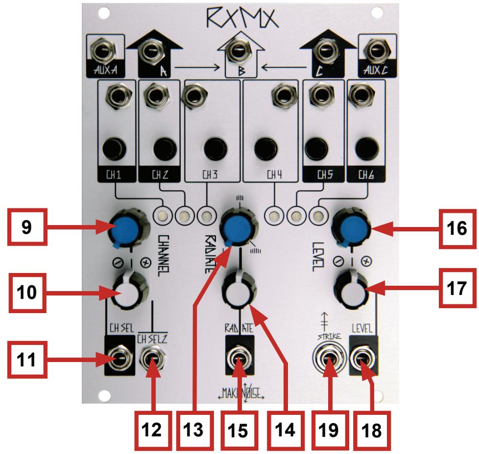
- Channel Panel Control: Uni-polar control for selecting which of the 6 Low Pass Gate circuits is driven by the Level and Strike parameters. Possible selections are 0 (no Channel), 1, 2, 3, 4, 5 and 6.
- Channel Select CV Attenuverter 1: Bi-Polar attenuator for Channel Select CV Input 1.
- Channel Select CV Input 1: Control signal input for Channel Selection. Associated with Channel Select CV Attenuator 1. Range 0V to 5V.
- Channel Select CV Input 2: Control signal input for Channel Selection. No attenuation, unity gain input. Range 0V to 5V.
- Radiate Panel Control: Uni-polar control that turns on channels adjacent to the one set by Channel parameter.
- Radiate CV Attenuator: Uni-Polar attenuator for Radiate CV Input.
- Radiate CV Input: Control signal input for Radiate. Radiate CV Attenuator. Range 0V to 10V.
- Level Panel Control: Uni-polar control for driving lowpass-gate circuit selected by Channel parameter, which determines amplitude and frequency content of signal simultaneously.
- Level CV Attenuverter: Bi-Polar attenuator for Level CV Input.
- Level CV Input: Control signal input for Level. Associated with Level CV Attenuator. Range 0V to 8V.
- Strike Input: Gate input for striking, pinging or plucking the Lowpass Gate. Expects 8V Gate signal.
The RxMx contains 6 Low Pass Gate circuits. The LPG is a specialized type of synthesizer circuit developed by Don Buchla, where the amplitude of the signal is not only frequency dependent, but also under Voltage Control. It is in essence, a Voltage-Controlled Filter and Amplifier, a VCF A. Traditionally, the Lowpass Gate has had a very mild filter slope of 6db/Octave. This mild filtering, combined with the use of an optoisolator-based gain cell that turns off, allows for simultaneous control of both the amplitude and frequency domains.
Level and STRIKE
As the Level parameter becomes more positive, the amplitude of the processed signal increases with the lower frequencies being more quickly amplified than high frequencies. As the Level parameter become less positive, the amplitude decreases with the high frequencies being attenuated much sooner than the lower frequencies. The net effect is fast, transient modulation of the signal Level the low frequencies will be more pronounced-- lurking in the spectrum, as the high frequencies are quickly diminished.
Manual manipulation of the controls does not well display this phenomenon. A fast/short envelope CV of around +8V will provide beautiful example of the RxMx's ability to produce acoustic like attack & decay transients. The processed signal rings, not unlike a struck drum, piano string, or xylophone bar. The Strike Input allows for ease in programming percussively-animated sounds, taking advantage of these characteristics of the Low Pass Gate circuit. A Gate patched to the Strike Input initiates a fast/short control signal to briefly open the LPG to 100% for a moment before closing with a very organic decay.
The RxMx is called a macro-lowpass-gate because it has 6 LPG circuits that share a single set of LPG controls. These shared controls are the Level and Strike parameters discussed in the paragraph above. The Level and Strike controls may be applied to any of the 6 LPG circuits in CH. 1 through 6. The Channel and Radiate parameters are used to determine to which of the 6 Channel s the Level and Strike parameters are applied.
Channel and Radiate
With Channel and Radiate Full CCW and no modulation (nothing patch to CH SEL CV Input 1 or 2, or Radiate CV Input), “CH. Zero” or no Channel is selected and no radiation is applied to turn on adjacent channels. Therefore, none of the 6 Channel Drive Indicators will be lit-- even if Level and/or Strike parameters are modulated, you will get no signal(s) at any of the 3 outputs unless you have something patched to Aux A and/ or Aux C (this is because the Aux Ins are not processed by the Channel, Radiate, Level and Strike parameters).
Setting Channel to around 8:00 selects CH. 1 and if Level and/or Strike is modulated (or Level Panel Control is manually set to greater then 8:00), the CH. 1 Drive Indicator LED fades on as the Level parameter is increased. A signal present at CH. 1 Input appears at Out A or Out B (depending upon which Out is patched), at a Level based on the CH. 1 Attenuator and the Level and Strike parameters. If the Channel parameter is increased, CH. 2 through 6 is selected and the associated Drive Indicator LED turns on and the signal patched to selected Channel appears at the associated Output based on the setting of the associated Channel Attenuator and Level and Strike parameters. Notice that with Radiate Full CCW and no modulation applied to Radiate CV in, only one Channel will be active at a time.
Because the Radiate parameter turns on adjacent channels, it possible to achieve similar results using the Radiate controls. With Channel set Full CCW and no Channel modulation (nothing patch to CH SELCV Input 1 or 2) CH. 0 is selected. Although no physical CH. 0 exists in the RxMx, it is still a possible Channel selection. Therefore, increasing the Radiate parameter value will turn on channels adjacent to CH. 0, beginning with CH. 1. If Level and/or Strike is modulated (or Level Panel Control is manually set to greater than 8:00), the CH. 1 Drive Indicator lights and the signal patched or normalled to CH. 1 Input appears at Out A or Out B (depending upon which Out is patched), at a Level based on the CH. 1 Attenuator and the Level and Strike parameters.
If the Radiate parameter is increased, CH. 2 will also turn on. Increasing the Radiate parameter gradually turns on adjacent channels-- all the way up to CH. 4, with the associated Drive Indicator LEDs lighting as the signals patched to the selected channels appears at the associated Outs, based on the settings of the their associated Channel Attenuators and the Level and Strike parameters.
As Radiate turns on adjacent channels, if the Channel parameter is set to 12:00 or 50% (CH. 3 or 4 selected), it is possible to turn on all 6 channels at once by turning Radiate fully clockwise. Additionally, it is possible to crossfade from one group of channels to another by setting Radiate to determine the number of channels grouped and using Channel to move through all possible groupings.
This may sound more confusing than it really is... thankfully, it is all very easy to grasp visually by simply experimenting with the Channel, Radiate and Level controls and watching the 6 Channel Drive Indicator LEDs. By manually adjusting the panel controls, it is possible to gain a deeper understanding of the possibilities the RxMx offers in terms of scanning, blending, and mixing multiple signal sources.
Once you grasp the behavior of the Channel, Radiate and Level parameters, patch six sound sources to the six Channel Inputs. These could be related or unrelated signals. For example, you could patch two different sequences using the Pressure Points/ BRAINS and two STO VCOs (or VCO A and B of the DPO) and then patch the different waveform outputs to the 6 Inputs of the RxMx. Set all Channel Input Attenuatorsto Full CW. Monitor using Out B in order to hear all 6 Channels, as well as both Aux Ins, from a single output (this is due to the normalizations of Out A and C to Out B). Feel free to manipulate and experiment by manually setting Channel, Radiate and Level and listening to how the final mix (from Out B) varies with these changes.
Click and Pop Beat Box patch (requires FXDf normalled to RxMx)
Record a Loop into Phonogene or Morphagene. Patch the Output to FXDf 12db Input. Set Phonogene Gene Size to 12:00 and later adjust to taste. Patch master clock or division of master clock to Gene Shift. Set Phonogene Vari-Speed to taste. Generate Cycling Function using either MATHS or FUNCTION module. Set Rise to about 1:00 and Fall to about 12:00, and later adjust for variation. Patch non-inverted Output from MATHS/FUNCTION Channel used to the RxMx Channel Select CV Input 1. Set CHANNEL panel control to Full CCW. Set CH SEL Attenuator to 5:00. Set RADIATE to Full CCW. Patch master clock or gate sequence to RxMx Strike In and Set Level to Full CCW. Monitor RxMx Out B. Now adjusting Rise and Fall times will generate variations. Adjusting Gene Size and Vari-Speed will vary the timbre. Use RxMx CH. Input Attenuators to adjust the mix.

Cadavre Exquis
-Patch any six audio sources to the six inputs of the RxMx. Set Level full CW, Radiate full CCW, Channel Full CCW.
-Patch Wogglebug Stepped Random to Channel CV Input 1, adjusting input attenuator to allow random selection of all six channels. Adjust Wogglebug clock to taste.
Mélangeur Automatique
-Same patch as "Cadavre Exquis," but use a non-random stepped voltage source such as René or BRAINS/Pressure Points.

Taxonomy
-Mult a single audio source to channels 1, 3 and 5. Optionally, mult a second source to 2, 4, and 6.
-Patch A, B, and C Outputs to three audio-processing destinations of your choice: ring mod, echo, reverb etc.
-Apply control voltage to Channel CV input to switch rhythmically between different effects processes.
-Increase Radiate to engage multiple effects at once in parallel.
Panopticon
-Patch six sources of your choice to the RxMx signal inputs.
-Engage cycling on Function, and patch Function + Output to Channel CV Input 1.
-Patch Pressure Points Common Gate or BRAINS T-Gate to HANG input on Function, Common Pressure Out to Radiate CV Input. Press a touchplate to focus on a single channel and increase width of selection by pressing harder on the touchplate. Don't let anything escape you.
Encounters
-Clock Wogglebug, BRAINS and René with a single clock, or with different clocks.
-Patch the three Pressure Points Tuned Voltage outputs to Ch 1-3 of RxMx
-René QCV and CV to Ch4 and Ch5 (for best results use a saved location on the Q page to allow the two outputs to be independent)
-Patch Wogglebug Stepped Random Output to Ch6. -Patch RxMx B Output to 1v/Oct Input on a VCO such as the STO. -Mult various versions of the same sequence outputs to Level, Radiate and Channel CV Inputs, or manipulate the Panel Controls manually to mix, match and paint sequences.
Prepared Piano
-Patch RxMx B Output to VCO FM Input. Patch VCO to Optomix Channel Input.
-Patch Tuned Voltage out from 2 chained Pressure Points to VCO 1V/Oct input, and mult to RxMx Channel CV Input.
-Tune Pressure Points channels so that Channel selection goes up from left to right.
-Patch Pressure Points Common Gate to RxMx Strike, and mult to Optomix Strike.
-Patch Pressure Points Common Pressure to RxMx Level CV Input, and Mult to Radiate CV Input.
- Apply six audio sources of arbitrary frequencies and timbres to RxMx Signal inputs. Play the prepared piano. If you do not have two Pressure Points, a Prepared Player Piano can be emulated by substituting a sequencer.




- RXMX
- ABOUT THIS MANUAL
- ELECTROCUTION HAZARD
- CONNECTING THE RXMX EXPANSION CABLE TO THE DPO DOES NOT CHANGE ANY BEHAVIORS ON THE DPO. ANY INTERNAL CONNECTION FROM DPO TO RXMX MAY BE OVERRIDDEN BY PATCHING INTO ONE OF THE RXMX CHANNEL INPUTS
- RXMX PANEL CONTROLS
- RXMX PANEL CONTROLS (CONT'D)
- LEVEL AND STRIKE
- CHANNEL AND RADIATE
- CLICK AND POP BEAT BOX PATCH (REQUIRES FXDF NORMALLED TO RXMX)
- CADAVRE EXQUIS
- MÉLANGEUR AUTOMATIQUE
- TAXONOMY
- PANOPTICON
- ENCOUNTERS
- PREPARED PIANO
Brand : Make Noise
Model : RxMx
Category : Modular audio module