DFC3D - Audio Console AMS Neve - Free user manual and instructions
Find the device manual for free DFC3D AMS Neve in PDF.


| Product Type | Digital Film Console (Audio Console) |
| Brand | AMS Neve |
| Model | DFC3D |
| Category | Audio Console |
| Rack Units | SPS Rack 7U / 13U, Encore Processor Rack 4U, MIOS Rack 4U, Monitor Facilities Rack 3U, AES I/O Unit 2U |
| Dimensional Variations | Modular baskets: 8, 16, and 24 channel sections; overall width calculated from basket sizes and side trims |
| Cable Lengths | CAT6 digital communication up to 80 m; AES/EBU up to 100 m |
| Audio Connectivity | 56-pin Varicon, XLR (balanced), MADI optical/coaxial, AES/EBU |
| Machine Control | 5x Sony 9-pin ports (RS-422), 1x ES/2 synchroniser port (DA15), Services port (DB25) |
| Synchronisation | AES SYNC, Word Clock In/Out, Video reference, Timecode, internal reference |
| Mains Power | Auto voltage sensing; 10A IEC (7U) / 16A IEC (13U); recommended UPS |
| Power Consumption | SPS 13U: 800W, SPS 7U: 600W, Encore: 400W, MIOS: 180W, MON FAC: 90W, AES I/O: 60W |
| Cooling | Fan-cooled racks (Encore, MIOS, AES I/O); ambient below 30°C; free airflow front-to-back |
| Rack Mounting | 19" cabinet, min 700mm depth, support rails for >3U units |
| Weight (approx) | SPS 7U: 51 kg, SPS 13U: 62 kg, Encore: 30 kg, MIOS: 21 kg, MON FAC: 15 kg, AES I/O: 9 kg |
| Static Precautions | Conductive workbench, no synthetic clothing, avoid static-sensitive device damage |
| Installation Type | Engineered installation by AMS Neve service engineer or authorised representative |
| Protection | Safety earth studs, high earth leakage >3.5mA, mains earth must not be disconnected |
| Maintenance | No special cleaning mentioned; avoid blocking ventilation slots; remove dust cover before powering up |
Frequently Asked Questions - DFC3D AMS Neve
User questions about DFC3D AMS Neve
0 question about this device. Answer the ones you know or ask your own.
Ask a new question about this device
Download the instructions for your Audio Console in PDF format for free! Find your manual DFC3D - AMS Neve and take your electronic device back in hand. On this page are published all the documents necessary for the use of your device. DFC3D by AMS Neve.
USER MANUAL DFC3D AMS Neve

DFC3D
Installation Guide
Issue 1
1999 -2017 AMS Neve Limited own the copyright of all information and drawings contained in this manual which are not to be copied or reproduced by any means or disclosed in part or whole to any third party without written permission.
As part of our policy of continual product improvement, we reserve the right to alter specifications without notice but with due regard to all current legislation.
Disclaimer: The information in this manual has been carefully checked and is believed to be accurate at the time of publication; however, no responsibility is taken by us for inaccuracies, errors or omissions nor any liability assumed for any loss or damage resulting either directly or indirectly from use of the information contained within it.
Head office:
AMS Neve Limited
AMS Technology Park
Billington Road
Burnley
Lancashire
ENGLAND
BB11 5UB
Tel: +44 (0) 1282 457 011
Fax: +44 (0) 1282 417 282
info@ams-neve.com
www.ams-neve.com
INSTALLING DFC3D
4
Important Note
4
Static Sensitive Devices – Handling Precautions
5
Cable Lengths
6
Rack Mounting
7
Cooling
7
Technical Earth
7
Safety Earth
7
Mains Power
9
Console Data
10
Rack Data
10
Console Module Installation
11
Master Chanbase
11
Joystick
11
Connecting the System
11
Sync Connections
11
Audio Signals
11
Automation Connections
11
Console to Racks Audio Interconnect
12
XLR Pin Outs
12
Audio Signals
12
ADC, DAC & AES Varicon connectors
12
Console Interface Panels
13
Audio I/O - IMPORTANT NOTE
13
Console Connections - where analogue monitor LS board present
13
Console Interface Panel Varicons
14
Notes on the SPS MADI Ports and I/O Devices
15
Optical / Coaxial connectors
15
Machine Control Ports #1 to #5
16
Machine Control Port #2 & #4
17
Machine Control Port #6
18
Services Port
19
SPS Rack 7U model (single-engine system)
20
SPS Rack 13U model (single or dual-engine system)
20
Encore Processor Rack
22
MIOS Rack
23
MIOS Full
23
MIOS Lite
23
GP Inputs (not available on MIOS Lite)
25
GP Outputs (not available on MIOS Lite)
26
MON FAC (Monitor Facilities Panel)
27
DFC Control IN
27
Multichannel AES I/O Unit
28
AES-EBU IN 1-24 – Standard I/O
29
AES-EBU OUT 1-24 Standard I/O 30
AUX AES-EBU IN 25-56, Optional Expansion 1 or 2 cards 31
AUX AES-EBU OUT 25-56, Optional Expansion 3 or 4 cards 32
Connector: J6 33
Connectors J11 & J 12 – Relay Output 34
Connector J4 36
INSTALLING DFC3D
Important Note
The following could affect your warranty:
- The connection, initial power-up, and commissioning of the system must be carried out by an AMS Neve Service engineer or an Authorised Representative or Distributor. If any attempt has been made by the customer to connect or power-up the system, this could invalidate the manufacturer's warranty.
- Failure to follow these procedures and recommendations could invalidate the manufacturer's warranty.
- Please note that modules, cards or cables should not be “hot-plugged” (i.e. inserted or removed with the power on). Hot-plugging can stress the interface components which may lead to failure. Items returned for repair with this kind of damage are not covered under warranty.
- Please check carefully the packages you have been supplied. If there is a shortage or evidence that any item has suffered transit damage then inform the carrier and AMS Neve as soon as possible.
PLEASE READ THE FOLLOWING SECTION BEFORE ATTEMPTING TO POWER UP THE SYSTEM. IT IS EXTREMELY IMPORTANT THAT THE FOLLOWING CHECKS ARE CARRIED OUT PRIOR TO SWITCH-ON.
Initial Checks
√ Refer to the correct procedures, described overleaf, when handling static sensitive devices
√ Remove the transit packing carefully and check for any signs of shipment damage
√ Ensure all keys on the keyboard are free from any packing material
Static Sensitive Devices – Handling Precautions
Introduction
This Specification details the precautions to be used for the Protection of Semi-Conductor Devices.
Static Charge build up in humans, tools, fixtures etc. could appear as a voltage difference applied between the leads of a device, leaving either immediate or latent damage.
Component and Package Identification from AMS Neve Limited
Containers and Packages holding Semi-Conductive Devices from AMS Neve Limited will be suitably marked.
Approved containers consist of:
• A rigid plastic container lined with conductive foam.
• A conductive plastic bag of a size adequate to completely contain the item.
General Precautions
- Personnel handling these devices must not wear outer clothing which will generate a static charge. Cotton or linen is preferred. Wool frequently contains man made additives. Nylon or man made fibre outer garments or dust coats must not be worn.
- Freshly xeroxed/photostat copies can hold a substantial static charge and should be kept well away from static sensitive devices.
- All bench surfaces where these devices are handled must be conductive and maintained at earth potential.
• Before removing a device from the protective material, personnel must be adequately earthed. The device should not be handled by its leads.
STATIC SENSITIVE DEVICES TO BE RETURNED TO AMS NEVE LIMITED
All containers and packages containing semi-conductive devices should be suitably marked with a warning ‘STATIC SENSITIVE’. Approved containers consist of:
√ A rigid plastic container lined with conductive foam
√ A conductive plastic bag of a size adequate to completely contain the item
Cable Lengths
The maximum length of the digital communication cable (CAT6 network cable) between the console and the racks which can be guaranteed to work is 80 meters.
The supply and installation of the CAT6 cable (terminated with RJ45 connectors) from the Rack Room to the Console Surface location must be supplied and installed by the customer in advance of the installation.
Care must be taken to avoid sharp kinks in the cable and runs in the proximity of interfering signals. The connection from Rack to Console must be point to point – NOT PART OF A LOCAL AREA NETWORK.
Cabling for Mouse, Keyboard and Monitor to the Encore PC (or supply of KVM switch) is the responsibility of the customer
When making cables as specified later in this document, where screened cables are specified, it is important that these are used to maintain EMC compliance.
Please note that AMS Neve AES/EBU interfaces comply with the BBC AES/EBU specification. This includes operational lengths of interconnecting cable of up to 100 meters.
AES/EBU cable characteristic impedance - 110ohm +/- 20%.
Rack Mounting

The rack units should be installed in a 19" cabinet with access to the front and rear. A rack depth of 700mm minimum is required for clearance of cabling and connectors. Ventilation panels must be provided to allow a free flow of air both across the rack and from the front to the back. It is recommended that intermediate chassis support rails are used to provide rear support for all units over 3U.
Cooling

No specific air conditioning is required for the racks, provided that there is a free flow of air through the rack from front to back, and that the ambient air is maintained be low 30 degrees centigrade.
Therefore it is an installation requirement that all racks are mounted horizontally.
• Any MIOS racks are fan cooled and it is recommended that it should not be sited in noise critical environments.
• As the Encore Processor Unit, MIOS units and Multichannel AES I/O Units are fan cooled, it is recommended that they should not be sited in noise critical environments.
- Console ventilation slots should not be blocked and air should be free to convect through the console.
• The console must not be powered up or operated with the dust cover in place.
Technical Earth

To comply with safety regulations, all AMS Neve systems are supplied with the mains cable connected to the system chassis.
It is the customer's responsibility to comply with the local safety regulations; but it is normal practice, after connecting the system to technical earth to remove the 0V to chassis links.
The mains earth connection to the power supplies must not be disconnected.
Safety Earth

Some components of this system are designated high earth leakage (>3.5mA from Live to Earth) this means that an earth connection is essential to ensure the safety of the equipment.
If this is the case the equipment will be labelled adjacent to the safety earth stud.
Separate earth studs are provided on the equipment which can be strapped together with green/yellow cable of 1.25mm2 or greater.
These should be taken to a guaranteed secure earth point within the installation.
The reason for this is to guarantee the safety of the equipment even if the safety earth within the mains supply cable should become detached.
| Rack Type | U | Depth mm (inches) | Height mm (inches) | Approx weight kg (lbs) |
| Encore | 4 | 460 (18) | 178 (7) | 30 (66) |
| SPS Rack | 7 | 605 (23 3/4 ) | 310 (12 1/4 ) | 51 (112) |
| 13 | 572 (22 1/2 ) | 570 (22 1/2 ) | 62 (132) | |
| MIOS Rack | 4 | 490 (19) | 178 (7) | 21 (46) |
| Monitor Facilities Rack (MON FAC) | 3 | 133 (10) | 133.5 (5 1/4 ) | 15 (34) |
| AES I/O unit | 2 | 425 (17) | 89 (3 1/2 ) | 9 (20) |
Mains Power
AMS Neve recommends that the system is powered from an on-line un-interruptable power supply.
Typical power consumption given below is based on fully populated racks.
Check that the voltage selector on the rear of the Relay Control Unit is set to the correct operating voltage.
All other rack units are auto voltage sensing.
The input voltage range and fuse rating are engraved on the equipment label on the rear of the PSU.
The 13U rack only requires 16A IEC input. The 7U rack requires 10A IEC.
| System Racks | Power Consumption Rack |
| Encore Processor Rack | 400 |
| SPS Rack | 13U - 800 |
| 7U - 600 | |
| MIOS Rack | 180 |
| Relay Control Unit | 20 |
| Monitor Facilities Rack (MON FAC) | 90 |
| Multichannel AES I/O Unit | 60 |
Please see Page 20 in this document for drawings of the rear of the 7U and 13U racks.
Console Data

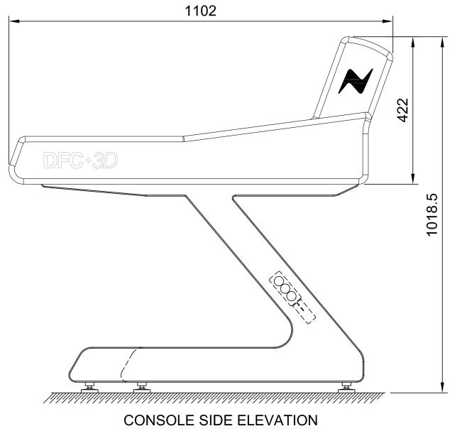
DFC consoles are built from modular sections called ‘baskets’, most commonly 16 and 24 channel baskets are used, and occasionally 8 channel baskets.
At the time of placing an order, you will be told which size sections will be used to make the console, and so the overall dimensions of the console can be calculated by adding multiples of the dimensions shown above.
For example a 32 fader single partition console would be a 24 channel basket (16 fader + 8 wide master section) and a 16 channel basket (16 faders). So the overall width will be 75mm (side trim) + 1043mm (24 basket) + 697.5mm (16 basket) + 75mm (side trim). Total 1890.5mm
Rack Data
All racks are standard 483mm (19") wide.
NOTE: ALL RACK DEPTHS BELOW DO NOT INCLUDE ALLOWANCES FOR CABLE AND CONNECTOR CLEARANCES AT THE REAR, FOR WHICH ANOTHER 150MM (6") SHOULD BE ADDED.
All weights are rounded up to the nearest whole unit.
Console Module Installation
Modules are usually shipped fitted into the console.
If for any reason they are not fitted, they will be shipped in anti-static, moulded foam containers.
They are individually labelled and should be installed in the console in accordance with the Module Installation Map provided.
• The module type is engraved on the top of each panel.
• The serial number is inscribed on the bottom board of each panel.
NOTE: PLEASE KEEP EACH FRONT PANEL WITH ITS ASSOCIATED BOARD ASSEMBLY. DO NOT SWAP FRONT PANELS FROM ONE ASSEMBLY TO ANOTHER.
When installing the following modules, please note:
Master Chanbase
Ensure the loudspeaker wiring connectors are plugged into the module i.e. the 34-way ribbon connector is plugged into J1 of the vertical volume control board, the level control ribbon cable plugged into J2 of the same board, and the relay control ribbon cable plugged into J7 of the chanbase bottom board.
Joystick
Ensure the power connector is plugged into J1 and link wiring connector is plugged into J4, with terminator connections in J5, J6 and J7 (Single twin joystick fitted).
Connecting the System
When the units are in position and all the cables have been identified and prepared, connect the system as shown in the Custom Interconnect section.
Ensure each module is fed with a suitable mains supply.
Sync Connections
Connectors are fitted on the SPS rack for AES SYNC, WCK IN, WCK OUT (Word clock), VIDEO and LOOP.
These allow connection of three types of sync.
The system can operate from any one of these (selectable by the user) or from its internal reference.
Audio Signals
All audio to the ADC modules and from the DAC modules are balance audio signals.
Automation Connections
The SPS rack has connectors for TIMECODE IN, TIMECODE OUT, TACH IN, and MACHINE CONTROL.
Console to Racks Audio Interconnect
The Audio Cable from the Console is supplied with cable ends stripped and tinned only ready for custom installation requirements.
XLR Pin Outs
| Pin | Signal |
| 1 | Screen |
| 2 | Hot |
| 3 | Cold |
and for dual circuit connectors:
• Pin 4, Phase (or Hot), second circuit (or B channel)
• Pin 5, Anti-Phase (or Cold), second circuit (or B channel)
Pin 1 for outputs is directly connected to the chassis.
Pin 1 for inputs is R.F. coupled to the chassis to provide a screen but avoiding hum loop problems. The exception is the Mic/Line Unit where pin 1 for inputs is directly connected to chassis to provide phantom power.
The shell connection of the XLR connector is a direct connection to the chassis and should be used for the O/P screen connection as this gives an improved R.F. connection and screening.
Audio Signals
All MIOS audio signals are balanced.
ADC, DAC & AES Varicon connectors
The system is supplied ready to accept standard Varicons.
All the Varicon outputs are filtered in order to provide some degree of RFI protection. This filtering is limited so as not to cause distortion in the audio domain.
In order to maintain EMC compliance and maximum levels of immunity to radio frequency interference, screened twisted pair cables should be used.
In AMS Neve's considerable experience RFI has not proved to be a problem. However the system is designed with mounting points for screening cages to be fitted to the chassis which eliminate this possibility.
These MUST be used with shielded covers to gain any benefit.
These shielding kits are available from EDAC distributors.
Console Interface Panels

Audio I/O - IMPORTANT NOTE
- Analogue Audio IO Varicon is fitted only if analogue monitor LS board is present
• For modular consoles, Basket Selector ID Panel is fitted instead of Audio I/O.

Each section of the DFC surface can have the optional ‘Basket ID selector’ on its rear panel in the place of the Analogue Monitor LS Board IO connector. This option is used when a console is modular, allowing baskets to be moved or removed.
This panel sets the IP addresses for the various components in that basket. For example the first section of a console would have Partition
set to ‘1’, Chassis in Partition set to ‘1’ (as it is the first section of partition 1) and First Meter ID set to ‘01’ (as this will be the first meter). In the example on the panel shown above this section is the beginning of the second partition, the first partition had 3 meter panels, so First Meter ID for this section is set to ‘04’.
By setting these options on the Basket ID Selectors, sections of the console can be added, removed or placed in different partitions without any other changes being made (no switch settings, not wiring changes etc.)
• If neither option is purchased, a blank panel will be fitted.
Console Connections - where analogue monitor LS board present
DAC output SEL 1 should be wired to MON 1 IN and drives the speakers connected MAIN LS OUT.
Volume is controlled by the control room pot on the console.
SEL 1 may be switched to drive the speakers connected to SMALL LS 1 OUT.
DAC output SEL 3 should be wired to MON 2 IN and drives the speakers connected to SMALL LS 2 OUT when SMALL LS 2 button is pressed or when PFL is selected.
DAC output SEL 2 should be wired to STUDIO IN and drives the speakers connected to STUDIO OUT.
The MAIN LS OUT, SMALL LS1 OUT and SMALL LS2 OUT should then be fed to the loudspeaker amplifiers.
The STUDIO IN should be fed from the DAC and the STUDIO OUT should feed the loudspeaker amplifier.
The TALKBACK OUT is the line level feed from the Talkback mic, for feeding to an ADC or an external TB system, or both.
Console Interface Panel Varicons
Audio I/O Connector, Console Interface Panel. Location: front of Master section
This connector is a 56 pin Varicon (Elco, Varelco etc) male.
The shell is coded 1:1.
| Pin | Audio I/O | |
| EFA | HotColdScreen | Studio In L* |
| BCH | HotColdScreen | Studio In R* |
| JKD | HotColdScreen | Studio Out L* |
| RSL | HotColdScreen | Studio Out R* |
| MNT | HotColdScreen | Control RoomSmall LS1 L* |
| UVP | HotColdScreen | Control RoomSmall LS1 R* |
| abW | HotColdScreen | Control RoomSmall LS2 L* |
| cdZ | HotColdScreen | Control RoomSmall LS2 R* |
| klp | HotColdScreen | Control RoomMon 1 In L* |
| mnt | HotColdScreen | Control RoomMon 1 In R* |
| uvz | HotColdScreen | Control RoomMain LS Out L* |
| AABBw | HotColdScreen | Control RoomMain LS Out R* |
| xyCC | HotColdScreen | Control RoomMon 2 In L* |
| DDEEKK | HotColdScreen | Control RoomMon 2 In R* |
| LLMMFF | HotColdScreen | T/B Mic Output |
| HHJJNN | HotColdScreen | --- |
As each AMS Neve console is unique in configuration to each customer, the I/O has to be set so that the SPS rack is aware of exactly which I/O is on each of the MADI streams.
This is set at the factory before the console is shipped.
It is therefore important that if you wish to change the I/O configuration after the console has been delivered, that you contact AMS Neve so that the I/O configuration software can also be changed.
For example, if the console has been shipped with a MIOS rack on MADI 1 and an AES box on MADI 2, it is not possible to swap these I/O units over without making a change to the I/O configuration software as well.
Optical / Coaxial connectors
A 13U USP SPS rack has 24 pairs of BNC coaxial connectors as standard on the rear of the rack, but please be aware that you will need a supporting number of Quad MADI 64 cards to support all of this I/O.
Each Quad MADI 64 card supports 4 pairs of 56/64 channel ins/outs at up to 96kHz.
As specified at the time of ordering, the rear of the SPS rack may contain a mixture of optical MADI ports and coaxial MADI ports.
Where there is an optical connector (e.g. on MADI 1), then the coaxial connectors for MADI 1 will not accept a coaxial signal if the optical connectors to the equipment are removed.
It is possible to remove the optical board to enable the coaxial connectors to work, and this would involve unhinging the rear of the unit and reconfiguring the internal wiring.
Where there are no optical connectors present on a MADI pair of ports, the coaxial connectors will work, providing there are enough Quad MADI 64 cards inside the processing rack to support them.
The number and configuration of optical and coaxial connectors is unique to every console, and rarely needs to be changed, except where older racks are upgraded to optical connections.
Machine Control Ports #1 to #5
These are located on the rear of the SPS rack and use a DE 9P connector.
They use a twisted pair screen cable with EMC hoods.
Twisted pairs should be used with Rx- Rx+ and Tx- and Tx+ as twisted pairs. The cable screen should be 360° terminated on an EMC back-shell at each end.
| Pin No | Signal |
| 1 | Gnd |
| 2 | Rx- |
| 3 | Tx+ |
| 4 | Gnd |
| 5 | RTS |
| 6 | Gnd |
| 7 | Rx+ |
| 8 | Tx- |
| 9 | Gnd |
Serial RS 422 (P2 protocol)
On the rear of the SPS rack.
Use high quality screened twisted pair cable, paying careful attention to correct pairing. Screens should be 360° terminated to EMC back-shells at both ends.
Length as required, recommended maximum, 50m

Machine Control Port #2 & #4
ES1-11 cable (also ES1-12, ES/2 Synchronet)
This is on the rear of the SPS rack.
The use of high quality screened twisted-pair cable is recommended, paying careful attention to the correct pairing.
A screened twisted-pair cable should also be used for the XLR connection with the screens connected to both ends.
Screens should be 360° terminated to EMC back-shells at both ends.
Length as required, recommended maximum is 50m.

Machine Control Port #6
On rear of SPS rack, the mating connector is a DA 15 P type.
A screened twisted pair cable should be used with the screens 360° terminated to EMC back-shells at both ends.
Signal pairs 1 & 2, 3 & 4, 5 & 6, 7 & 8, 9 & 10 and 14 & 15 should all use twisted pairs of the same cable.
| DMC | Sony 9-Pin | |
| Pin No. | Signal | Pin No. |
| 1 | Tx+(B) | 3 |
| 2 | Tx- (A) | 8 |
| 3 | Rx+(B) | 7 |
| 4 | Rx- (A) | 2 |
| 5 | TIC- (A) | |
| 6 | TIC+(B) | |
| 7 | ||
| 8 | 0v | 1 |
| 9 | CODE- (A) | |
| 10 | CODE+(B) | |
| 11 | TL EXT | |
| 12 | D-RECON | |
| 13 | MUTE | |
| 14 | FRAME- (A) | |
| 15 | FRAME+ (B) | |
| SCREEN | SCREEN (CHASSIS) | |
On rear of SPS rack, uses a DA 15 P mating connector.

Services Port
On rear of SPS rack, uses a DB 25 P mating connector.
A screened twisted-pair cable should be used with the screens 360° terminated to EMC back-shells at both ends. If this port is taken to more than one destination then all cable screens must be terminated to EMC back-shells.
| Pin No. | Signal |
| 1 | |
| 2 | |
| 3 | |
| 4 | |
| 5 | |
| 6 | |
| 7 | |
| 8 | |
| 9 | |
| 10 | |
| 11 | |
| 14 | SYNC COM |
| 15 | SYNC NC |
| 16 | SYNC NO |
| 17 | RL1 COM REC |
| 18 | RL1 NC REC |
| 19 | RL1 NO REC |
| 20 | RL2 COM PLAY/ADR |
| 21 | RL2 NC PLAY/ADR |
| 22 | RL2 NO PLAY/ADR |
SPS Rack 7U model (single-engine system)

SPS Rack 13U model (single or dual-engine system)
All connectors functions as outlined below are the same for the 7U rack. Please see section on Optical/Coaxial MADI connectors (page 15).

| TRANLINK A | No function |
| TRANLINK B | Can be used to boot a Legacy relay rack |
| TRANLINK C | No function |
| TRANLINK D | No function |
| VITC | Not used |
| WCK IN | Connect Wordclock sync from an external source using a coaxial cable and BNC connector. |
| WCK OUT | Outputs the Wordclock sync, whether this is generated from the SPS rack itself, or from an external source |
| AES SYNC IN | If synching the system to an external AES source, connect using XLR connector. |
| TIMECODE IN | If using External Timecode as a reference source, connect using an XLR connector from the timecode source. |
| TACH IN | Not used |
| MIC / LINE | Not used |
| TIMECODE OUT | The output of the consoles LTC |
| TACH OUT | Not used |
| VIDEO A | If synching the system to an external video source, connect this source using a coaxial cable and a BNC connector. |
| VIDEO B | Not used. |
| MC #1 TO MC #6 | Machine control ports. Ports #1 to #5 use the Sony 9-pin protocol, #6 can be used to connect to an ES/2 synchroniser (not supplied) |
| SERVICES | MCS tallies - see 'Service Port' section on page 21 |
| MADI IN / OUT 1 | Connect using coaxial cable and BNC connectors to the Rx/Tx Madi ports on your MIOS racks, AES 96 racks etc, observing the correct Rx/Tx and I/O configuration. |
| OPTICAL A / B 1 | Connect using optical cables to the Rx/Tx Madi ports on your MIOS racks, AES 96 racks etc. |
| POWER | Connect power supply. |
| ENCORE ETHERNET | RJ45 CAT6 Connection to Encore Processor Rack |
| CONSOLE ETHERNET | RJ45 CAT6 Connection to Console Surface |
1 With regard to optical MADI inputs and Coaxial MADI inputs, as specified at the time of ordering, please note that you should ONLY connect equipment to:
• Either MADI1 BNCs OR Optical A TX/RX
• Either MADI 2 BNCs OR Optical A TX2/RX2
• Either MADI 3 BNCs OR Optical B TX/RX
• Either MADI 4 BNCs OR Optical B TX2/RX2
The SPS rack is the main audio processing rack, into which all of the MADI signals and sync sources are input.
The 13U rack may be larger in size, but performs the same functions and (apart from the power connector), has all of the same connectors on the rear.
Encore Processor Rack

LAN Connection
(for general LAN function)
RJ45 CAT6
connection to SPS rack)
MIOS Rack
MIOS Full

MIOS Lite
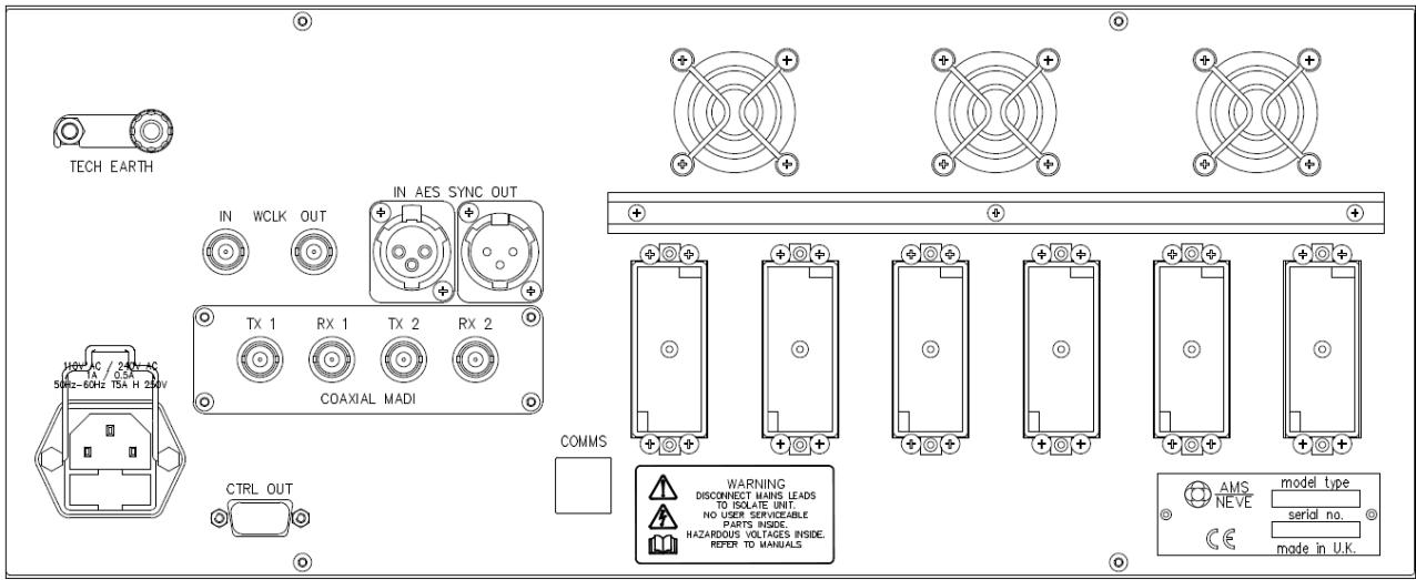
Both racks here are shown with coaxial MADI connectors. These may be optical connectors if this is specified at the time of ordering.
X LIN = where X = the number of the MADI port that the unit is connected to.
MON O/Ps 1 + 2
Must be assigned to X LIN 27 AB in Encore 3
MON O/Ps 3 + 4
Must be assigned to X LIN 28 AB in Encore 3
AES SYNC IN
If synching the unit to external AES synch, connect using XLR to the sync source.
AES SYNC OUT
If synching the unit to external AES synch, connect using XLR to the next unit in the chain.
WCLK IN / OUT
If synching to external Wordclock, connect using BNC connector
CTRL IN
Not used
CTRL OUT
Not used
GP INPUTS
Connect to external relay inputs
GP OUTPUTS
Connect to external relay outputs
COAXIAL MADI
Connect to SPS rack, using TX1 / RX1 (Only use TX2/RX2 if working at 96kHz)
56-way Edac connectors A to F
Audio inputs, See pinouts below
| Pin | Quad Mic | Octal Mic | Line In | Line Out | AES | |
| EFA | HotColdScreen | Mic In 1A | Mic 1 | Line In 1 | Line Out 1 | AES In 1/2 |
| BCH | HotColdScreen | Mic In 2A | Mic 5 | Line In 2 | Line Out 2 | AES In 3/4 |
| JKD | HotColdScreen | Mic In 2B | Mic 6 | Line In 3 | Line Out 3 | AES In 5/6 |
| RSL | HotColdScreen | Mic In 1B | Mic 2 | Line In 4 | Line Out 4 | AES In 7/8 |
| MNT | HotColdScreen | Mic In 3A | Mic 3 | Line In 5 | Line Out 5 | AES In 9/10 |
| UVP | HotColdScreen | Mic In 4A | Mic 7 | Line In 6 | Line Out 6 | AES In 11/12 |
| abW | HotColdScreen | Mic In 3B | Mic 4 | Line In 7 | Line Out 7 | AES In 13/14 |
| cdZ | HotColdScreen | Mic In 4B | Mic 8 | Line In 8 | Line Out 8 | AES In 15/16 |
| klp | HotColdScreen | Line 1 | Line In 9 | Line Out 9 | AES Out 1/2 | |
| mnt | HotColdScreen | Line 5 | Line In 10 | Line Out 10 | AES Out 3/4 | |
| uvz | HotColdScreen | Line 2 | Line In 11 | Line Out 11 | AES Out 5/6 | |
| AABBw | HotColdScreen | Line 6 | Line In 12 | Line Out 12 | AES Out 7/8 | |
| xyCC | HotColdScreen | Line In 2 | Line 7 | Line In 13 | Line Out 13 | AES Out 9/10 |
| DDEEKK | HotColdScreen | Line In 1 | Line 3 | Line In 14 | Line Out 14 | AES Out 11/12 |
| LLMMFF | HotColdScreen | Line In 3 | Line 4 | Line In 15 | Line Out 15 | AES Out 13/14 |
| HHJJNN | HotColdScreen | Line In 4 | Line 8 | Line In 16 | Line Out 16 | AES Out 15/16 |
All audio connectors on the rear panel are 56 pin Varicon (Elco, Varelco, etc) male.
Each of the four mics is selectable from either an A or B input, hence the two inputs shown below for the same port.
GP Inputs (not available on MIOS Lite)
There are 8 general purpose opto-isolated inputs on a 25-way D-type male connector.
The GP inputs can either be driven using external logic signals, or by switches using the rack's +5V and GND supply pins.
If using an external logic signal, connect an external ground to the input return pins.
If using the internal +5V and GND pins, GND should be connected to the input return pins. An internal resistor on the opto inputs limits the current.
Connect anode to +5v to operate the opto.
| Opto | Pin number | Signal |
| 1 | 1 | Opto 1 anode |
| 2 | 2 | Opto 2 anode |
| 3 | 3 | Opto 3 anode |
| 4 | 4 | Opto 4 anode |
| 5 | 5 | Opto 5 anode |
| 6 | 6 | Opto 6 anode |
| 7 | 7 | Opto 7 anode |
| 8 | 8 | Opto 8 anode |
| 13 | Input return (cathodes) | |
| 25 | Input return (cathodes) | |
| 11 | +5v | |
| 23 | +5v | |
| 12 | GND | |
| 24 | GND |
GP Outputs (not available on MIOS Lite)
There are 8 general purpose opto-isolated outputs on a 25-way D-type male connector.
| Relay | Pin number | Signal |
| 1 | 1 | NO |
| 2 | NC | |
| 14 | COMMON | |
| 2 | 15 | NO |
| 16 | NC | |
| 3 | COMMON | |
| 3 | 4 | NO |
| 5 | NC | |
| 17 | COMMON | |
| 4 | 18 | NO |
| 19 | NC | |
| 6 | COMMON | |
| 5 | 7 | NO |
| 8 | NC | |
| 20 | COMMON | |
| 6 | 21 | NO |
| 22 | NC | |
| 9 | COMMON | |
| 7 | 10 | NO |
| 11 | NC | |
| 23 | COMMON | |
| 8 | 24 | NO |
| 25 | NC | |
| 12 | COMMON | |
| Chassis | Screen |
MON FAC (Monitor Facilities Panel)

DFC Control IN
| Pin number | Signal | Description |
| 1 | Chassis | |
| 2 | nDIM | When low, dim output level by 20dB |
| 3 | VCNTRL | Voltage control of monitor level |
| 4 | 79/VAR | When high, set output level using 79/VAR preset |
| 5 | Gnd | |
| 6 | 5v Ref | Via NAP 2 |
| 7 | DIRECT | When high, set ignore VCNTRL but use pins 4 & 8 |
| 8 | 85 sB SPL | When high, set output level using 85dB SPL preset |
| 9 | Gnd |
Multichannel AES I/O Unit

The diagram above shows coaxial MADI connectors, but these may be Optical MADI connectors as specified at the time of ordering.
The PSU HEALTHY, CTRL IN and CTRL OUT 9-pin connectors are not used.
As standard, these units have 24 ins/24 outs, although these can be expanded by adding optional 'daughter' boards to provide extra ins/outs. Please specify this at the time of ordering.
Connect the Rx/Tx MADI connectors to the appropriate MADI ports on the rear of the SPS rack.
Rear of unit, 37-way D-type, male.
| Pin number | Signal Type | Channel |
| 37 | Hot | |
| 36 | Cold | AES 1 AB In |
| 18 | Screen | |
| 17 | Hot | |
| 16 | Cold | AES 2 AB In |
| 35 | Screen | |
| 43 | Hot | |
| 33 | Cold | AES 3 AB In |
| 15 | Screen | |
| 14 | Hot | |
| 13 | Cold | AES 4 AB In |
| 32 | Screen | |
| 31 | Hot | |
| 30 | Cold | AES 5 AB In |
| 12 | Screen | |
| 11 | Hot | |
| 10 | Cold | AES 6 AB In |
| 29 | Screen | |
| 28 | Hot | |
| 27 | Cold | AES 7 AB In |
| 9 | Screen | |
| 8 | Hot | |
| 7 | Cold | AES 8 AB In |
| 26 | Screen | |
| 25 | Hot | |
| 24 | Cold | AES 9 AB In |
| 6 | Screen | |
| 5 | Hot | |
| 4 | Cold | AES 10 AB In |
| 23 | Screen | |
| 22 | Hot | |
| 21 | Cold | AES 11 AB In |
| 3 | Screen | |
| 2 | Hot | |
| 1 | Cold | AES 12 AB In |
| 20 | Screen |
Rear of unit, 37-way D-type, male
| Pin number | Signal Type | Channel |
| 37 | Hot | |
| 36 | Cold | AES 1 AB Out |
| 18 | Screen | |
| 17 | Hot | |
| 16 | Cold | AES 2 AB Out |
| 35 | Screen | |
| 43 | Hot | |
| 33 | Cold | AES 3 AB Out |
| 15 | Screen | |
| 14 | Hot | |
| 13 | Cold | AES 4 AB Out |
| 32 | Screen | |
| 31 | Hot | |
| 30 | Cold | AES 5 AB Out |
| 12 | Screen | |
| 11 | Hot | |
| 10 | Cold | AES 6 AB Out |
| 29 | Screen | |
| 28 | Hot | |
| 27 | Cold | AES 7 AB Out |
| 9 | Screen | |
| 8 | Hot | |
| 7 | Cold | AES 8 AB Out |
| 26 | Screen | |
| 25 | Hot | |
| 24 | Cold | AES 9 AB Out |
| 6 | Screen | |
| 5 | Hot | |
| 4 | Cold | AES 10 AB Out |
| 23 | Screen | |
| 22 | Hot | |
| 21 | Cold | AES 11 AB Out |
| 3 | Screen | |
| 2 | Hot | |
| 1 | Cold | AES 12 AB Out |
| 20 | Screen |
AUX AES-EBU IN 25-56, Optional Expansion 1 or 2 cards
Rear of unit, 50-way D-type, male
| Pin number | Signal Type | Channel | |
| 1 Exp card | 2 Exp card | ||
| 33 | Hot | ||
| 49 | Cold | AES 13 AB In | AES 13 AB In |
| 16 | Screen | ||
| 15 | Hot | ||
| 32 | Cold | AES 14 AB In | AES 14 AB In |
| 48 | Screen | ||
| 31 | Hot | ||
| 47 | Cold | AES 15 AB In | AES 15 AB In |
| 14 | Screen | ||
| 13 | Hot | ||
| 30 | Cold | AES 16 AB In | AES 16 AB In |
| 46 | Screen | ||
| 29 | Hot | ||
| 45 | Cold | AES 17 AB In | AES 17 AB In |
| 12 | Screen | ||
| 11 | Hot | ||
| 28 | Cold | AES 18 AB In | AES 18 AB In |
| 44 | Screen | ||
| 27 | Hot | ||
| 43 | Cold | AES 19 AB In | AES 19 AB In |
| 10 | Screen | ||
| 9 | Hot | ||
| 26 | Cold | AES 20 AB In | AES 20 AB In |
| 42 | Screen | ||
| 25 | Hot | ||
| 41 | Cold | AES 21 AB In | |
| 8 | Screen | ||
| 7 | Hot | ||
| 24 | Cold | AES 22 AB In | |
| 40 | Screen | ||
| 23 | Hot | ||
| 39 | Cold | AES 23 AB In | |
| 6 | Screen | ||
| 5 | Hot | ||
| 22 | Cold | AES 24 AB In | |
| 38 | Screen | ||
| 21 | Hot | ||
| 37 | Cold | AES 25 AB In | |
| 4 | Screen | ||
| 3 | Hot | ||
| 20 | Cold | AES 26 AB In | |
| 36 | Screen | ||
| 19 | Hot | ||
| 35 | Cold | AES 27 AB In | |
| 2 | Screen | ||
| 1 | Hot | ||
| 18 | Cold | AES 28 AB In | |
| 34 | Screen | ||
Rear of unit, 50-way D-type, male
| Pin number | Signal Type | Channel | |
| 3 Exp card | 4 Exp card | ||
| 33 | Hot | ||
| 49 | Cold | AES 13 AB Out | AES 13 AB Out |
| 16 | Screen | ||
| 15 | Hot | ||
| 32 | Cold | AES 14 AB Out | AES 14 AB Out |
| 48 | Screen | ||
| 31 | Hot | ||
| 47 | Cold | AES 15 AB Out | AES 15 AB Out |
| 14 | Screen | ||
| 13 | Hot | ||
| 30 | Cold | AES 16 AB Out | AES 16 AB Out |
| 46 | Screen | ||
| 29 | Hot | ||
| 45 | Cold | AES 17 AB Out | AES 17 AB Out |
| 12 | Screen | ||
| 11 | Hot | ||
| 28 | Cold | AES 18 AB Out | AES 18 AB Out |
| 44 | Screen | ||
| 27 | Hot | ||
| 43 | Cold | AES 19 AB Out | AES 19 AB Out |
| 10 | Screen | ||
| 9 | Hot | ||
| 26 | Cold | AES 20 AB Out | AES 20 AB Out |
| 42 | Screen | ||
| 25 | Hot | ||
| 41 | Cold | AES 21 AB Out | |
| 8 | Screen | ||
| 7 | Hot | ||
| 24 | Cold | AES 22 AB Out | |
| 40 | Screen | ||
| 23 | Hot | ||
| 39 | Cold | AES 23 AB Out | |
| 6 | Screen | ||
| 5 | Hot | ||
| 22 | Cold | AES 24 AB Out | |
| 38 | Screen | ||
| 21 | Hot | ||
| 37 | Cold | AES 25 AB Out | |
| 4 | Screen | ||
| 3 | Hot | ||
| 20 | Cold | AES 26 AB Out | |
| 36 | Screen | ||
| 19 | Hot | ||
| 35 | Cold | AES 27 AB Out | |
| 2 | Screen | ||
| 1 | Hot | ||
| 18 | Cold | AES 28 AB Out | |
| 34 | Screen | ||
Status Panel (front)

Connector: J6
Location - Console upper centre, rear of Status Panel. For access, remove the rear panel.
Mating connector, 10 way IDC Bump polarised socket
| Pin | Signal |
| 1 | Gnd |
| 2 | Gnd |
| 3 | Alarm 1 |
| 4 | Alarm 2 |
| 5 | O/L |
| 6 | Solo |
| 7 | Record |
| 8 | Rehearse |
| 9 | No connection |
| 10 | No connection |
Connect the respective pin to ground to illuminate the required display.
Current rating: 60mA per LED
The LED brightness can be adjusted using VR1
The six LEDs can be placed under software control via the J6 to J11 / J12 connection cable, such that operation of relays 1 to 6 will light LEDs ALARM 1, ALARM 2, O/L, SOLO, RECORD & REHEARSE respectively.
Relays 7 and 8 are operated using the Control Room DIM and TALKBACK buttons respectively.
Connectors J11 & J 12 – Relay Output
Location - Console upper centre, rear of Status Panel. For access, remove the rear panel.
Contact rating, 90 watts DC at 40 volts max
Mating connector, 26 way IDC Bump polarised socket.
Status Panel (rear)

| J 11 | ||
| Pin | Relay number | |
| 1 | R 1 | I 1 |
| 2 | I 2 | |
| 3 | 1 A | |
| 4 | 2 A | |
| 5 | 1 B | |
| 6 | 2 B | |
| 7 | R 2 | I 1 |
| 8 | I 2 | |
| 9 | 1 A | |
| 10 | 2 A | |
| 11 | 1 B | |
| 12 | 2 B | |
| 13 | R 3 | I 1 |
| 14 | I 2 | |
| 15 | 1 A | |
| 16 | 2 A | |
| 17 | 1 B | |
| 18 | 2 B | |
| 19 | R 4 | I 1 |
| 20 | I 2 | |
| 21 | 1 A | |
| 22 | 2 A | |
| 23 | 1 B | |
| 24 | 2 B | |
| 25 | Gnd | |
| 26 | Gnd | |
| J 12 | ||
| Pin | Relay number | |
| 1 | R 5 | I 1 |
| 2 | I 2 | |
| 3 | 1 A | |
| 4 | 2 A | |
| 5 | 1 B | |
| 6 | 2 B | |
| 7 | R 6 | I 1 |
| 8 | I 2 | |
| 9 | 1 A | |
| 10 | 2 A | |
| 11 | 1 B | |
| 12 | 2 B | |
| 13 | R 7 | I 1 |
| 14 | I 2 | |
| 15 | 1 A | |
| 16 | 2 A | |
| 17 | 1 B | |
| 18 | 2 B | |
| 19 | R 8 | I 1 |
| 20 | I 2 | |
| 21 | 1 A | |
| 22 | 2 A | |
| 23 | 1 B | |
| 24 | 2 B | |
| 25 | Gnd | |
| 26 | Gnd | |
| Relay number | Function |
| 1 | Alarm 1 ('Automation Locked' tally) |
| 2 | Swap Speakers (Sound One Speaker changeover or Dolby Remote Input) |
| 3 | Digital Overload (as set in Encore Preferences) |
| 4 | Solo Status |
| 5 | Remote Solo Clear (twin DSP systems only) |
| 6 | Cut Status |
| 7 | Dim Status |
| 8 | Talkback Status |
Connector J4
Location - Console upper centre, rear of Status Panel. For access, remove the rear panel.
Mating connector, 20 way IDC Bump polarised socket.
| Pin number | Signal |
| 1 | Gnd |
| 2 | Gnd |
| 3 | |
| 4 | Input 1 |
| 5 | |
| 6 | Input 2 |
| 7 | |
| 8 | Input 3 |
| 9 | |
| 10 | Input 4 |
| 11 | |
| 12 | Input 5 |
| 13 | |
| 14 | Input 6 |
| 15 | |
| 16 | Input 7 |
| 17 | |
| 18 | Input 8 |
| 19 | Vcc |
| 20 | Vcc |
Inputs 1 – 8 are under software control.



- DFC3D
- INSTALLATION GUIDE
- INSTALLING DFC3D
- STATIC SENSITIVE DEVICES – HANDLING PRECAUTIONS
- CONSOLE MODULE INSTALLATION
- CONSOLE INTERFACE PANELS
- CONSOLE INTERFACE PANEL VARICONS
- OPTICAL / COAXIAL CONNECTORS
- MACHINE CONTROL PORTS #1 TO
- MACHINE CONTROL PORT
- SERVICES PORT
- SPS RACK 7U MODEL (SINGLE-ENGINE SYSTEM)
- SPS RACK 13U MODEL (SINGLE OR DUAL-ENGINE SYSTEM)
- ENCORE PROCESSOR RACK
- MIOS RACK
- GP INPUTS (NOT AVAILABLE ON MIOS LITE)
- GP OUTPUTS (NOT AVAILABLE ON MIOS LITE)
- MON FAC (MONITOR FACILITIES PANEL)
- MULTICHANNEL AES I/O UNIT
- IMPORTANT NOTE
- INITIAL CHECKS
- INTRODUCTION
- COMPONENT AND PACKAGE IDENTIFICATION FROM AMS NEVE LIMITED
- GENERAL PRECAUTIONS
- STATIC SENSITIVE DEVICES TO BE RETURNED TO AMS NEVE LIMITED
- CABLE LENGTHS
- RACK MOUNTING
- COOLING
- TECHNICAL EARTH
- SAFETY EARTH
- MAINS POWER
- CONSOLE DATA
- RACK DATA
- NOTE: PLEASE KEEP EACH FRONT PANEL WITH ITS ASSOCIATED BOARD ASSEMBLY. DO NOT SWAP FRONT PANELS FROM ONE ASSEMBLY TO ANOTHER
- MASTER CHANBASE
- JOYSTICK
- CONNECTING THE SYSTEM
- SYNC CONNECTIONS
- AUDIO SIGNALS
- AUTOMATION CONNECTIONS
- CONSOLE TO RACKS AUDIO INTERCONNECT
- ADC, DAC & AES VARICON CONNECTORS
- AUDIO I/O - IMPORTANT NOTE
- CONSOLE CONNECTIONS - WHERE ANALOGUE MONITOR LS BOARD PRESENT
- AUX AES-EBU IN 25-56, OPTIONAL EXPANSION 1 OR 2 CARDS
- STATUS PANEL (FRONT)
- CONNECTOR: J
- CONNECTORS J11 & J 12 – RELAY OUTPUT
- CONNECTOR J
Brand : AMS Neve
Model : DFC3D
Category : Audio Console