
nx 16500 -48 - Hybrid inverter STUDER - Free user manual and instructions
Find the device manual for free nx 16500 -48 STUDER in PDF.


| Product type | Hybrid inverter charger from the STUDER NEXT range, single-phase, off-grid / on-grid |
| Brand and model | STUDER nx 16500 -48 (next1 series) |
| Nominal AC output power | 4500 VA continuous at 25 °C; 6500 VA for 30 min; 12000 VA for 5 s |
| Output voltage | Pure sine wave 220/230/240 Vac (±1 %) |
| Output frequency | 50/60 Hz (±0.02 %) |
| Battery voltage | 48 Vdc nominal, input range 38 - 68 Vdc |
| Maximum battery charging | 125 Adc / 6250 W |
| AC source current rating | 80 Aac maximum |
| AC-Flex current rating | 50 Aac maximum, configurable as source or loads |
| Dimensions | Wall mounted 182 x 439 x 580 mm; 19-inch rack version 175 (3U) x 420 x 550 mm |
| Weight | 39 kg product weight, 42 kg transport weight |
| Ingress protection | IP65 |
| Communications | 2x nx communication bus RJ45/8, CAN BMS, RS485i, Ethernet, Wi-Fi, USB |
| Multi-unit operation | Up to 3 units in parallel, three-phase or split-phase configuration |
| Key operating modes | Off-grid, on-grid, self-consumption optimization, backup readiness, zero grid-feeding, Smart-Boost |
| Battery compatibility | Lead-acid and lithium batteries; CAN BMS communication with major brands |
| Integration | AC-coupled solar inverters and Studer Vario solar chargers via xcom485i-nx bridge |
| Safety features | Grid fault ride-through, reactive power management, overload and short-circuit protection, internal lightning protection |
| Installation | Wall mounted or 19-inch rack; must be installed by qualified personnel |
| Maintenance | No particular maintenance required; regularly check ventilation and connection tightness |
| Spare parts and repairability | Repairs by qualified personnel only; use original Studer parts; surge protection devices are single-use and require factory repair |
| Certifications | CE, LVD 2014/35/EU, EMC 2014/30/EU, RoHS; grid codes EN50549-1, VDE-AR-N 4105, CEI 0-21 |
Frequently Asked Questions - nx 16500 -48 STUDER
User questions about nx 16500 -48 STUDER
0 question about this device. Answer the ones you know or ask your own.
Ask a new question about this device
Download the instructions for your Hybrid inverter in PDF format for free! Find your manual nx 16500 -48 - STUDER and take your electronic device back in hand. On this page are published all the documents necessary for the use of your device. nx 16500 -48 by STUDER.
USER MANUAL nx 16500 -48 STUDER
next 1

Detailed Tech Manual

Smart hybrid inverter charger with embedded communication
nx1 6500-48
AC options:
230V/50Hz
Casing options:
wall mounted

Accessories in option:
Display for control and communication...... nx interface
Battery temperature sensor.... nx tempSensor
Cables for communication.... nx-ethernetCab-1m (ethernet, cat5, 26AWG)
Communication to Vario solar chargers...... xcom-485i-nx
Powermeter for house introduction measurement ... energy metering 3-PH
Contents
1 INTRODUCTION 4
2 GLOSSARY 5
2.1 Symbols and conventions....5
2.2 Models naming 6
3 GENERAL INFORMATION......7
3.1 About this user manual....7
3.2 Important safety instructions....8
3.3 Quality and warranty 9
3.3.1 Exclusion of warranty....9
3.3.2 Exclusion of liability 9
4 HANDLING AND MOUNTING 10
4.1 Handling and moving.... 10
4.2 Storage....10
4.3 Dimensions....10
4.4 Unpacking and mounting.... 11
4.4.1 Mounting place 11
4.4.2 Unpacking and mounting process.... 12
5 WIRING 17
5.1 General overview 17
5.1.1 System block diagram 17
5.1.2 General recommendations 18
5.1.3 Connections overview.... 19
5.1.4 Max permissible cable cross-sections, tightening torques 21
5.2 Connecting the AC (Alternative Current) 22
5.2.1 Sizing of AC protective devices.... 23
5.2.2 AC Neutral and Earthing system.... 25
5.3 Connecting the battery 27
5.3.1 Earthing of battery 28
5.3.2 Battery with communicating BMS: CAN connection.... 29
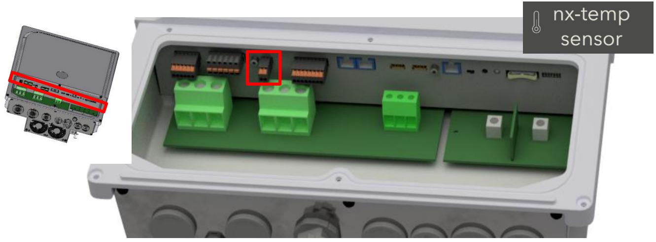
5.3.3 Battery temperature sensor connection (nx-tempSensor in option) 30
5.3.4 Notes on batteries 31
5.4 Lightning protection 33
5.5 Connecting the communications cables.... 33
5.5.1 Connecting the Studer communications cables 33
5.5.2 Connection of the nx-interface (option) 35
5.5.3 Connection to Internet 36
5.6 Wiring auxiliary I/O 37
5.6.1 Command inputs: digital and analog Inputs.... 38
5.6.2 Auxiliary relays 39
5.6.3 USB ports 41
5.6.4 Isolated communication: RS485i and CAN BMS 41
5.7 Multi-unit configurations.... 42
5.7.1 Parrallelling AC in multi-unit 43
5.7.2 Batteries in multi-units 46
5.7.3 Extension of an existing installation.... 46
5.8 Special configurations.... 47
5.8.1 AC-solar: connection of solar inverter in AC-coupling 47
5.8.2 DC-solar: integration of Studer solar chargers Vario in the system 49
5.8.3 Minigrids with AC-coupling.... 51
POWER-UP OF THE EQUIPMENT....52
6.1 Initial configuration required 52
6.2 Front panel Button 52
6.3 Front panel LED indicator....53
6.4 Beep indicator (Buzzer) 54
7 USER INTERFACE: THE EMBEDDED WEB INTERFACE 55
7.1 First commissioning with the web interface 56
7.1.1 Minimal commissionning information....58
7.1.2 Configuration Wizard 58
7.1.3 Use of wifi client at the end of the process 59
7.1.4 DNS troubleshooting: "page not found" 59
7.1.5 Gateway connectivity check....61
7.1.6 Troubleshooting: Manual reset of factory settings for gateway connectivity 62
8 OPERATION AND PERFORMANCES 64
8.1 Grid connection operating range 65
8.1.1 Continuous operating range 65
8.1.2 Grid fault ride-through capability....65
8.2 Special reactive power functionalities for grid management 66
8.3 Power limitation within DACHCZ zone 68
8.4 Behaviour in case of troubles 69
8.5 Power rating and derating 70
8.5.1 nx1 6500-48....70
9 MAINTENANCE OF THE INSTALLATION....71
10 TECHNICAL DATA 72
11 CONFORMITY....73
11.1 Grid certifications....73
12 PRODUCT RECYCLING....73
1 INTRODUCTION
Congratulations! You are about to install and use equipment from the Studer NEXT range. You have chosen a high-tech converter that will play a central role in energy installation. The NEXT range is a family of hybrid inverters, with or without solar chargers included. All models are designed with Swiss quality to have outstanding performances and robustness.
The next1 has been designed to work as a single-phase battery inverter working in both modes “off-grid” and “on-grid”. Its advanced and completely configurable functionalities will guarantee the perfect functioning of your energy system in any situation. It is available in wall mounted but can be installed in a 19’’ cabinet.
The battery charge profile may be set freely according to the battery type or the operation mode. The charging voltage is corrected in function of the temperature thanks to the external sensor nx-tempSensor (option). When using lithium batteries, the next 1 communicates with battery BMS through a CAN-bus and ensures an optimal operation according to the manufacturer of the battery. It is compatible with a large range of batteries.
On the electrical grid, the next1 is compliant with major grid-codes. The energy can be managed with different modes such as self-consumption optimization, backup readiness or zero-gridfeeding. According to the selected programming, the solar can recharge the battery, be injected to the grid or used for self-consumption only.
The parallel and three-phased operation of several inverters is possible and offers modularity and flexibility enabling an optimum dimensioning of your system according to your energy and power requirements. Working together, these different devices have a synchronized behavior for better management of the battery and of the solar resource.
The control, display and programming are done with your smartphone or your computer thanks to the embedded web interface. The nx-interface screen is optionally available for those who still prefer a dedicated physical screen.
The communication interface connects the energy system to the remote monitoring web portal https://portal.studer-innotec.com for distant supervision. The remote supervision can also be done with the APP Studer Monitoring, available for both iOS and Android.
Please read this manual carefully to ensure the perfect start up and operation of your system. The installation of such a system requires special expertise and may only be carried out by qualified personnel familiar with the local standards in force.
2 GLOSSARY
• AC: Alternative Current
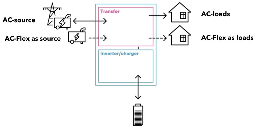
- Transfer: have the device in transfer means be connected to the AC-source with the internal relay. In that case the voltage at output is the same as the voltage at input, there is a direct connection. The inverter switches to a current source mode. The next1 transfer relay is rated 80A.
• PE: Protective Earth
- AC-Source: The AC-Source is a physical connection for AC phase, neutral and PE where the voltage source is connected. That is generally the grid or a genset.
- AC-Loads: The AC-Loads is a physical connection for AC phase, neutral and PE where the consumers that are backed-up by the battery are connected.
- AC-Flex: The AC-Flex is a physical connection for AC phase, neutral and PE. It can be configured for a use as a secondary AC source, or for a use as a controlled secondary AC loads. The maximal current in the AC-Flex relay is 50A.
- Solid neutral: when the AC-Source and the AC-Loads neutral are physically connected with a bridging cable.
2.1 SYMBOLS AND CONVENTIONS
| This symbol is used to indicate safety instructions, which, if not followed, could result in a risk of electrical shock with possible serious personal injury or death to the operator or the user. | |
| This symbol is used to indicate a risk of material damage and/or the cancellation of the guarantee. | |
| This symbol is used to indicate a procedure or function that is important for the safe and correct use of the equipment. Failure to respect these instructions may lead to the cancellation of the guarantee or to a non-compliant installation. | |
| This symbol placed on the product indicates that its surfaces may reach temperatures higher than 60°C. | |
| This symbol placed on the product indicates that its use must follow the instructions in the user manual. | |
| PE= protective earth (connected to the enclosure of the device). |
2.2 MODELS NAMING
The various next1 models are identified with the following way:
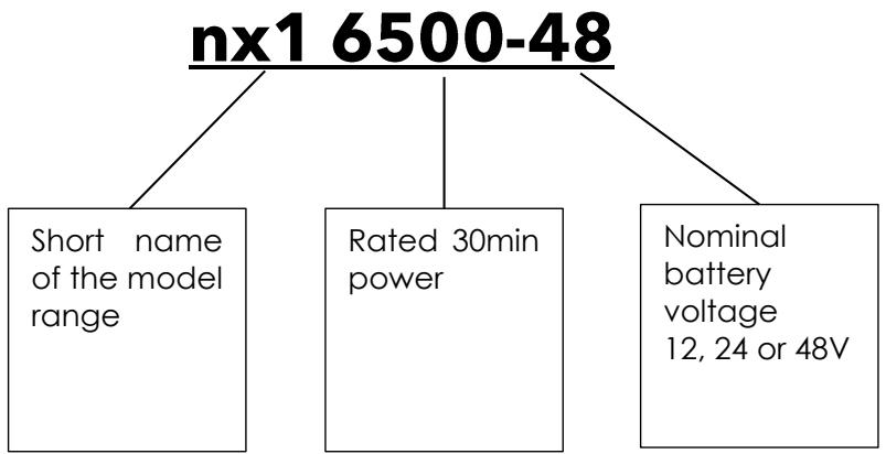
This manual applies exclusively to the following models:
| Name | Battery | Casing | AC | UL certification for US market | CE certification for other markets |
| nx1 6500-48 | 48V | Wall mounted | 50Hz/230V | YES |
3 GENERAL INFORMATION
3.1 ABOUT THIS USER MANUAL
This manual contains all the necessary information and procedures to install and use the next1 hybrid inverters. It is the most detailed documentation about this product. See the nextOS manual for the use of the nx-interface (in option) or web interface.
A summary is provided in the Quick Installation Guide, delivered with the product in a printed version.

It does not contain information about photovoltaic modules (PV) or batteries of various brands that can be connected. For this kind of information, please refer to the instructions of each specific manufacturer.
It does not contain specific information on national rules/regulations about electrical installation. It contains only safety requirements about the use of the device next1 according to following International and European standards; IEC/EN 62109 for power converters used in photovoltaic systems and IEC/EN 62477 for power converters used in general systems.
This manual covers the next1 following models and accessories in option:
• Hybrid inverter charger nx1 6500-48 with software version from 1.3.32.0
• Interface: nx interface with software version from 1.3.32.0
• Battery temperature sensor: nx tempSensor

This manual is an integral part of the equipment and must be kept available for the operator and/or the installer. It is provided under digital form in the USB-key delivered with every unit.
The latest version of the manuals can be downloaded on Studer website: https://www.studer-innotec.com

The content of this manual is copyrighted by Studer-Innotec SA, Rue des Casernes 57, 1950 Sion, Switzerland
3.2 IMPORTANT SAFETY INSTRUCTIONS
This manual contains important safety instructions. Please carefully read the safety and operation instructions before using a next1 device. Take into consideration all the warnings mentioned both on the equipment and in this manual, following all the instructions regarding the operation and use. The installation and commissioning of the next1 must be entrusted to qualified personnel. The installation and use must comply with the local safety instructions, laws, and standards in force in the country.
Do not excess the maximum rated characteristics of the equipment shown on the Type label and in the datasheet.
| HIGH-VOLTAGE DC AND AC INSIDE THE DEVICE: DANGER OF DEATHWhen the next1 is under operation, it generates voltages that can be potentially lethal (230Vac and up to 400Vac in three-phase configuration for the 230V models). Any work on or close to the installation must be carried out only by thoroughly trained and qualified personnel. Do not try to carry out ordinary maintenance on this product yourself.The next1 is in overvoltage category III (OVCIII) on AC side, in accordance with the safety standard IEC/EN 62109-1.While working on the electrical installation, it is important to make sure that the source of DC voltage coming from the battery as well as the source of DC voltage coming from the photovoltaic generator, have been disconnected from the electrical installation.Also make sure the sources of AC voltage coming from a generator or network have been disconnected from the electrical installation.Even when the next1 is disconnected from the power sources, a potentially dangerous voltage may remain at the terminals (capacitors). To eliminate this, you must waitfor at least 120 secondsto allow the electronics to be discharged.After disconnection, check all the terminals voltage with a multimeter in AC and DC modes. The connections compartment can then be opened, and the task carried out safely. All other cover parts of the device shall never be opened without written authorization by Studer Innotec SA company.The next1 can be installed at altitude up to 3000m. For installations at higher altitude, please contact Studer Innotec SA. |
Nobody is authorized to proceed with any change, modification, or repair of the equipment without the prior written authorization of Studer Innotec. Use only original parts for any authorized modification or replacement.
3.3 QUALITY AND WARRANTY
During the production and assembly of the next1, each unit undergoes several checks and tests which strictly comply with established procedures and device safety requirements. The manufacturing, assembling, and testing of each next1 are entirely carried out in our factory in Sion (CH). The warranty for this equipment depends upon the strict application of the instructions in this manual.
The next1 inverter has a ten (10) years warranty (starting from the date of purchase) against material and manufacturing defaults. The defective product will be either repaired or replaced at the discretion of Studer Innotec. A warranty extension is possible with the Studer Care+ program, giving also other advantages. Contact Studer-Innotec to know more about this program.
3.3.1 Exclusion of warranty
No warranty claims will be accepted for damages resulting from handling, use or treatment that are not explicitly mentioned in this manual. Damages arising from the following causes are excluded from the warranty:
• Voltage higher than 70V across battery terminals.
• Accidental presence of liquids in the equipment or oxidation due to condensation.
• Damage resulting from falls or mechanical shocks.
• Use of the device outside its specification
- Modifications carried out without the explicit authorization of Studer Innotec.
- Nuts or screws that have been too much or not tightened during the installation or maintenance.
• Damage due to atmospheric surge voltage (lightning).
- Damage due to inappropriate transportation or packaging.
• Damages due to improper installation
- Disappearance of original identification marks.

Never take off or damage the rating plate showing the serial number. It enables to check and follow up the data specific to each equipment and is necessary for any warranty claim.
3.3.2 Exclusion of liability
The installation, commissioning, use, maintenance, and servicing of the next1 cannot be subject of monitoring by Studer Innotec. Therefore, we disclaim all responsibility and liability for damage, costs or losses resulting from an installation that does not comply with the instructions, a faulty operation or inadequate maintenance. The use of Studer Innotec equipment is in any case under the responsibility of the customer.
This equipment is neither designed nor guaranteed to supply installations used for vital medical care nor any other critical installation entailing potential risks of important damage to people or to the environment.
We assume no responsibility for the infringement of patent rights or other third parties' rights resulting from the use of the inverter.
Studer Innotec reserves the right to make any modifications to the product without prior notification. Studer Innotec is not liable for incidental, direct or indirect damages of any kind, including any profit loss, revenue loss or damage caused to equipment or goods due to defective equipment.
4 HANDLING AND MOUNTING
4.1 HANDLING AND MOVING
The weight of the next1 with the package is about 35kg. Use an appropriate lifting method as well as help from a third party when installing the equipment.
4.2 STORAGE
The equipment must be stored in a dry environment at an ambient temperature between -20°C and 60°C . Store it in the location where it is to be used a minimum of 24 hours before commissioning to avoid thermal shocks and condensation problems.

4.3 DIMENSIONS
The next1 is 580 x 439 x 182 mm.
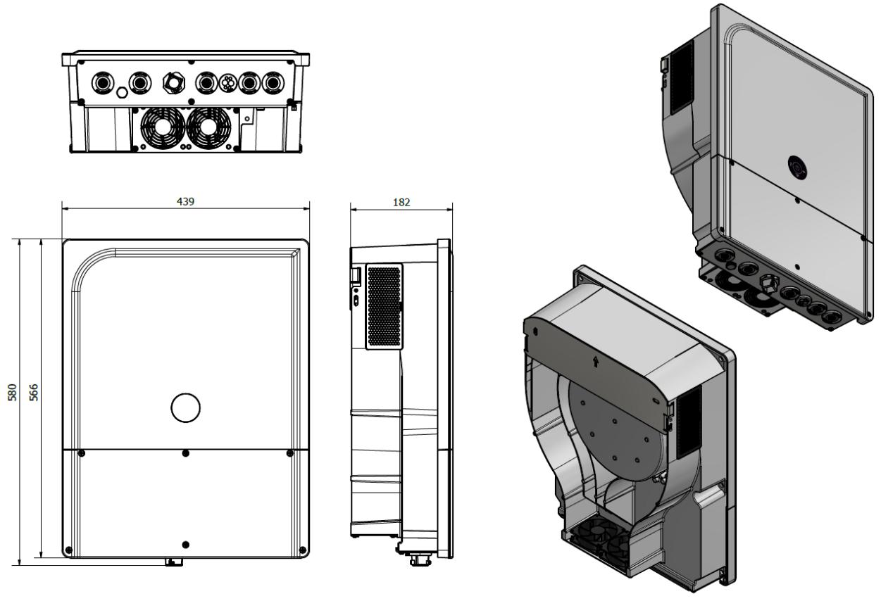
If the next1 is installed in a closed cabinet, it must have sufficient ventilation to guarantee that the ambient temperature is kept within the operating limits of the next1.
4.4 UNPACKING AND MOUNTING
When unpacking, check that the next1 has not been damaged during transport and that all accessories listed below are present. Any fault must be immediately reported to the product distributor, or the contact mentioned at the back of this manual. Check carefully the packaging as well as the next1.
Contents:
- Quick Installation Guide and webserver interface guide
- Next1 inverter-charger
• 2x Ventilation grids
• Antenna for Wi-Fi connexion (mounted)
• USB memory for datalog
• Male connectors for - CAN lithium battery communication
○ RS485 - for 2 AUX contacts
- for 2 CMD inputs
- Mounting plate (for wall mounted version). Screws for the wall are provided.
Beware of the antenna mounted on the side of the unit during handling.

4.4.1 Mounting place
Next1 is designed for indoor or outdoor use (IP65) but with batteries next to it, it is generally better to have it indoor.
The location of installation must satisfy the following criteria:
- Protected from any unauthorized person.
- Protected from water and dust and in a place with no condensation.
- It must not be situated directly above vented lead acid batteries, or in a cabinet with it, due to corrosive gas.
- No easily inflammable material should be placed directly underneath or close to the next1.
- Ventilation holes must always remain clear and be at least 20cm from any obstacle that may affect the ventilation of the equipment (see mounting schematics).
- In mobile applications, it is important to select an installation site that ensures the lowest possible vibration level.
- Protected from direct solar radiation or heat sources.
As much as possible, reduce exposure to sudden temperature variation: important heat variation may create undesired and harmful condensation inside the equipment.
4.4.2 Unpacking and mounting process
- Unpack the nx1. Use the ventilations hole on the top side of the next1 for grabbing it.

- Take the Quickguide, the fixation structure, check the content.

- Fix the mounting plate on the wall, leaving enough space around the unit for the ventilation and cabling.

2x


Screws are provided in the package.
For the wall mounting plate, use 2 screws and buffers capable to stand the weight of the inverter in full safety.
When drilling the holes respect the clearance around the device:
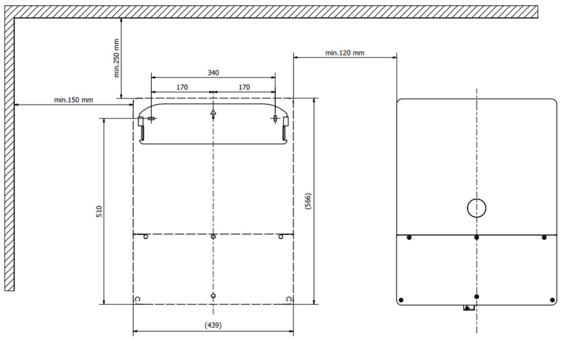
It must be installed vertically on a flat wall. Distances of at least 12cm around the units and 25cm above the equipment are required to guarantee adequate ventilation. Keep sufficient space below for the cabling. If there is a gap between the unit and the wall, that is fine, don't try to obstruct it.. The wall doesn't need to be absolutely flat.
- Hang the next 1 on the structure. Secure the fixation with the 2 provided M5 screws.

To fix the nx1 stiffer, it is also possible to user the M8 screw available for large section of earthing (the presented piece below is not provided):
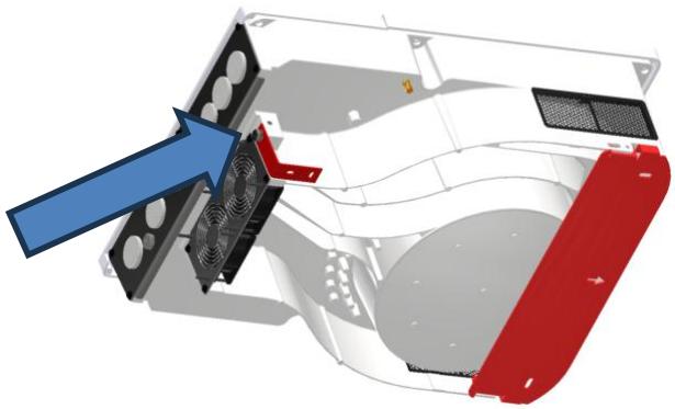
In vehicles (road or marine), or when the support undergoes significant vibrations, the next1 is to be mounted on anti-vibration elements. The next1 is not certified with specific norms for mobile application (vibrations,...).
- Hang the next 1 on the structure. Fix the ventilation grids.

- Connect the Wi-Fi antenna at the end (to avoid breaking it during mounting). Antenna may be mounted at factory.

- The device is installed. Open the bottom panel and proceed to electrical wiring as described in the chapter "WIRING".
4.4.2.1 Mounting of the nx-interface (option)
The nx-interface is an optional accessory of the next1 for customers that would like a physical screen installed near the inverter. It can be fixed on a wall or integrated on a control panel.

For the integration in a panel, the opening cut must be 122 x 190mm with a maximum radius of 1mm in the corners. The maximum thickness of the panel cannot exceed 4mm.


Mounting Instructions:
- Insert the device from the front into the cut-out of the panel and push it carefully until it is fully inserted
Insert the mounting elements (1) into the provided lateral T cut-outs (2) and push them sideways (3) so that they are locked.
- For the first mounting elements in a corner, tighten the fixing screw (4) until it presses on the plate. Tighten the fastening screws to a maximum torque of 0.2 Nm.

- Repeat procedure 3 for opposite mounting element.
- Repeat procedure 3 for remaining mounting elements.

Mounting elements and screw are provided
Observe the maximum tightening torque of the fastening screws of the mounting elements otherwise they may be damaged.
Tighten the fastening screws of the mounting elements to a maximum Torque of 0.2Nm.
See the Wiring chapter for cabling of communication. The nx-interface must be connected to the nx-bus communication bus.
5 WIRING
This chapter covers the wiring/cabling of the next1 installation before powering it!
5.1 GENERAL OVERVIEW
5.1.1 System block diagram
The general schematic diagram of the next1 is given below:

5.1.2 General recommendations
The connection of the next1 charger is an important step in the installation. The next1 is designed to be robust and is electronically protected against overloads, short-circuits, and overheating.
Be aware of the following general guidelines:
- The information, notes, recommendations, and diagrams reported in this manual are examples and must in any case be adapted to local installation rules. The installer is responsible for the conformity of the installation with the local standards in force.
- It may only be carried out by qualified professionals, aware of the rules and regulations in force.
- The cross-sections of the cables connected to their terminals must comply with local regulations even if indications are given in the following chapters.
- The installation materials such as cables, connectors, distribution boxes, fuses, etc. must be adapted and must be conform to the applicable laws and regulations, especially about fire hazards.
- All cables in use should be isolated with PVC, TFE, PTFE, FEP, neoprene or polyimide. Make sure that connections are correctly tightened and that each wire is connected at the right place.
The next1 falls within protection class I. It has a PE connection terminal. It is mandatory that a protective earth is connected to the AC-Source and/or AC-Loads PE terminals. An additional protective earth is located at the bottom of the unit and behind for the casing earthing.

The connection compartment of the next1 must remain permanently closed while the device is operating.
Before opening, check that all voltage sources of the system (AC, battery and PV) have been disconnected or switched off and wait for at least 2 minutes before opening the equipment. It is imperative to close the protection cover on the connection terminals after each service.
Before connecting or disconnecting the entry or exit cables AC-Source, AC-Loads and AC-Flex, the installer must be sure that there is no voltage present in the cables OR on the terminals.

Any unused cable entry on the device must be sealed to keep IP and prevent any intrusion. An intrusion of small animals in the unit may cause serious damages not covered by the warranty.
5.1.3 Connections overview
Open the connection compartment by removing the front cover:
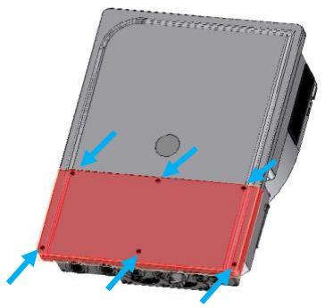
Connections overview:

| Denomination | Description | Comment |
| Protective earth connection terminal. | There are PE connections on AC connectors. The large bolts connections outside are for the case. | |
| + BAT | Positive pole battery connection terminals | Take care with the polarity of the battery! |
| - BAT | Negative battery pole connection terminals | |
| AC-Source | Connection terminals for the AC power supply (generator or grid) | Note: It is imperative that the PE terminal is connected. |
| AC-Loads | Connection terminals for the device output. | Note: It is imperative that the PE terminal is connected. |
| AC-Flex | Connection terminals which is configurable as second device output (loads) or as second AC source (for a second genset or grid). | The main choice between AC-Flex being a source or loads cannot be modified when the unit is running.Note: It is imperative that the PE terminal is connected. |
| Communication and I/O | There are different communication bus: Studer nx-bus, CANi for BMS, RS485i, Ethernet, USB.The sensor: nx-TempSensor: battery temperature sensorThe I/O: 2 auxiliary relays, 2 command inputs and 2 analog inputs. | The pinning is indicated on the male connector that can be removed. |
Details of I/O and communication:

5.1.4 Max permissible cable cross-sections, tightening torques
The maximum permissible cable cross-section for each connection is defined in the table below.
The tightening torque of different connection points should be checked regularly, especially in installations exposed to strong vibrations (mobile systems, vehicles, boats, ...). The table below states the recommended tightening torques for each connection:
| Connection | Cable max cross section | Torque |
| AC connector• AC-Source max 80Aac• AC-Loads Max 80Aac in transfer• AC-Flex Max 50Aac in transfer | Source/load: up dot 25 mm2Flex: up to 16 mm2Note: depending on the transfer current used! Breakers to choose according to planned max currents and cables. | 3.5Nm1.5Nm |
| Large Earthing PE connection on casing | Same as battery if it is grounded. | 9Nm |
| Battery DC screws | 2x 95 - 2x 50 | 9 Nm |
| Cover | 1.5Nm | |
| Panel mounting accessories on nx-interface (optional) | 0.2Nm |

An annual check of all the connection tightness is recommended. In mobile installations, the connection tightness should be checked more often.
5.2 CONNECTING THE AC (ALTERNATIVE CURRENT)

Dangerous AC may be present on the connection terminals. Make sure that the inverter is deactivated and that there is no AC or DC voltage present on the AC terminals before proceeding with the connection.
There are 3 AC connections:
- AC-Source: connection for the main AC source. A grid or a generator. This input has double security relays for disconnection according to safety and grid code requirements (like VDE-0126, EN50549-1 and others). In case of grid connection, always connect the grid to AC-Source. The transfer is rated 80A.
- AC-Loads: connection for the loads. The 230 V consumers must be connected on the "AC-Loads" connection terminals with the wire cross-section conforming to the standards regarding the rated current at the next1 output. The loads are supplied by the inverter from the battery in backup mode or directly from the grid with an internal relay (transfer).
- AC-Flex: this is a configurable connection to be connected to loads or to a genset. The choice of configuration is done at the setup of the system during the Wizard procedure. The AC-Flex configuration is fixed and cannot be changed anymore in operation for security reasons. The connection is rate 50A.
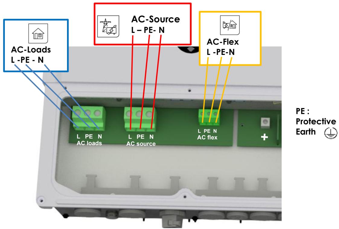
Refer to the general schematics (block diagram) at the beginning of this chapter for a better understanding.
The next1 terminals are marked in the following way:
N = neutral
L = lines (L1)
⊥ = protective earth (connected to the enclosure of the device).
Example of connection for AC loads:


Insulation tests
At commissioning of an electrical system, insulations tests are performed on the wiring (in some countries, depending on local regulation). It is performed by applying high voltages on the cables and measuring the leakage current. This must be done without the next1 in the loop. Overvoltage surge protections included in the next1 will invalidate the tests. Insulation between circuits and the ground is tested in factory for every next1 unit manufactured according to the device IEC/EN 62109 and IEC/EN 62477 safety standards.
5.2.1 Sizing of AC protective devices
The source must be connected to the input terminals marked "AC-Source" with sufficient wire cross-section, depending on the power output of the source, and protected by a protection device of the appropriate rating. In any case it must be maximum 80A.
For people safety, we recommend using residual current devices (RCD) for loads at the output of the next1. Take care of the earthing and neutral system for proper operation of the RCD. In any case, AC distribution must comply with the local standards and regulations, and generally, be realized through a distribution panel in an enclosure.
For cables protection, no downstream protective device is formally required if cross-sections of cable used for distribution satisfy regulatory requirements for the largest rated output current listed on the nameplate of the next1. The next1 is protected against overload and short-circuit and will stop in those cases. When connected to a source, the upstream protection must stop short-circuits currents from the grid/genset.
Due to the source assistance function (Smart-Boost), the current at the output of the device may be higher than the rated current of the inverter. It is the sum of the current supplied by the additional source and the current supplied by the inverter. In this case, the dimensioning of the output cables will be carried out by adding the current indicated on the protection device located on the upstream of the unit, to the nominal current of the inverter.
If circuit brakers (CB) are installed at the output, we recommend B curve devices. They will be sized at maximum to the highest value listed on the unit's nameplate or by the addition of the first value plus the value of the input protective device. (i.e. inverter current + input current). As an example, if the AC Source current is 20Aac per phase
and knowing that the current of the inverter is (6500/230)=28Aac per phase , the total current on the output would be 48Aac per phase.
In any case it must be chosen according to the cable size downstream.
smart boost 2.0

If the source assistance function (Smart-Boost) is not used; the size of the protection device for the AC-loads output will be established at a maximum value equal to the rated current of the inverter, or at the maximum value of the protection device at the input if that one exceeds the rated current of the inverter.
If the AC-source is not used the protective device will be sized equal or smaller than the smaller value indicated on the nameplate.
The next1 is intended to be supplied by alternative voltage sources such as the grid or a generator. Check that the rated voltage of the source corresponds to the rated voltage of the next1 model specified on the nameplate on the side of the next1.
5.2.2 AC Neutral and Earthing system
⊥ = protective earth (connected to the enclosure of the equipment).
The next1 is a unit with protection class I, which is intended for cabling in a grid type TT, TN-S or TNC-S. Its metal case must be earthed. The earthing of the neutral conductor is carried out at a sole installation point, upstream of the RCD circuit breaker (in domestic application, generally type A, 30 mAac). The PE cross section must be as big as the cross section of the line or neutral conductors.
The neutral insulation to the earth is checked by the device and errors will be raised by the next if the measurements doesn't correspond to the settings of the device.
In any case, the protective earth must be connected in accordance with local standards and regulations in force. The protective earth of the equipment must be connected at least to the protective earths of all the Class I equipment after and before the next 1 (equipotential connection).
5.2.2.1 Stationary installation and neutral continuity
In a stationary installation where the neutral is connected to the earth at a single installation point upstream of the next1, it is permissible to carry out a connection of the neutrals to preserve an unchanged earthing system downstream, independent of the operating mode of the next1. This is called “Solid Neutral”.
That can also be performed with the proper programming of the unit, controlling the internal earthing relay, but it may not be accepted for security reasons. Please check your local installation rules.
Example of solid neutral connection inside of the connection box:

Safety is guaranteed by the equipotential bonding and by any RCD circuit breakers placed downstream.
This connection can be done inside of the next1 with an internal relay and the proper programming. See the earthing relay configuration in the system configuration.

This solid neutral connection is not permitted if a socket is installed upstream of the next 1 (typically in mobile application).
It is also not permitted if the next1 is used for grid feeding as the grid-codes requires to disconnect both poles, L and N.
5.2.2.2 Mobile installation or installation connected to the grid via plug connector
When the input of the device is connected directly to the grid via a plug, the plug must remain accessible.

The connection (link) between the neutrals upstream and downstream of the next1 is not permitted in this configuration. Continuous neutral is not permitted.
In the absence of voltage at the input, the neutral and live are interrupted, thereby guaranteeing complete isolation and protection of the cabling upstream of the next 1 .
The earthing system downstream of the next1 is determined by the upstream earthing system when the grid is present. In the absence of the grid, the earthing system downstream of the inverter is in isolated mode. An automatic connection with an internal relay can be programmed with settings.
This connection type guarantees the optimal continuity for supplying the next 1 loads. The first isolation fault will not lead to an interruption in the supply.
If the installation requires the use of a permanent isolation controller this would have to be deactivated when the TT network is present at the next1 input.

All sockets and protection class I devices connected downstream of the next1 must be properly connected to the earth (earthed socket). The cabling rules above remain valid, including in installations, in all cases where the next1 input is connected to the grid via a plug connector.
5.3 CONNECTING THE BATTERY
The next1 is a device which DC connection is to be connected exclusively to a battery of the appropriate voltage of 48V, the voltage range is 38 to 68 V.

A battery voltage higher than 70V can cause important damage or destroy the equipment.
The recommended battery cable size is 70mm2. The maximal size is 95mm2 section.
The battery cables must also be as short as possible. The recommended cable cross-sections are valid for lengths less than 3 m. Beyond this length, it is strongly recommended to oversize the battery cables. The maximal battery cables length allowed is 10m.
Sufficiently tighten the clamps on the "battery" inputs.
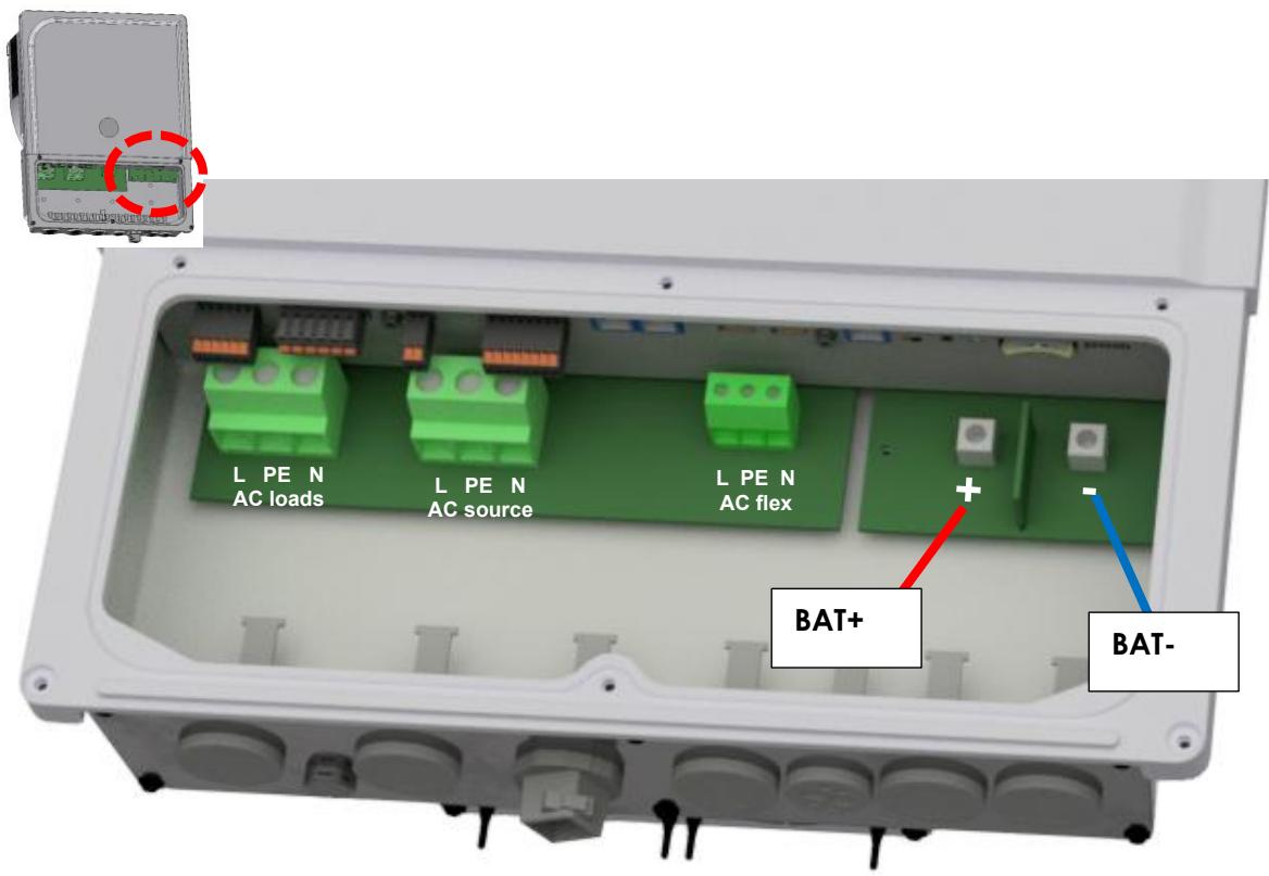
Start the connection on the next side first, without any voltage. Keep battery poles away/protected to prevent any unwanted contact with conducting parts.

Battery cables must always be protected by one of the following measures:
Have a protection and disconnection device (fuse, circuit breaker) on each pole or only on the pole not connected to earth.
The protection device must be rated according to the cable cross-section but must not exceed 1.25 x next1 maximum current.
It will be mounted as close as possible to the battery.
Per example for the nx1-6500-48 model, the maximum current is given with power of 6500W: 6500/48=135Adc with factor: 135x1.25=168Adc
In all cases check local regulation and normative
To avoid any further loss and protection redundancy, the next1 does not have an internal fuse.
In all cases check local regulation and normative.
Each next1 is connected directly to the battery through its own protective device (fuse or circuit breaker) and disconnection device. It should never be connected to the output of a DC voltage regulator like solar regulator, without having the battery as a buffer. All other consumers or sources are connected directly to the battery by their own protective and disconnection devices.

During the first start of the unit, it is necessary to check that the parameter values of the next1 are consistent with the recommendations of the battery manufacturer. Non-conforming values may be dangerous and/or seriously damage the batteries.
See the chapter about programming and set the proper values at initial commissioning (with wizard on nx-interface).
5.3.1 Earthing of battery
One of the two battery conductors can be earthed. This may be either the positive or the negative pole as the battery is galvanically isolated from AC. In all cases, the installation must be conformed to the local regulations and usage, or specific standards associated with the application.
In case of earthing, the earthing conductor cross-section must at least be equivalent to the cross-section of the battery conductor. The earthing of the equipment must also adhere to these regulations. For this case, use the additional earthing screws, which are located at the bottom of the device under the AC cabling glands and under the device.

All the other earthing systems (earthing by means of a protection device, impedance, without earthing or earthed at battery positive pole) require the whole battery circuit to be protected against electric shocks. Any accidental contact with the conductive parts of the battery circuit is to be avoided by providing a Class II protection level.
5.3.2 Battery with communicating BMS: CAN connection
The next1 uses a CAN Bus to communicate with the BMS (Battery Monitoring System) of a lithium battery. Lithium batteries are more complex to handle compared to lead acid batteries. A BMS is responsible of cell monitoring and battery safety. The BMS knows the status of each cell, and it computes maximum charging/discharging currents and maximum/minimum target voltages. These values must be respected when the installation is working and BMS communicates to inverter/chargers the proper setpoints for proper operation.
The next1 has several CAN protocols implemented for communication with different battery management systems of different battery brands. Compatible batteries are (main brands here):
• *BYD
• *CEGASA
• *Pylontech
• *Sunlight
• *WECO
• *ZYC
*tested and validated by Studer.
And others with compatibility tested by the manufacturer: Archimede Energia
Autarctech, BlueNova, BMZ, BSLBATT, Cosun, Discover, Dyness, Enershare, Fortress Power, Freedom Won, GS-HUB, IPS, Leclanché, LG Chem, Midac, Omega Power, Pallas, PowerTech, Pytes, Solar MD, Soltaro, Super-B, Surya Utama Putra, Tesvolt, Turbo Energy, Twice, UZ Battery, Vision Mechatronics, Zetara, Zruipower,...
And standard BMS:
- Solarni Panely
- REC Q
- Orion
See the Studer-Innotec website for the up-to-date list of compatible batteries, brand and models: https://technext3.studer-innotec.com/compatibility
Check for updates of the next1 software to have the latest communication protocol.
Beware of the pinning order (CANH, CANL, GND) on the connector and see the instructions of the BMS manufacturer carefully.
As example here is the pinning for the CIA-303-1 : (Warning, a lot of battery manufacturer have different pinning!)


That must be wired/screwed with the provided connector:


Communication for compatible devices
Pinning left to right is:
-
RS-SH Shield
-
RS-A / D-
-
RS-B / D+
-
RS-GND
-
CAN-SH Shield
-
CAN-L Low
-
CAN-H High
-
CAN-GND
Technical note on CAN BMS bus: termination impedances are electronically controlled by the next1 and are set by default. This is automatically managed.
5.3.3 Battery temperature sensor connection (nx-tempSensor in option)
The operating voltages for lead batteries vary depending on the temperature. A temperature sensor is available in option to correct the battery voltage and guarantee an optimum charge in function of battery temperature.
The temperature range of the sensor is from -25°C to 70°C. The default temperature compensation for lead acid batteries when a sensor is plugged is -3mV/°C/cell compared to 25°C. For a 48V battery this is 72mV/°C. See the configuration section of this manual for modification of the temperature coefficients. A warning is raised at 40°C and error is raised at 55°C; those thresholds can be modified.
The temperature sensor nx-tempSensor is supplied with a 10m cable and the proper male connector beside. The connection has no polarity and can be done in one or the other direction without preference. The sensor should be placed as close as possible of the battery.

The temperature sensor is automatically recognised, and the correction of the voltage thresholds applied immediately in case of non-communicating battery. If a communicating battery is used the temperature measured by this sensor is not taken into account as the temperature is directly given by the BMS. The nx-tempSensor temperature is recorded in the datalog.
5.3.4 Notes on batteries
5.3.4.1 Dimensioning the battery
The battery bank is dimensioned depending on the user's daily energy consumption and the number of days of autonomy required. It is sized also in function of the wanted daily Depth Of Discharge (DOD).
The dimensioning of the battery must also consider the power and the type of loads that are connected to the inverter. As rule of thumb, the maximum power of a lead acid battery is given with the capacity divided by five (C/5), in that case if all the power of the next1 is wanted (6kW), the capacity of the battery should be at least6500/48*5=677 Ah.
For lithium, see the maximum power defined by the manufacturer as lithium batteries are generally rated with a much higher current (C/3 or even up to 1C).
Consider the surge power of loads, for example for motor starting and the overload capacity of the inverter to dimension your battery system.
Lead batteries are usually available in 2Vdc, 6Vdc or 12Vdc blocks. To get the correct operating voltage for the next 1 , several batteries must be connected in series. The capacity of the batteries can be increased using a parallel connection of several battery strings.

Strictly conform to the manufacturer's instructions for parallel connections of batteries for battery bank design, especially with lithium batteries.
5.3.4.2 Precautions when using batteries
The batteries should only be chosen, dimensioned, and installed by qualified personnel. Lead-acid batteries with liquid or gelled electrolyte produce a highly explosive gas during normal use. Other special types of batteries present similar risks. Avoid source of sparks or fire in the immediate vicinity of the batteries. The batteries must be kept in a well-ventilated place and installed to avoid accidental short-circuits when connecting.
Never try to charge frozen batteries. When working with batteries, a second person is required to give assistance in case of problems.
Fresh water and soap must be kept close at hand to allow adequate and immediate washing of the skin or eyes affected by accidental contact with the battery acid. In the event of accidental contact of the eyes with acid, they must be washed carefully with cold water for 15 minutes. Then immediately consult a doctor.
Care is required when working close to the batteries with metal tools. Tools such as screwdrivers, open-ended spanners, etc., may cause short circuits. Sparks created by short-circuits may cause the battery to explode. Therefore, these kinds of tools must always have isolated handles and never be placed on top of a battery. When working with the batteries, all metal jewellery such as rings, watches with a metal bracelet, earrings, etc., must be taken off. The current supplied by the batteries during a short circuit is sufficiently powerful to melt the metal and cause severe burns.
Batteries at the end of their life cycle should be recycled in accordance with directives from the responsible local authorities or the battery supplier. The batteries should never be thrown into fire as they may explode. Under no circumstances should you try to take apart or dismount the battery, as they contain toxic and polluting materials. For ungrounded battery systems, always check that they are not inadvertently grounded before starting to work on the batteries.
Always carefully follow the instructions of the battery manufacturer.
5.4 LIGHTNING PROTECTION
According to the installation site, it is highly recommended to develop a protection strategy for your installation. The strategies depend on various factors specific to each site; we recommend therefore a professional approach to this issue. Contact a specialist on surge protective strategies to check how you can best protect your system in all inputs/outputs (AC and DC).
The next1 has internal protections against lightning by means of surge protection devices. These devices have an energy dissipation capacity limited to 3,5kA (8x20 µ s) which guarantees a certain protection level but are not a total protection against lightning. Furthermore, these protections are for single use. Therefore, in the event of a lightning strike where these surge protections are hit, you'll have to send the unit for repair. They cannot be replaced nor repaired on site.

Damages due to lightning often result in significant costs (full replacing of the printed circuit board, PCB) and are not covered by Studer Innotec's warranty.
5.5 CONNECTING THE COMMUNICATIONS CABLES
5.5.1 Connecting the Studer communications cables
The Studer nx communication bus is used to interconnect next1 inverters in the case of a multi-unit application or to connect the nx-interface.
It uses a proprietary protocol of Studer-Innotec and must not be connected to any other devices.
The cables for Studer nx bus are straight ethernet of category 5 exclusively with 26AWG wire size (power supply through cable).

Communication and I/O

Studer nx bus
They are provided by Studer, or you can buy your own if it follows these requirements. The total length of the communication bus cable between all units must not exceed 75 m. For long distance it is advised to use shielded cables (STP) and consider AWG24.
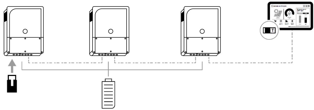
In this network, all parties in the network are connected in daisy chain. Both ends of the chain must be terminated with an impedance. For this, use the termination plug where there is no other communication cable connected.

With the use of other accessories (like nx-interface) that have a switch for the termination, the switch for the communication bus termination remains in position T (terminated) except when both connectors are in use. In this case, and only in this case, it must be placed in the O (open) position. If one of the two connectors is not in use, the termination switch will be in position T.

A single connection is used : T or use terminator
Both connections are used : O
...
Both connections are used : O
A single connection is used : T or use terminator

These connectors must be used only to connect a compatible next1 accessory, excluding any other type of connection such as LAN, Ethernet, ISDN, etc.
The next1 nx-communication is not compatible with other Studer communication. It is not compatible with Xtender devices, and it must never be directly connected together.
Any unauthorized connections could cause the destruction of the devices.
A standard configuration with 3 next1

A configuration with 3 nx1 and one nx-interface using the termination plug:

It is always possible to use the sliding switch on the nx-interface on T, but in this case don't double the termination with the RJ termination.

When connecting one device with other compatible devices using the same communication bus, it is highly recommended to make a software update of all components in the system to guarantee their proper compatibility/functionalities.
If the devices are connected to internet, this is possible to perform online update, else download the latest software version from our website: www.studer-innotec.com and copy it to an USB key for an local update. See the nextOS manual for details about updates.
5.5.2 Connection of the nx-interface (option)
The nx-interface must be connected to the Studer nx-bus. The nx-interface is powered through the cable, its type must be ethernet of category 5 with 24AWG wire size (power supply through cable).

The state of the Studer nx bus termination on the nx-interface can be seen on the screen, this is only for the connectors situated on the nx-interface.
The LAN cable can be plugged on the nx-interface instead of inside of the next 1.
The RS485i in the nx-interface is used for Modbus RTU.
Note: the CANi connector on the nx-interface is unused for the moment. This must not be used for battery communication.
5.5.3 Connection to Internet
5.5.3.1 Wired connection
The connection to your LAN router and then internet is done exclusively on the Ethernet port of the next1 (or the Ethernet port of the nx-interface in option).

Differentiate carefully the ethernet connector on the right side of the nx-bus connector on the left side.
In remote area, you must find your own GSM 3G/4G/5G router (not provided) and connect to it with the ethernet cable. Studer-Innotec is not responsible for the proper operation of those devices and of your internet connection.
5.5.3.2 Wi-Fi connection
The next1 is supplied with a Wi-Fi antenna and a local access point is enabled by default.
To connect to an existing Wi-Fi, the credentials (Wi-Fi name and password) must be given. Please follow the instruction of the first commissioning procedure for this.

5.6 WIRING AUXILIARY I/O
Auxiliary I/Os are all located inside of the next1.
Communication and I/O connections:

See corresponding chapter for detailed wiring and protocol in use.
| Denomination | Description | Comment |
| Command inputs | Two digital inputs to indicate external changes to the unit and two analog inputs for voltage measurements (for sensors). They can be used t in the range 10-60V | Pinning left to right is1. +12V2. IN1 Digital3. IN2 Digital4. IN3 Analog5. IN4 Analog6. GND IN |
| AUX1 and AUX2 CONTACT | Programmable dry contacts. 16A/230VC: CommonNC: Normally ClosedNO: Normally Open | Take care not to exceed the admissible loads.Pinning left to right is1. NO12. C13. NC14. NO25. C26. NC2 |
| nx-tempSensor | Connector for the battery temperature sensor. | Only connect the original Studer nx-tempSensor. |
| Com ISO:RS485 and CAN BMS | Isolated communication, this connector has two communications, the RS485 for Modbus and the CAN for BMS of lithium batteries | Pinning left to right is1. RS-SH2. RS A /D-3. RS B /D+4. RS-GND5. CAN-SH6. CAN-L7. CAN-H8. CAN-GND |
| CAN BMS | Isolated CAN bus for communicating BMS of lithium batteries | Only for CAN BMS! |
| RS-485i | Communication to accessories | Only for official Studer accessories |
| Studer nx-bus | Two connectors for internal communication between Studer next devices such as the nx-interface or other next units | Only nx-bus compatible device can be connected. The connection of any other device (LAN routers, can-to-can interfaces, etc.) may damage the device. See chapter 4.6. The nx-bus is not compatible with other communication bus from Studer (for example Xtender bus). |
| USB | For manual update and storage of datalog files | One usb key is provided by default with the nx1 for local and permanent storage of datalog. This USB drive is meant to always stay connected to one USB port of the device. |
| Ethernet connection | Plug to your router for wired internet access to your next1 |
5.6.1 Command inputs: digital and analog Inputs
There are 4 inputs that can be used as digital or analog inputs!
Pinning left to right is
- +12V IN
- IN1 Digital
- IN2 Digital
- IN3 Analog
- IN4 Analog
- GND IN (reference for digital inputs only)

The 6 poles male connector is supplied with the nx1. Double check the correct pinning before plugging the connector on the nx1.

Digital inputs (IN1 and IN2) that can be active with a 10 to 60Vdc voltage to the return reference. A +12Vdc supply is available on the connector for the use of dry contacts. Don't use it for other purpose than the activation of input entries. The current is limited. External 12Vdc can be activated/deactivate with settings in the device menu (on nx-interface).

For activation with a dry contact:
Supply voltage with +12Vdc, go to the contact and come back to the wanted input (in1/2)
For activation with an external source: a potential of 10dc to 60Vdc must be applied between an input and the return.
Entry impedance is 10kOhm
The analog inputs IN3 and IN4 also have a range up to 60V max.
The gain can be controlled by software by giving the 100% voltage. Per example for signal varying 0 to 24V with a range value given correctly in software with 24V, an 6V measurement will be recorded as 0.25 (25% of the range).
For a good resolution, the measured voltage range should be 10V and above.


Voltages to measure 60 Vdc max
For analog measurement of an external voltage, max value is 60V.
Entry impedance is 140kOhm
5.6.2 Auxiliary relays
There are two reversing dry contacts available in the nx1 unit, both are potential-free.

Various settings are available to give activation conditions to each contact. To program functions to these contacts, please refer to the nextOS manual about the configuration of the next1 and the section about the auxiliary contact in this manual.
Wire the C (common) in any case and the second position in function of your application and your settings. In relax state, there is a contact between C and NC (Normally Closed). An activation gives contact between C and NO (Normally Open) and disconnect C and NC. The representation of the contact near the terminals corresponds to the status of the contact when not activated.
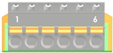

Male connectors are provided with the nx1. The admissible currents and voltages for these contacts are 16 A: 250 Vac/24Vdc or 3 A: 50 Vdc max. The connector has a male and female parts.

Doublecheck the correct pinning when plugging the connector on the nx1.
5.6.3 USB ports
There are two USB ports inside of the next1. One is always used for an USB memory drive that:
• Stores the daily csv files
• Is used for device update (if not connected to internet)
5.6.4 Isolated communication: RS485i and CAN BMS


Communication for compatible devices
Pinning left to right is:
- RS-SH Shield
- RS-A / D-
- RS-B / D+
- RS-GND
- CAN-SH Shield
- CAN-L Low
- CAN-H High
- CAN-GND
The RS-485i connection is for official compatible accessories for the next1 only.
The compatible accessories are:
• Xcom485i-nx for communication with variotrack and Variostring in the system.
- The energy meter Powermeter for house introduction measurement.
For a general Modbus RTU to read values and change settings on the next1, you need an nx-interface in option. The Modbus TCP is included with the LAN connection (See the application note on https://technext3.studer-innotec.com/modbus-next and the document Modbus appendix for the full list of registers.).
The CAN is exclusively for connection to the battery BMS.
Beware of the pinning order (CANH, CANL, GND) on the connector, see instructions of the BMS manufacturer carefully. See more details in the battery chapter earlier.
5.7 MULTI-UNIT CONFIGURATIONS
Up to three next1 units may be used together in parallel. They are connected on the same battery bank or on separate battery banks to create a high-power inverter-charger system:
- In parallel:
- Two units of next1 creating a 13kVA inverter with an 80A transfer (18.4kVA).
• In split phase configuration:
- Two units of next1 creating a 13kVA split phase inverter with an 80A transfer (36.8kVA).
• In three phased configuration:
- Three units of next1creating a 19.5kVA three phase inverter with an 80A transfer (55.6kVA).
With two units per phase 39kVA three phase inverter with an 80A transfer (55.6kVA).

The following points must be followed:
- In multi-unit systems, the next1 units communicate via the “Studer nx communication bus”. This is mandatory for proper synchronization of units that must absolutely work together. If communication is lost, all the system stops.
- Units should be close to each other (in the same room).
- Each device must have the same software version, updates can be downloaded automatically by the device or are available on the Studer website https://studer-innotec.com/downloads/
- All elements must be connected and powered before the initial configuration. All elements must be clearly identified during the configuration process with the wizard.
- In multi-unit systems, only one of the communication gateways (internal to the nx1) must be used for connectivity (internet, wifi, USB, ...).
- Use only one nx-interface per system. The system will not work properly with multiple nx-interface communicating at the same time on the bus.
- Reconfiguration of the system with the wizard is mandatory when you add new elements to the system.
- All the AC-Loads connections of each of the next 1 units of a system must be connected in parallel, for each respective phase (through a distribution panel for example).
- All the AC-Source and AC-Flex ports must be kept separate. The purpose of each port is chosen during the wizard.
- All the AC-Flex ports configured as Flex Load must be kept separated. The different AC-Flex can be programmed separately.
- Only one AC-Source connection for the grid (if available), and one AC-Source or AC-Flex for the genset (if available) will be used in a system. There is an identification process during the configuration of the system with the nextOS wizard. That means the maximum transfer is 80A. That is 80x230=18.4 kVA in single phase and 80x230x3=55.2 kVA in three phased.
- The three next1 work as one in a system, except for:
- The AC-Flex as load can be programmed independently, they must not be wired together.
- The AUX relays and CMD IN are independent.
- The compatibility is only between the next1 units. Don't mix with other Studer-Innotec products like the Xtender. This will not work and probably damage the devices.
5.7.1 Parrallelling AC in multi-unit
In parallel, all AC-Loads are connected together, all AC-Load L (live) are together and all AC-Loads N (neutral).
There is maximum one grid and one genset connection in a system. The different AC-Source ports of each of the next1 units must be kept separated.
Below is the example for the standard grid-connected case for three units:

During the wizard, the proper unit that is physically connected to the grid/genset must be selected.
When using a genset at the same time as the grid, it is advised to use the AC-Source of the second inverter. One is connected to the grid and one to the genset.
That way all AC-Flex are available for flexible loads.

5.7.1.1 Threephased connection
In three-phased configuration, all AC-Loads L (live) are separated but the AC-Loads N (neutral) are common. The same applies to the AC-Flex used as load: the AC-Flex are separated.
In three-phased system it is advised to use a common battery, as the load balance between the phases is not always optimal.

5.7.1.2 Splitphase connection
Splitphase is used typically with 120Vac models. It allows to have 2x 120Vac and 240Vac voltage.
In split-phase configuration, all AC-Loads L (live) are separated but the AC-Loads N (neutral) are common.
In splitphase system it is advised to use a common battery, as the load balance between the phases is not always optimal.

5.7.2 Batteries in multi-units
It is allowed to have one common battery or multiple batteries. With one common battery, the CAN-BMS is linked to one next only. It must be identified and configured during the wizard process.

Don't mix the communication bus of the batteries. One next1 is connected to one battery power (DC+/-) and its associated BMS (CAN) at the same time.
The communication bus to the battery BMS, the battery DC connection and the nx-bus are isolated from each other. There is no special requirement for the connections of multiple batteries. Per example, the minus (or plus) can be common, but this is not required. Each pole can be grounded or left floating. The installer is not constrained by the next 1 but must respect the official installation rules of his country for his type of application.
With lead acid batteries, each next must have its own temperature sensor.
In multi-unit systems, the charge/discharge current of each unit is automatically chosen by the PFD (Power Flow Dispatcher, which is a patented control algorithm). You just need to specify the characteristics of each battery during the wizard process.
The PFD algorithm computes the balancing using these main rules :
- The charge/discharge is distributed proportionally to each battery capacity.
- The charge/discharge limits are used independently.
- Each SOC is managed independently, and each limit is respected (e.g. you can program different behavior for different packs of batteries)
5.7.3 Extension of an existing installation
It is possible to extend an existing installation by adding one or several similar next1 units in parallel. The software compatibility of the new units is mandatory.

Equipment belonging to the same system must be operating with the same software version. Download the latest software version from the Studer's website and update the software for all units of the system independently before commissioning.
5.8 SPECIAL CONFIGURATIONS
Some special configurations are possible with the next1, especially with integration of solar converters in the system.
5.8.1 AC-solar: connection of solar inverter in AC-coupling
A grid inverter from a third-party manufacturer can be integrated into the system. It can be connected downstream. With single phase next1, it should be single phase grid inverter.
The recommendation is to connect it to the AC-Flex connection as this will allow separate monitoring from the load.
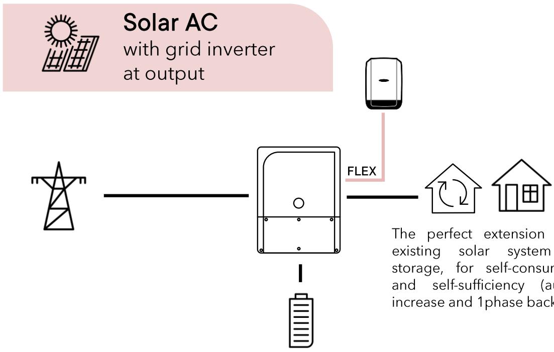
If this configuration is used, this must be indicated during the wizard process in order to allow power to flow to the AC-Flex and be counted as solar in the monitoring.
5.8.1.1 Operation with a power meter
In that case, a smart power meter is installed at the electrical main entry point of the building. This measurement unit allows the next1 device to know the balance of consumption-production and then to decide when to charge or discharge. In this configuration, a solar inverter (AC-solar) or loads can be connected upstream. Only the allowed power meter supplied as accessory by Studer-Innotec must be installed. It must be connected to the next1 RS485i port using the MODBUS RTU communication cable.
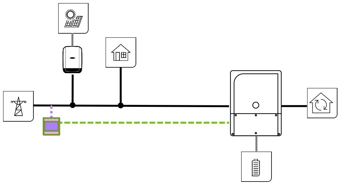
The presence of the external power meter must be configured during the commissioning wizard.
The compatible power meters are:
- Threephased direct connection: EM540 DIN AV2 3X S1 X
- Threephased with CT: EM530 DIN AV5 3X S1 X
- Current transformer: CTA-5X. Choose the needed current (100A, 150A,... 600A)
- Single phase direct connection: EM511 DINAV8 1X S1 X

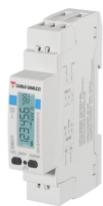

See nextOS manual for more details.
5.8.2 DC-solar: integration of Studer solar chargers Vario in the system
Compatibility with the existing solar charger of Studer is possible with a communication bridge
Compatible elements are:
• Variostring VS-70 and VS-120
• Variotrack VT-40-145, VT-65-175 and VT80-175
These elements can be connected to the next system exclusively with a communication bridge xcom485i. Never connect directly the solar chargers to the next1 (or next3). The Xtender communication bus and the Next communication bus are not compatible.
Up to 5 chargers can be connected in a system.

The presence of the external solar chargers must be configured during the commissioning wizard. The physical wiring of a MODBUS communication cable is done with the Xcom-485i.


The next1 nx-communication is not compatible with other Studer communication. It is not compatible with Xtender devices, and it must never be directly connected together. Never use Studer-can/nx-can to wire the solar chargers. Use exclusively the RS485 connection.
5.8.2.1 Xcom485i-nx configuration
The Xcom485i must be configured according to the following picture and with a software version later than 1.6.96 (R704).

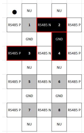
This is for a connection to the next1:

Order an xcom485i-nx kit with number [119017]:
- Already configured with proper software.
• 2 Cables provided (2x2m) - Update of Vario and Xcom 485i with SD card and RCC!
5.8.3 Minigrids with AC-coupling
A minigrid is a larger system with a distribution network that supplies many consumers. A minigrid can be created with the nx1 with one to 9 units plus the addition of AC-solar.

This allows systems up to 9x6.5kVA = 58.5kVA and the equivalent of AC-coupling for a total of 117kW.
6 POWER-UP OF THE EQUIPMENT

There are dangerous energy sources inside the cable compartment. It is imperative that the closing cover for the connection compartment is installed and screwed tight before energizing the installation!
The powering of the next1 starts with the battery. The unit cannot be powered by AC without battery. When supplying the 48Vdc voltage on the battery connection, the next1 device beeps and all lights turn on for a few seconds. After that, your next1 installation is in the following state:
- The next1 is OFF (no AC voltage on the AC load connector)
- The red LED is permanently light on, because the next 1 is OFF
• The voltage production on Ac Load is disabled - The connection to AC-Source is disabled (grid/genset symbol is light off)
• The AC-Flex is disabled (flex light off) - If any, the nx-interface starts its boot process and takes about 30 seconds to be ready.
- The internal gateway starts his boot process. It takes about 30 seconds until the WIFI LED lights up and indicates it is ready to operate.
6.1 INITIAL CONFIGURATION REQUIRED
A next1 installation requires an initial configuration with the wizard. This must be done using a smartphone or computer (via the web interface) or using the nx-interface. Make sure to have this device with you for the first commissioning.
The next1 will not start its operation without this first configuration.
6.2 FRONT PANEL BUTTON
In the middle of the front panel is a button with the following functions available depending on how long the button is pressed:
- Impulse push: clear error(s) if any, stop beeping
- Short: 1 second < push < 3 seconds: ON/OFF of next1 and all its functions. Signalled by one beep after 1 second.
- Long : 3 seconds < push < 10 seconds: the button has no effect when you release it, this is for the case when you pressed long by mistake. Signalled by two beeps after 3 second.
- Longer: press >10 seconds: reset all devices. Signalled by 5 beeps after 10 seconds.
You can hear the device beeping after \~1sec, \~3sec and \~10sec and you can release the button to achieve the associated function at that moment. The front panel button can be deactivated/activated via nextOS (but it is not recommended).
To power ON the next1 and all its functions: push the front panel button until you hear the first beep (or use the ON/OFF function of the nx-interface or web interface). After this, your next1 installation is in the following state (please note that it takes \~5sec to start all converters):
• The next1 inverter is ON.
- The “!” red LED is permanently off, because the next1 is now ON
• The battery is connected (battery symbol is light on)
• The voltage is provided to Ac-Loads (house symbol is light on)
- The connection to Ac Source is enabled (grid/genset symbol is light off or light on depending on your configuration)
- The Ac Flex is enabled (grid/genset and house symbols are light off or light on depending on your configuration)
If the system requires configuration or setting modifications, carry them out immediately. These must be modified by means of the remote control nx-interface or the web interface (smartphone/laptop).
Please note that powering from the grid without battery is not possible. If there is no battery connected, the next1 will not start and shows no indications.
6.3 FRONT PANEL LED INDICATOR
The front panel has the necessary information to understand basically the state of the next 1 with the LED lights.

The table hereunder describes the information or type of error according to the number of flashes of an LED indicator.
| N° | Indicator | blinking | Explanation |
| 1 | Central circle indicator (white light) | permanently OFF | next1 is OFF |
| permanently ON | next1 is ON | ||
| 1x | standby / load search mode | ||
| 2x | waiting to restart: warning voltage can come back. | ||
| 2 | Central circle indicator (red light) | permanently OFF | no error, at least one converter in the system is turned on |
| permanently ON | next1 is OFF | ||
| 1x | battery discharge is stopped due to low battery voltage | ||
| 2x | overload due to either a short-circuit or too high load for the inverter | ||
| 3x | decrease of the inverter power output due to a too high internal temperature. This may be due to overload of the device, too high ambient temperature or obstructed ventilation. | ||
| 4x | other warning(s) or error(s) (please see the nx-interface for details in warning messages) | ||
| 3 | AC-Source indicator | permanently OFF | source is deactivated, or not present |
| permanently ON | source is connected and working properly | ||
| 1x | source is present but next1 is in waiting procedure for connection | ||
| 2x | exceeding the source maximum allowed power | ||
| 3x | phases order is incorrect, or one phase is missing | ||
| 4x | source has other warning(s) or error(s) (please see the nx-interface for details) | ||
| 4a | AC-Flex used as a source indicator | permanently OFF | source is deactivated, or not present |
| permanently ON | source is connected and working properly | ||
| 1x | source is present but next1 is in waiting procedure for connection | ||
| 2x | exceeding the source maximum allowed power | ||
| 3x | phases order is incorrect, or one phase is missing | ||
| 4x | AC-Flex has other warning(s) or error(s) (please see the nx-interface for details) | ||
| 4b | AC-Flex used as a load indicator | permanently OFF | loads are not powered |
| permanently ON | loads are properly powered | ||
| 1x | standby / load search mode | ||
| 2x | AC-Flex has other warning(s) or error(s) (please see the nx-interface for details) | ||
| 5 | Connectivity indicator WIFI / Ethernet | permanently OFF | No connectivity. The internal gateway is turned off or starting up |
| permanently ON | Wi-Fi or ethernet connectivity. Access Point Wi-Fi accessible (if not disabled by user) | ||
| 1x | no available connection (connection lost). Check your network, router, credential. Access Point network is disabled by user (Please reset connectivity using internal button if you want it | ||
| 2x | Connection is only available using Access Point Wi-Fi network | ||
| 3x | No valid connectivity is present on internal gateway. Please contact Studer support (Antenna dongle disconnected, hardware problem, ...) |
Special cases:
- If there is absolutely no light on any of the LEDs, the next is completely without power (battery disconnected) or there is a problem with the display of LEDs.
- When powering up the next1 with the battery, all LEDs blink once during the start check.
- All LEDs can blink at the same time in an identification procedure (from nextOS). It is possible to identify the devices in multi-unit system that way:

6.4 BEEP INDICATOR (BUZZER)
The sound produced by the next1 buzzer uses the same beep sequence as the central “!” red light flashing sequence.
This buzzer can be deactivated/activated with the nx-interface or the web interface.

7 USER INTERFACE: THE EMBEDDED WEB INTERFACE
The end-user can interact with the next3/next1 with different interfaces:
• A local web interface on smartphone/tablet/computer
• The touchscreen nx-interface (in option)
- When connected to the web:
- on the monitoring portal
- with the iOS/Android APP on a smartphone/tablet.
It is also possible to communicate with the next3/next1 with machine to machine via communications through Web API to the portal and MODBUS RTU or TCP.
There is a dedicated manual about nextOS which is the general software environment and the way to interact with the next range. The minimal information for the first commissioning is given here below and is about the web interface provided by the embedded webserver in the gateway of the nx1.

See the nextOS manual for details about the interfaces and programming!
Find it on:
https://technext3.studer-innotec.com/nextos
and pdf on: https://studer-innotec.com/downloads/
The embedded communication gateway of the next1 and its webserver allows to:
- Visualize the state of the next1 system, present and past values, including the log of the events that happened to the system.
- Configure the devices: The next1 configuration can be modified by the installer/user at commissioning in order to adapt the equipment to the energy system in the best possible way. The normal process to configure the next1 is the use of the “Configuration Wizard” at the commissioning. This is a step-by-step procedure that helps you to configure the system in a simple way. This avoid mistakes and is the preferred way to configure the device. Individual settings are also accessible for each part of the next1. The factory values of these settings are reported in the table at the end of this manual.
- Record monitoring data: To analyse what happened in the energy system, the next1 stores measurements data in its internal memory and on a USB memory stick for later analysis (CSV files).
- Be connected: The next 1 can be connected to the internet and the Studer monitoring portal. The monitoring data are available in the Studer web portal user account(https://portal.studer-innotec.com). An app “Studer Monitoring” for iOS/Android is available for a simple monitoring.

7.1 FIRST COMMISSIONING WITH THE WEB INTERFACE
After installation and powering the unit with the batteries, wait about 30 seconds until the Wi-Fi LED turns on.

The nx1 is delivered with its Wi-Fi in hotspot as default mode and you can connect to this by selecting the Wi-Fi in your phone/table/computer. This can be done by scanning the QR-code on the side of the unit or by selecting manually the Wi-Fi with the name starting with studer-next-. All connection information is found on the label on the side of the unit next to the QR-code.

The web interface is available at address https://studer.local (or https://192.168.100.1). You can type this address in the address bar of your favorite web browser.

A security message is displayed by your browser. This is normal as a page cannot have a validated certificate in hotspot mode, when not connected to Internet. Go into the details and accept the connection to the page.

To login, you can use the "QR Code" button then scan the same QR-code used for Wi-Fi connection. Otherwise, you can manually enter the login credentials, which are also written on the label on the side of the unit next to the QR-code.

The access to the web interface can be done with the Studer Monitoring App. This is the preferred way as it will avoid the security question.
Once you have installed this app on your smartphone/tablet, you will have the possibility to login with your studer portal account (or create one if you have none). This step is optional, but logging in is recommended as it will greatly simplify
Download Studer Monitoring APP



the integration of your new device on the Studer portal for monitoring purposes.
Then you can start your device configuration by using the “Start new next setup” functionality from the top-left menu and by scanning the QR-code on the side of your device when asked.

Then the configuration wizard as described below can be used
When ready, the inverter can be turned on by pressing the button 2 seconds.

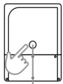

on
230V
7.1.1 Minimal commissionning information
The basic elements you must know about your system before commissioning to answer the questions are:
AC-grid
• What is your grid connection?
What is the capacity of the electrical source, typically given by the breaker size, for example 16A/25A/32/40A on each phase is common in houses.
What is the grid-code to use? Generally, it is a single choice per country, but it may be many (per example there is Australia A, B or C)
AC-genset
- Do you have a genset in the system? If Yes
■ Is it a single phase or three phased?
■ What is the rated current per phase going to the next1 inverter.
- Per example an 18kVA threephased genset that is able to give 15kW: 15000/3/230=21.74 A → rounded down to 21A. Take into account deratings due to ambient temperature, altitude, ...
- It is often given by the breaker size going to the inverter and limiting the current.
Batteries
• What batteries do you have?
○ Type: lithium, lead acid?
o Communicating? With which protocol? Be sure it is compatible before commissioning (and buying)
○ Number of battery modules and capacity of one battery module and in Ah (per example an 5kWh battery at with 50V is 5000/500=100Ah)
Internet connection
- If the device will be connected to internet with Wi-Fi, have the wifi name, and login ready to enter them at commissioning (that can be done later, if not available).
7.1.2 Configuration Wizard
At first commissioning you'll have the configuration Wizard running by default.
The configuration Wizard is a list of questions asked one after another about the system. Simply follow the instructions. All points are fully described in the nextOS manual.
Here a point of the wizard specific to the next1 inverter is commented, other are standard to the nextOS:


The next1 is a single-phase inverter. When there are multiple units, it can be connected in three phased or parallel configuration. That configuration is chosen by assigning the inverter to the phases during the wizard.
After the wizard, use the main menu to go to all the wanted screens

7.1.3 Use of wifi client at the end of the process
The Wi-Fi configuration is entered during the wizard process. If information is not available, it is possible to modify it later in the monitoring menu → internet connection →Wi-Fi page →select the Wi-Fi interface mode as Wireless client. Connection to the internet for monitoring is mandatory to be able to see it on the Studer portal and App).
7.1.4 DNS troubleshooting: "page not found"
Some internet routers do not accept the alias URL address https://studer.local to communicate with a local device 1 . The real IP address should be used instead. If your gateway is an nx-interface, you can easily find the IP address in the Monitoring menu, by clicking on the Internet connection configuration button and reading the IP address(es) of your network connection(s).
For the next1 internal gateway, the following steps can be taken to solve the problem:
- First you need to make sure that the mobile device or computer you are using is connected to the same network as your next device. It is important that both devices are connected to
the same router in order to communicate without problems.
- Use the Studer Monitoring iOS/android application, that has a dedicated button for accessing nextOS when your mobile device or computer is on the same local network as your next device.
-
Find the direct address on the portal: if the installation is connected to internet through ethernet or Wi-Fi, then you can read the IP address on the monitoring portal https://portal.studer-innotec.com by logging in and opening the Remote Control view for your installation. Then you can access these two properties for reading the IP address(es):
-
ID 20.1.18.4 for ethernet IP
○ ID 20.1.19.4 for Wi-Fi IP
- If the problem is encountered when your mobile device or PC is connected to the hotspot/access point Wi-Fi network, then use the default IP address: 192.168.100.1
• Try multiple times, some devices only try once.
- Use an IP scanner tool, and try to connect to all valid IP addresses discovered on your network
- Verify that the DHCP server settings on your router are correctly configured. This information is usually available in the router's web interface. You should also be able to see the list of the connected devices in your router's interface, this list should contain the next1 IP address.
7.1.5 Gateway connectivity check
The internal gateway information LED status is in the connection compartment of the next 1, as shown on the picture below. You can see the status LED color light by opening one of the cables entries, or by fully opening the cover.
If you need to open the cover to check the gateway status, please make sure that the inverter function is turned OFF using the front face button, and check that AC inputs are not powered.
The list of gateways status depending on the LED color can be found in the table below.

| LED stays OFF (during minimum 10 seconds) | Internal gateway is disabled, since another gateway is used. Please see information in the next chapter for re-enabling a disabled gateway. |
| Solid red | Internal gateway malfunction. Please contact Studer support team for help. |
| Solid orange | Internal gateway is starting up. Please wait ... |
| Solid green | Valid connection is present (connected to a Wi-Fi network or by ethernet cable) |
| Solid violet | Connected using special function – reserved for future usage |
| Blinking red | No network interface available on internal gateway. Please contact Studer support team. |
| Blinking blue | Only available connection is Access Point Wi-Fi |
| Blinking green | Access Point network disabled by user, and no other available connection. Please re-establish connectivity using the ethernet or Wi-Fi network or reset using the button. |

AC ELECTRICITY INSIDE THE DEVICE: DANGER OF DEATH
When the next1 is under operation, it generates voltages that can be potentially lethal. Stop the unit before opening the cover. Make sure the AC inputs have no voltage.
7.1.6 Troubleshooting: Manual reset of factory settings for gateway connectivity
To reset a lost connectivity to the gateway, two functions are available: turning ON a disabled gateway (in the case when status LED is OFF) or resetting the gateway's factory settings.
Important: Before opening the cover to access the status LED and reset button, please make sure that the inverter function of the device is turned OFF using the front face button, and check that AC inputs are not powered.
| AC ELECTRICITY INSIDE THE DEVICE: DANGER OF DEATH When the next1 is under operation, it generates voltages that can be potentially lethal. Stop the unit before opening the cover. Make sure the AC inputs have no voltage. |
7.1.6.1 Turn ON a disabled gateway
In systems with several gateways (for example: nx interface and/or several next1 embedded gateways), only one gateway per system is used. All other gateways will be disabled, with status LED being OFF.
If you want to turn ON a disabled gateway, please first check if your main installation gateway is another device (for example one nx interface or another next1 with internal gateway enabled). If you want to use the internal gateway of this next1 for your installation and it is currently disabled, please follow the steps below to enable it:
- Make sure the next1 is turned OFF and AC inputs are not powered before opening the cover and starting this operation
- Shortly press the reset button (next to the status LED, see the image below)
- At this time, the status LED should quickly turn orange (gateway starting up)
- Wait until the gateway is done starting up and the status LED shows another color
- Press and hold for one second the reset button to reset the parameters to factory defaults (LED will blink fast in red color)
- After this operation, it is recommended to perform a full restart of the next1 by disconnecting (or turning OFF) the battery
7.1.6.2 Factory settings reset
If you lost your credentials for connection to the web interface, or if you want to re-enable a disabled access point Wi-Fi, you can reset the internal gateway connectivity to factory default using the physical reset button located next to the status LED.
Press and hold for one second the reset button will turn on the WI-FI access point (hotspot) and the web interface will be accessible with default credentials visible on the label situated on the side of the next1.

Reset button: 1 second push (LED will blink fast in red color)
8 OPERATION AND PERFORMANCES
The next one works fully automatically after its commissioning. There is no task to be performed by the end user.
The standard operational modes are:
- Ongrid
- The next1 manages the grid connection in function of the grid codes.
- The next1 uses the battery energy in function of the energy strategy:
■ It discharges the battery for loads down to the SOC for backup
- It maintains the minimal level SOC for backup or recharge up to that level after a blackout.
ongrid

- Offgrid
- The next1 automatically goes offgrid when grid is down or out of standard accepted values.


This standard behavior can be altered with some programming by the user.
8.1 GRID CONNECTION OPERATING RANGE
The following settings are automatically set when you select the proper grid code. Do not change them without explicit demand of the DSO. Any change is protected by a password.
8.1.1 Continuous operating range
According to grid code certification, the following voltage and frequency operating range is considered.
| Grid code | Voltage Setting | Phase voltage range [Vrms] | Frequency range [Hz] | ||||
| min | nominal | max | min | nominal | max | ||
| Europe (EN-50549-1) | 230 Vrms L-N | 195.5 | 230.0 | 253.0 | 40.0 | 50.0 | 60.0 |
8.1.2 Grid fault ride-through capability
The UVRT (Under-Voltage Ride-Through) and OVRT (Over-Voltage Ride-Through) configuration curves can be seen on the figures below. As required from grid code standards, the aim of these functions is to remain connected if temporary grid-sided perturbations are present. Thus, the device will not disconnect when the grid voltage is inside the defined curve (i.e. green “no tripping” area). On the other hand, the device will disconnect outside of the defined curve (i.e. red “tripping allowed” area).
Note that in addition to this FRT (Fault Ride-Through) capability a mode called ZCM (Zero Current Mode) is present. Whereas FRT is always activated, the ZCM can be enabled or disabled by parameter “Zero current mode” (2.x.5.35). If enabled, the device will actively force the grid current to zero when the grid voltage falls below “UVRT or ZCM under-volt. threshold” (2.x.5.37) or when the grid voltage exceeds “OVRT or ZCM under-volt. threshold” (2.x.5.36).
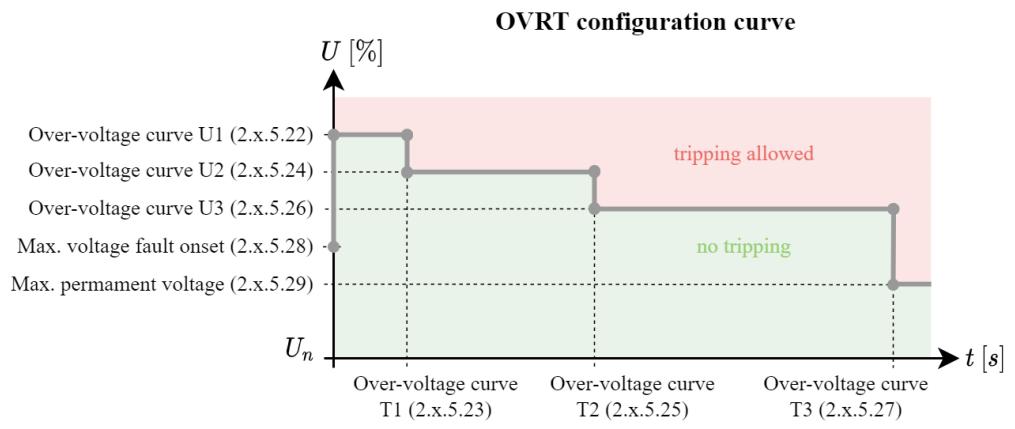

8.2 SPECIAL REACTIVE POWER FUNCTIONALITIES FOR GRID MANAGEMENT
For the EN 50549-1 (Europe), the CEI 0-21 (Italy) and other grid codes, some special requirements are requested regarding the reactive power management. The figures below give the behavior of the next1. See the nextOS manual of the detailed programming of those functions (activation of Q(U), Q(P), ...).
P-Q diagram of the next1 :
P-Q capability of nx1 6500-48

Reduced P-Q diagram
P-Q capability of nx1 6500-48 according to CEI 0-21

General U-Q diagram :
U-Q capability of nx1 6500-48 with P = 80 [%] of Sn

The reactive power production can be controlled with settings according to the DSO requirements.
Q = f(U) and (φ) = f(P) curves

| Setpoint | Q=f(U) curve | cos(phi)=f(P) curve |
| y1 | Reactive power curve Q1 (2.x.5.54) | Reactive power curve cos(phi) OE1 (2.x.5.66) |
| y2 | Reactive power curve Q2 (2.x.5.55) | Reactive power curve cos(phi) OE2 (2.x.5.67) |
| y3 | Reactive power curve Q3 (2.x.5.56) | Reactive power curve cos(phi) UE1 (2.x.5.68) |
| y4 | Reactive power curve Q4 (2.x.5.57) | Reactive power curve cos(phi) UE4 (2.x.5.69) |
| x1 | Reactive power curve U1 (2.x.5.58) | Reactive power curve P1 (2.x.5.70) |
| x2 | Reactive power curve U2 (2.x.5.59) | Reactive power curve P2 (2.x.5.71) |
| x3 | Reactive power curve U3 (2.x.5.60) | Reactive power curve P3 (2.x.5.72) |
| x4 | Reactive power curve U4 (2.x.5.61) | Reactive power curve P4 (2.x.5.73) |
See also the nextOS user manual for explanation about configuration of the next device.
8.3 POWER LIMITATION WITHIN DACHCZ ZONE
With some grid codes, the next1 has a limited power of 3.6 kVA in interaction with the grid. 3.6 kVA is a limit power per phase given for an appliance given in the standard D-A-CH-CZ 2 .
The nominal power of the nx1 in interaction to the grid connexion is set to 3.6 kVA in the D-A-CH-CZ zones to respect that point
In offgrid when the next1 is disconnected from the grid, it has higher capacity, 4.5kW nominal, 6kW surge from experience in OFFGRID, we know that it is very important to have surge power: starting loads, compressors, ...
On a backed-up phase, there can be more than 3.6kVA, each appliance is smaller but there can be many.
ongrid

offgrid

For D-A-CH-CZ region
8.4 BEHAVIOUR IN CASE OF TROUBLES
Various cases that are handled safely by the next1:
-
In case of overload: the next 1 can give surge power for 5 seconds, for example to start loads, cope with transitions. Then the current will be limited, and the voltage drops. After 5 seconds if the load didn't decrease the unit stops.
• In case of short-circuit: -
In offgrid: the short-circuit is detected and the unit stops after one second
On grid: the short circuit current can be very big, the next will wait for the protections (breakers) to open.
• In case of battery undervoltage: the next1 stops
• In case of battery overvoltage: the next1 stops
- In case the internal temperature measurements unit becomes high, the next1 has a programmed strategy to try to prolong its operation and keep the power supply service going as long as possible:
o ventilation is activated at maxim
- in island mode: output voltage is reduced to prolong energy supply by reducing power on a given load.
- when connected to the mains: battery charge/discharge current is reduced, injection current is reduced until a stable temperature point is reached.
- Output power is limited after overheating and until internal temperatures have returned to acceptable levels. If the user sets a higher load, the device will indicate an overload.
8.5 POWER RATING AND DERATING
8.5.1 nx1 6500-48
The next1 is rated 6500W for 30minutes and 4500W nominal power (continuously).
The reference behaviour at 25 degrees is:
Power capability versus time [kW]

In function of the ambient temperature, the next1 has a derating of its nominal power:
Temperature derating

The altitude has also an effect due to the lower air density. Take it into account when dimensioning the system. The reference curve is for 500m above sea level.
9 MAINTENANCE OF THE INSTALLATION
The next1 does not require any particular maintenance.
Regularly:
- Check that the venting is not obstructed by objects or dirt.
- Check the connections (tightening, general condition).
For the rest of the energy system, we can advise:
• See the battery manufacturer for specific advice on battery maintenance.
- Clean regularly your PV panel to optimize the production, check the general state.
The monitoring/datalogging of the next1 will help you to understand the system state.
10 TECHNICAL DATA
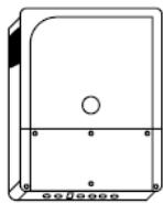

| nx1 6500-48 | nx1 4500-48 | |
| Inverter + battery charger | ||
| Continuous power 25°C | 4500 VA | 3400 VA |
| Power 30 min. 25°C | 6500 VA | 4500 VA |
| Power 5 sec. 25°C | 12000 VA | 10500VA |
| Nominal output voltage, line to neutral | pure sine wave 220/230/240 Vac (±1%) | |
| Nominal output frequency | 50/60 Hz (±0.02%) | |
| Battery charger | ||
| Nominal battery voltage (input range) | 48Vdc | 48 Vdc |
| Battery input range | 38-68 Vdc | 38-68 Vdc |
| Maximum charging current / power | 125 Adc/ 6250 W | 85Adc/4250W |
| AC source (grid or genset) | ||
| Maximum rated current | 80 Aac | |
| Operating voltage range, line to neutral | 176 - 288 Vac | |
| Nominal voltage, line to neutral | 220 - 230 - 240 Vac | |
| Nominal frequency | 50/60 Hz | |
| Overvoltage category (OVC) | III | |
| Grid code compliance | EU Commission Regulation 2016/631 (NC RfG), EN 50549-1:2019, VDE-ARN 4105:2018, IEC 62116, IEC 61727 | |
| AC flex (source or load) | ||
| Maximum rated current | 50 Aac | |
| Operating voltage range, line to neutral | 176 - 288 Vac | |
| Nominal voltage, line to neutral | 220-230-240 Vac | |
| Nominal frequency | 50/60 Hz | |
| General data | ||
| Product dimensions h/w/l | wall-mounted : 182 / 439 / 580 mmrack 19": 175 (3u) / 420 / 550 mmTransport: 275 /495 /630 mm | |
| Product weight / transport weight | 39 kg / 42 kg | 36 kg / 39 kg |
| Multi-units systems | 3 units in parallel, three phased, split phase | |
| Self-consumption OFF / Standby / ON | 3 / 7 / 20 W | |
| Communications | 2x nx communication bus RJ45/8, 1x CAN BMS, 1x RS485i | |
| I/O contacts | 2x digital inputs, 2x analogical inputs, 2x Aux Output rated 16A each, , 1x nx tempSensor | |
| Interfaces | 2x USB (datalogger USB 1-min resolution), 1x LAN (Ethernet, Modbus TCP, studer portal + monitoring APP), nx wifidongle, nx-interface with screen in option | |
| Safety+EMC conformity (CE marketing) | Low Voltage Directive (LVD) 2014/35/EU, EU Electromagnetic Compliance (EMC) 2014/30/EU | |
| Ingress protection IEC60529 | IP65 | |
11 CONFORMITY
The inverter charger next1 described in this manual has been designed and manufactured in accordance with the following European directives:
• Low Voltage Directive (LVD) 2014/35/EU
• Electromagnetic Compliance (EMC) Directive 2014/30/EU
- Restriction of use of certain hazardous substances (RoHS) (Directive) 2011/65/EU
Official up to date EU declaration of conformity (DoC) can be found on our website www.studer-innotec.com as well as some certifications performed by external accredited certification bodies.
11.1 GRID CERTIFICATIONS
The next1 has grid codes for :
• EN50549-1 (pending)
• VDE-AR-N 4105:2018-11 (tested according to DIN VDE V 0124-10:2020-06) (pending)
• CEI 0-21 with UFLEX batteries (Italy)
• ... more to come
And regional setting associated. Select the proper country during the wizard
The grid code is selected during the commissioning with the wizard. To be compliant the installer must not change any individual settings concerning grid code later. The modification of grid code or individual settings concerning that subject is protected by a user code EXPERT given only to professionals.
Scan of grid code certification test result are available on the product page of the certification can be found on the product webpage.
12 PRODUCT RECYCLING
The next1 meets the European directive 2011/65/EU on hazardous substances and does not contain the following elements: lead, cadmium, mercury, hexavalent chrome, PBB or PBDE.
To dispose of this product, please use the service for the collection of electrical waste and observe all obligations in force in the place of purchase.


next 1

© copyright Studer-Innotec
May change without notice
STUDER Innotec SA
Rue des Casernes 57
1950 Sion – Switzerland
Tel. : +41(0) 27 205 60 80
Fax : +41(0) 27 205 60 88
info@studer-innotec.com
www.studer-innotec.com


- NEXT
- SMART HYBRID INVERTER CHARGER WITH EMBEDDED COMMUNICATION
- ACCESSORIES IN OPTION
- CONTENTS
- INTRODUCTION
- GLOSSARY
- GENERAL INFORMATION
- HANDLING AND MOUNTING
- WIRING
- POWER-UP OF THE EQUIPMENT
- USER INTERFACE: THE EMBEDDED WEB INTERFACE
- OPERATION AND PERFORMANCES
- MAINTENANCE OF THE INSTALLATION
- SYMBOLS AND CONVENTIONS
- MODELS NAMING
- ABOUT THIS USER MANUAL
- IMPORTANT SAFETY INSTRUCTIONS
- QUALITY AND WARRANTY
- EXCLUSION OF WARRANTY
- EXCLUSION OF LIABILITY
- HANDLING AND MOVING
- STORAGE
- DIMENSIONS
- UNPACKING AND MOUNTING
- MOUNTING PLACE
- UNPACKING AND MOUNTING PROCESS
- MOUNTING OF THE NX-INTERFACE (OPTION)
- MOUNTING INSTRUCTIONS
- GENERAL OVERVIEW
- SYSTEM BLOCK DIAGRAM
- GENERAL RECOMMENDATIONS
- CONNECTIONS OVERVIEW
- MAX PERMISSIBLE CABLE CROSS-SECTIONS, TIGHTENING TORQUES
- CONNECTING THE AC (ALTERNATIVE CURRENT)
- INSULATION TESTS
- SIZING OF AC PROTECTIVE DEVICES
- AC NEUTRAL AND EARTHING SYSTEM
- STATIONARY INSTALLATION AND NEUTRAL CONTINUITY
- MOBILE INSTALLATION OR INSTALLATION CONNECTED TO THE GRID VIA PLUG CONNECTOR
- CONNECTING THE BATTERY
- EARTHING OF BATTERY
- BATTERY WITH COMMUNICATING BMS: CAN CONNECTION
- BATTERY TEMPERATURE SENSOR CONNECTION (NX-TEMPSENSOR IN OPTION)
- NOTES ON BATTERIES
- DIMENSIONING THE BATTERY
- PRECAUTIONS WHEN USING BATTERIES
- LIGHTNING PROTECTION
- CONNECTING THE COMMUNICATIONS CABLES
- CONNECTING THE STUDER COMMUNICATIONS CABLES
- CONNECTION OF THE NX-INTERFACE (OPTION)
- CONNECTION TO INTERNET
- WIRED CONNECTION
- WI-FI CONNECTION
- WIRING AUXILIARY I/O
- COMMAND INPUTS: DIGITAL AND ANALOG INPUTS
- AUXILIARY RELAYS
- USB PORTS
- ISOLATED COMMUNICATION: RS485I AND CAN BMS
- COMMUNICATION FOR COMPATIBLE DEVICES
- THE RS-485I CONNECTION IS FOR OFFICIAL COMPATIBLE ACCESSORIES FOR THE NEXT1 ONLY
- THE CAN IS EXCLUSIVELY FOR CONNECTION TO THE BATTERY BMS
- MULTI-UNIT CONFIGURATIONS
- PARRALLELLING AC IN MULTI-UNIT
- THREEPHASED CONNECTION
- SPLITPHASE CONNECTION
- BATTERIES IN MULTI-UNITS
- EXTENSION OF AN EXISTING INSTALLATION
- SPECIAL CONFIGURATIONS
- AC-SOLAR: CONNECTION OF SOLAR INVERTER IN AC-COUPLING
- OPERATION WITH A POWER METER
- DC-SOLAR: INTEGRATION OF STUDER SOLAR CHARGERS VARIO IN THE SYSTEM
- XCOM485I-NX CONFIGURATION
- MINIGRIDS WITH AC-COUPLING
- INITIAL CONFIGURATION REQUIRED
- FRONT PANEL BUTTON
- FRONT PANEL LED INDICATOR
- SPECIAL CASES
- BEEP INDICATOR (BUZZER)
- FIRST COMMISSIONING WITH THE WEB INTERFACE
- MINIMAL COMMISSIONNING INFORMATION
- AC-GRID
- AC-GENSET
- BATTERIES
- INTERNET CONNECTION
- CONFIGURATION WIZARD
- USE OF WIFI CLIENT AT THE END OF THE PROCESS
- DNS TROUBLESHOOTING: "PAGE NOT FOUND
- GATEWAY CONNECTIVITY CHECK
- TROUBLESHOOTING: MANUAL RESET OF FACTORY SETTINGS FOR GATEWAY CONNECTIVITY
- TURN ON A DISABLED GATEWAY
- FACTORY SETTINGS RESET
- GRID CONNECTION OPERATING RANGE
- CONTINUOUS OPERATING RANGE
- GRID FAULT RIDE-THROUGH CAPABILITY
- SPECIAL REACTIVE POWER FUNCTIONALITIES FOR GRID MANAGEMENT
- POWER LIMITATION WITHIN DACHCZ ZONE
- BEHAVIOUR IN CASE OF TROUBLES
- POWER RATING AND DERATING
- NX
- TECHNICAL DATA
- CONFORMITY
- GRID CERTIFICATIONS
- PRODUCT RECYCLING
Brand : STUDER
Model : nx 16500 -48
Category : Hybrid inverter