
N4200W - Television VIEWSONIC - Free user manual and instructions
Find the device manual for free N4200W VIEWSONIC in PDF.
| Product type | LCD TV |
| Brand | ViewSonic |
| Model | N4200W |
| Screen size (diagonal) | 42 inches (107 cm) |
| Resolution | Full HD 1920 x 1080 pixels |
| Dimensions with stand (W x H x D) | 1020 x 680 x 230 mm |
| Dimensions without stand (W x H x D) | 1020 x 620 x 95 mm |
| Weight with stand | 15.2 kg |
| Weight without stand | 13.8 kg |
| Power supply | 100-240 V AC, 50/60 Hz |
| Power consumption (typical) | 110 W |
| Standby power consumption | Less than 1 W |
| Input connectors | HDMI (x2), VGA, component input, composite input, USB |
| Tuner | DTT (DVB-T) |
| Built-in speakers | 2 x 10 W |
| Main features | Remote control, OSD menu, image and sound settings, child lock, timer |
| Maintenance and cleaning | Use a soft, dry cloth for the screen and casing. Do not use abrasive or liquid products. |
| Safety | Wall mount compatible with VESA 400 x 400 mm |
| Spare parts and repairability | Remote control, power cable, stand available. Repairs possible by an authorized technician. |
| General information | User manual of 42 pages including installation, use, maintenance and troubleshooting instructions. |
Frequently Asked Questions - N4200W VIEWSONIC
User questions about N4200W VIEWSONIC
0 question about this device. Answer the ones you know or ask your own.
Ask a new question about this device
Download the instructions for your Television in PDF format for free! Find your manual N4200W - VIEWSONIC and take your electronic device back in hand. On this page are published all the documents necessary for the use of your device. N4200W by VIEWSONIC.
USER MANUAL N4200W VIEWSONIC
Compliance Information....1
Declaration of RoHS Compliance 2
Important Safety Instructions....3
Copyright Information 4
Product Registration 4
Cleaning the LCD Display....5
Disclaimer....5
Getting Started
Package Contents ....6
The wall type is installed....7
Move loudspeaker secure....8
View of the Product 9
Remote Control 12
Installation 14
RS232 Module....21
Basic Operation....24
OSD Functions
OSD style and operation tips....26
OSD Operation....26
Other Information
Specifications 35
Troubleshooting....36
Customer Support 38
Limited Warranty 39
Compliance Information
FCC Statement
This device complies with part 15 of FCC Rules. Operation is subject to the following two conditions: (1) this device may not cause harmful interference, and (2) this device must accept any interference received, including interference that may cause undesired operation.
This equipment has been tested and found to comply with the limits for a Class B digital device, pursuant to part 15 of the FCC Rules. These limits are designed to provide reasonable protection against harmful interference in a residential installation. This equipment generates, uses, and can radiate radio frequency energy, and if not installed and used in accordance with the instructions, may cause harmful interference to radio communications. However, there is no guarantee that interference will not occur in a particular installation. If this equipment does cause harmful interference to radio or television reception, which can be determined by turning the equipment off and on, the user is encouraged to try to correct the interference by one or more of the following measures:
- Reorient or relocate the receiving antenna.
- Increase the separation between the equipment and receiver.
- Connect the equipment into an outlet on a circuit different from that to which the receiver is connected.
- Consult the dealer or an experienced radio/TV technician for help.
Warning: You are cautioned that changes or modifications not expressly approved by the party responsible for compliance could void your authority to operate the equipment.
Following information is only for EU-member states:
The mark shown to the right is in compliance with the Waste Electrical and Electronic Equipment Directive 2002/96/EC (WEEE).
The mark indicates the requirement NOT to dispose the equipment as unsorted municipal waste, but use the return and collection systems according to local law.
Declaration of RoHS Compliance
This product has been designed and manufactured in compliance with Directive 2002/95/EC of the European Parliament and the Council on restriction of the use of certain hazardous substances in electrical and electronic equipment (RoHS Directive) and is deemed to comply with the maximum concentration values issued by the European Technical Adaptation Committee (TAC) as shown below:
| Substance | Proposed Maximum Concentration | Actual Concentration |
| Lead (Pb) | 0.1% | < 0.1% |
| Mercury (Hg) | 0.1% | < 0.1% |
| Cadmium (Cd) | 0.01% | < 0.01% |
| Hexavalent Chromium ( Cr^6+ ) | 0.1% | < 0.1% |
| Polybrominated biphenyls (PBB) | 0.1% | < 0.1% |
| Polybrominated diphenyl ethers (PBDE) | 0.1% | < 0.1% |
Certain components of products as stated above are exempted under the Annex of the RoHS Directives as noted below:
Examples of exempted components are:
- Mercury in compact fluorescent lamps not exceeding 5 mg per lamp and in other lamps not specifically mentioned in the Annex of RoHS Directive.
- Lead in glass of cathode ray tubes, electronic components, fluorescent tubes, and electronic ceramic parts (e.g. piezoelectronic devices).
- Lead in high temperature type solders (i.e. lead-based alloys containing 85% by weight or more lead).
- Lead as an allotting element in steel containing up to 0.35% lead by weight, aluminium containing up to 0.4% lead by weight and as a cooper alloy containing up to 4% lead by weight.
Important Safety Instructions
- Read these instructions completely before using the equipment.
- Keep these instructions in a safe place.
- Heed all warnings.
- Follow all instructions.
- Do not use this equipment near water.
- Clean with a soft, dry cloth. If further cleaning is required, see “Cleaning the Display” in this guide for further instructions.
- Do not block any ventilation openings. Install the equipment in accordance with the manufacturer's instructions.
- Do not install near any heat sources such as radiators, heat registers, stoves, or other devices (including amplifiers) that produce heat.
- Do not attempt to circumvent the safety provisions of the polarized or grounding-type plug. A polarized plug has two blades with one wider than the other. A grounding type plug has two blades and a third grounding prong. The wide blade and the third prong are provided for your safety. If the plug does not fit into your outlet, consult an electrician for replacement of the outlet.
-
Protect the power cord from being tread upon or pinched, particularly at the plug, and the point where if emerges from the equipment. Be sure that the power outlet is located near the equipment so that it is easily accessible.
-
Only use attachments/accessories specified by the manufacturer.
-
Use only with the cart, stand, tripod, bracket, or table specified by the manufacturer, or sold with the equipment. When a cart is used, use caution when moving the cart/ equipment combination to avoid injury from tipping over.

-
Unplug this equipment when it will be unused for long periods of time.
-
Refer all servicing to qualified service personnel. Service is required when the unit has been damaged in any way, such as: if the power-supply cord or plug is damaged, if liquid is spilled onto or objects fall into the unit, if the unit is exposed to rain or moisture, or if the unit does not operate normally or has been dropped.
Copyright Information
Copyright © ViewSonic ^® Corporation, 2006. All rights reserved.
ViewSonic, the three birds logo, OnView, ViewMatch, and ViewMeter are registered trademarks of ViewSonic Corporation.
Disclaimer: ViewSonic Corporation shall not be liable for technical or editorial errors or omissions contained herein; nor for incidental or consequential damages resulting from furnishing this material, or the performance or use of this product.
In the interest of continuing product improvement, ViewSonic Corporation reserves the right to change product specifications without notice. Information in this document may change without notice.
No part of this document may be copied, reproduced, or transmitted by any means, for any purpose without prior written permission from ViewSonic Corporation.
Product Registration
To meet your future needs, and to receive any additional product information as it becomes available, please register your product on the Internet at: www.viewsonic.com.
For Your Records
Product Name:
N4200w-2
ViewSonic LCD Display
Model Number:
VS10945-1M
Document Number:
N4200w-2M_UG_ENG Rev. 1A 12-13-06
Serial Number:
Purchase Date:
Product disposal at end of product life
ViewSonic is concerned about the preservation of our environment. Please dispose of this product properly at the end of its useful life. Your local waste disposal company may provide information about proper disposal.
The lamp in this product contains mercury. Please dispose of properly in accordance with environmental laws of your location.
Cleaning the LCD Display
• Make sure the LCD Display is turned off.
• Never spray or pour any liquid directly onto the screen or case.
To clean the screen:
1 Wipe the screen with a clean, soft, lint-free cloth. This removes dust and other particles.
2 If still not clean, apply a small amount of non-ammonia, non-alcohol based glass cleaner onto a clean, soft, lint-free cloth, and wipe the screen.
To clean the case:
1 Use a soft, dry cloth.
2 If still not clean, apply a small amount of non-ammonia, non-alcohol based, mild non-abrasive detergent onto a clean, soft, lint-free cloth, then wipe the surface.
Disclaimer
ViewSonic ^® does not recommend the use of any ammonia or alcohol-based cleaners on the LCD display screen or case. Some chemical cleaners have been reported to damage the screen and/or case of the LCD display. ViewSonic will not be liable for damage resulting from use of any ammonia or alcohol-based cleaners.
Getting Started
Congratulations on your purchase of a ViewSonic ^® LCD display.
Important! Save the original box and all packing material for future shipping needs.
Package Contents
Your LCD display package includes:
- LCD Display
- VGA Cable
-
Quick Start Guide
-
Power Cable
• Universal Remote Control with batteries
• ViewSonic User Guide
natural_image
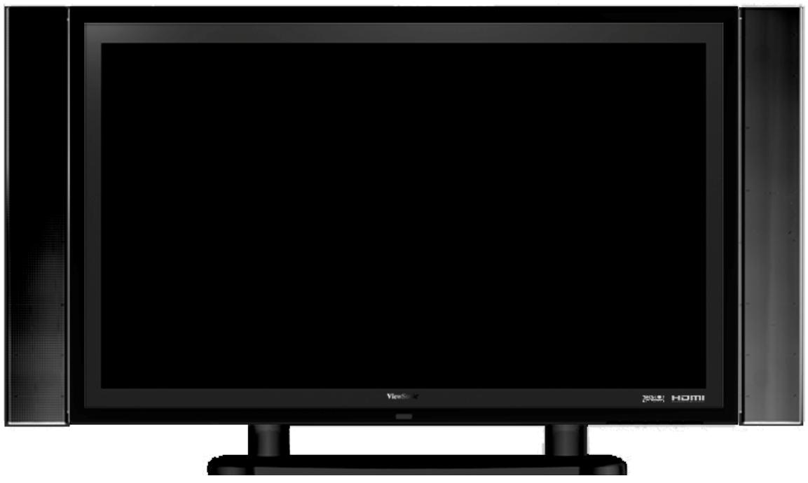
Front view of a black CRT television monitor with 'Viste' branding and 'HOME' text, mounted on a stand (no additional signage or symbols visible)The wall type is installed
natural_image
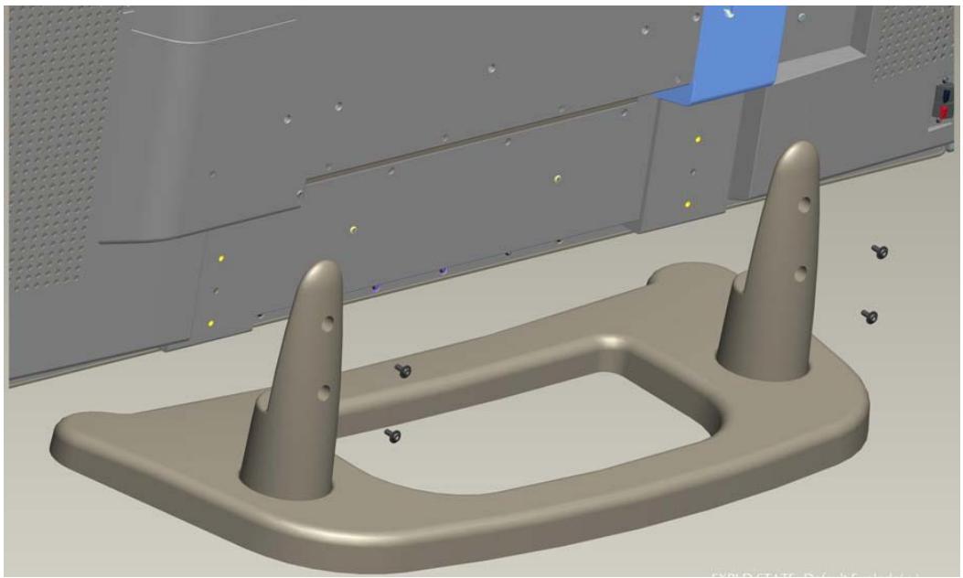
3D CAD model of a mechanical component with two protruding pins and a U-shaped base, shown in perspective view (no text or symbols)Use only approved wall-mounting brackets advised by ViewSonic or your local distributor. To install the wall-mounting brackets to LCD display and fix LCD display to the wall safely, please use the following guidelines:
- Cut off the power.
- Set the LCD display on a table or work surface, screen-down with a towel or woolen blanket between the screen and the surface to protect the display.
- Disassemble 6 screws in the base.
- According to the wall type instruction, fix LCD display to the wall.
Move loudspeaker secure
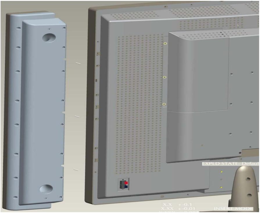
natural_image
3D CAD model of a computer monitor with external casing and internal grid structure (no text or symbols on the model itself)To detach the loudspeakers from the LCD display, please read the following guidelines:
- Cut off the power.
- Disassemble 6 screws of the back loudspeaker(3 screws on each side).
- Exert oneself outward, remove the loudspeaker
View of the Product
Front
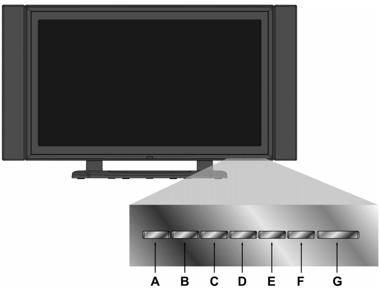
| A | INPUT | Select input sources |
| B | MENU | Turn OSD menu ON/OFF |
| C | VOL- | Decrease volume or adjust a highlighted control decreasingly while in OSD menu |
| D | VOL + | Increase volume or adjust a highlighted control increasingly while in OSD menu |
| E | CH √ | Channel down/ Scroll down |
| F | CH ∧ | Channel up/ Scroll up |
| G | POWER | Turn the power ON/OFF |
Back
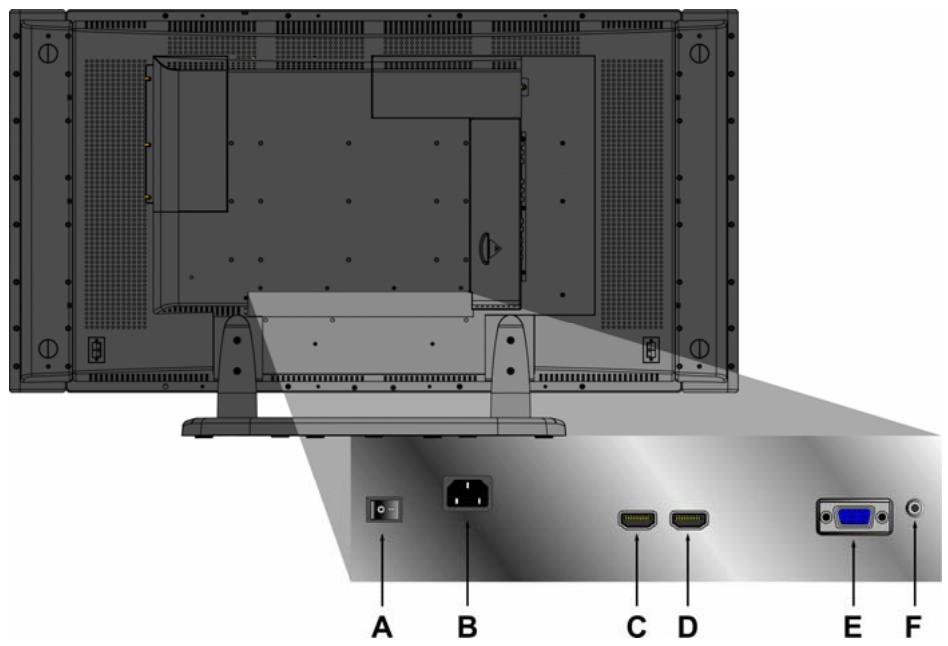
| A | POWER S/W | Power S/W |
| B | AC IN | Using cable provided, connect a power source. |
| C | HDMI(1) | Have one HDMI cable terminals of your DVD player. |
| D | HDMI(2) | Have one HDMI cable terminals of your DVD player. |
| E | VGA | Connect the VGA cable output of PC to the VGA terminal input. |
| F | PC STEREO | Connect the Audio in cable from audio output of your PC to the audio input terminal. |
Component
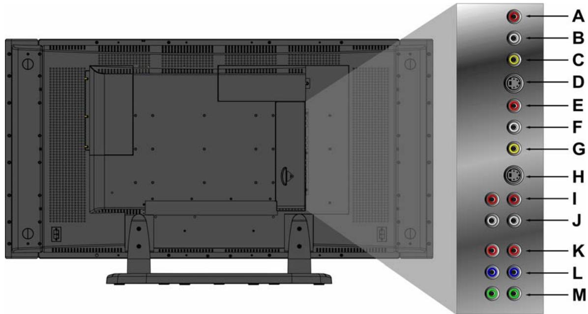
| A | R | Connect Video/Audio cable from compatible devices into the side jack. |
| B | L | Connect Video/Audio cable from compatible devices into the side jack. |
| C | VIDEO | Connect the external video device such as VCR, DVD, and video game into this jack. |
| D | S-V1 | Connect the external video device such as VCR, DVD, and video game into this jack. |
| E | R | Connect Video/Audio cable from compatible devices into the side jack. |
| F | L | Connect Video/Audio cable from compatible devices into the side jack. |
| G | VIDEO | Connect the external video device such as VCR, DVD, and video game into this jack. |
| H | S-V2 | Connect the external video device such as VCR, DVD, and video game into this jack. |
| I | R | Connect Audio cable from compatible devices into the side jack. |
| J | L | Connect Audio cable from compatible devices into the side jack. |
| K | Pr/Cr | Connect the external video device into this jack. |
| L | Pb/Cb | Connect the external video device into this jack. |
| M | Y | Connect the external video device into this jack. |
Remote Control
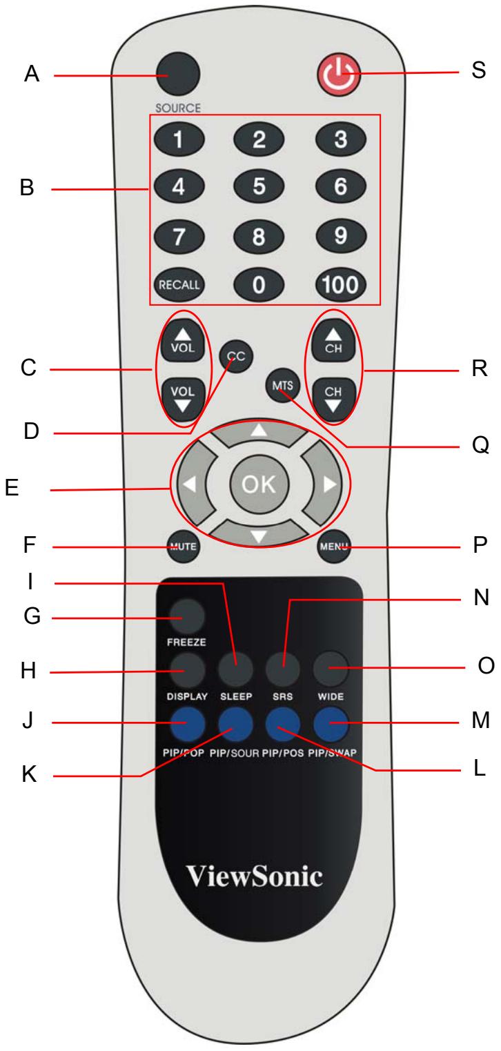
Remote control button function as follow
| A | Source button | Select Input Source |
| B | 0~100+ number button | No functions |
| C | Volume | Adjust Volume |
| D | CC button | Close Caption |
| E | UP/DOWN/LEFT/RIGHT/ ENTER button | UP/DOWN for OSD function select and LEFT/ RIGHT for function adjustVOL- and VOL+ button=adjust the volume when there is no OSD menu display. CH~ and CH~ = change the OSD menu display (For certain models) |
| F | MUTE button | Mute On/Off |
| G | FREEZE | When the program information you want to capture, press button. Press again, and the picture is released |
| H | DISPLAY | Display the sources and time |
| I | SLEEP | Set timer to turn off the Display |
| J | PIP/POP (Guide) | Activate PIP feature (Activate Guide) |
| K | PIP/SOUR | Press to toggle the Sub picture between PIP |
| L | PIP/POS | Change the display position of the Sub Picture in PIP mode |
| M | PIP/SWAP | Toggles between input sources for the Main and Sub picture |
| N | SRS | Enable/Disable Surround Sound |
| O | WIDE | Change Aspect Ratio |
| P | Menu | Display menu or exit OSD menu |
| Q | MTS | No function |
| R | Channel | No function |
| S | POWER | Power ON/OFF |
Installation
1. Insert Remote Control Batteries
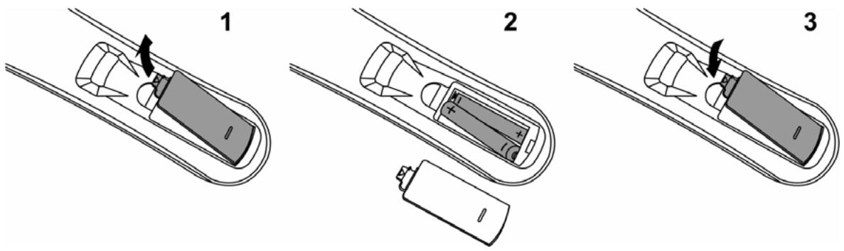
1 Remove the battery cover by pulling then lifting the knob on the cover.
2 Insert the batteries, corresponding to the (+) and (-) markings on the battery compartment.
3 Reattach the battery cover.

CAUTION
• Only use the specified AAA batteries.
- Do not mix new and old batteries. This may result in cracking or leakage, which may pose a risk of fire or lead to personal injury.
- Insert batteries according to (+) and (-) markings. Inserting the batteries incorrectly may result in cracking or leakage, which may pose a risk of fire or lead to personal injury.
- Dispose of the battery in accordance with local laws and regulations.
- Keep the battery away from children and pets.
- When the remote control will not be used for an extended period, remove the batteries.
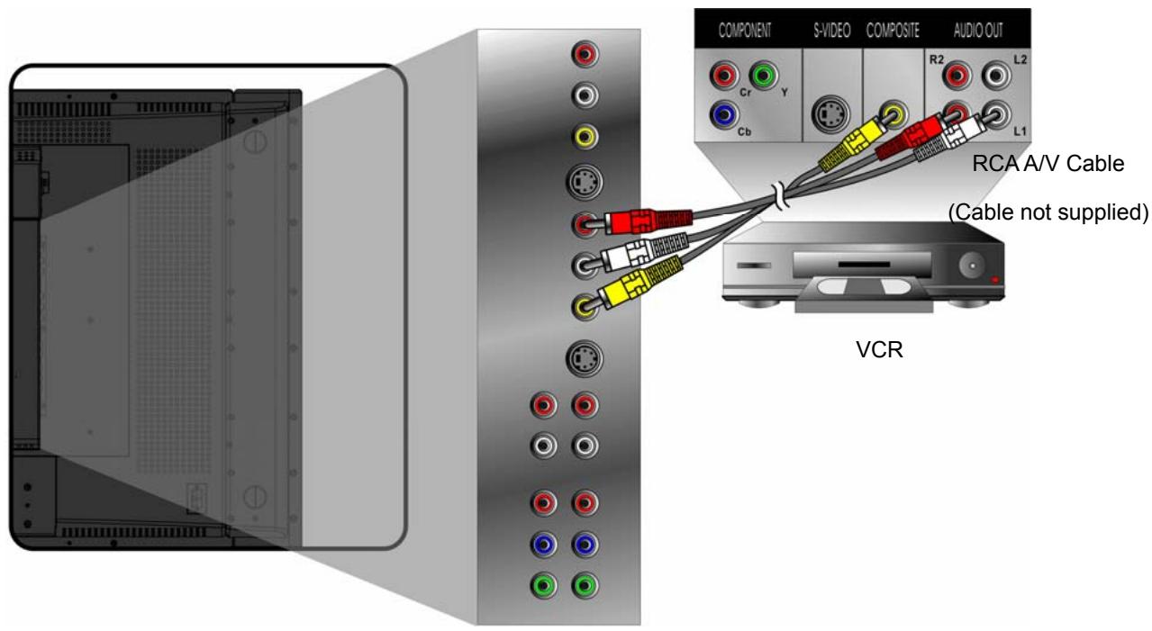
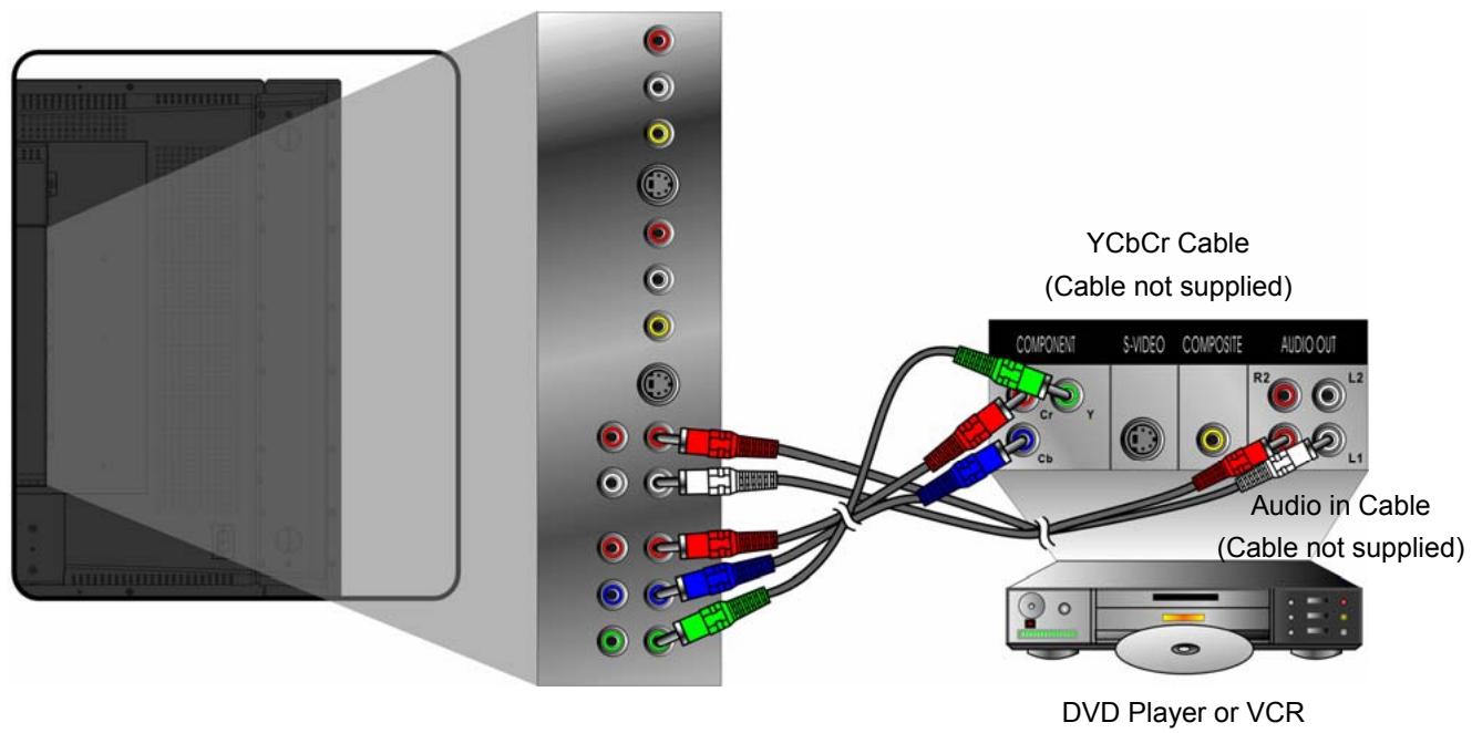
2. Connect AV, S-Video, YCbCr, YPbPr, HDMI to Video Devices
Connect Video/Audio cables from compatible devices into the back panel of N4200W.
AV model:
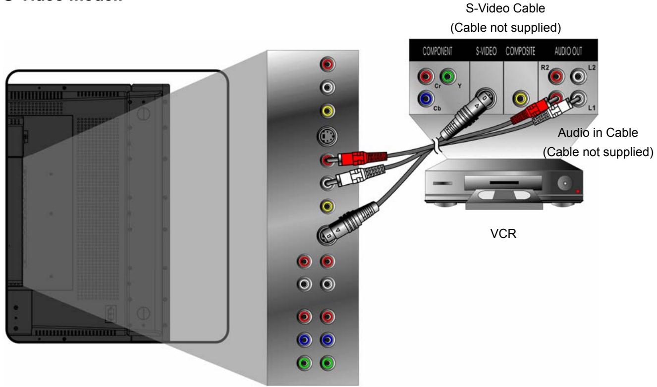
S-Video model:
YCbCr model:
YPbPr model:

HDMI model:
Connect the HDMI cable from DVI output of your DVD player to the HDMI terminal input of N4200W.
HDMI cable
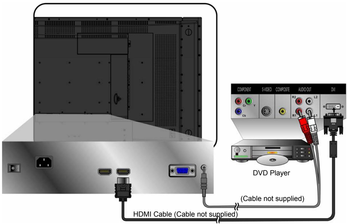
Note: To receive the sound from DVD, please turn on Sound Menu of OSD for selecting HDMI audio to HDMI. However, the input source should be in HDMI.
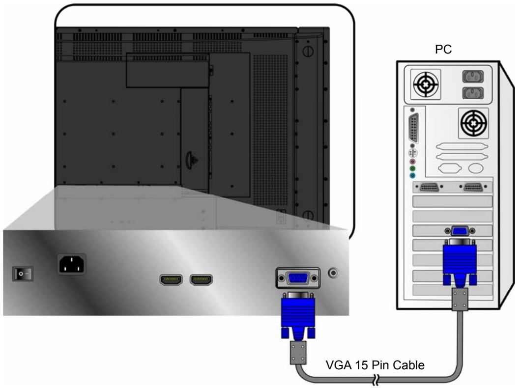
3. Connect to the PC
VGA (15pin D-Sub):
Connect the VGA cable from VGA output of PC to the VGA terminal input of N4200W. PC up to 1280 x 1024, or 1360 x 768 is the preferred resolution.
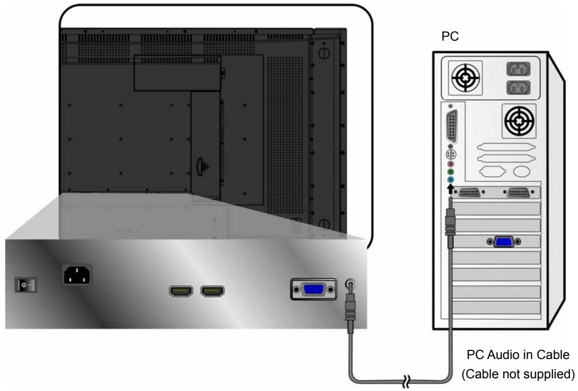
PC Audio in:
Connect the Audio In cable (green) from audio output of your PC to the audio input terminal (green) of N4200W.
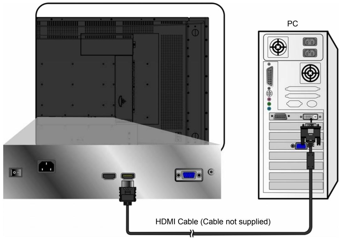
HDMI:
Connect the HDMI cable from DVI output of PC to the HDMI terminal input of N4200W.
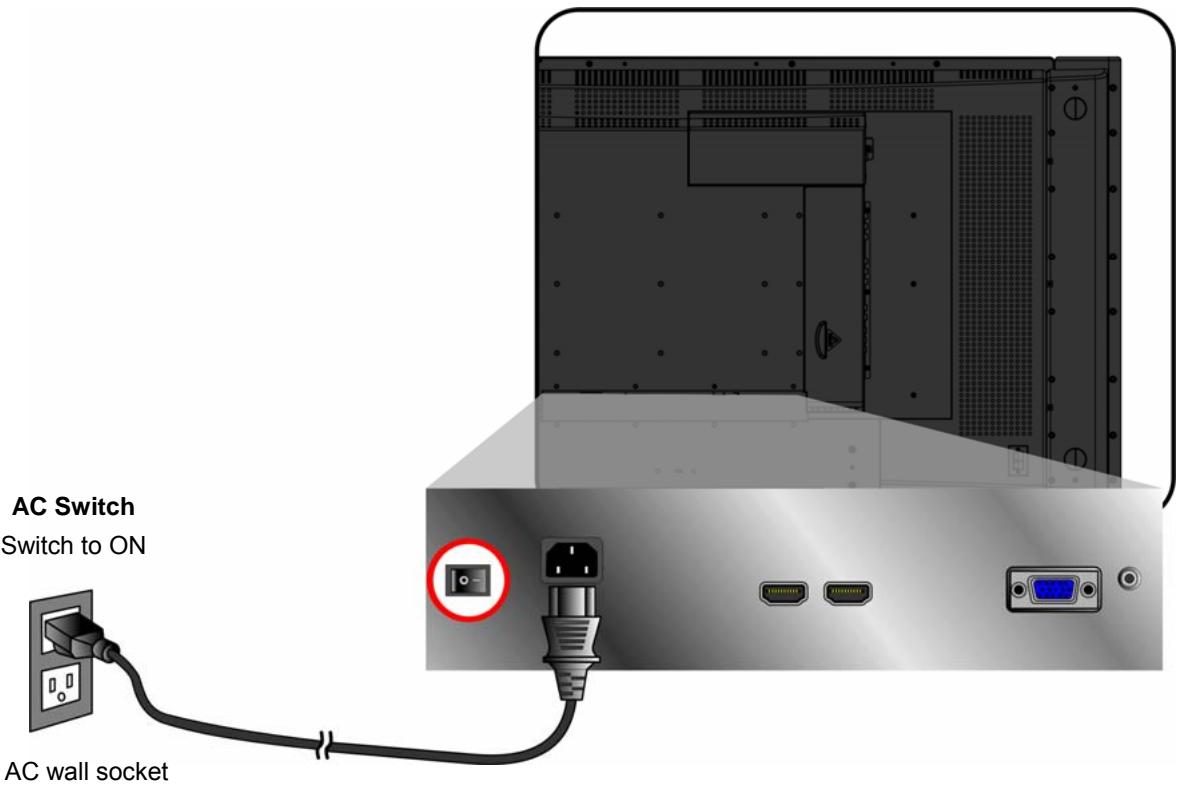
4. Connect power cable
Connect the power cord to the N4200W then to a properly grounded AC outlet. Turn on the AC Switch on the back of N4200W
5. Turn Power ON
Press the Power button under the LCD Display, or press the Power On (red) button on the Remote Control. Turn Video source power ON.
RS232 Module
Besides the basic operations performed via remote control or those buttons on the LCD Display, RS232 module also allows you to realize easy control of the system for simple functions.
Connection to Display and PC
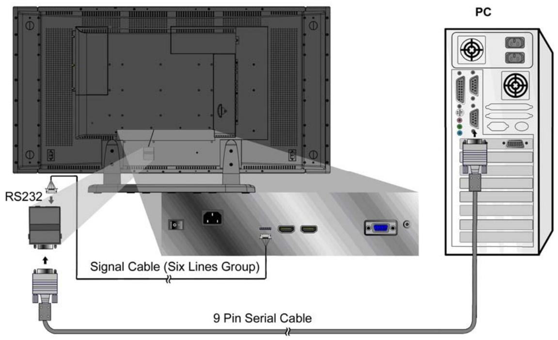
■ RS232 module is installed onto the back of the cabinet and connected with signal cables (six lines group) from the module to the back panel of N4200w as factory setting. The signal line is connected from the Debug port of RS232 to that of the Display.
■ Connect Signal cable from COM port of PC to that of RS232 module.
RS232 Operation
Note: The RS232 user should be familiar with PC and general PC operations.
System Environment
Proper operations of RS232 module for the control of LCD DISPLAY functions are carried out through hyper terminal function in Windows operation system.
New Terminal Creation
Power on your PC and boot in the operational system normally. (Take WinXP as example hereinafter)
Presetting
■ Double click My Computer icon on desktop and open the window.
■ Right click and select Property item in the pop-up menu.
■ Select Hardware label in the System Property window, and click the Device Manager Button (D).
- Click and expand the Port( COM and LPT )folder and select the communication port to be used in the Device Manager window.
■ Double click the corresponding icon and enter into the Port Setting label in the new window.
■ Set the parameters respectively on the label as 9600, 8 bits, No parity, 1 and Stop bit. (Hard Code)
■ Click OK buttons and exit the windows.
Creation
Note: If there is no hyper terminal already created, follow the hereinafter procedures to finish the creation operation.
■ Open Hyper Terminal submenu item in Start Menu on desktop following the procedures as described hereinafter: Start Menu > All Programs > Accessories > Communication > Hyper Terminal, and click it.
■ Input the name (N) of the new hyper terminal connection and select the icon (I) corresponding in Connection Description window, and click OK button to exit.
■ Select the port used practically (N) in the Connection window, including COM1, COM2 or TCP/IP, and click OK button to exit.
■ Adjust the parameter setting in the port property window, complying with the description of HARD CODE. Click OK button and exit.
- Click the Property item (R) in File Menu (F) of the main interface of the hyper terminal created and select the setting label. Set the Terminal Emulation (E) as VT100. Click the ASCII Code Setting button (A) and click the item Display the Characters Input (E) in the ASCII Code Transmission field of the ASCII Code Setting window. Click OK buttons and exit.
Then, the new hyper terminal is created, and you can input commands properly to conduct easy control of the system for certain functions with RS232 module's correct connection with N4200w and the PC.
Operation
To realize certain function of the system, you need to input the corresponding commands properly in the hyper terminal window.
Note: As for the detailed commands for the functions, please refer to the command list attached additionally.
Basic Operation
To operate the function of your LCD Display, you can use your remote control or those buttons on your LCD Display to set input source, change channels, or adjust volume.
Turning on the LCD Display
Before using the LCD Display:
- Insert the power plug.
- Connect external equipment properly.
- Turn on the Main AC Power Switch, located on the rear of the cabinet. (If the LCD Display will not be used for a long period of time, please turn it off)
Power On/Off
To turn the LCD Display on/off :
Press the POWER button under the LCD Display or press the Power button on your remote control to turn on/off the Display. The power LED indicator lights up when the LCD Display is on.
Select input source
To select the required input sources. Use ▲▼ to move the cursor bar, and select by pressing OK.
VOLUME Adjusting
Press VOL-/+ to adjust the volume.
To silence the volume, press MUTE.
If you want to restore volume, press MUTE again.
VOLUME

Source menu
Select the source you want. Select VGA, then PC mode appears. Select others, then AV mode appears.
Main Source Input

OSD Functions
OSD style and operation tips
bar
Picture | Category | Value | |---|---| | Contrast | 50 | | Brightness | 50 | | Color Temp | User | | Red | 50 | | Green | 50 | | Blue | 50 | | Text/Graphic | Graphic | | PIP | PIP | Select: ▼▲ Set: ◀◀ Exit: MenuOSD Operation
Press the “Menu” button on your remote control or right side of the LCD Display to open the OSD Main Menu.
Press ▲ or ▼ button to select the sub menu, and press ◀ or ▶ to enter the sub menu.
Press ▲ or ▼ to select the function you would like to adjust, and then press ◀ or ▶ to adjust it or execute the function.
Press the “Menu” button on your remote control or right side of the LCD Display again to close the OSD Main Menu.
(For PC mode) The 4 icons at the top of the OSD Main menu stand for the 4 sub menus (Picture, Adjust, Audio, Setup).
(For AV mode) The 4 icons at the top of the OSD Main menu stand for the 4 sub menus (Picture, Audio, Setup, Parental)
PC mode
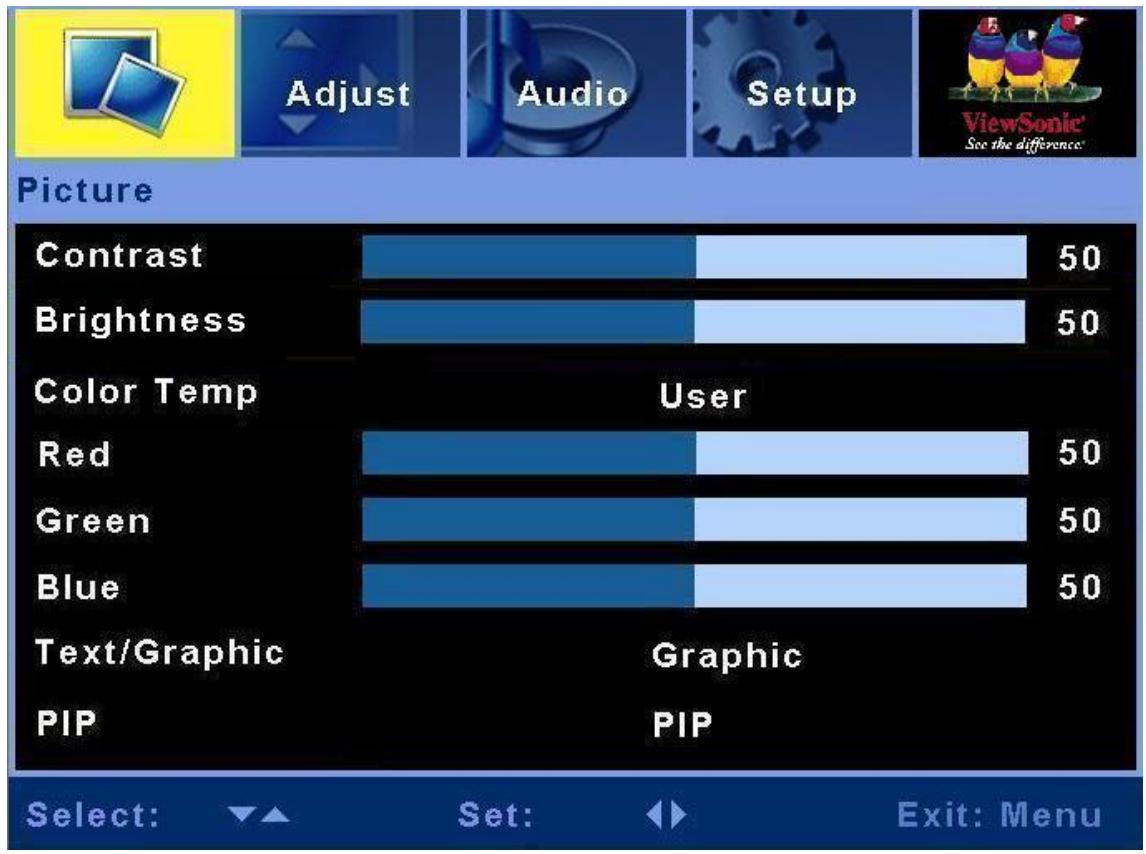
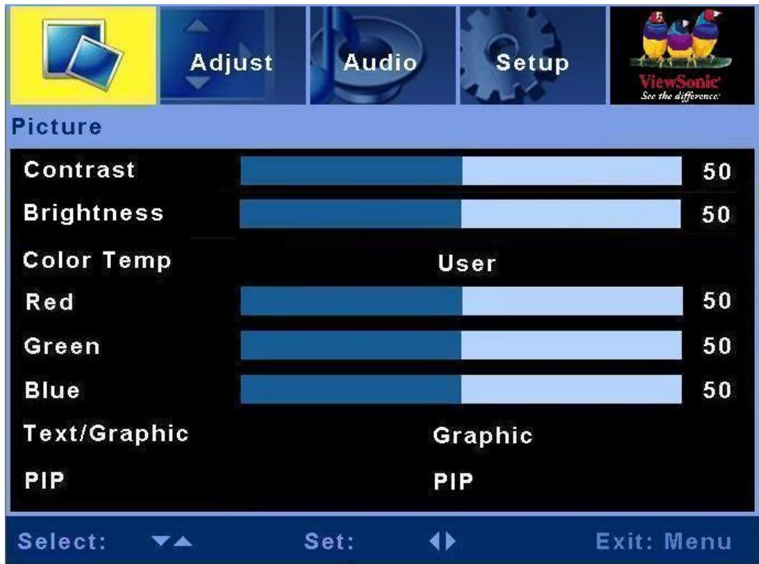
Picture menu
bar
Picture | Category | Value | |---|---| | Contrast | 50 | | Brightness | 50 | | Color Temp | User | | Red | 50 | | Green | 50 | | Blue | 50 | | Text/Graphic | Graphic | | PIP | PIP | Select: Set: Exit: Menu| Item | Description | Operation |
| Contrast | Adjust the contrast level. | ► to increase the contrast.◄ to decrease the contrast. |
| Brightness | Adjust the brightness level. | ► to brighten the display.◄ to darken the display. |
| Color Temp | Some default color temp set is here. Options: STD , Warm, Cold and user | ► or ◀ to select color temp. |
| User | You can adjust Red, Green, Blue to change color temp. | ► to increase the color temp.◄ to decrease the color temp. |
| Text/Graphic | Select Graphic or Text | ► or ◀ to select Graphic or Text. |
| PIP | Select single or Multi-picture functions | ► or ◀ to select Single, PBP, PIP.(HDMI input is not supported in sub picture) |
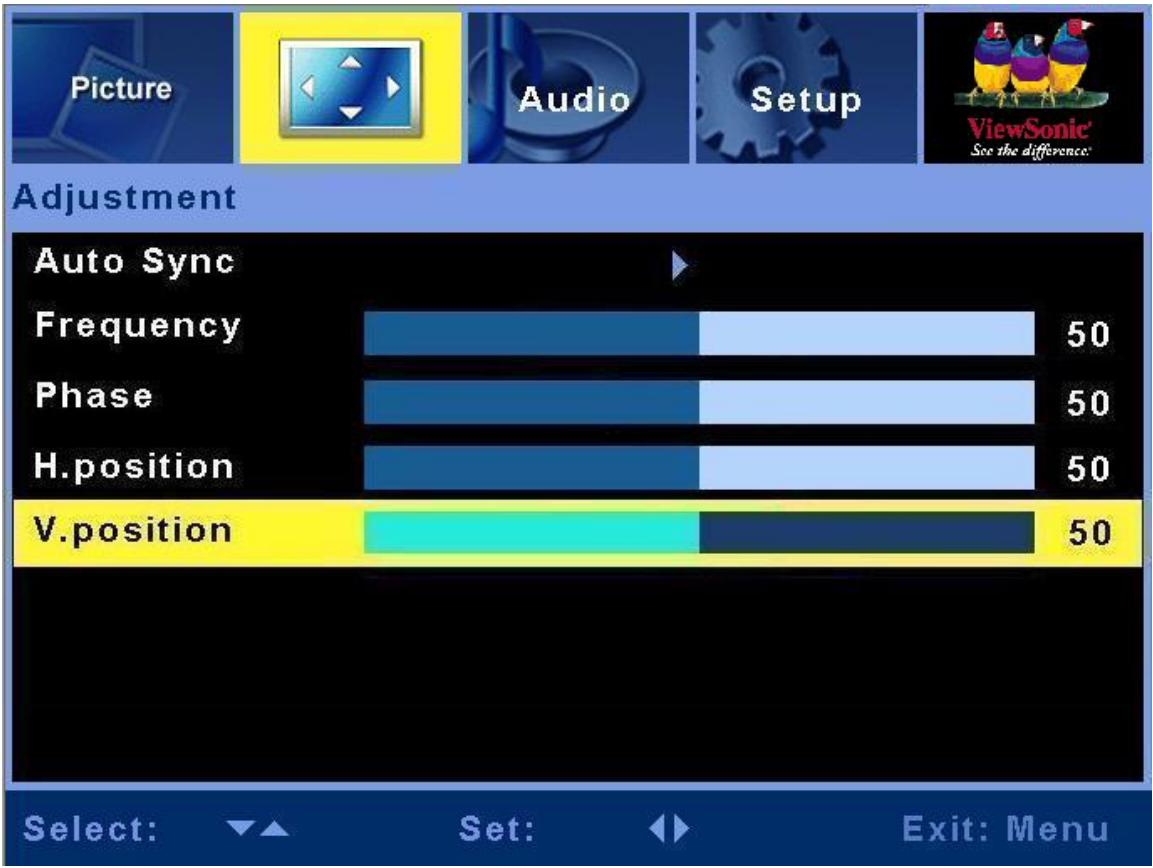
Adjustment menu
bar
| Position | Value | | ------------ | ----- | | Frequency | 50 | | Phase | 50 | | H.position | 50 | | V.position | 50 || Item | Description | Operation |
| Auto Sync | This function auto search the best setting of current input | ► to select Auto Sync. |
| Frequency | Adjust the delay time between horizontal synchronous signal and video | ► to increase the delay time◄ to decrease the delay time. |
| Phase | Adjust the delay time | ► to increase the delay time◄ to decrease the delay time. |
| H.position | Adjust the horizontal position of the main and sub picture in PIP. | ► to move toward the right.◄ to move toward the left. |
| V. position | Adjust the vertical position of the main and sub picture in PIP. | ► to move upward.◄ to move downward. |
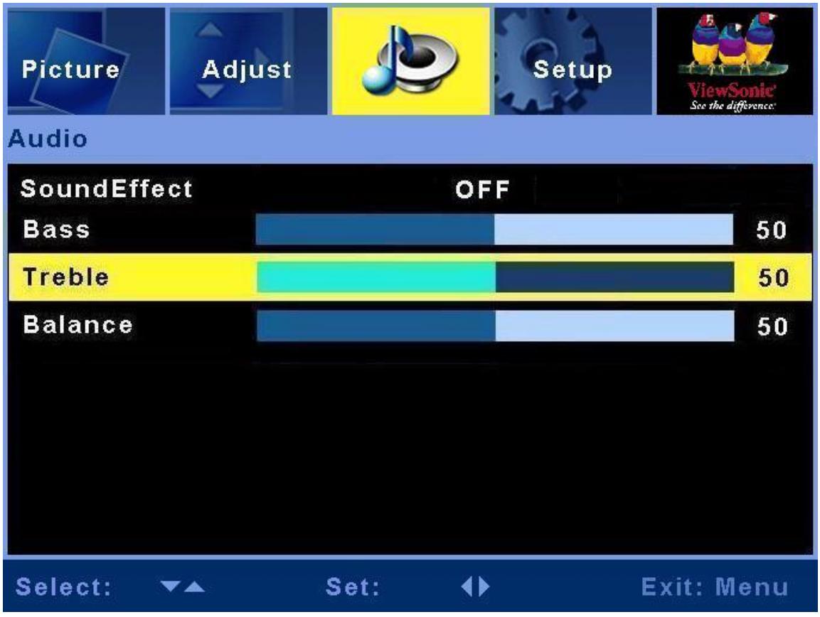
Audio menu
bar
| SoundEffect | OFF | |---|---| | Bass | 50 | | Treble | 50 | | Balance | 50 || Item | Description | Operation |
| SoundEffect | Select Sound Effect | ►or◀ to select SRS Trusurround or OFF. |
| Bass | Adjust the bass. | ► to increase lower-pitched sound.◀ to decrease lower-pitched sound. |
| Treble | Adjust the treble. | ► to increase higher-pitched sound.◀ to decrease higher-pitched sound. |
| Balance | Adjust the left and right audio balance. | ► to emphasize the right speaker.◀ to emphasize the left speaker. |
Setup menu
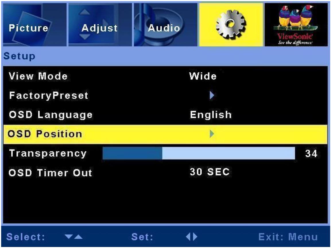
| Item | Description | Operation |
| View Mode | To adjust the picture ratio | ►or◀ to select Normal/Wide |
| FactoryPreset | To recover the original status before shipping out the factory | Press▶ for setup. |
| OSD Language | To select the OSD language | ►or◀ to select OSD language. |
| OSD Position | To select the OSD position on the Display | ►or◀ to select five kinds of OSD position on the Display. |
| Transparency | Adjust OSD's transparency level. | ► to increase the transparency◀ to decrease the transparency. |
| OSD Timer Out | Adjust OSD show time. | ►or◀ to select show time. |
AV mode
Picture menu
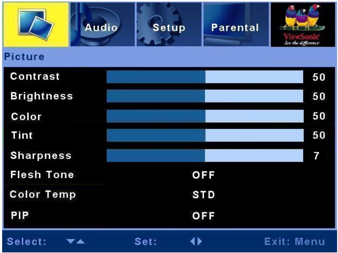
| Item | Description | Operation |
| Contrast | Adjust the contrast level. | ► to increase the contrast.◄ to decrease the contrast. |
| Brightness | Adjust the brightness level. | ► to brighten the display.◄ to darken the display. |
| Color | Adjust the color saturation | ► to increase the color saturation.◄ to decrease the color saturation. |
| Tint | Adjust the Hue | ► to increase the Hue.◄ to decrease the Hue. |
| Sharpness | Adjust the picture sharpness. | ► to sharpen the display.◄ to soften the display. |
| Flesh Tone | Adjust the image color | ► or◄ to select ON or OFF. |
| Color Temp | Some default color temp set is here. Options: STD, Warm and Cold | ► or◄ to select color |
| PIP | Select OFF or Multi-picture functions | ► or◄ to select OFF, PBP, PIP.(HDMI input is not supported in sub picture) |
Audio menu
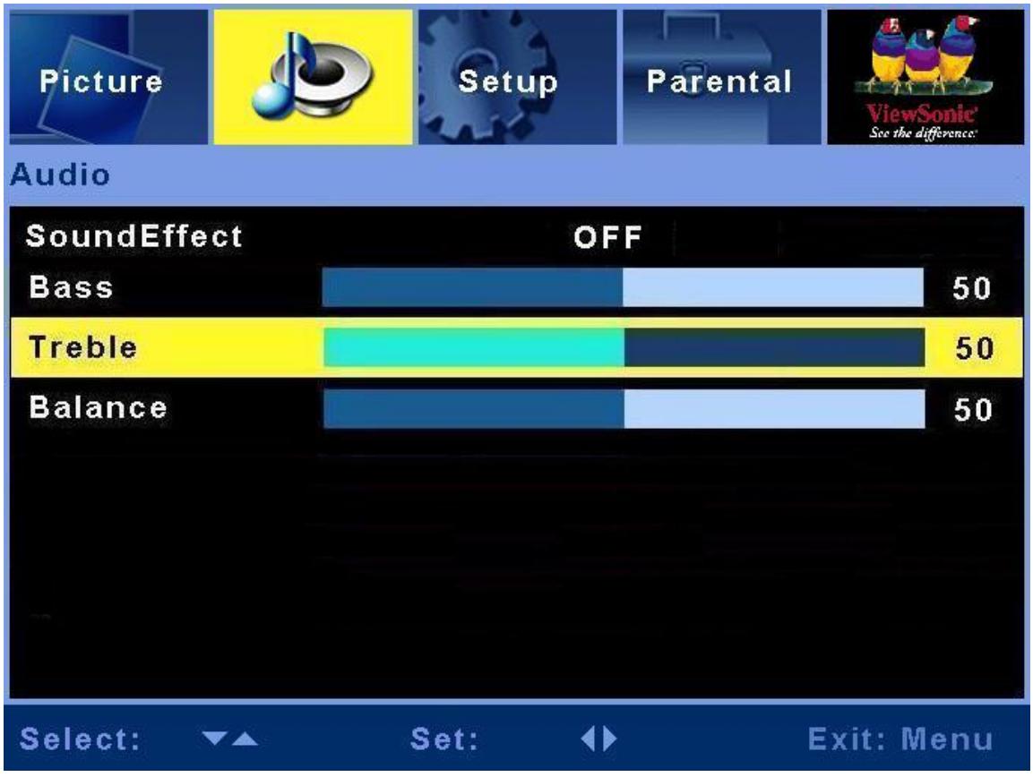
bar
| SoundEffect | OFF | |-------------|-----| | Bass | 50 | | Treble | 50 | | Balance | 50 || Item | Description | Operation |
| SoundEffect | To select sound effect | ►or◀ to select SRS Trusurround or OFF |
| Bass | Adjust the bass. | ► to increase lower-pitched sound.◀ to decrease lower-pitched sound. |
| Treble | Adjust the treble. | ► to increase higher-pitched sound.◀ to decrease higher-pitched sound. |
| Balance | Adjust the left and right audio balance. | ► to emphasize the right speaker.◀ to emphasize the left speaker. |
Setup menu
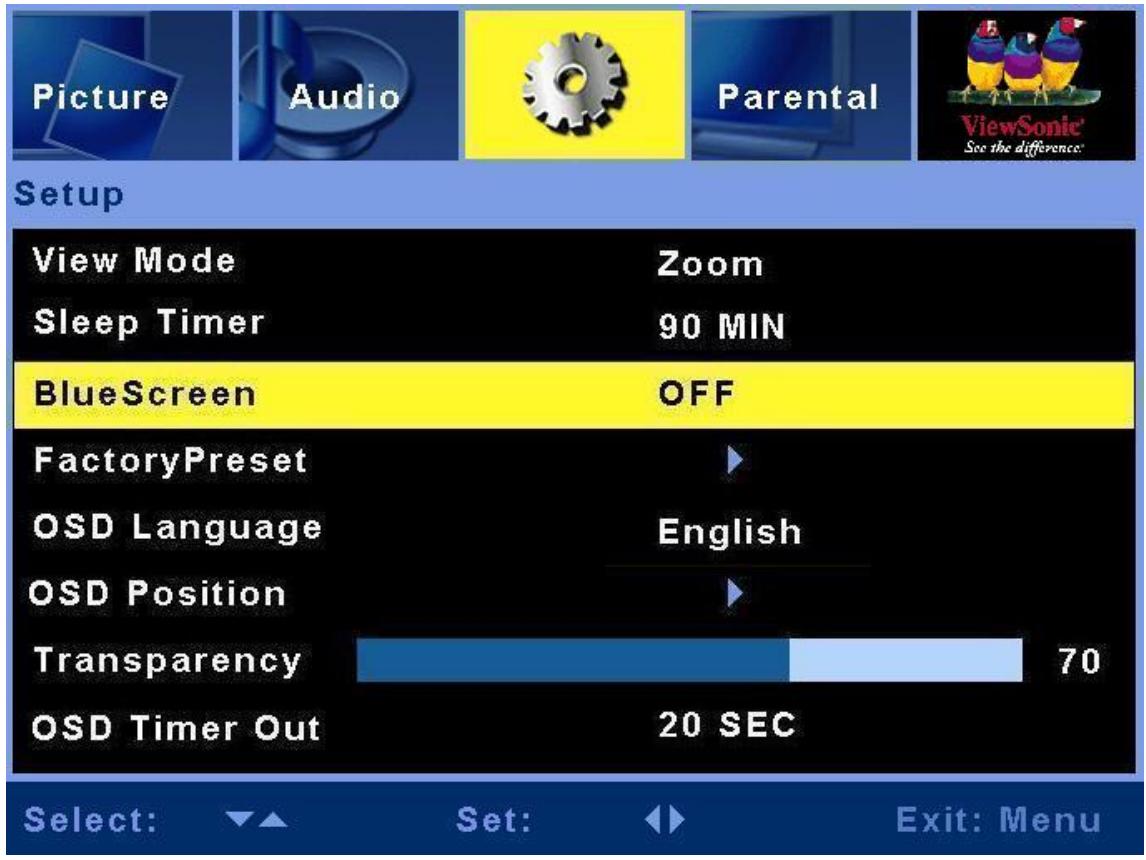
| Item | Description | Operation |
| View Mode | To adjust the picture ratio | ►or◀ to selectSmart/4:3/16:9/Zoom/Wide |
| Sleep Timer | To select sleep timer | ►or◀ to select 30 MIN, 60 MIN, 90MIN, 120 MIN, 150 MIN or OFF. |
| BlueScreen | To select background color when no input. | ►or◀ to select ON or OFF. |
| FactoryPreset | To recover the original status before shipping out the factory | Press▶ for setup. |
| OSD Language | To select the OSD language | ►or◀ to select OSD language. |
| OSD Position | To select the OSD position on the Display | ►or◀ to select five kinds of OSD position on the Display. |
| Transparency | Adjust OSD's transparency level. | ► to increase the transparency◀ to decrease the transparency. |
| OSD Timer Out | Adjust OSD show time. | ►or◀ to select show time. |
Parental Lock
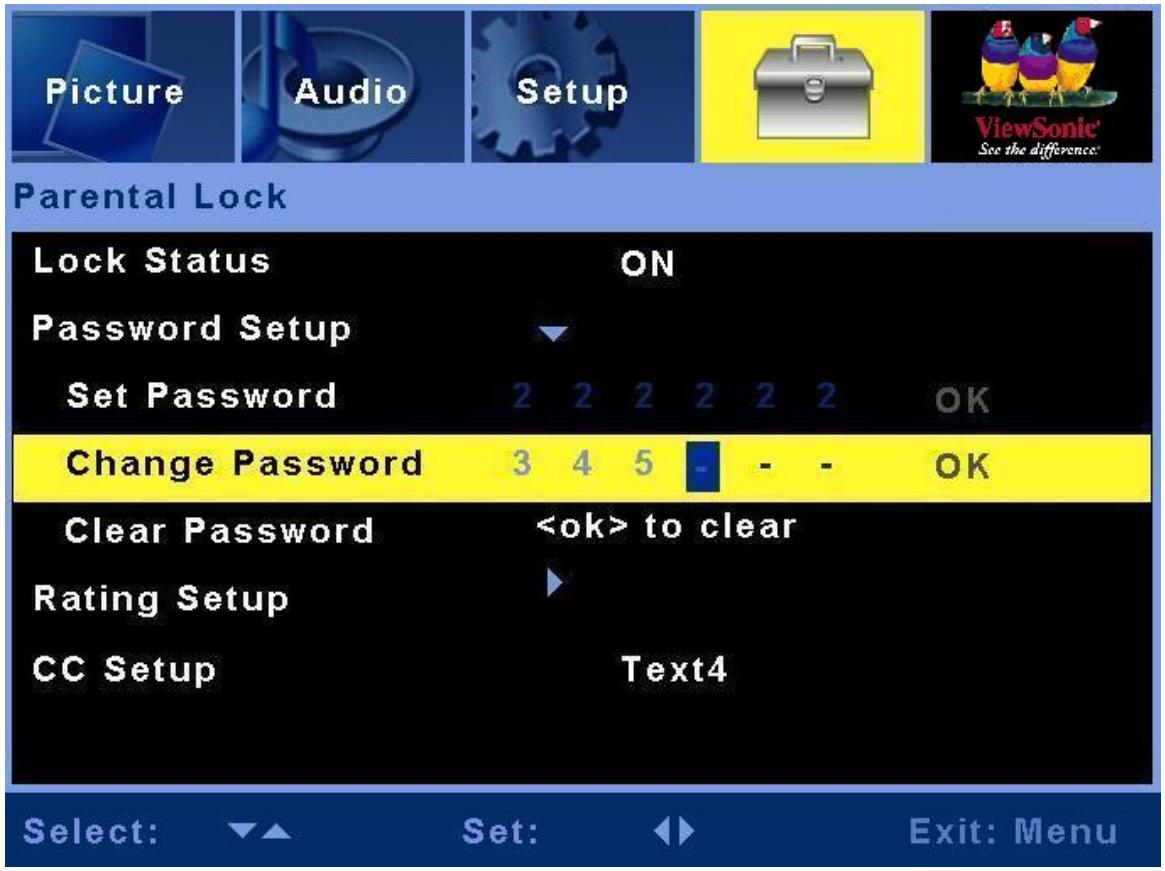
| Item | Description | Operation |
| Lock Status | Adjust the Parental Lock status | ►or◀ to select on or off. |
| Password Setup | Setup the Parental Lock password | press▶, then enter the number as the password you hope. |
| Rating Setup | Setup the film rating classification | press▶, then select the classification you want and press OK. |
| CC Setup | To select Close caption | ►or◀ to select Text1~4, CC1~4, or OFF. |
Other Information
Specifications
| LCD | Type | 42.02" view able | |
| Color Filter | 0.681 mm (H) x 0.227 (V) mm pixel pitch | ||
| Glass surface | RGB vertical stripe | ||
| Anti-Glare | |||
| Input signal | RGB | RGB analog (0.7/1.0 Vp-p, 75 ohms) | |
| Separate Sync, | |||
| fn:30-80 kHz, fv:50-75 Hz | |||
| Video | D-sub x 1 ,HDMI x 2, YPbPr/YCbCr x 2, S-Video x 2, CVBS x 2 | ||
| Audio | Mini-stereo (Φ3.5mm x 1 ), RCA (L/R) x 4 | ||
| Compatibility | PC | Up to 1360 x 768 Non-interlaced | |
| Resolution | 1360 x 768 @ 60 Hz | ||
| Speaker Output | 10W x 2 | ||
| Power | Voltage | 90-240 VAC, 50/60 Hz | |
| Display area | Full Scan | 930.25mm (H) x 523.01 mm (V) | |
| 36.62 inch (H) x 20.59 inch (V) | |||
| Operating conditions | Temperature | 32° F to + 104° F (0°C to + 40°C) | |
| Humidity | 85% (no condensation) | ||
| Altitude | To 10,000 feet (3,000m) | ||
| Storage conditions | Temperature | -4° F to + 122° F (-20°C to + 50°C 240h) | |
| Humidity | 85% (no condensation) | ||
| Altitude | To 40,000 feet (12,000m) | ||
| Dimensions | Physical | 1243 mm (W) x 739 mm (H) x 304mm (D) | |
| 48.93 inch (W) x 29.09 inch (H) x 11.96 inch (D) | |||
| Weight | Net | 33kg (72.68 lb) | |
| Regulations | FCC, UL, cUL, NOM | ||
| Power saving modes | On | <240 W | LED Green |
| Passive Off | <3 W | LED Red | |
Pre-test Timing Mode (Pre-adjusted to GTF 1360 x 768@60Hz)
Warning: Do not set the graphics card in your computer to exceed these refresh rates; doing so may result in permanent damage to the LCD display.
Note: Product Specification is subject to change without notice.
Troubleshooting
No power
• Make sure the LCD Display is properly connected.
• Make sure the AC power cord is properly connected.
• Make sure the AC power is ON, DC power button is ON.
- Plug another electrical device (like a radio) to the power outlet to verify that the outlet is supplying the proper voltage.
Poor or no picture
• Make sure that connection to other components is correct.
• Make sure that setup has been done correctly after connections.
• Make sure the correct input is selected and the input signal is compatible.
Strange color, light color, or color misalignment
- Ensure that the video cable is securely connected.
• The picture may appear dim in a brightly lit room. - Adjust brightness and contrast.
• Check the input signal setting.
No Sound
• Check your audio connections
- The MUTE button may have been pressed, try pressing this button again.
- Check your audio settings, your Display audio may be set to minimum.
- Press the Volume + (Up) button on the remote control.
Remote control unit does not operate
• Make sure batteries are inserted correctly.
- Batteries could be weak or dead. Replace batteries.
• Is a fluorescent light illuminated near the remote control sensor?
- The path of the remote control beam may be blocked. Make sure the path is clear and that the remote control is aimed at the remote control sensor on the Display.
- Press only one button at a time and it is the correct one for the operation you want to perform.
Unit cannot be operated
- External influences such as lightning or static electricity may cause improper operation. In this case, operate the unit after first turning on the power of the LCD Display and the AVC System, or unplug the AC cord for 1 to 2 minutes, then replug again.
Power is cut off suddenly
• Is the sleep timer set?
- The internal temperature of the unit has increased. Remove any objects blocking the vent or clean as necessary.
Picture is cut off/with sidebar screen
• Is the image positioned correctly?
- Are screen mode adjustments such as picture size set correctly?
Customer Support
For technical support or product service, see the table below or contact your reseller.
NOTE: You will need the product serial number.
| Contry/Region | Web site | T = TelephoneF = FAX | |
| United States | www.viewsonic.com/support/ | T = (800) 688 6688F = (909) 468 1202 | Service.us@viewsonic.com |
| Canada | www.viewsonic.com/support/ | T = (866) 463 4775 | Service.ca@viewsonic.com |
Limited Warranty
VIEWSONIC® LCD DISPLAY
What the warranty covers:
ViewSonic warrants its products to be free from defects in material and workmanship, under normal use, during the warranty period. If a product proves to be defective in material or workmanship during the warranty period, ViewSonic will, at its sole option, repair or replace the product with a like product. Replacement product or parts may include remanufactured or refurbished parts or components.
How long the warranty is effective:
ViewSonic LCD displays are warranted for 1 year for all parts excluding the light source and 1 year for labor from the date of the first customer purchase.
Who the warranty protects:
This warranty is valid only for the first consumer purchaser.
What the warranty does not cover:
- Any product on which the serial number has been defaced, modified or removed.
- Damage, deterioration or malfunction resulting from:
a. Accident, misuse, neglect, fire, water, lightning, or other acts of nature, unauthorized product modification, or failure to follow instructions supplied with the product.
b. Repair or attempted repair by anyone not authorized by ViewSonic.
c. Any damage of the product due to shipment.
d. Removal or installation of the product.
e. Causes external to the product, such as electric power fluctuations or failure.
f. Use of supplies or parts not meeting ViewSonic's specifications.
g. Normal wear and tear.
h. Any other cause which does not relate to a product defect.
- Any product exhibiting a condition commonly known as “image burn-in” which results when a static image is displayed on the product for an extended period of time.
- Removal, installation, and set-up service charges.
- When you mount it on the wall, the following must be noticed:
a. The accessories attached with this product are applicable for this product only.
b. When the product is mounted on the wall, holes and fixed screws will remain in the wall body.
c. Wall face may discolor when this product has been mounted on the wall for a long time.
How to get service:
- For information about receiving service under warranty, contact ViewSonic Customer Support (please refer to Customer Support page). You will need to provide your product's serial number.
- To obtain warranted service, you will be required to provide (a) the original dated sales slip, (b) your name, (c) your address, (d) a description of the problem, and (e) the serial number of the product.
- Take or ship the product freight prepaid in the original container to an authorized ViewSonic service center or ViewSonic.
- For additional information or the name of the nearest ViewSonic service center, contact ViewSonic.
Limitation of implied warranties:
There are no warranties, express or implied, which extend beyond the description contained herein including the implied warranty of merchantability and fitness for a particular purpose.
Exclusion of damages:
ViewSonic's liability is limited to the cost of repair or replacement of the product. ViewSonic shall not be liable for:
- Damage to other property caused by any defects in the product, damages based upon inconvenience, loss of use of the product, loss of time, loss of profits, loss of business opportunity, loss of goodwill, interference with business relationships, or other commercial loss, even if advised of the possibility of such damages.
- Any other damages, whether incidental, consequential or otherwise.
- Any claim against the customer by any other party.
Effect of state law:
This warranty gives you specific legal rights, and you may also have other rights which vary from state to state. Some states do not allow limitations on implied warranties and/or do not allow the exclusion of incidental or consequential damages, so the above limitations and exclusions may not apply to you.
Sales outside the U.S.A. and Canada:
For warranty information and service on ViewSonic products sold outside of the U.S.A. and Canada, contact ViewSonic or your local ViewSonic dealer. The warranty period for this product in mainland China (Hong Kong, Macao and Taiwan Excluded) is subject to the terms and conditions of the Maintenance Guarantee Card.
4.3: ViewSonic LCD Warranty
LTV_LW01 Rev. 1B 06-30-06
- Getting Started
- OSD Functions
- Other Information
- Compliance Information
- FCC Statement
- Following information is only for EU-member states:
- Declaration of RoHS Compliance
- Important Safety Instructions
- Copyright Information
- Product Registration
- For Your Records
- Product disposal at end of product life
- Cleaning the LCD Display
- To clean the screen:
- To clean the case:
- Disclaimer
- Package Contents
- The wall type is installed
- Move loudspeaker secure
- View of the Product
- Back
- Installation
- Insert Remote Control Batteries
- CAUTION
- Connect AV, S-Video, YCbCr, YPbPr, HDMI to Video Devices
- HDMI model:
- HDMI cable
- Connect to the PC
- VGA (15pin D-Sub):
- PC Audio in:
- HDMI:
- Connect power cable
- Turn Power ON
- RS232 Module
- Connection to Display and PC
- RS232 Operation
- System Environment
- New Terminal Creation
- Presetting
- Creation
- Operation
- Basic Operation
- Turning on the LCD Display
- Power On/Off
- Select input source
- VOLUME Adjusting
- Source menu
- Main Source Input
- OSD style and operation tips
- OSD Operation
- PC mode
- AV mode
- Troubleshooting
- No power
- Poor or no picture
- Strange color, light color, or color misalignment
- No Sound
- Remote control unit does not operate
- Unit cannot be operated
- Power is cut off suddenly
- Picture is cut off/with sidebar screen
- Customer Support
- Limited Warranty
- VIEWSONIC® LCD DISPLAY
- What the warranty covers:
- How long the warranty is effective:
- Who the warranty protects:
- What the warranty does not cover:
- How to get service:
- Limitation of implied warranties:
- Exclusion of damages:
- Effect of state law:
- Sales outside the U.S.A. and Canada:
Brand : VIEWSONIC
Model : N4200W
Category : Television