
B 472 X - Vacuum Cleaner PARTNER - Free user manual and instructions
Find the device manual for free B 472 X PARTNER in PDF.

User questions about B 472 X PARTNER
0 question about this device. Answer the ones you know or ask your own.
Ask a new question about this device
Download the instructions for your Vacuum Cleaner in PDF format for free! Find your manual B 472 X - PARTNER and take your electronic device back in hand. On this page are published all the documents necessary for the use of your device. B 472 X by PARTNER.
USER MANUAL B 472 X PARTNER
EC Declaration of Conformity
The undersigned, authorised by E.O.P.I., declares that the following products: Petrol Brushchutter 34-38-42-46cc, manufactured by E.O.P.I. Valmadrena, Italia, are in accordance with the European Directives 98/37/EEC (Machinery Directive), 93/68/CEE (CE Marking Directive) & 89/336/CEE (Directive on electromagnetic compatibility), directive 2000/14/CEE (Annex V).
EU Overensstemmelseerklaring
Undertegnede, bemyendigt of E.O.P.I., erkerlacher herved, aufgeleg
produkter: Benzindretvei Grastrimmer 34-38-42-46cc, E.O.P.I., Valmadra, Italia, er I overenstennmelle med de europeske direktiv
98/37/EEC (Maskineri direktiv), 83/68/CEE (CE markningsdirektiv & 89/336/CEE (EMC-direktiv), 2000/14/CEE (Annex V).
Electrolux Outdoor Products
Via Como 72
23868 Valmadrera (Lecco)
ITALIA
Phone +39 0341 203111 - Fax +39 0341 581671
Our policy of continuous improvement means that the specification of products may be altered from time to time without prior notice. Electrolux Outdoor Products manufacture products for a number of well known brands under various registered patents, designs and trademarks in several countries. © Electrolux Outdoor Products Italy
The Electrolux Group. The world's No.1 choice.
The Electrolux Group is the world's largest producer of powered appliances for kitchen, cleaning and outdoor use. More than 55 million Electrolux Group products (such as refrigerators, cookers, washing machines, vacuum cleaners, chain saws and lawn mowers) are sold each year to a value of approx. USD 14 billion in more than 150 countries around the world.
Electrolux
ELITE 3325-3425/34 cc
ELITE 3825-3925-3930/38 cc
ELITE 4230x-4330x-4330xPRO/42 CC
ELITE 4630x-4730x-4730xPRO/46 CC
B342X/34cc
B 412 X - B 422 X/42 cc
B 462 X-B 472 X/46 cc
INSTRUCTION MANUAL
GB IMPORTANT INFORMATION: Please read these instructions carefully and make sure you understand them before using this unit. Retain these instructions for future reference.
BETRIEBSANWEISUNG
MANUEL D'INSTRUCTIONS
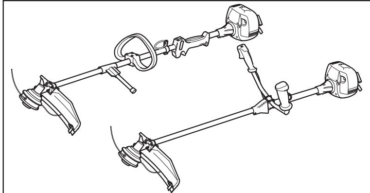
A. General description
1) ENGINE
12) SPARK PLUG
2) SHAFT
13) AIR FILTER
3) THROTTLE TRIGGER
14) FUEL TANK CAP
4) DECOMPRESSION VALVE
15) MUFFLER SHIELD
If not used properly this Petrol Brushcutter can be dangerous.
The warnings and safety instructions must be followed to ensure reasonable safety and efficiency in using this product. The operator is responsible for following the warnings and instructions in this manual and on the product.
Explanation of Symbols

Warning

Read the user instructions carefully o make sure you understand all the controls and what hey do.

Wear safety clothing: Approved safety glasses or face shield

Wear safety clothing: Approved safety helmet

Wear safety clothing: Approved ear defender

Wear safety clothing: Approved gloves

Wear safety clothing: Approved safety footwear

Do not smoke while refuelling or while operating the trimmer

Do not use metal blades

Maximum blade speed

Blade thrust

Maximum safety distance

Choke closed (cold start)
Beware of projected objects

Choke fully opened (hot start / run)
B. Safety precautions
1) Make sure all operators study this manual carefully before using the trimmer; only use this machine for usage specifically mentioned in this manual. Never allow children to use the trimmer.
2) When working with the trimmer wear suitable clothes: a) Close fitting protective clothes (do not wear short trousers or loose clothes). b) Safety shoes (do not wear sandals and do not work barefoot). c) Heavy-duty gloves. d) Safety face shield or goggles. Ensure you peel off the protective films, if existing, from the see - through plastic. e) Ear protection. f) Head protection when using circular saw blades. Make sure you know how to stop the engine in an emergency (see the section STARTING AND STOPPING ENGINE). Never use the trimmer when tired, physically indisposed or under the effect of alcohol, certain medicines or other drugs. Be careful of the rotating cutting attachment and hot surfaces on the unit.
3) Prolonged use of this product or other machines exposing the operator to vibration may produce Whitefinger's disease (Raynaud's Phenomenon). This may reduce the hands' ability to feel and regulate temperature and may produce general numbness. Continual or regular users should therefore monitor closely the condition of their hands or fingers. If any of the symptoms appear, seek immediate medical advice. Always hold the trimmer firmly with both hands. When working maintain a firm foothold. The trimmer must be used exclusively as recommended (see section SAFETY USAGE).
4) Do not carry the trimmer while the engine is running even for short distances; switch off the engine and carry the unit with the cutting head behind you. When carrying the trimmer in a vehicle, secure it to avoid fuel leakage. Always empty the fuel tank before transporting the unit. ATTENTION: For your safety the blade must be kept at all times in its prop
er case during transport and storage. Start the trimmer on a flat surface. When starting the unit, ensure you have a firm footing. Make sure the blade or the nylon string head does not touch the ground or any obstacle.
5) PRECAUTIONS AGAINST FIRE: do not operate the trimmer near fire or spilled petrol. Do not run the engine in closed or poorly ventilated areas. EXHAUST GASES ARE POISONOUS WHEN INHALED, THEY CAN CAUSE SUFFOCATION AND DEATH.
After refuelling always wipe off any spilled fuel. Do not smoke during this operation. Start the engine far away from the refuelling area and from fuel containers (minimum distance 3 meters). Do not refuel while the engine is still running.
6) Keep people and animals away from working area (minimum distance 15 meters). If somebody should approach you, turn the engine off and stop the blade or the rotating head (see chapter STARTING AND STOPPING THE ENGINE) as during operation the blade or the nylon string head might project grass, grit, or other debris. The blade is sharp, be careful even if handling it when the engine is off.
Wear heavy-duty gloves. Turn the engine off and wait for rotating parts to stop completely before working on the machine or before touching the blade or the string head above all to remove possible entangled material.
DO NOT USE THE MACHINE AT ALL IF THE SPECIFIED SAFETY GUARD IS NOT FIRMILY ATTACHED (see sections SAFETY USAGE and BLADES AND NYLON STRING HEAD ASSEMBLY).
Pay careful attention to safety recommendations as you might put your life or somebody else's in danger as a result of: a) possible contact with cutting or rotating parts. b) possibility of projection of various objects.
C. Safety usage
This product must be held to the right of the operator's body.
This will ensure exhaust fumes are directed away from the operator and will not be obstructed by the operator's clothing. If you have not used a trimmer before, spend some time in becoming familiar with the controls and method of usage before operation.
Check the machine carefully before using it.
Make sure that there are no loosened screws, damaged parts or fuel leakages.
Replace damaged or excessively worn accessories (blades, string heads, guards).
Ensure all maintenance or repair work is carried out by an authorised service center.
N.B. In order to maintain performance and safety, be sure to use original spare parts and accessories.
Avoid using the trimmer over excessively long periods of time.
Excessive amounts of vibration can be harmful.
1) Remove from the working area grit, debris, ropes, metal parts or any other object which might get entangled around the rotating parts or be dangerously projected.
Use only the correct accessory recommended for the type of vegetation to be cut. Do not let the rotating blade contact any foreign object such as stones, rocks, cans etc.
Secure hair to keep it above shoulder height. Before starting to work fit the harness. Adjust harness with the buckle so that the trimmer is well balanced on your right side and the blade or string head is parallel to the ground. Always maintain a firm foothold and a good balance while using the machine. Do not move backwards while you work as obstacles may not be visible.
The fitting of the safety pole barrier is obligatory on units equipped with a delta shaped handle when used with a metal blade.
The purpose of this safety pole barrier is to maintain a safe distance between the metal blade and the user under all normal or exceptional circumstances.
2) Harness ring (B) must never be moved from its original position to avoid unbalancing the unit.
Front handles can be separately adjusted to make usage easier on units fitted with "U" shaped handles.
3) The following accessories can be assembled to your trimmer: a) blade, b) nylon string head.
Do not attach any blade to a unit without proper installation of all required parts. Failure to use the proper parts can cause the blade to fly off and seriously injure the operator and/or bystanders.
a) WHEN USING A BLADE ENSURE THE COR
RECT GUARD IS FITTED.
b) WHEN USING A NYLON STRING HEAD ENSURE THE CORRECT GUARD IS FITTED.
When using the unit always hold the front part of the machine (blade or nylon string head) below your waist.
NYLON STRING HEAD:
Always make sure it has been correctly assembled and fitted.
The nylon head is suitable to cut grass and weeds wherever there might be obstacles like trees, fences or walls.
The nylon string head also reduces the likelihood of damaging small plants and trees bark.
Only use flexible, nonfilament nylon line in the nylon line head as specified by the manufacturer. Never use metallic line which could break off and become a dangerous projectile.
BLADE:
Always make sure it has been correctly fitted.
When fitting or changing a cutting device, ensure you follow the instructions in the section "Blade or nylon string head assembly" with extreme precision. Fit these cutting devices using all and only the parts as described, and in the correct order.
4) BLADES: you can cut any type of grass, brushwood or shrub.
Operate the machine like a sickle always cutting at full throttle.
5) WARNING: always use a well sharpened blade.
A blade with worn teeth besides providing poor performance might also generate a sudden thrust. This can result in a violent sideways kick caused when the blade touches against wood or solid bodies, such thrust might then cause the operator to loose control of the machine itself. Never attempt to work with a damaged blade but replace it with a new one.
THrust: can occur when using any type of circular blade within the risk area: therefore it is advisable to cut using the remaining area of the blade.
CIRCULAR SAW BLADE: it can be used to cut sappling, small trees with a diameter up to 7 cm., to clean shrubs.
WARNING: IF A METAL 24-80 TOOTH BLADE (A SAW TOOTH BLADE) IS USED A DOUBLE SHOULDER HARNES AND A SAFETY GUARD (PROTECTION) MUST ALSO BE USED AS MARKED IN THE SUMMARY CHART (SEE CLOTHES SECTION IN SAFETY CHAPTER: ALWAYS WEAR A HELMET).
ALWAYS USE GENUINE ACCESSORIES AND SPARE PARTS AVAILABLE FROM AUTHORISED SERVICING DEALERS. THE USE OF
D. Fuel mix
Do not use any other type of fuel than the type recommended in this manual.
This product is equipped with a two-stroke engine and must therefore use a mixture of lead-free gasoline (with a minimum of 90 octanes) and fully synthetic oil for two-stroke engines, specific for lead-free gasoline in the proportions indicated in the table on the cover page at item (D).
IMPORTANT! Read the oil specifications on the can carefully: the use of oil lacking the specifications indicated in this manual can cause severe damage to the engine!
To obtain the best mixture, pour the oil first, followed by the gasoline, into an approved container, shake well (repeat the operation every time you draw any fuel from the container).
The characteristics of the mixture are subject to aging and may be altered in time, so we recommend mixing only the amount strictly needed for use. If you use a mixture that is several weeks old, this could damage the engine.
WARNING
Do not smoke when re-fuelling.
Always open the fuel cap slowly, to release any pressure build up in the tank.
Re-fuel in open spaces only, keeping away from naked flames or sparks.
SAFE STORAGE OF FUEL
Petrol fuel mix is highly inflammable.
Put out all cigarettes, pipes and cigars before working with fuel.
Avoid spilling fuel. Store fuel in a cool, well ventilated place, in an approved container specifically designed for the purpose.
Never store engine with fuel in the tank in enclosed, poorly ventilated areas where fuel fumes may reach an open flame, spark or pilot light such as in a furnace, water heater, clothes dryer etc. Petrol fumes can cause an explosion or a fire. Never store large amounts of fuel.
To prevent possible restarting problems avoid running the fuel tank dry.
This also helps to extend engine life.
E. Safety guard assembly
1) In the interest of safety, it is imperative that the unit is used with the correct guard (P/N 248959 Ø25 P/N 248960 Ø30) when using any blade or a nylon string head, except the 24-80 tooth blade. Line cutter blade (L): assemble as illustrated E1.
2-3) When using a saw tooth blade (optional accessory), the correct guard must be fitted (P/N 240553).
A double shoulder harness must also be worn.
Only use blades or nylon string heads clearly marked with a maximum speed of at least 10,500 min ^-1 .
Follow the fitting instructions carefully.
N.B: Saw tooth blades (24 - 80 tooth) have a central base diameter of 20mm and therefore require the use of the appropriate size top flange to ensure a correct fit. The part number is detailed in the cutting attachment summary chart.
F. Blade and nylon string head assembly
Assemble the correct guard to suit the kind of blade or nylon string head to be used (See section: SAFETY GUARD ASSEMBLY).
1) Assemble blade as illustrated:
a) Flange guard - b) Upper cap with blade centering - c) Blade with text and directional arrow facing upwards - d) Lower washer - e) Fixed mower gauge - f) Blade locking screw (length mm 16).
2) If you want to assemble the rotating mower gauge, proceed as illustrated:
a) Flange guard - b) Upper cap with blade centering - c) Blade with text and directional
arrow facing upwards - d) Lower washer - e) Spacer - f) Rotating mower gauge - g) Blade locking screw (length mm 34,5).
Replace the blade attachment bolt if damaged in any way.
3) Make sure that the blade bore opening fits perfectly around the centering collar on the upper cap.
Tighten counterclockwise.
While tightening, the blade assembly can be held fast by inserting the wrench or the screwdriver supplied into the cap and gearcase holes.
To do this, rotate the cap intil the two holes coincide.
4) Assemble nylon string head as illustrated: a) Flange guard - b) Upper cap - c) Guard d) Nylon string head
Tighten counterclockwise.
5) While tightening, the head assembly can be held fast by inserting the wrench or the screwdriver supplied into the holes as already shown for blade assembly.
WARNING: Do not use the guard for the nylon string head when using a metal blade.
G. Engine/shaft assembly
DANGER. Do not run engine without shaft attached as clutch could fly off.
1) Assemble the engine onto the shaft. Make sure the shaft is fully and correctly engaged up to the shank, then tighten the 2 screws (A) in a criss-cross sequence.
2) Fit the end of the trigger cable connector (B) into the slot on swivel (C).
3) Adjust the screw (D) of the trigger cable connector so that the cable can easily slide in the opening with a play of 1 mm before operating the swivel (C).
Tighten now the hexagonal nut (E).
4A) Stop switch (STOP) cable: fit the connection.
4B) Earth lead: connect as illustrated.
H. Handle assembly
1) DOUBLE HANDLE
Handle (A) can be adjusted for individual operator comfort by swivelling it forwards or backwards. To do this, loosen button (C), position the handle for maximum comfort, then tighten button (C) securely. Clip the suspension harness hook into one of the 5 holes on the top side of the shaft support to achieve the best balance according to the type of work to be undertaken.
NB: Handle assembly (A) can be folded parallel to the shaft to facilitate transportation or storage. To do this, loosen knob (C), twist support (B) 90^ in a clockwise direction, fold the handle (A) into the required position and then tighten knob (C).
2) DELTA FRONT HANDLE
Secure the handle in front of the label placed on the shaft 11 cm from the rear grip when assembling nylon string head and 36 cm when assembling metallic blades. This position ensures optimum balance and safety. The handle must be perpendicular to the shaft as illustrated (Fig.2). The handle bar must be mounted using all the items supplied and in the exact configuration shown in figures 1 or 2.
3) DOUBLE HANDLE
Adjust and secure double hand clamp by tightening the screws.
I. Starting and stopping the engine
WARNING: Before using the product every user should carefully read the sections SAFETY, SAFETY USAGE and SYMBOL MEANINGS.
STARTING A COLD ENGINE
1) Position the on/off switch to the I (ON) position, away from the «STOP» position.
2) Rotate the choke lever in the direction illustrated by the arrows. This engages the fast idle system.
3) Squeeze the primer bulb (C) several times until you see fuel begin to return back through the tube (D) towards the fuel tank. Push the decompression valve (B)
down if your models is fitted with one. Pull the starter handle until the engine starts.
4) Hold the machine safely and allow the engine to run for a few seconds. Grip the control handle firmly, pushing down on the safety trigger (S) and then squeezing the accelerator trigger (A). This action automatically releases the spring loaded choke lever (E) disengaging the fast idle system.
WARNING: The fast idle system does cause the cutting attachment to rotate when engaged.
STARTING A WARM ENGINE
Position the on/off switch to the I (ON) position. Squeeze the primer bulb (C) several times until you see fuel begin to return back through tube (D) to the fuel tank. Push the decompression valve (B) down if your model is fitted with one. Pull the starter handle until the engine runs.
5) STOPPING THE ENGINE
Push the on/off switch to the STOP position.
WARNING: After the engine has been
switched off, the rotating cutting attachment, blade or string head, will continue to rotate for a few seconds due to their inertia. Continue to hold the machine firmly off the ground until it stops completely. Keep your hands away whilst it is moving.
N.B. In an emergency, the cutting attachment can be stopped quickly by touching it parallel to the ground after moving the switch to the «STOP» position.
L. Carburettor adjustment
To adjust the idle speed, however, proceed as follows:
With engine running and warm, slowly turn screw 'T' clockwise until the engine runs smoothly with a consistent noise level but without making the cutting head rotate.
If the cutting attachment does move or the engine runs too fast, slowly turn screw 'T' in an anticlockwise direction until the correct speed is obtained.
Precise numerical engine speed settings are mentioned in the technical detail chart in the front of the owner's manual.
M. Regular maintenance
From time to time ensure all screws are tight. Replace damaged, worn, cracked or warped blades. Always make sure nylon string head or blade have been assembled correctly (see sections NYLON STRING HEAD and BLADE ASSEMBLY) and blade fastener is tightened.
1) AIR FILTER CLEANING
(at least every 25 working hours).
A dust clogged air filter may cause carburetor problems.
This may prevent the engine from reaching its maximum speed and cause high fuel consumption and/or difficult starting.
Remove filter cover as shown in figure 1. Carefully clean the inside of filter box. The filter can also be cleaned with compressed air.
N.B. Slide the air filter back into its location (C) ensuring the tabs (A) are pointing downwards as illustrated, ensure it clicks firmly into its airtight position.
2) Every 50 working hours inject the gearcase with gear grease under high pressure through hole (C).
3) SPARK PLUG
From time to time (at least every 50 hours) remove and clean the spark plug and check the electrode gap (0,5 / 0,6mm) .Replace spark plug about every 100 working hours or whenever it is extremely encrusted. Heavily encrusted electrodes can result from wrong fuel mixture (too much oil in the petrol) or a poor quality of oil in the fuel mix. Check and correct.
4) FUEL FILTER
To change fuel filter remove the tank cap and pull out the filter with a piece of bent wire or long forceps. Contact your Service Station for general servicing and cleaning of internal parts at least once a year. This will reduce the possibility of unexpected problems and will ensure maximum product life and efficiency.
REGULARLY: it is important, in order to avoid engine overheating, to remove dust and dirt from slots, gaps and from in between cylinder fins using a wooden scraper.
LONG STORAGE: empty fuel tank and run engine until dry.
Store trimmer in a dry place.
N. Replacing nylon line
1) Loosen the locking nut on the base of the nylon head by turning it clockwise.
2) Remove the base cover assembly. Remove the empty spool from the housing and discard any remaining line.
REWINDING NEW LINE
3) Prepare 2 lengths (8ft each) of 2.4mm nylon line. Thread 1 end of each line into the two holes on opposite sides of the spool. Pinch the exposed ends flat with a pair of pliers to prevent them slipping through the hole.
4) Wind the two lines in the same direction around the spool.
REASSEMBLY
5) Slide the end of the two lines into the grooves to hold the line temporarily.
6) Position the spool back into the housing and pull the line through the eyelets.
7) Pull about 12cm (5ins) of line out on either side.
8) Reassemble the nylon string head as illustrated; mower gauge,spring and locking nut (tighten in an anti-clockwise direction).
9) N.B: In order to extend the nylon line as it wears down, pull the mower gauge downwards and turn it in a clockwise direction to feed out the desired length of line.
O. Ecology
This chapter is about how to maintain the "eco features" of the machine as originally developed by our engineers, the correct use of this machine and handling of waste oil and fuel.
- Research on the 4 stroke engine has been developed in order to produce lower fuel consumption and low emission of polluting exhaust gases
- Use of the machinery: During the fuel filling operation particular care should be taken to avoid
waste fuel polluting the enviroment.
- When storing for a long period, empty fuel tank and run engine until dry, observing the same precautions as when filling.
- Disposal of machines: Old machines can be very dangerous for the environment - do not throw them away!! Please apply to the competent body authorised to collect industrial waste. As prescribed by National laws on enviroment
Technical data
| DISPLACEMENT (cm3) | 34 | 38 | 42 | 46 |
| BORE AND STROKE (mm) | 38x30 | 40x30 | 41x32 | 43x32 |
| ENGINE OUTPUT (Kw) | 1,2 | 1,3 | 1,6 | 1,8 |
| ENGINE SPEED AT MAX POWER (min-1) | 8.000 | 8.000 | 8.000 | 8.200 |
| MAXIMUM SPEED, NO LOAD (min-1) | 10.000 | 10.000 | 10.000 | 11.000 |
| MINIMUM SPEED (min-1) | 2.800 | 2.800 | 2.800 | 2.800 |
| BLADE SHAFT SPEED (min-1) | 7.700 | 7.700 | 7.700 | 8.500 |
| BLADE LOCKING NUT TIGHTENING TORQUE (Nm) | 17 | 17 | 17 | 17 |
| DRY WEIGHT (kg) | 7,1 | 7,3-8,3 PRO | 7,4-8,4 PRO-8,8 BP | 7,7-8,7 PRO-10,8 BP |
| FUEL TANK CAPACITY (cm3) | 900 | 900 | 900 | 900 |
| SOUND PRESSURE LEVEL (AT THE OPERATOR'S EAR) LpAav (dBA) (ISO7917) | 97 | 97 | 97 | 106 |
| GUARANTEED NOISE LEVEL LwAav (dBA) (ISO 10884) | 114 | 114 | 114 | 114 |
| MEASURED SOUND POWER LEVEL LwAav (dBA) (ISO 10884) | 113 | 113 | 113 | 113 |
| VIBRATIONS LEVEL STRING HEAD (ISO 7916) (m/s2) MAX-MIN | 8,2-1,6 | 8,2-1,7 | 10,55-1,8 | 12,5-1,06 |
| VIBRATIONS LEVEL BLADE (ISO 7916) (m/s2) MAX-MIN | 8,2-1,6 | 8,2-1,7 | 16,38-1,8 | 17,79-1,06 |
Fault finding table
| Engine will not start | Engine runs badly or looses power when cutting | The machine runs but does not cut well | |
| Check STOP switch is in the position I. | ● | ||
| Control fuel level min. 25% tank capacity. | ● | ● | |
| Check air filter is clean. | ● | ● | |
| Remove spark plug, dry it, clean it and adjust it, and replace it, if necessary. | ● | ● | |
| Change fuel filter. Contact your dealer. | ● | ||
| Carefully follow the cutting accessory assembly instructions. | ● | ||
| Check metal cutting accessory is sharp. Otherwise, contact your dealer. | ● |
Engine still gives trouble: contact your dealer.
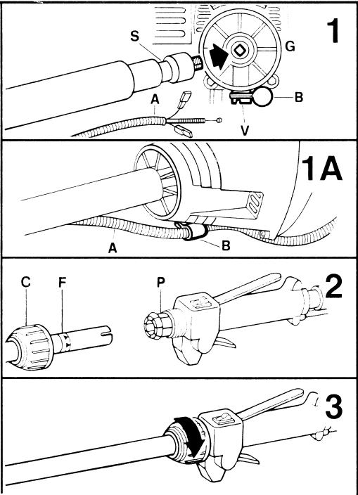
1 Insert the flexible drive shaft onto the engine connector (G). Ensure the male square end of the shaft engaged firmly into the female square end of the connector. Insert throttle cable and electrical wires (A) into the retaining guide (B) far enough to allow the necessary connections to be made (see Fig. 1A).
Tighten screw (V) ensuring it locates correctly into its opening (S) . Now the shaft is firmly fixed in the connector.
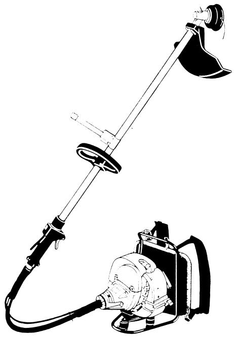
DE MOTORSENSE - RÜCKENGERÄT
2 Pull the plastic ring nut (C) away from the end of the rigid tube turning it counterclockwise if necessary. Insert the rigid tube into the handle section until the label (F) is aligned with the edge of the plastic threaded rim (P). These procedures will ensure a correct fit between both male and female connectors.
3 Tighten the ring nut (C) hand tight. Follow the standard instructions mentioned earlier in this manual to connect the throttle cable and electric wires.