
E3X-DAC-S - Fiber Optic Sensor OMRON - Free user manual and instructions
Find the device manual for free E3X-DAC-S OMRON in PDF.


| Product Type | Color Fiber Sensor |
| Brand | OMRON |
| Model | E3X-DAC-S (standard or advanced) |
| Amplifier Width | 10 mm |
| Weight (cable model) | Approximately 100 g |
| Weight (connector model) | Approximately 55 g |
| Power Supply | 12 to 24 VDC ±10% |
| Power Consumption | 960 mW max (40 mA max at 24 VDC) |
| Control Output | NPN or PNP open collector, 50 mA max |
| Light Source | White LED (420 to 700 nm) |
| Detection Method | Mode C (RGB ratio), Mode I (intensity), Mode Black (total intensity) |
| Number of Stored Colors | 1 (standard) or 2 (simultaneous, advanced model) |
| Response Time | From 60 µs (super high speed) to 4 ms (high resolution) |
| Timer Functions | OFF delay, ON delay, one-shot (1 ms to 5 s) |
| Display | Dual 7-segment display (main red, secondary green), reversible orientation |
| Remote Control Input | Advanced models: teaching, reset, off |
| Protection | Polarity reversal, output short-circuit, output polarity protection |
| Ambient Operating Temperature | -25 to 55 °C (depending on number of connected units) |
| Ambient Humidity | 35 to 85% (without condensation) |
| Protection Degree | IP50 (with protective cover) |
| Housing Materials | Polybutylene terephthalate (PBT) for housing, polycarbonate (PC) for cover |
| Included Accessories | Instruction manual |
| Optional Accessories | Master/slave connectors (E3X-CN11/12), mounting bracket (E39-L143), end plate (PFP-M) |
| Maintenance | Keep protective cover in place; do not use in environments with water, oils, or chemicals; do not disassemble |
| Repairability | Amplifier separately replaceable if instability occurs; fibers sold separately |
Frequently Asked Questions - E3X-DAC-S OMRON
User questions about E3X-DAC-S OMRON
0 question about this device. Answer the ones you know or ask your own.
Ask a new question about this device
Download the instructions for your Fiber Optic Sensor in PDF format for free! Find your manual E3X-DAC-S - OMRON and take your electronic device back in hand. On this page are published all the documents necessary for the use of your device. E3X-DAC-S by OMRON.
USER MANUAL E3X-DAC-S OMRON
The Fiber Sensor That Sees in Color
Easy and Reliable ... Featuring a Color-sensing Engine
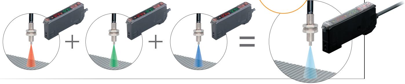
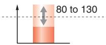
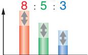
The color-sensing engine uses three parameters, RGB, to process incident light. It detects color information from the workpiece for precise detection of color differences.
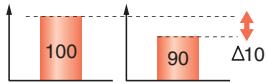
Intensity Detection (Conventional Type)
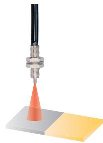
Unstable...
Color Detection (Color Sensing Type)
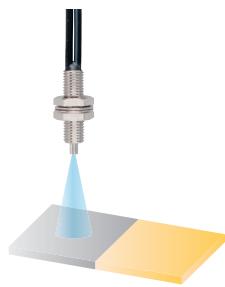
Incident light intensity
RGB ratio
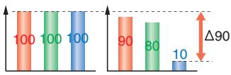
Precise Detection
Color VS. Detection Capability
A high-power white LED and a multi-RGB processing system combine to cover all RGB wavelengths, enabling easy and accurate detection of workpieces without having to use a different light source to match each one.
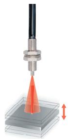
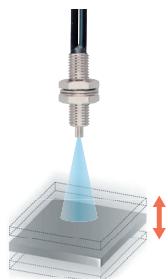
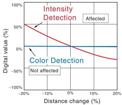
Changes in the three parameters are processed as a ratio, so they are not affected by light-intensity variations due to workpiece movement.
Intensity Detection (Conventional Type)
Misdetec-tion...

Color Detection (Color Sensing Type)
Incident light intensity
RGB ratio
Resists Movement
Thinnest in the Industry
A Slim, 10-mm-wide Amplifier Unit
Use of a white LED and a one-package RGB light-receiving element has made it possible to unify the Amplifier Unit, both in size and operation, with conventional models. If detection should become unstable, the Amplifier Unit can be separately replaced to immediately regain stability.
Easy and Reliable ... Ease of Use and Smart Functions
In addition to ensuring easy use, we have added a number of smart functions, such as remote control to simplify setup, and twin sensing and output to simultaneously distinguish two registered colors. (advanced models)
Reliable
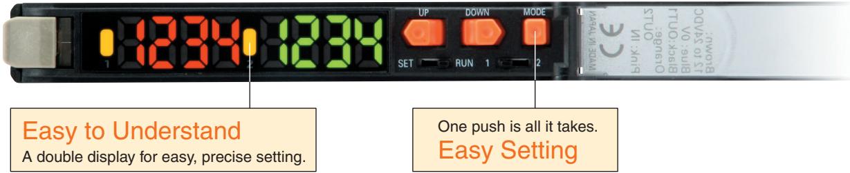
Setting guide function.
First in Its Class
This function guides the user to ensure that the workpiece is in an appropriate position for teaching. (Indicates OVER, OK, or LOW.)
Easy and Reliable ... Simplified Wiring Connector Reduces Work Steps
OMRON's unique simplified wiring connectors provide the power for each added Sensor. Up to 16 Units can be mounted, including a combination of Digital Fiber Sensors and other simplified wiring connector products such as Digital Laser Sensors.
Power is supplied through the connector, so only one output wire is required. (For adding Sensors)
From left to right
Digital Fiber Sensors: E3X-NA
E3X-DA-S/MDA
E3X-DAC-S
Digital Laser Sensor: E3C-LDA
Proximity Sensor: E2C-EDA
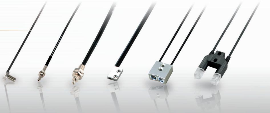
Wide Range of Fiber Heads Available
Select from a wide range of Fiber Heads to match the workpiece and working space. This makes installation possible even in small spaces.
Easy and Reliable Applications (Examples)
Detecting Marks
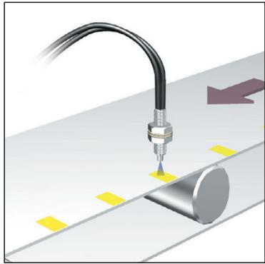
Because it distinguishes RGB ratios, detection is highly resistant to workpiece movement.
Distinguishing Semi-transparent Objects
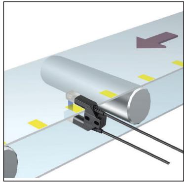
Through-beam Fiber Heads are capable of detecting color differences in semi-transparent objects.
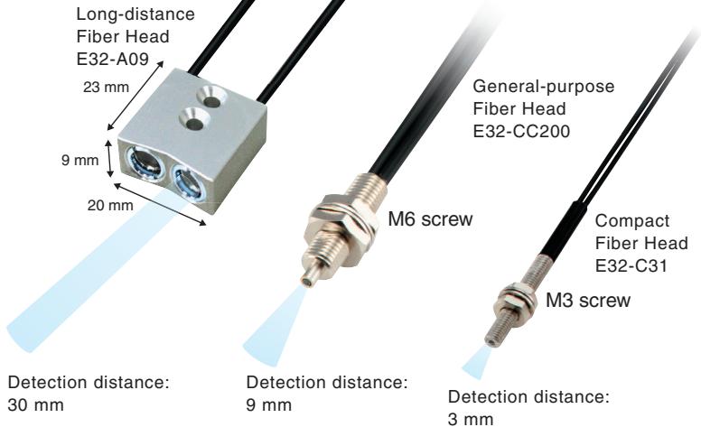
Many Compact Heads
Detecting Black Marks
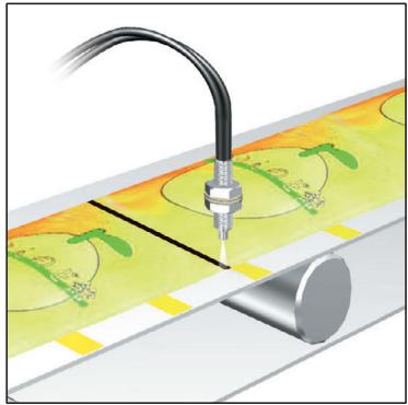
In Black Mode, black seam tape and other black marks can be detected regardless of film color or patterns.
Distinguishing Trays
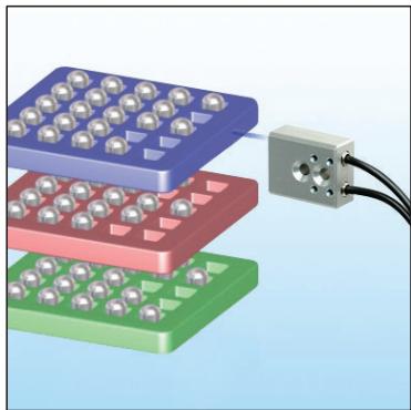
Twin sensing and remote control functions simplify setup.
Detecting Wafers
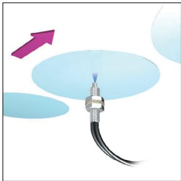
Workpieces that absorb a specific wavelength can be detected with a wide range of wavelengths.
Detecting Products on Conveyors
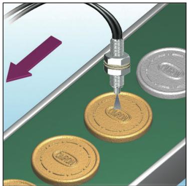
If you teach the conveyor (i.e., the background), you can detect workpieces even if they have different colors, shapes, or gloss.
Ordering Information
Amplifier Units with Cables
Amplifier Units
| Item | Appearance | Functions | Model | |
| NPN output | PNP output | |||
| Standard models | Timer, Response speed change | E3X-DAC11-S 2M | E3X-DAC41-S 2M | |
| Advanced models | Standard models + Simultaneous determination (2 colors) AND/OR output, Remote setting | E3X-DAC21-S 2M | E3X-DAC51-S 2M | |
Amplifier Units with Connectors (Amplifier Unit Connectors must be purchased separately.)
| Item | Appearance | Functions | Model | |
| NPN output | PNP output | |||
| Standard models | Timer, Response speed change | E3X-DAC6-S | E3X-DAC8-S | |
Amplifier Unit Connectors (Order Separately) Note: Protector seals are provided as accessories.
| Item | Appearance | Cable length | No. of conductors | Model |
| Master Connector | 2 m | 3 | E3X-CN11 | |
| Slave Connector | 1 | E3X-CN12 |
Combining Amplifier Units and Connectors
Amplifier Units and Connectors are sold separately. Refer to the following tables when placing an order.
| Amplifier Unit | ||
| Model | NPN output | PNP output |
| Standard models | E3X-DAC6-S | E3X-DAC8-S |
When Using 5 Amplifier Units
| Applicable Connector (Order Separately) | |
| Master Connector | Slave Connector |
| E3X-CN11 | E3X-CN12 |
Amplifier Units (5 Units)
- 1 Master Connector 4 Slave Connectors
Mounting Bracket
Accessories (Order Separately)
| Appearance | Model | Quantity |
| E39-L143 | 1 |
End Plate
| Appearance | Model | Quantity |
| PFP-M | 1 |
Amplifier Units
| Item | Type Model | Standard models | Advanced models |
| E3X-DAC□-S□ (□: 11/41/6/8) | E3X-DAC□-S□ (□: 21/51) | ||
| Sensing distance | Depends on the Fiber Unit. Refer to pages 8 to 10. | ||
| Sensing object | Reflective models: Standard 11 color cards (See note 1.), Through-beam models: Opaque or trans-lucent object | ||
| Light source (wavelength) | White LED (420 to 700 nm) | ||
| Sensing method | C Mode: RGB ratio determination (or I Mode: Light intensity determination for red, green, or blue, Black Mode: Determination of total light intensity for red, green, and blue) (See note 2.) | ||
| Number of registered colors | 1 | 2 (simultaneous determination) | |
| Power supply voltage | 12 to 24 VDC ±10%, ripple (p-p) 10% max. | ||
| Power consumption | 960 mW max. (current consumption: 40 mA max. at power supply voltage of 24 VDC) | ||
| Control output | NPN or PNP open collector Load power supply voltage: 26.4 VDC max. Load current: 50 mA max. (residual voltage: 2 V max.) | ||
| Remote control input | --- | No-voltage input (contact/transistor) (See note 3.) | |
| Protection circuits | Reverse polarity for power supply connection, output short-circuit, Reversed output polarity protec-tion | ||
| Re-sponse time | Super-high-speed mode (See note 4.) | Operate or reset: 60 μs | Operate or reset: 120 μs |
| High-speed mode | Operate or reset: 300 μs | Operate or reset: 600 μs | |
| Standard mode | Operate or reset: 1 ms | Operate or reset: 2 ms | |
| High-resolution mode | Operate or reset: 4 ms | Operate or reset: 8 ms | |
| Sensitivity setting (color registration, allowable range) | Teaching (one-point teaching or teaching with/without workpiece) or manual adjustment | ||
| Func-tions | Operating mode | ON for match (ON for same color as registered color) or ON for mismatch (ON for different color from registered color) | |
| Timer function | Timer type: OFF delay, ON delay, or one-short Timer time: 1 ms to 5 s (variable) | ||
| Control outputs | --- | Output for each channel, AND output, and OR output | |
| Remote control | --- | One-point teaching, teaching with/without work-piece, zero reset, and light emission OFF | |
| Display switch (See note 5.) | Seven patterns total: Match + Threshold, Margin + Threshold, Analog bar display, Peak + Bottom, etc. | ||
| Initialization | Initial reset (factory defaults) or user reset (saved settings) | ||
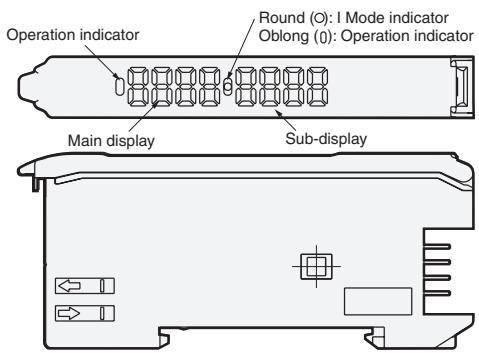
| Display | Operation indicator (orange)/I mode display indicator (orange) | Channel 1 and channel 2 operation indicators (orange) | |
| Digital display | 7-segment displays (Main display: Red, Sub-display: Green), display direction can be reversed. | ||
| Ambient illumination (Receiver side) | Incandescent lamp: 3,000 luxSunlight: 10,000 lux | ||
| Ambient temperature range (See note 6.) | Operating: -25°C to 55°CStorage: -30°C to 70°C (with no icing or condensation) | ||
| Ambient humidity range | Operating and storage: 35% to 85% (with no condensation) | ||
| Insulation resistance | 20 MΩ min. (at 500 VDC) | ||
| Dielectric strength | 1,000 VAC at 50/60 Hz for 1 minute | ||
| Vibration resistance | Destruction: 10 to 50 Hz with a 1.5-mm double amplitude for 2 hrs each in X, Y and Z directions | ||
| Shock resistance | Destruction: 500 m/s², for 3 times each in X, Y and Z directions | ||
| Degree of protection | IEC 60529 IP50 (with Protective Cover attached) | ||
| Connection method | Pre-wired or Amplifier Unit Connector (Units con-nected: 16 max.) | Pre-wired | |
| Weight (packed state) | Pre-wired model: Approx. 100 g, Amplifier unit connector model: Approx. 55 g | ||
| Materi-als | Case | Polybutylene terephthalate (PBT) | |
| Cover | Polycarbonate (PC) | ||
| Accessories | Instruction manual | ||
Note:1. Sensing Object: Standard Color Card (230 Colors) from Japan Color Enterprise Co., Ltd.)
| Color (11 standard colors) | Munsell color notation |
| White | N9.5 |
| Red | 4R 4.5/12.0 |
| Yellow/red | 4YR 6.0/11.5 |
| Yellow | 5Y 8.5/11.0 |
| Yellow/green | 3GY 6.5/10.0 |
| Green | 3G 6.5/9.0 |
| Blue/green | 5BG 4.5/10.0 |
| Blue | 3PB 5.0/10.0 |
| Blue/purple | 9PB 5.0/10.0 |
| Purple | 7P 5.0/10.0 |
| Red/purple | 6RP 4.5/12.5 |
| Black | (N2.0) |
-
When teaching with/without a workpiece, the best sensing method will be automatically selected (RGB ratio (C Mode) or light intensity determination (I Mode)). If color differences are not strong enough and RGB ratios would result in unstable detection, then light intensity determination (I Mode) will be selected. The detection mode can also be set to C, I, or Black Mode.
-
Input Specifications
| Contact input(relay or switch) | Non-contact input(transistor) | |
| NPN | ON: Shorted to 0 V (sourcing current: 1 mA max.).OFF: Open or shorted to Vcc. | ON: 1.5 V max. (sourcing cur-rent: 1 mA max.)OFF: Vcc - 1.5 V to Vcc (leakage current: 0.1 mA max.) |
| PNP | ON: Shorted to Vcc (sinking current: 3 mA max.).OFF: Open or shorted to 0 V. | ON: Vcc - 1.5 V to Vcc (sinking current: 3 mA max.)OFF: 1.5 V max. (leakage cur-rent: 0.1 mA max.) |
- Mutual interference prevention cannot be used in super-high-speed mode, and light intensity determination (I Mode) must be used.
- With light intensity determination (I Mode), the correlation is not displayed, but rather the light intensity is displayed.
- The allowable ambient operating temperature changes according to the number of Units that are linked.
2 Units: -25 to 55^ , 3 to 10 Units: -25 to 50^ , and 11 to 16 Units: -25 to 45^
Amplifier Unit Connectors
| Item | Model | E3X-CN11 | E3X-CN12 |
| Rated current | 2.5 A | ||
| Rated voltage | 50 V | ||
| Contact resistance | 20 mΩ max. (20 mVDC max., 100 mA max.) (The figure is for connection to the Amplifier Unit and the adjacent Connector. It does not include the conductor resistance of the cable.) | ||
| No. of insertions | Destruction: 50 times (The figure for the number of insertions is for connection to the Amplifier Unit and the adjacent Connector.) | ||
| Materials | Housing | Polybutylene terephthalate (PBT) | |
| Contacts | Phosphor bronze/gold-plated nickel | ||
| Weight (packed state) | Approx. 55 g | Approx. 25 g | |
Sensing Distance
Reflective Models
(Unit: mm)
| Type | Sensing object | White paper | Standard color card (11 colors) (mutual determination) | ||||||||
| High-resolution mode | Standard mode | High-speed mode | Super-high-speed mode | High-resolution mode | Standard mode | High-speed mode | Super-high-speed mode | ||||
| Standard models | General-purpose | E32-DC200 | 70 | 54 | 46 | 18 | 14 | 10 | 8.5 | 6 | |
| E32-D11R/E32-D12R/E32-D15XR/E32-D11N/E32-DC200BR (B4R) | 42 | 32 | 26 | 11 | 8.5 | 6 | 5 | 3.5 | |||
| E32-D14LR | 11 | 8.5 | 7 | 2.5 | 2.4 | 1.7 | 1.4 | 1 | |||
| E32-D15YR/E32-D15ZR | 10 | 7.5 | 6.5 | 2.5 | 2.1 | 1.5 | 1.3 | 0.9 | |||
| E32-D211/E32-DC200E/E32-D22/E32-D25X/E32-DC200F (F4) | 20 | 16 | 14 | 5 | 4.5 | 3 | 2.5 | 1.5 | |||
| E32-D24 | 8.8 | 6.7 | 5.8 | 2.1 | 1.8 | 1.3 | 1.1 | 0.7 | |||
| E32-D25Y/E32-D25Z | 5.8 | 4.5 | 3.8 | 1.4 | 1.2 | 0.9 | 0.7 | 0.5 | |||
| Break-resistant | E32-D11/E32-D15XB | 42 | 32 | 26 | 11 | 8.5 | 6 | 5 | 3.5 | ||
| E32-D21B/E32-D221B | 19 | 15 | 13 | 4.5 | 4.1 | 3 | 2.4 | 1.5 | |||
| E32-D21/E32-D22B | 8.8 | 6.7 | 5.8 | 2.1 | 1.8 | 1.3 | 1.1 | 0.7 | |||
| E32-D25XB | 14 | 10 | 9 | 3 | 3 | 2.1 | 1.7 | 1.1 | |||
| Fluorine coating | E32-D11U | 42 | 32 | 26 | 11 | 8.5 | 6 | 5 | 3.5 | ||
| Special-beam models | Long-distance, high power | E32-A09 | 20 to 38 | 24 to 36 | 26 to 32 | --- | 20 to 38 | 24 to 36 | 26 to 32 | --- | |
| E32-D11L | 90 | 70 | 60 | 22 | 19 | 13 | 11 | 7.5 | |||
| E32-D21L/E32-D22L | 35 | 26 | 22 | 8 | 7 | 5 | 4 | 2.5 | |||
| Coaxial | E32-CC200 | 60 | 45 | 35 | 16 | 12 | 9 | 7 | 4 | ||
| E32-CC200R/E32-C11N | 35 | 26 | 22 | 9 | 7.5 | 5 | 4.5 | 3 | |||
| E32-D32L | 35 | 26 | 22 | 9 | 7.5 | 5 | 4.5 | 3 | |||
| E32-C31/E32-D32 | 17 | 13 | 11 | 4.5 | 3.7 | 2.7 | 2.2 | 1.5 | |||
| E32-C31N | 7.7 | 6 | 4.8 | 2.1 | 1.6 | 1.2 | 0.9 | 0.7 | |||
| Area sensing | E32-D36P1 | 35 | 26 | 22 | 9 | 7.5 | 5 | 4.5 | 3 | ||
| Environment resistive models | Heat-resistant | E32-D51 | 55 | 42 | 36 | 14 | 11 | 8.5 | 7 | 4.5 | |
| E32-D81R-S/E32-D61-S | 20 | 15 | 13 | 5 | 4 | 3 | 2.5 | 1.5 | |||
| E32-D73-S | 13 | 10 | 8.5 | 3.5 | 2.8 | 2 | 1.7 | 1.2 | |||
| Chemical resistant | E32-D12F | 22 | 17 | 15 | 6 | 4.9 | 3.5 | 2.9 | 2 | ||
| E32-D14F | 9 | 7 | 6 | 2 | 2.1 | 1.4 | 1.2 | 0.6 | |||
Through-beam Models
(Unit: mm)
| Sensing object | Opaque object | Translucent object (See note.) | ||||||||
| Type | High-resolution mode | Standard mode | High-speed mode | Super-high-speed mode | High-resolution mode | Standard mode | High-speed mode | Super-high-speed mode | ||
| Standard models | General-purpose | E32-TC200 | 200 | 160 | 140 | 70 | 45 | 32 | 26 | 22 |
| E32-T11R/E32-T12R/E32-T15XR/E32-T11N/E32-TC200BR (B4R) | 150 | 110 | 95 | 50 | 30 | 22 | 18 | 16 | ||
| E32-T14LR/E32-T15YR/E32-T15ZR | 55 | 44 | 38 | 19 | 12 | 8.5 | 7 | 6.5 | ||
| E32-TC200E/E32-T22/E32-T222/E32-T25X/E32-TC200F (F4) | 80 | 60 | 50 | 46 | 17 | 12 | 10 | 7 | ||
| E32-T24/E32-T25Y/E32-T25Z | 48 | 36 | 32 | 26 | 10 | 7 | 6 | 4 | ||
| Break-resistant | E32-T11/E32-T12B/E32-T15XB | 190 | 140 | 120 | 60 | 40 | 28 | 24 | 20 | |
| E32-T21/E32-T221B/E32-T22B | 70 | 55 | 48 | 40 | 15 | 11 | 9 | 6 | ||
| E32-T25XB | 55 | 42 | 36 | 30 | 11 | 8 | 7 | 4.5 | ||
| Fluorine coating | E32-T11U | 190 | 140 | 120 | 60 | 40 | 28 | 24 | 20 | |
| Special-beam models | Long-distance, high power | E32-T17L | 4300 | 3200 | 2800 | 1400 | 900 | 600 | 500 | 460 |
| E32-TC200+E39-F1 | 1100 | 850 | 700 | 360 | 220 | 160 | 140 | 120 | ||
| E32-T11R+E39-F1E32-T11N+E39-F1 | 1000 | 750 | 650 | 340 | 220 | 150 | 130 | 110 | ||
| E32-T11+E39-F1 | 1000 | 750 | 650 | 320 | 200 | 150 | 120 | 110 | ||
| E32-T14 | 950 | 700 | 600 | 300 | 200 | 140 | 120 | 100 | ||
| E32-T11L/E32-T12L | 350 | 250 | 200 | 120 | 75 | 55 | 46 | 40 | ||
| E32-T11L+E39-F2 | 220 | 160 | 140 | 75 | 46 | 32 | 28 | 25 | ||
| E32-T11R+E39-F2 | 110 | 85 | 70 | 36 | 22 | 16 | 14 | 12 | ||
| E32-T11+E39-F2 | 180 | 140 | 120 | 60 | 38 | 28 | 22 | 20 | ||
| E32-T12L/E32-T22L | 160 | 120 | 100 | 90 | 34 | 24 | 20 | 14 | ||
| Fine beam | E32-T22S | 500 | 400 | 350 | 170 | 110 | 80 | 65 | 55 | |
| E32-T24S | 360 | 280 | 240 | 120 | 75 | 55 | 46 | 40 | ||
| Area sensing | E32-T16 | 750 | 600 | 500 | 250 | 160 | 110 | 95 | 85 | |
| E32-T16PR | 240 | 180 | 150 | 80 | 50 | 36 | 30 | 26 | ||
| E32-T16JR | 200 | 160 | 130 | 65 | 44 | 30 | 26 | 22 | ||
| E32-T16WR | 360 | 280 | 240 | 120 | 75 | 55 | 46 | 40 | ||
| Label detection (Slot Sensor) | E32-G14 | 10 | 10 | |||||||
- These sensing distances are recommended to make the most of the detection capabilities of the Sensor.
| Sensing object | Opaque object | Translucent object (See note.) | ||||||||
| Type | High-resolution mode | Standard mode | High-speed mode | Super-high-speed mode | High-resolution mode | Standard mode | High-speed mode | Super-high-speed mode | ||
| Environment resistive models | Heat-resistant | E32-T51 | 200 | 160 | 140 | 70 | 44 | 32 | 26 | 22 |
| E32-T54 | 60 | 48 | 42 | 20 | 13 | 9.5 | 8.1 | 7 | ||
| E32-T81R-S | 75 | 60 | 50 | 26 | 16 | 11 | 9.5 | 8.5 | ||
| E32-T61-S | 120 | 95 | 80 | 42 | 26 | 19 | 16 | 14 | ||
| E32-T61-S+E39-F1 | 950 | 700 | 600 | 320 | 200 | 140 | 120 | 100 | ||
| E32-T61-S+E39-F2 | 120 | 95 | 80 | 42 | 26 | 19 | 16 | 14 | ||
| E32-T84S-S | 360 | 280 | 240 | 120 | 75 | 55 | 46 | 40 | ||
| Chemical resistant | E32-T11F | 550 | 420 | 360 | 180 | 110 | 80 | 70 | 60 | |
| E32-T12F | 850 | 650 | 550 | 280 | 180 | 120 | 100 | 95 | ||
| E32-T14F | 100 | 80 | 70 | 35 | 22 | 16 | 13 | 12 | ||
| E32-T51F | 380 | 300 | 250 | 130 | 80 | 55 | 48 | 44 | ||
| E32-T81F-S | 190 | 150 | 120 | 65 | 40 | 28 | 24 | 22 | ||
| Vacuum resistant | E32-T51V | 55 | 42 | 36 | 18 | 11 | 8.5 | 7 | 6 | |
| E32-T51V+E39-F1V | 280 | 200 | 180 | 90 | 55 | 42 | 35 | 30 | ||
| E32-T54V | 36 | 28 | 24 | 12 | 7.5 | 5.5 | 4.5 | 4 | ||
| E32-T54V+E39-F1V | 140 | 100 | 90 | 46 | 28 | 20 | 17 | 15 | ||
| E32-T84SV | 130 | 100 | 85 | 45 | 28 | 20 | 17 | 15 | ||
- These sensing distances are recommended to make the most of the detection capabilities of the Sensor.
Refer to the E32 Series Fiber Sensor Best Selection Guide (Cat. No. E353).
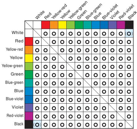
Color vs. Detection Capability E3X-DAC□-S+E32-CC200
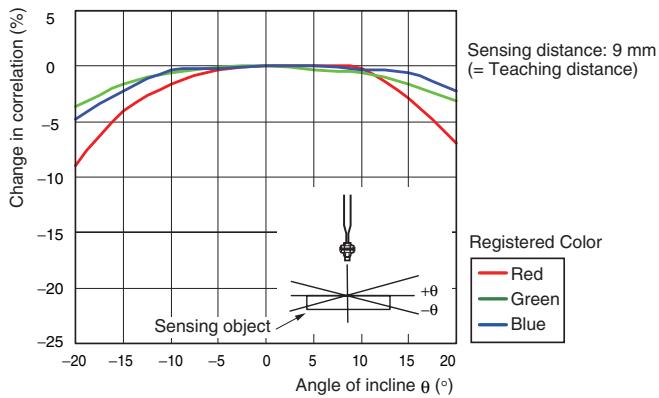
Sensing distance: 9 mm (i.e., the teaching distance)
Detection possible, × Detection not possible.
* Use 2-point teaching to distinguish between white and black.

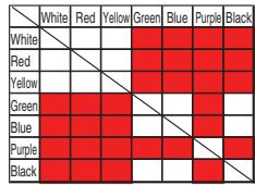
Model with Red Light Source (E3X-DA□-S)
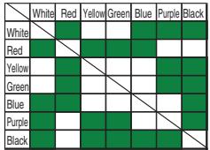
Model with Green Light Source (E3X-DAG□-S)
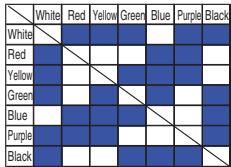
Model with Blue Light Source (E3X-DAB□-S)
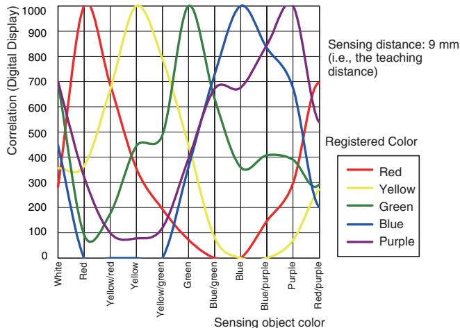
Color Detection Characteristics E3X-DAC□-S+E32-CC200
Correlation vs. Distance E3X-DAC□-S+E32-CC200
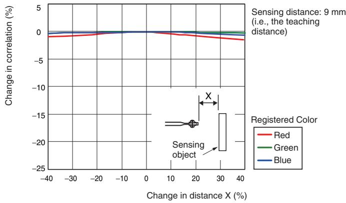
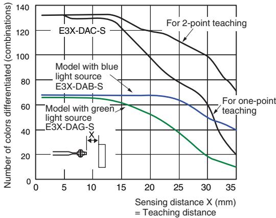
Color Detection Capability vs. Distance
E3X-DA□-S+E32-CC200
E3X-DAB/G□-S+E32-CC200 (Model with single-color light source)
Correlation vs. Angle E3X-DAC□-S+E32-CC200
Output Circuit Diagrams
NPN Output
| Model | Operation mode | Timing charts | Operation selector | Output circuit |
| E3X-DAC11-S | ON for match | Match Mismatch ON (orange) OFF | LIGHT ON (L-ON) | Display Operation indicator (orange) mode indicator (orange) Brown Black Load 12 to 24 VDC |
| E3X-DAC6-S | Match Mismatch ON (orange) OFF | |||
| ON for mis-match | Match Mismatch ON (orange) OFF | DARK ON (D-ON) | ||
| Match Mismatch ON (orange) OFF | ||||
| Match Mismatch ON (orange) OFF | ||||
| Match Mismatch ON (orange) OFF | ||||
| Match Mismatch ON (orange) OFF | ||||
| Match Mismatch ON (orange) OFF | ||||
| Match Mismatch ON (orange) OFF | ||||
| Match Mismatch ON (orange) OFF | ||||
| Match Mismatch (Relay) OFF | ||||
| Load Operate (relay) Reset (Between brown and black leads) | ||||
| E3X-DAC21-S | ON for match | Match Mismatch ON (orange) OFF | LIGHT ON (L-ON) | Display Ch2 operation indicator (orange) Brown Black Load 12 to 24 VDC |
| Match Mismatch ON (orange) OFF | ||||
| Match Mismatch ON (orange) OFF | ||||
| Match Mismatch ON (orange) OFF | ||||
| Match Mismatch ON (orange) OFF | ||||
| Match Mismatch ON (orange) OFF | ||||
| Match Mismatch ON (orange) OFF | ||||
| Match Mismatch ON( relay) Reset (Between brown and black leads) |
PNP Output
| Model | Operation mode | Timing charts | Operation selector | Output circuit |
| E3X-DAC41-S | ON for match | Match Mismatch | LIGHT ON (L-ON) | Display I mode indicator (orange) Brown |
| E3X-DAC8-S | Operation indicator (orange) OFF | |||
| Output transistor ON | ||||
| Load Operate (relay) Reset (Between blue and black leads) | ||||
| ON for mis-match | Match Mismatch | DARK ON (D-ON) | Display Ch2 operation indicator (orange) Brown | |
| Operation indicator (orange) OFF | ||||
| Output transistor ON | ||||
| Load Operate (relay) Reset (Between blue and black leads) | ||||
| E3X-DAC51-S | ON for match | Match Mismatch | LIGHT ON (L-ON) | Display Ch1 operation indicator (orange) Pink Ch1 control output 12 to 24 VDC |
| Operation indicator (orange) OFF | ||||
| Output transistor ON | ||||
| Load Operate (relay) Reset (Between blue and black leads) | ||||
| ON for mis-match | Match Mismatch | DARK ON (D-ON) | Display Ch2 operation indicator (orange) Blue Load | |
| Operation indicator (orange) OFF | ||||
| Output transistor ON | ||||
| Load Operate (relay) Reset (Between blue and black leads) |
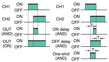
Note:1. Timing Charts for Timer Function Settings (T: Set Time)
2. Control Output (AND, OR, Sync) and Timing Chart for Timer Settings (T: Set Time)
| ON delay | OFF delay | One-shot |
| Match Mismatch L-ON OFF D-ON | Match Mismatch L-ON OFF D-ON | Match Mismatch L-ON OFF D-ON |
Amplifier Units
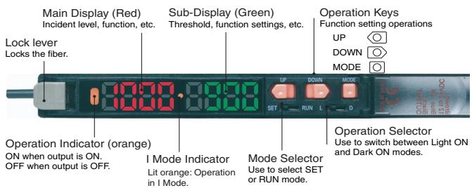
Standard Models
E3X-DAC□-S (□: 11/41/6/8)
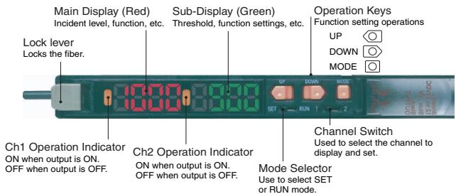
Advanced Models
E3X-DAC□-S(□:21/51)
Safety Precautions

WARNING
This product is not designed or rated for ensuring safety of persons either directly or indirectly.
Do not use it for such purposes.


CAUTION
Do not use the product with voltage in excess of the rated voltage. Excess voltage may result in malfunction or fire.

Never use the product with an AC power supply. Otherwise, explosion may result.

High-temperature environments may result in burn injury.

Precautions for Safe Use
The following precautions must be observed to ensure safe operation of the Sensor.
- Do not use the Sensor in an environment where explosive or flammable gas is present.
- Do not use the Sensor in a location subject to splattering of water, oils, or chemicals.
- Do not attempt to disassemble, repair, or modify the Sensor.
- Do not apply voltages or currents that exceed the rated range to the Sensor.
- Do not use the Sensor in an ambient atmosphere or environment that exceeds the ratings.
- Wire the power supply correctly, including the polarity.
- Connect the load correctly.
- Do not short-circuit the load at both ends.
- Do not use the Sensor if the case is damaged.
- Dispose of the Sensor as industrial waste.
- Do not use the Sensor in locations subject to direct sunlight.
- Burn injury may occur. The Sensor surface temperature rises depending on application conditions, such as the ambient temperature and the power supply voltage. Use caution when operating or performing maintenance on the Sensor.
Precautions for Correct Use
Do not use the product in atmospheres or environments that exceed product ratings.
Amplifier Unit
Designing
Operation after Turning Power ON
The Sensor is ready to detect within 200 ms after the power supply is turned ON. If the Sensor and load are connected to separate power supplies, be sure to turn ON the Sensor first. Time may be required for the incident level to stabilize after the power supply is turned ON.
Operation When Turning Power OFF
Output pulses may occur when the power is turned OFF. Turn OFF the power supply to the load and the load line before turning OFF the power supply to the Sensor.
Mounting
Connecting and Disconnecting Connectors
Mounting Connectors
- Insert the Master or Slave Connector into the Amplifier Unit until it clicks into place.
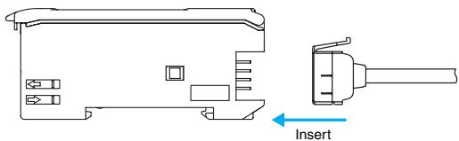
- Attach the protector seals (provided as accessories) to the sides of master and slave connectors that are not connected.
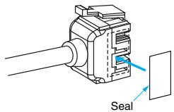
Note: Attach the seals to the sides with grooves.
Removing Connectors
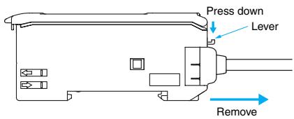
- Slide the slave Amplifier Unit(s) for which the Connector is to be removed away from the rest of the group.
- After the Amplifier Unit(s) has been separated, press down on the lever on the Connector and remove it. (Do not attempt to remove Connectors without separating them from other Amplifier Units first.)
Adding and Removing Amplifier Units
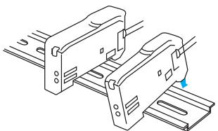
Adding Amplifier Units
- Mount the Amplifier Units one at a time onto the DIN track.
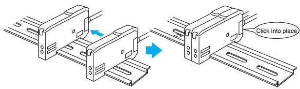
- Slide the Amplifier Units together, line up the clips, and press the Amplifier Units together until they click into place.
Removing Amplifier Units
Slide Amplifier Units away from each other, and remove from the DIN track one at a time. (Do not attempt to remove Amplifier Units from the DIN track without separating them first.)
Note:1. The specifications for ambient temperature will vary according to the number of Amplifier Units used together. For details, refer to Ratings and Specifications.
2. Always turn OFF the power supply before joining or separating Amplifier Units.
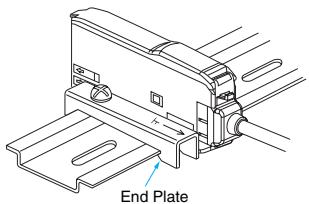
Mounting the End Plate (PFP-M)
An End Plate should be used if there is a possibility of the Amplifier Unit moving, e.g., due to vibration.
Fiber Connection
The E3X Amplifier Unit has a lock button for easy connection of the Fiber Unit. Connect or disconnect the fibers using the following procedures:
1. Connection
Open the protective cover, insert the fibers according to the fiber insertion marks on the side of the Amplifier Unit, and lower the lock lever.
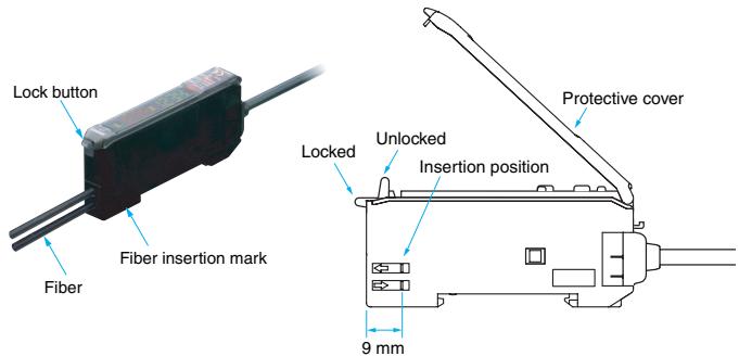
Note: Do not pull on, compress, or otherwise exert excessive force on the fibers after connecting them to the Amplifier Unit. (Do not exert more than 0.3 N·m.)
2. Disconnecting Fibers
Remove the protective cover and raise the lock lever to pull out the fibers.
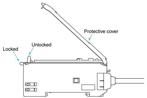
Note:1. To maintain the fiber properties, confirm that the lock is released before removing the fibers.
2. Be sure to lock or unlock the lock button within an ambient temperature range between -10^ and 40^ .
Adjusting
Mutual Interference Protection Function
Light from other sensors can cause the value on the digital display to become somewhat unstable. If this occurs, reduce the threshold to create a greater margin and enable more stable detection.
Shorting the Output
If the output short-circuit function operates because the load connected to the control output is short-circuited, OVER/CUR will flash on the display. Check the connection of the load.
EEPROM Writing Error
If the data is not written to the EEPROM correctly due to a power failure or static-electric noise, initialize the settings with the keys on the Amplifier Unit. ERR/EEP will flash on the display when a writing error has occurred.
Optical Communications
Several Amplifier Units can be slid together and used in groups. Do not, however, slide the Amplifier Units or attempt to remove any of the Amplifier Units during operation.
Others
Protective Cover
Always keep the protective cover in place when using the Amplifier Unit.
Fiber Unit
Design Precautions
Applicable Fiber Units
Refer to the sensing distance tables on pages 8 to 10 for the Fiber Units that can be used and the sensing distances. Retro-reflective, Limited-reflective, Ultra-compact, and Application-specific Fiber Units, which are not listed, cannot be used.
- Installation Precautions
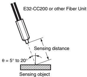
Glossy Sensing Objects
If the sensing object is glossy, detection may not be stable. If the Sensor is inclined by 5^ to 20^ when using a glossy sensing object, as shown below, detection capabilities can be increased and stable detection achieved.
Amplifier Units
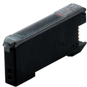
Amplifier Units with Cables
E3X-DAC11-S
E3X-DAC41-S
E3X-DAC21-S
E3X-DAC51-S
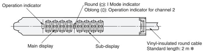

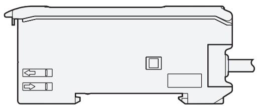
*Cable Specifications
| E3X-DAC11-S -DAC41-S | 4-dia., 3-conductor (Conductor cross section: 0.2 mm², insulator diameter: 1.1 mm) |
| E3X-DAC21-S -DAC51-S | 4-dia., 5-conductor (Conductor cross section: 0.2 mm², insulator diameter, 1.1 mm) |
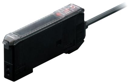
With Mounting Bracket Attached
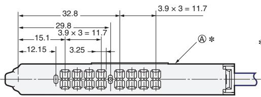
* The Mounting Bracket can also be used on this side.
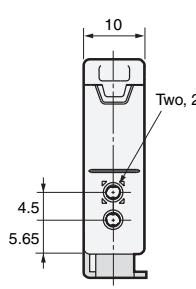
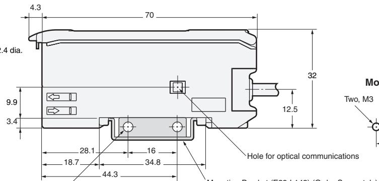
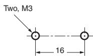
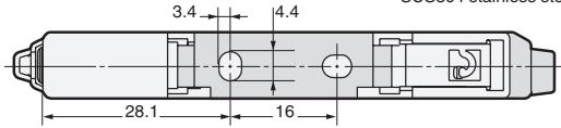
Mounting Holes
Two, 3.2 dia. holes
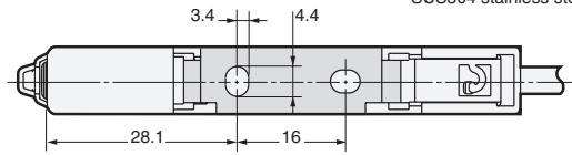
Mounting Bracket (E39-L143) (Order Separately) SUS30 stainless steel
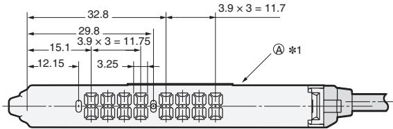
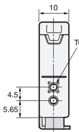
Amplifier Units with Connectors
E3X-DAC6-S
E3X-DAC8-S

With Mounting Bracket Attached
2 Cable Diameters
1 The Mounting Bracket can also be used on this side.
| E3X-CN11 (3 conductor) | 4.0-mm dia. |
| E3X-CN12 (1 conductor) | 2.6 mm dia. |
Two, 2.4
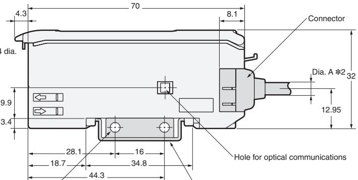
Two, 3.2-dia. holes
Mounting Bracket (E39-L143)
SUS304 stainless steel
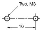
Mounting Holes
Amplifier Unit Connectors
Master Connectors
E3X-CN11
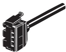
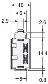
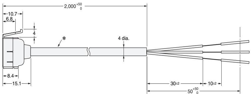
* E3X-CN11: 4-dia. vinyl-insulated round cable with 3 conductors (Conductor cross section: 0.2 mm^2 ,Insulator diameter: 1.1 mm )
Slave Connectors
E3X-CN12
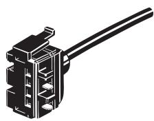
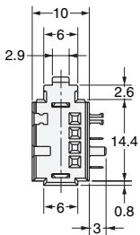
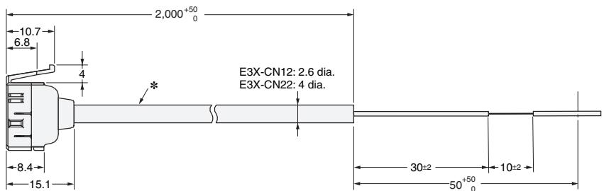
* E3X-CN12: 2.6-dia. vinyl-insulated round cable with 1 conductor (Conductor cross section: 0.2 mm^2 ,Insulator diameter: 1.1 mm )
Refer to the E32 Series Fiber Sensor Best Selection Guide (Cat. No. E353).
Operation Reference
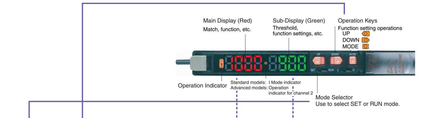
| SET/RUN mode | Operation Keys | Operation | Displays | Remarks | |
| Main Display | Sub-Display | ||||
| Detection/ adjustment RUN (Factory-set to RUN) | UP DOWN | Adjusting thresholds | Incident level | Threshold | → Page 19 Refer to 3. Setting Thresholds Manually in RUN Mode. |
| MODE | Executing user-speci-fied functions (Factory-set to 1-point teaching.) | Used to executes various teaching and zero-reset operations. → Page 19 Refer to 2. Registering Work-piece Colors with Teaching in SET Mode. | |||
| Function settings SET | UP DOWN | Changing teaching and setting details | Setting items | Setting details | → Page 19 Refer to 2. Registering Work-piece Colors with Teaching in SET Mode. |
| MODE | Switching setting items | → Page 20 Refer to 4. Setting Functions in SET Mode. | |||
| SET/RUN mode | Operation Keys | Operation | Display | Remarks | |
| Main Display | Sub-Display | ||||
| RUN (Factory-set to RUN) | UP + MODE | Locking and unlocking keys | LOC | ON | Locks key operation to prevent incorrect operation. → Page 21 Refer to 5. Convenient Functions. |
| SET | UP + DOWN | Initialization and user re-set | INIT | YES? | Returns the system to its initial state. → Page 21 Refer to 5. Convenient Functions. |
1 Setting the Operation Mode
The operation mode is set with the Mode Selector.
| Operation mode | Operation | |
| Match ON | L-ON | L (Factory-set) |
| Mismatch ON | D-ON | D |
- Advanced Models
The operation mode is set in SET mode.
Page 20 Refer to 4. Setting Functions in SET Mode.
- Advanced Models
Set the Channel Selector to the desired channel before making any adjustments or settings. This is true for all adjustments and settings.
2 Registering Workpiece Colors with Teaching in SET Mode
工 *Workpiece colors must always be taught to perform judgment for registered workpiece colors.
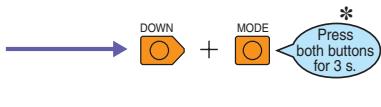
- With the factory settings, 1-point teaching can be executed in RUN mode. (Press the MODE Key for 3 s.)
2-1. One-point Teaching
Along with registering the workpiece colors, the threshold can be set at approximately -10% of the match.
The setting is completed in a simple operation with one press of a button.

- The threshold level can be changed if the teaching level function is used in SET mode.
- If BLACK mode is selected as the judgment mode in SET mode, the threshold will be set to a level of approximately 10% higher than the displayed degree of matching.
2-2. Teaching with and without the Workpiece
Two points, with and without the workpiece, are detected, and the match of the intermediate point is set as the threshold value.
This method is ideal for setting thresholds with margins or performing judgments with low match.
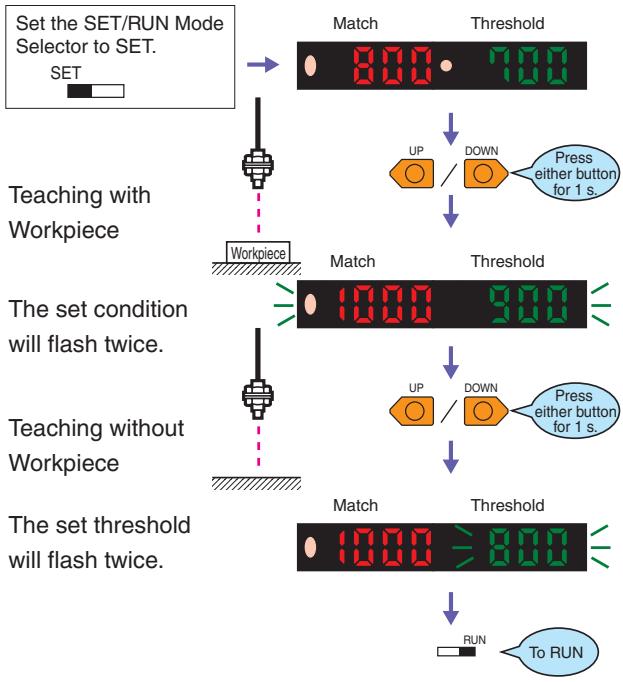
- When teaching is performed, position the workpiece by using the OVER, OK, and LO messages displayed on the sub-display (green) as guides.
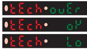
OVER:Move the workpiece away.
OK : Teaching is possible.
LO :Move the workpiece closer.
3 Setting Thresholds Manually in RUN Mode
A threshold can be set manually. A threshold value can also be fine-tuned using manual setting after teaching.
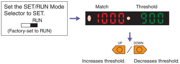
- Even if the display method for the Display Switch Function is changed, the threshold will appear on the sub-display when the key is pressed.
4 Setting Functions in SET Mode
Function Transitions Page 19
Refer to 2. Registering Workpiece Colors with Teaching in SET Mode
Set the SET/RUN Mode Selector to SET.
SET

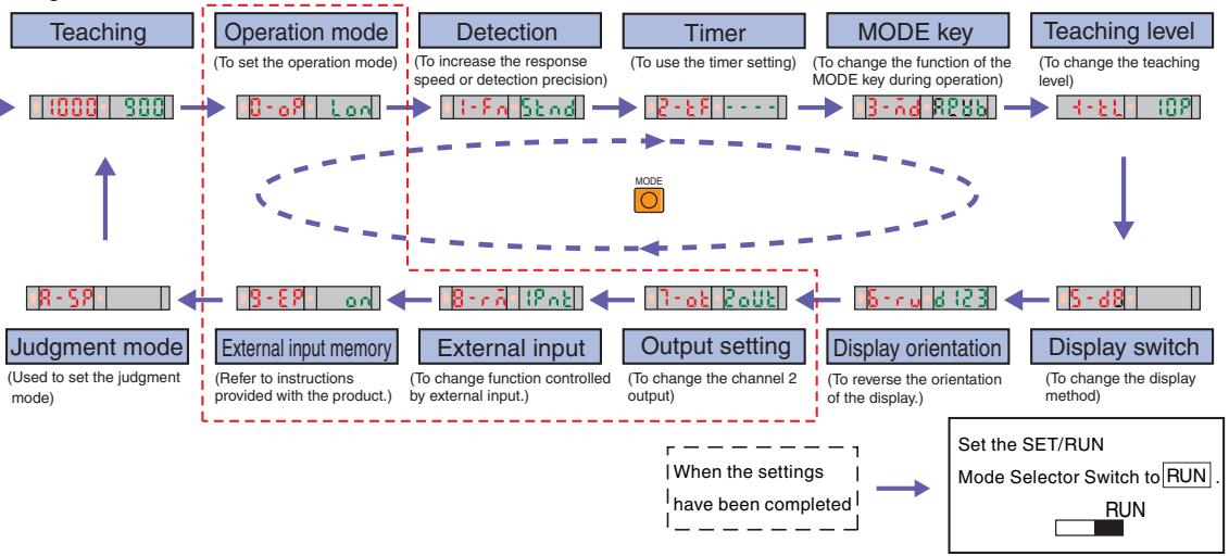
Functions
Use the UP and DOWN Keys to change the settings.
| Function | Settings (display) | Description | |
| Operation mode | Match: ON, Mon, Mismatch: don | → Page 19 Refer to 1. Setting the Operation Mode. | |
| Detection | Super-high-speed: 5K, High-speed: K5, Standard: S and High-resolution: H8, Note: If the detection function is changed, be sure to teach the workpiece color. | Used to increase the response speed or detection precision. Note: Only I Mode (light intensity determination for red, green, or blue) can be used with Super-high-speed mode. | |
| Timer | Enabled: ----, OFF-delay timer: aFFd ON-delay timer: on-d, One-shot timer: 1sht | Used to set control output timers. | |
| Timer time (timer enabled) | 1 to 5000 ms: 1 to 5000 (1 to 20: 1-ms increments, 20 to 200 ms: 5-ms increments, 200 to 1000: 100-ms increments, 1000 to 5000: 1000-ms increments) | Used to change timer times. The timer can be set from 1 ms to 5 s. | |
| MODE key | 1-point teaching: Pnt, Teaching with workpiece: Pnt Zero-shift reset: Qr-Sf → Page 21 Refer to 5-1. Zeroing the Display (Zero Reset). | Used to change the function of the MODE key during operation. | |
| Teaching level | 0 to 99P: 0 to 93 | Used to change the threshold setting level during 1-point teaching. [Example: The threshold level at the default setting (1G) is 300. When the setting is 2G, the threshold level is 800.] | |
| Display switch | (1) Match/threshold: 85G1500 (2) Margin/threshold: P123500 (3) Peak/Bottom refreshed every 2 s: PERM both (4) Peak/Bottom refreshed every time the output is switched: L-Pe D-bt (5) Analog bar display: | | | | | | | | | | | | | | | | | | | | | | | | | | | | | | | | | | | | | | | | | | | | | | | | | | | | | | | | | | | | | | | | | | | | | | | | | | | | | | | | | | | | | | | | | | | | | | | | | | | | | 1. Used to display the degree of matching and the threshold. 2. Used to display the excess gain (i.e., percentage of matching relative to threshold) and the threshold. 3. Used to display the peak and bottom degrees of matching at a fixed interval. 4. Used to display the peak degree of matching when there is a match and the bottom degree of matching when there is no match. 5. Used to show the detection status with a bar display. Red bars will be displayed if the degree of match exceeds the threshold. 6. Used to display the present degree of matching and the peak degree of matching. 7. Used to display the degree of matching and channel number. | |
| Display orientation | Normal display: d 123, Upside down display: E2; P | Used to change the orientation of the display. | |
| Output setting | Each channel: 2a1b, AND: Rnd, OR: ar | Used to change the item output on control output 2. | |
| Timer function | Enabled: ----, OFF-delay timer: aFFd ON-delay timer: on-d, One-shot timer: 1sht | Used to set timers for the AND/OR control output. | |
| Timer time | 1 to 5000 ms: 1 to 5000 (1 to 20: 1-ms increments, 20 to 200 ms: 5-ms increments, 200 to 1000: 100-ms increments, 1000 to 5000: 1000-ms increments) | Used to change timer time. The timer can be set from 1 ms to 5 s. | |
| External input | 1-point teaching: Pnt, Teaching without workpiece: Pnt Zero-shift reset: Qr-St, Light OFF: Loff | Used to change the functions to be remotely controlled with external input. (For the effective pulse width and other information, refer to the instructions provided with the product.) | |
| External input memory | Write: an, Do not write: aFF | Used to set whether to write the control results to memory. (Refer to the instructions provided with the product.) | |
| Judgment mode | C/I automatic judgment: Ruta, C mode:c, I mode: I BLACK mode: bL' | Used to set the judgment mode (detection method). BLACK mode: The total light intensity for red, green, and blue is used for the judgment. | |
The displays shown in the function transitions are for the default settings.
Items shown in the function transitions may increase depending on detailed settings.
The items enclosed by dotted red lines are for advanced models only.
5 Convenient Functions
5-1. Zeroing the Display (Zero Reset)
The incident light level on the main display can be set to 0. This is useful when the reference display is to be reset to zero because the match display and the threshold are shifted at the same time.
* Change the function to 0RST (zero reset) with the MODE key. The default setting is 1PNT.
Page 20 Refer to 4. Setting Functions in SET Mode.
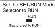


To return to original value for incident light level:
- Press the DOWN key right after pressing the MODE key.
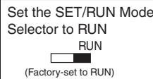
5-2. Locking the Keys (Key Lock)
All key operations can be disabled.
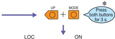
"ON" will flash twice and key operations will be disabled.

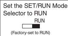
To release the lock:
Set the SET/RUN Mode Selector to RUN

(Factory-set to RUN)

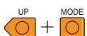
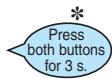

"OFF" will flash twice and key operations will be enabled.
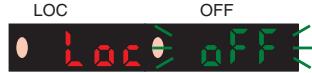
If a key is pressed while key operations are locked, "LOC" will flash
twice on the display to indicate that key operations have been disabled.

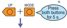
- Press the UP key right after pressing the MODE key.
5-3. Saving a Set State (Saving User Settings)



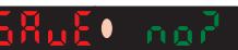

SAVE
YES?



SAVE

User settings saved.
Operation canceled.
- Be sure to register (i.e., teach) the workpiece colors if the detection functions have been changed.
5-4. Initializing Settings (Initialization and User Reset)
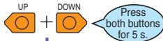
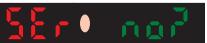
All settings will be initialized and returned to the factory settings or to a saved state.
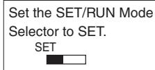
Set the SET/RUN Mode Selector to SET.



RST

RST
USER





USER
NO?

USER
YES?


Settings initialized.
Operation canceled.
The section enclosed by dotted lines applies to user-saved settings.

INIT
NO?
INIT
YES?




Operation canceled.
Initialized.
READ AND UNDERSTAND THIS DOCUMENT
Please read and understand this document before using the products. Please consult your OMRON representative if you have any questions or comments.
WARRANTY
OMRON's exclusive warranty is that the products are free from defects in materials and workmanship for a period of one year (or other period if specified) from date of sale by OMRON.
OMRON MAKES NO WARRANTY OR REPRESENTATION, EXPRESS OR IMPLIED, REGARDING NON-INFRINGEMENT, MERCHANTABILITY, OR FITNESS FOR PARTICULAR PURPOSE OF THE PRODUCTS. ANY BUYER OR USER ACKNOWLEDGES THAT THE BUYER OR USER ALONE HAS DETERMINED THAT THE PRODUCTS WILL SUITABLY MEET THE REQUIREMENTS OF THEIR INTENDED USE. OMRON DISCLAIMS ALL OTHER WARRANTYES, EXPRESS OR IMPLIED.
LIMITATIONS OF LIABILITY
OMRON SHALL NOT BE RESPONSIBLE FOR SPECIAL, INDIRECT, OR CONSEQUENTIAL DAMAGES, LOSS OF PROFITS OR COMMERCIAL LOSS IN ANY WAY CONNECTED WITH THE PRODUCTS, WHETHER SUCH CLAIM IS BASED ON CONTRACT, WARRANTY, NEGLIGENCE, OR STRICT LIABILITY.
In no event shall responsibility of OMRON for any act exceed the individual price of the product on which liability is asserted.
IN NO EVENT SHALL OMRON BE RESPONSIBLE FOR WARRANTY, REPAIR, OR OTHER CLAIMS REGARDING THE PRODUCTS UNLESS OMRON'S ANALYSIS CONFIRMS THAT THE PRODUCTS WERE PROPERLY HANDLED, STORED, INSTALLED, AND MAINTAINED AND NOT SUBJECT TO CONTAMINATION, ABUSE, MISUSE, OR INAPPROPRIATE MODIFICATION OR REPAIR.
SUITABILITY FOR USE
THE PRODUCTS CONTAINED IN THIS DOCUMENT ARE NOT SAFETY RATED. THEY ARE NOT DESIGNED OR RATED FOR ENSURING SAFETY OF PERSONS, AND SHOULD NOT BE RELIED UPON AS A SAFETY COMPONENT OR PROTECTIVE DEVICE FOR SUCH PURPOSES. Please refer to separate catalogs for OMRON's safety rated products.
OMRON shall not be responsible for conformity with any standards, codes, or regulations that apply to the combination of products in the customer's application or use of the product.
At the customer's request, OMRON will provide applicable third party certification documents identifying ratings and limitations of use that apply to the products. This information by itself is not sufficient for a complete determination of the suitability of the products in combination with the end product, machine, system, or other application or use.
The following are some examples of applications for which particular attention must be given. This is not intended to be an exhaustive list of all possible uses of the products, nor is it intended to imply that the uses listed may be suitable for the products:
- Outdoor use, uses involving potential chemical contamination or electrical interference, or conditions or uses not described in this document.
- Nuclear energy control systems, combustion systems, railroad systems, aviation systems, medical equipment, amusement machines, vehicles, safety equipment, and installations subject to separate industry or government regulations.
- Systems, machines, and equipment that could present a risk to life or property.
Please know and observe all prohibitions of use applicable to the products.
NEVER USE THE PRODUCTS FOR AN APPLICATION INVOLVING SERIOUS RISK TO LIFE OR PROPERTY WITHOUT ENSURING THAT THE SYSTEM AS A WHOLE HAS BEEN DESIGNED TO ADDRESS THE RISKS, AND THAT THE OMRON PRODUCT IS PROPERLY RATED AND INSTALLED FOR THE INTENDED USE WITHIN THE OVERALL EQUIPMENT OR SYSTEM.
PERFORMANCE DATA
Performance data given in this document is provided as a guide for the user in determining suitability and does not constitute a warranty. It may represent the result of OMRON's test conditions, and the users must correlate it to actual application requirements. Actual performance is subject to the OMRON Warranty and Limitations of Liability.
CHANGE IN SPECIFICATIONS
Product specifications and accessories may be changed at any time based on improvements and other reasons.
It is our practice to change model numbers when published ratings or features are changed, or when significant construction changes are made. However, some specifications of the product may be changed without any notice. When in doubt, special model numbers may be assigned to fix or establish key specifications for your application on your request. Please consult with your OMRON representative at any time to confirm actual specifications of purchased products.
DIMENSIONS AND WEIGHTS
Dimensions and weights are nominal and are not to be used for manufacturing purposes, even when tolerances are shown.
ERRORS AND OMISSIONS
The information in this document has been carefully checked and is believed to be accurate; however, no responsibility is assumed for clerical, typographical, or proofreading errors, or omissions.
PROGRAMMABLEPRODUCTS
OMRON shall not be responsible for the user's programming of a programmable product, or any consequence thereof.
COPYRIGHT AND COPY PERMISSION
This document shall not be copied for sales or promotions without permission.
This document is protected by copyright and is intended solely for use in conjunction with the product. Please notify us before copying or reproducing this document in any manner, for any other purpose. If copying or transmitting this document to another, please copy or transmit it in its entirety.

OMRON Corporation
Industrial Automation Company
Sensing Devices Division H.Q.
Industrial Sensors Division
Shiokoji Horikawa, Shimogyo-ku,
Kyoto, 600-8530 Japan
Tel: (81)75-344-7022/Fax: (81)75-344-7107
Regional Headquarters
OMRON EUROPE B.V.
Sensor Business Unit
Carl-Benz-Str. 4, D-71154 Nufringen,
Germany
Tel: (49) 7032-811-0/Fax: (49) 7032-811-199
OMRON ELECTRONICS LLC
One Commerce Drive Schaumburg,
IL 60173-5302 U.S.A.
Tel: (1) 847-843-7900/Fax: (1) 847-843-7787
OMRON ASIA PACIFIC PTE. LTD.
No. 438A Alexandra Road # 05-05/08 (Lobby 2),
Alexandra Technopark, Singapore 119967
Tel: (65) 6835-3011/Fax: (65) 6835-2711
OMRON (CHINA) CO., LTD.
Room 2211, Bank of China Tower,
200 Yin Cheng Zhong Road,
PuDong New Area, Shanghai, 200120, China
Tel: (86) 21-5037-2222/Fax: (86) 21-5037-2200
Authorized Distributor:
© OMRON Corporation 2007 All Rights Reserved.
In the interest of product improvement,
specifications are subject to change without notice.
- The Fiber Sensor That Sees in Color
- Easy and Reliable ... Featuring a Color-sensing Engine
- Thinnest in the Industry
- A Slim, 10-mm-wide Amplifier Unit
- Easy and Reliable ... Ease of Use and Smart Functions
- First in Its Class
- Easy and Reliable ... Simplified Wiring Connector Reduces Work Steps
- Wide Range of Fiber Heads Available
- Easy and Reliable Applications (Examples)
- Ordering Information
- Combining Amplifier Units and Connectors
- Output Circuit Diagrams
- Amplifier Units
- Standard Models
- Advanced Models
- E3X-DAC□-S(□:21/51)
- Safety Precautions
- WARNING
- CAUTION
- Precautions for Safe Use
- Precautions for Correct Use
- Amplifier Unit
- Designing
- Operation after Turning Power ON
- Operation When Turning Power OFF
- Mounting
- Connecting and Disconnecting Connectors
- Mounting Connectors
- Removing Connectors
- Adding and Removing Amplifier Units
- Adding Amplifier Units
- Removing Amplifier Units
- Mounting the End Plate (PFP-M)
- Fiber Connection
- Connection
- Disconnecting Fibers
- Adjusting
- Mutual Interference Protection Function
- Shorting the Output
- EEPROM Writing Error
- Optical Communications
- Others
- Protective Cover
- Fiber Unit
- Design Precautions
- Applicable Fiber Units
- - Installation Precautions
- Glossy Sensing Objects
- Amplifier Unit Connectors
- Operation Reference
- Setting the Operation Mode
- Registering Workpiece Colors with Teaching in SET Mode
- 2-1. One-point Teaching
- 2-2. Teaching with and without the Workpiece
- Setting Thresholds Manually in RUN Mode
- Setting Functions in SET Mode
- Function Transitions → Page 19
- Functions
- Use the UP and DOWN Keys to change the settings.
- Convenient Functions
- 5-1. Zeroing the Display (Zero Reset)
- 5-2. Locking the Keys (Key Lock)
- 5-4. Initializing Settings (Initialization and User Reset)
- READ AND UNDERSTAND THIS DOCUMENT
- WARRANTY
- LIMITATIONS OF LIABILITY
- SUITABILITY FOR USE
- PERFORMANCE DATA
- CHANGE IN SPECIFICATIONS
- DIMENSIONS AND WEIGHTS
- ERRORS AND OMISSIONS
- PROGRAMMABLEPRODUCTS
- COPYRIGHT AND COPY PERMISSION
- OMRON Corporation
- OMRON ELECTRONICS LLC
- OMRON ASIA PACIFIC PTE. LTD.
- OMRON (CHINA) CO., LTD.
- Authorized Distributor:
Brand : OMRON
Model : E3X-DAC-S
Category : Fiber Optic Sensor