
E3X - Optical sensor OMRON - Free user manual and instructions
Find the device manual for free E3X OMRON in PDF.


| Product Type | Optical detection sensor |
| Brand | OMRON |
| Model | E3X |
| Dimensions (L x W x H) | 50 x 30 x 20 mm |
| Weight | 50 g |
| Power supply | 12 to 24 VDC |
| Power consumption | 40 mA max. |
| Output type | NPN or PNP (depending on model) |
| Detection range | Up to 10 m (depending on sensor head) |
| Wavelength | Infrared (880 nm) |
| Main functions | Optical detection, sensitivity adjustment, light/dark mode, timer |
| Maintenance and cleaning | Clean the lens with a soft, dry cloth. Do not use solvents. |
| Safety | Respect the rated voltages and currents. Avoid shocks and humidity. |
| Spare parts and repairability | Connection cables, mounting brackets, optional sensor heads. Repair by a professional. |
| General information | Operating temperature: -25 to 55 °C. Protection rating: IP67. |
Frequently Asked Questions - E3X OMRON
User questions about E3X OMRON
0 question about this device. Answer the ones you know or ask your own.
Ask a new question about this device
Download the instructions for your Optical sensor in PDF format for free! Find your manual E3X - OMRON and take your electronic device back in hand. On this page are published all the documents necessary for the use of your device. E3X by OMRON.
USER MANUAL E3X OMRON
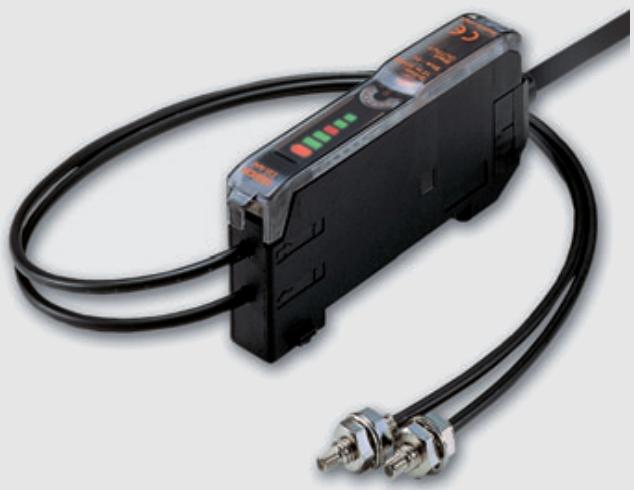
- wide portfolio range of fiber sensing heads
- application oriented design for long operational lifetime
- high precision in design and manufacturing for high application accuracy
- fiber and amplifier designs for easy installation and set up
Features

Long operational lifetime
Ensuring that the sensors do not fail during production and require only minimal service attention enhances productivity and reduces maintenance costs.
- Models with enhanced protection and tested resistance against harsh environments
-
Tested resistance against aggressive chemicals, extreme temperatures, low pressure (vacuum), mechanical abuse
-
Preventing fiber breakage
-
Housing construction preventing protruding cables (e.g. square shape, side view models)
- High flex fibers with 1mm bending radius for close wall mounting
- Robot fibers tested with more than one million bending cycles
-
Protective metal or plastic tubes
-
Operational stability
-
LED power control against aging effects
- Auto-threshold control for enhanced compensation of power decrease, e.g. through dirt on lenses
Easy to set up and adjust
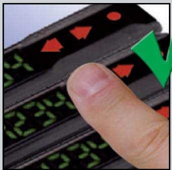
With minimal time required for mounting the fibers the productivity can be enhanced for machine builders and the easy setting of the amplifiers simplifies production changes for machine users.
- Easy-teach amplifiers or manual adjusters
- Easy manual adjustment by potentiometer
-
One-button auto teach for in-process dynamic teaching, or two-point object teaching
-
Wide range of easy-to-mount fibers
One-screw-mount fibers with hexagonal back - Square shapes for simple surface mounting
- Side view for simple alignment
- Application-optimised housings (e.g. fork shape for label and foil detection, tube for liquid level detection, etc.)
High accuracy in smallest size
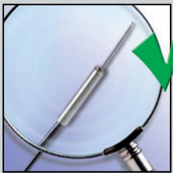
OMRON's precise manufacturing processes with inspection system supported alignment of the fibers and lenses achieve minimal tolerance variations in all standard models and allow the detection of the smallest objects and height differences of less than 100 m .
- High beam axis accuracy for side view models through precise fiber bending or angle mirror surface treatment
- High spot evaluation precision on coaxial models through equal fiber distribution
- Accurate distance setting through precise lens and beam alignment
Standard cylindrical fiber sensor heads
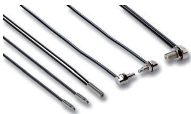
The standard cylindrical fiber optic sensing heads provide reliable object detection, easy installation and long sensor lifetime for all general applications.
- High-flex fibers and 90^ cable exit for cable breakage prevention
- Models with hexagonal back for simplified one-nut mounting
- Sizes M3 to M6
Ordering information
| Sensor type | Size | Sensing distance (in mm) *1 | Order code | ||
| Standard | High-flex | Standard | High-flex | ||
| M4 | 760 | 530 | E32-TC200 2M | E32-ET11R 2M | |
| M3 | 220 | 130 | E32-TC200E 2M | E32-ET21R 2M | |
| M4 | - | 530 | - | E32-T11N 2M | |
| M6 | 250 *2 | - | E32-R21 | - | |
| M6 | 300 | 170 | E32-DC200 2M | E32-ED11R 2M | |
| M4 | 80 | 30 | E32-D211 2M | E32-D211R 2M | |
| M3 | 80 | 30 | E32-DC200E 2M | E32-ED21R 2M | |
| M6 | - | 170 | - | E32-D11N 2M | |
| dia 6 mm | 110 | 45 | E32-D14L 2M | E32-D14LR 2M | |
*1 Sensing distance measured with E3X-DA-S family in standard mode. In high resolution mode the sensing distance is approx. 30% higher.
Measured with E39-R3
Specifications
| Item | Standard | High Flex | ||||||||
| E32- _C200 | E32-D14L | E32- _C200E | E32-D211 | E32-R21 | E32-E_R | E32-D14LR | E32-D211R | E32- _11N | ||
| Permissible bending radius | R25 | R10 | R1 | |||||||
| Cut to length | Yes | |||||||||
| Material | Head | Brass-nickel plated | Stainless steel | Brass-nickel plated | Stainless steel | Plastic (ABS) | Brass-nickel plated | Stainless steel | Brass-nickel plated | |
| Fiber | PMMA | |||||||||
| Sheath | Polyethylene coating | PVC coating | ||||||||
| Degree of protection | IEC 60529 IP67 | |||||||||
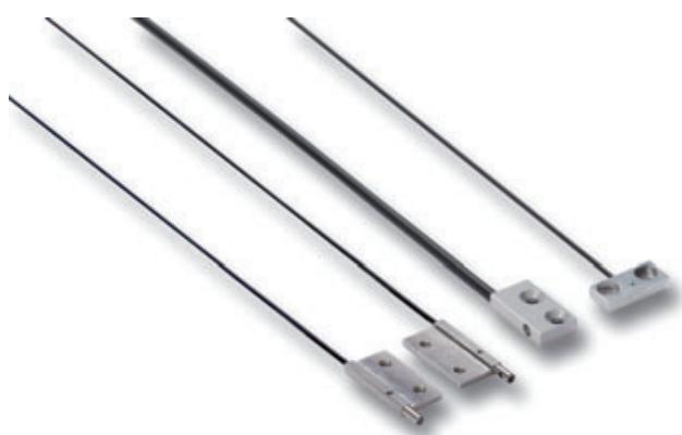
Square shape fiber sensor heads
The fiber heads in square shaped housing provide fast and easy installation on flat surfaces.
- Models with sensing direction in X, Y or Z axis
- 3 or 4mm thick housings for minimal height requirement
- Standard or high-flex fibers
Ordering information
| Sensor type | Size (in mm) | Sensing distance (in mm) *1 | Order code | ||
| Standard | High-flex | Standard | High-flex | ||
| → | 15x18x3/15x10x4 | 760 | 560 | E32-T15X 2M | E32-ETS10R 2M |
| → | 15x18x3 | 460 | 210 | E32-T15Y 2M | E32-T15YR 2M |
| ← | 15x18x3/15x9x4 | 460 | 480 | E32-T15Z 2M | E32-ETS14R 2M |
| 15x10x3 | 300 | 170 | E32-D15X 2M | E32-D15XR 2M | |
| ← | 15x10x3 | 100 | 40 | E32-D15Y 2M | E32-D15YR 2M |
| 15x10x3/13x6x2.3 | 100 | 60 | E32-D15Z 2M | E32-EDS24R 2M | |
| → | 24.5x10x3 | 890 | - | E32-A03-1 2M | - |
| 20.5x2x2 | 340 | - | E32-A04-1 2M | - | |
*1 Sensing distance measured with E3X-DA-S family in standard mode. In high resolution mode the sensing distance is approx. 30% higher.
Specifications
| Item | Standard | High flex | |||
| E32-15 | E32-A | E32-E | E32-15_R | ||
| Permissible bending radius | R25 | R10 | R1 | ||
| Cut to length | Yes | ||||
| Material | Head | Aluminium | Brass-nickel plated | Aluminium | |
| Fiber | PMMA | ||||
| Sheath | Polyethylene coating | PVC coating | |||
| Degree of protection | IEC 60529 IP67 | IEC 60529 IP50 | IEC 60529 IP67 | ||
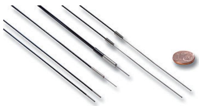
Miniature fiber sensor heads
The miniature fiber heads provide high accuracy in smallest spaces and reliable detection of minute objects.
- Sizes from dia 500 m to 3 mm
- Side view models with precision axis alignment for highest accuracy
- Bendable sleeves for precision positioning
Ordering information
| Sensor type | Size | Sensing distance (in mm)*1 | Order code | ||
| Standard | High-flex | Standard | High-flex | ||
| dia 3 mm | 750 | 530 | E32-T12 2M | E32-T12R 2M | |
| dia 2 mm | 220 | 130 | E32-T22 2M | E32-T22R 2M | |
| dia 1.5 mm | 220 | 130 | E32-T222 2M | E32-T222R 2M | |
| dia 1 mm | - | 130 | - | E32-T223R 2M | |
| dia 3 mm | 460 | 210 | E32-T14L 2M | E32-T14LR 2M | |
| dia 2 mm | 340 | - | E32-A04 2M | - | |
| dia 1 mm | 130 | 50 | E32-T24 | E32-T24R 2M | |
| *2 | dia 1.2 mm | 750 | 530 | E32-TC200B | E32-TC200BR |
| dia 0.9 mm | 220 | 130 | E32-TC200F | E32-TC200FR | |
| dia 3 mm | 80 | 30 | E32-D22 2M | E32-D22R 2M | |
| dia 2 mm | 75 | 40 | E32-D32 2M | E32-D32R 2M | |
| dia 1.5 mm | - | 30 | - | E32-D22B 2M | |
| dia 2 mm | 30 | 15 | E32-D24 | E32-D24R 2M | |
| *2 | dia 2.5 mm | 300 | 170 | E32-DC200B 2M *3 | E32-DC200BR *3 |
| dia 1.2 mm | 80 | 30 | E32-DC200F | E32-DC200FR | |
| dia 0.8 mm | - | 16 | - | E32-D33 2M | |
| dia 0.5 mm | - | 3 | - | E32-D331 2M | |
*1 Sensing distance measured with E3X-DA-S family in standard mode. In high resolution mode the sensing distance is approx. 30% higher.
Models with 40 mm sleeve instead of 90 mm sleeve are available by adding '4' to the order code at the end, e.g. E32-TC200B4
3 Sleeve cannot be bent
Specifications
| Item | Standard | High-flex | ||||||||||
| E32-DC200B | E32-T14L | E32-D32 | E32-D22 | E32-D24 | E32-D24 | E32-D32R | E32-D33 | E32-D22B | E32-DC200BR | E32-D22R | ||
| E32-T12 | E32-T222 | E32-DC200F | E32-DC200F | E32-D33 | E32-D331 | E32-T12R | E32-T222R | |||||
| E32-TC200B | E32-TC200F | E32-T22 | E32-T24 | E32-TC200BR | E32-TC200FR | |||||||
| Permissible bending radius | R25 | R10 | R4 | R1 | ||||||||
| Cut to length | Yes | |||||||||||
| Material | Head | Brass-nickel plated | Stainless steel | Brass-nickel plated | Stainless steel | Brass-nickel plated | Stainless steel | |||||
| Fiber | PMMA | |||||||||||
| Sheath | Polyethylene coating | PVC and polyethylene | Polyethylene coating | PVC and polyethylene | PVC coating | Polyethylene coating | ||||||
| Degree of protection | IEC 60529 IP67 | IEC 60529 IP50 | IEC 60529 IP67 | |||||||||
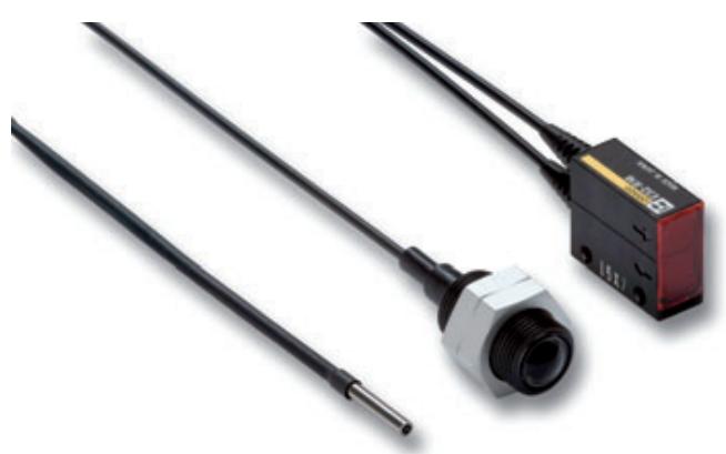
Longer distance fiber sensor heads
With built-in focal lenses the longer distance fiber heads provide enhanced operational stability in dusty environments or long distance applications
Sensing distance up to 20m
Built-in focal lens
- Sizes from dia 2mm to M14
Ordering information
| Sensor type | Size | Sensing distance (in mm)*1 | Order code |
| M14 | 20000 | E32-T17L | |
| 25,2x10.5x8 mm | 3400 | E32-T14 | |
| M4 | 1330 | E32-T11L 2M | |
| M3 | 680 | E32-TC200A 2M | |
| dia 3 mm | 1330 | E32-T12L 2M | |
| dia 2 mm | 440 | E32-T22L 2M | |
| 21.5x27x10 mm | 1500 *2 | E32-R16 2M | |
| 22x17.5x9 mm | 700 | E32-D16 2M | |
| M6 | 400 | E32-D11L 2M | |
| M4 | 130 | E32-D21L 2M | |
| dia 3 mm | 230 | E32-D12 2M |
Sensing distance measured with E3X-DA-S family in standard mode. In high resolution mode the sensing distance is approx. 30% higher.
*2 Measured with E39-R1
Specifications
| Item | Through-beam | Retroreflective | Diffuse reflective | |||||||
| E32-T17L/E32-T14 | E32-T11L/E32-T12L | E32-TC200A | E32-T22L | E32-R16 | E32-D16 | E32-D11L | E32-D21L | E32-D12 | ||
| Permissible bending radius | R25 | R10 | R25 | R4 | R25 | R10 | R25 | |||
| Cut to length | Yes | |||||||||
| Material | Head | ABS | Brass-nickel plated | Stainless steel | ABS | Aluminium | Brass-nickel plated | Stainless steel | ||
| Fiber | PMMA | |||||||||
| Sheath | Polyethylene coating | PVC coating | Polyethylene coating | |||||||
| Degree of protection | IEC 60529 IP67 | IEC 60529 IP40 | IEC 60529 IP67 | |||||||
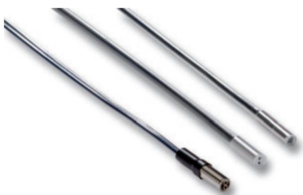
Chemical resistant fiber sensor heads
The chemical resistant fibers provide long sensor lifetime in areas with frequent cleaning, usage of chemicals and higher temperatures.
- fluoroplastic cover for highest chemical resistance
temperature resistance up to 200^
Ordering information
| Sensor type | Size | Sensing distance (in mm)*1 | Key feature | Order code |
| →→→ | M4 | 680 | Fluororesin coating | E32-T11U 2M |
| →→→ | dia 5 mm | 3,000 | Fluororesin cover | E32-T12F |
| →→→ | dia 5 mm | 1,400 | Fluororesin cover | E32-T14F 2M |
| →→→ | M6 | 170 | Fluororesin coating | E32-D11U 2M |
| →→→ | dia 6 mm | 95 | Fluororesin cover | E32-D12F |
| ←→→ | dia 6 mm | 40 | Fluororesin cover | E32-D14F 2M |
| →→→ | dia 6 mm | 700 | Fluororesin cover Heat resistant to 200°C | E32-T81F-S 2M |
| →→→ | dia 5 mm | 3,000 | Fluororesin cover Heat resistant to 150°C | E32-T51F 2M |
^*1 Sensing distance measured with E3X-DA-S family in standard mode. In high resolution mode the sensing distance is approx. 30% higher.
Specifications
| Item | Fluororesin coating | Full fluororesin cover | Full fluororesin cover and heat resistance | |||
| E32-T11U | E32-D11U | E32- _12F/E32- _14F | E32-T51F | E32-T81F-S | ||
| Permissible bending radius (in mm) | 1 | 4 | 40 | 10 | ||
| Cut to length | yes | no | ||||
| Material | Head | Brass-nickel plated | Fluororesin | |||
| Fiber | PMMA | Glass | ||||
| Sheath | Fluororesin coating | Fluororesin cover | ||||
| Degree of protection | IEC60529 IP67 | |||||
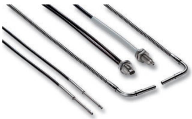
Heat resistant fiber sensor heads
The wide range of heat resistant fibers provides long sensor lifetime with highest protection in demanding environments
heat resistant up to 400^
- sizes from dia 2 mm to M6
- models for long distances or high detection accuracy
Ordering information
| Sensor type | Size | Sensing distance (in mm)*1 | Key feature | Order code | |
| For E3X-DA-S teachable amplifier | for E3X-NA amplifier with potentiometer adjustment | ||||
| M4 | 450 | -40°C to 150°C | E32-ET51 2M | ||
| M4 | 280 | -40°C to 200°C | E32-T81R-S 2M | ||
| M4 | 450 | -60°C to 350°C | E32-T61-S 2M | ||
| dia 2 mm | 230 | -40°C to 150°C | E32-T54 2M | ||
| dia 3 mm | 1300 | -40°C to 200°C | E32-T84S-S 2M | ||
| M6 | 230 | -40°C to 150°C | E32-ED51 2M | ||
| M6 | 280 | -40°C to 200°C | E32-D81R-S 2M | E32-D81R 2M | |
| M6 | 150 | -60°C to 350°C | E32-D61-S 2M | E32-D61 1M | |
| M4 | 60 | -40°C to 400°C | E32-D73-S 2M | E32-D73 | |
| 23x20x9 mm | 35 | -40°C to 150°C | E32-A09H 2M | ||
| 30x24x9 mm | 25 | -40°C to 300°C | E32-A09H2 2M | ||
*1 Sensing distance measured with E3X-DA-S family in standard mode. In high resolution mode the sensing distance is approx. 30% higher.
Specifications
| Item | -40°C to 150°C | -40°C to 200°C | -40°C to 300°C | -60°C to 350°C | -40°C to 400°C | ||||
| E32-E_51 | E32-T54 | E32-A09H | E32- _81_ | E32-T84_ | E32-A09H2 | E32- _61_ | E32-D73_ | ||
| Permissible bending radius (in mm) | R35 | R10 | R25 | ||||||
| Cut to length | Yes | No | |||||||
| Material | Head | Brass-nickel plated | Stainless steel | Aluminium | Stainless steel | ||||
| Fiber | Fluoro resin | PMMA | Glass | ||||||
| Sheath | Fluoro resin | Stainless steel spiral coating | Stainless steel tube | Stainless steel spiral coating | Stainless steel tube | ||||
| Degree of protection | IEC 60529 IP67 | ||||||||
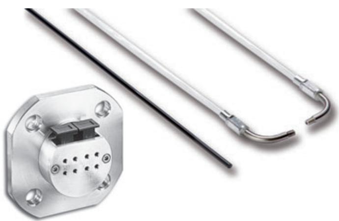
Vacuum resistant fiber sensor heads
For applications in cleanest and hot environments the vacuum resistant fibers and connecting flanges provide long operational lifetime and vacuum integrity.
- Leakage rate of 1 × 10^-6 ~Pa^ m^3 / s max
- Heat resistance up to 200^
- Detergent resistant fluororesin or stainless steel fiber sheath
Ordering information
Sensor
| Sensor type | Size | Sensing distance (in mm) *1 | Temperature range | Order code |
| M4 | 200 | -40°C to 120°C | E32-T51V 1M | |
| dia 3 | 130 | -40°C to 120°C | E32-T54V 1M | |
| dia 3 | 480 | -60°C to 200°C | E32-T84SV 1M |
^*1 Sensing distance measured with E3X-DA-S family in standard mode. In high resolution mode the sensing distance is approx. 30% higher.
Flange
| Type | Size | Order code |
| 4 channel flange | 80x80x49 mm | E32-VF4 |
| 1 channel flange | 96 x dia30 mm max. | E32-VF1 |
| Flange-to-amplifier connection fiber | 2 m length | E32-T10V 2M |
Specifications
| Item | Fiber sensor heads | Flange-to-amplifier fiber | |||
| E32-T51V | E32-T54V | E32-T84SV | E32-T10V | ||
| Permissible bending radius | R30 | R25 | |||
| Cut to length | No | Yes | |||
| Material | Head | Aluminium | Stainless steel | - | |
| Fiber | Glass | PMMA | |||
| Sheath | Fluoresin coating | Stainless steel spiral coating | Polyethylene coating | ||
| Degree of protection | - | ||||
| Item | Flange | ||
| E32-VF1 | E32-VF4 | ||
| Leakage rate | 1x10⁻¹⁰ Pa*m³/s max | ||
| Ambient temperature | -25°C to 55°C | ||
| Material | Flange | Aluminium and stainless steel | Aluminium |
| Seal | Fluorocarbon rubber (viton) | ||
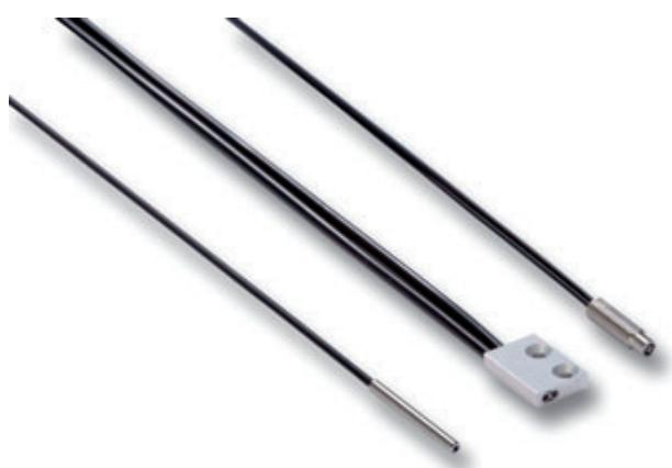
Robot application fiber sensor heads
For applications on frequently or fast moving parts, the robot fibers reduce the risk of fiber breakage with a guaranteed operational life of more than 1 million bending cycles
Free moving multicore fibers for >1 mio bending cycles
- Square shapes for easy surface installation
Cylindrical sizes from dia 1.5 mm to M6
Ordering information
| Sensor type | Size | Sensing distance (in mm) *1 | Order code |
| M4 | 680 | E32-T11 2M | |
| M3 | 200 | E32-T21 2M | |
| dia 3 mm | 680 | E32-T12B | |
| dia 2 mm | 200 | E32-T221B | |
| dia 1.5 mm | 200 | E32-T22B | |
| 15x18x3 mm | 680 | E32-T15XB 2M | |
| M6 | 170 | E32-D11 2M | |
| M4 | 70 | E32-D21B 2M | |
| M3 | 30 | E32-D21 2M | |
| dia 1.5 mm | 30 | E32-D22B 2M | |
| 15x10x3 mm | 170 | E32-D15XB 2M |
^*1 Sensing distance measured with E3X-DA-S family in standard mode. In high resolution mode the sensing distance is approx. 30% higher.
Specifications
| Item | Square | Cylindrical | ||||
| E32-D15XB | E32-T21 | E32-D11 | E32-D21 | E32-D21B | ||
| E32-T15XB | E32-T11 | E32-T12B | E32-D22B | |||
| E32-T22B | E32-T221B | |||||
| Permissible bending radius | R4 | |||||
| Cut to length | Yes | |||||
| Material | Head | Aluminium | Brass-nickel plated | Stainless steel | ||
| Fiber | PMMA | |||||
| Sheath | PVC coating | Polyethylene coating | PVC coating | |||
| Degree of protection | IEC 60529 IP67 | |||||
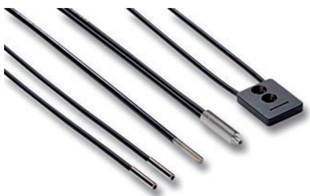
Precision detection fiber sensor heads
Highest precision in design and manufacturing of the fibers and focal lenses ensure highest beam and spot accuracy allowing the detection of smallest objects and height differences of less than 100 m .
Coaxial fibers with focal lenses for spot diameters of 100 m
- Through-beam models with highly focused beam and precise optical axis alignment
- Limited reflective models for height difference detection of less than 100 m
Ordering information
| Sensor type | Preferred usage | Size | Key feature | Sensing distance (in mm)*1 | Order code |
| Precise thin object detection / accurate positioning | dia 3 mm | - High precision optical axis adjustment | 1900 | E32-T22S | |
| dia 3 mm | - Very focused beam | 890 | E32-A03 2M | ||
| dia 2 mm | 340 | E32-A04 2M | |||
| Very small object detection | M6 | - | 300 | E32-CC200 2M *2 | |
| M3 | Spot dia 0.5 mm | 20 | E32-EC31 2M | ||
| M3 | Spot dia 0.2 mm | 17 | E32-EC41 1M + E39-F3B | ||
| M3 | Spot dia 0.1 mm | 7 | E32-EC41 1M + E39-F3A-5 | ||
| dia 3 mm | - | 150 | E32-D32L | ||
| dia 2 mm | - | 75 | E32-D32 2M *2 | ||
| M6 | - 90° cable exit - Hexagonal back | 170 | E32-C11N 2M | ||
| M3 | 25 | E32-C31N 2M | |||
| M3 | Small spot | 8-25 m adjustable | E32-EC31 2M + E39-EF51 | ||
| dia 2 mm | Spot dia 0.5 to 1 mm | 6-15 mm adjustable | E32-D32 2M + E39-F3A | ||
| dia 2 mm | Spot dia 0.1 to 0.6 mm | 6-15 mm adjustable | E32-C42 1M | ||
| Precision height difference detection / flat surface detection | 23x20x9 mm | - | 35 | E32-A09 2M | |
| 16x18x4 mm | - | 7.2 | E32-L25L *2 | ||
| 20x20x5 mm | - | 3.3 | E32-L25 | ||
| 18x20x4 mm | Precise spot e.g. for detection of a flat / reflective surface | 4 | E32-L24L *2 | ||
| 34x25x8 | Vaery precise spot (detection accuracy 100 μm) | 2.4 | E32-EL24-1 2M | ||
| Object detection in front of background | 22.5x17.5x3.8 mm | Wide beam e.g. for object detection on a flat surface | 15 | E32-L16 2M |
^*1 Sensing distance measured with E3X-DA-S family in standard mode. In high resolution mode the sensing distance is approx. 30% higher.
^2 A high flex cable version is available. Add 'R' to the order code, e.g. E32-CC200R
Specifications
| Item | Through-beam | Diffuse reflective (coaxial) | Limited reflective | |||||||||
| E32-T22S | E32-A03 | E32-A04 | E32-C11N E32-C31N | E32-CC200 | E32-C42 E32-D32/-D32L E32-EC31/-EC41 | E32-EL24-1 | E32-L24L E32-L25L | E32-L25 | E32-L16 | E32-A09 | ||
| Permissible bending radius | R10 | R1 | R10 | R4 | R25 | R10 | R25 | |||||
| Cut to length | Yes | |||||||||||
| Material | Head | Brass-nickel plated | Stainless steel | Brass-nickel plated | Stainless steel | Brass-nickel plated and aluminium | Polycarbonate | ABS | Aluminium | |||
| Fiber | PMMA | |||||||||||
| Sheath | PVC coating | Polyethylene coating | PVC coating | PVC, polyethylene and polyolefin coating | Polyethylene coating | |||||||
| Degree of protection | IEC 60529 IP67 | IP50 | IEC 60529 IP67 | IEC 60529 IP50 | IEC 60529 IP40 | |||||||
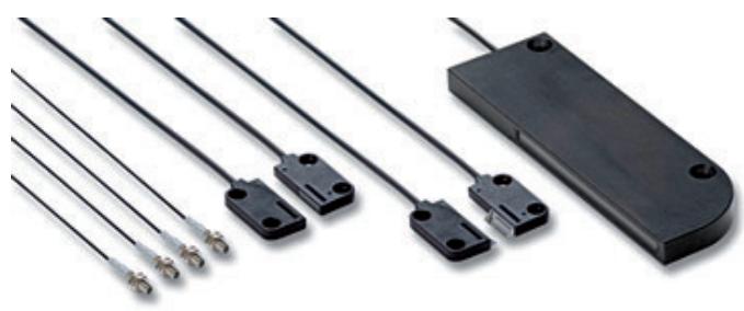
Area monitoring fiber sensor heads
The area monitoring fibers allow the detection of objects passing anywhere through the detection range and can be used for height comparisons of different objects.
- Area monitoring up to 70mm height
- Multi-beam sensor with 4 separate heads for flexible detection points
- Standard or high flex fibers
Ordering information
| Sensor type | Area hight (in mm) | Sensing distance (in mm)*1 | Order code | ||
| Standard | High-flex | Standard | High-flex | ||
| *2 | 10 | 2800 | - | E32-T16 | - |
| 11 | 1100 | 840 | E32-T16P | E32-T16PR 2M | |
| 30 | 1800 | 1300 | E32-T16W 2M | E32-T16WR 2M | |
| 50 | - | 1800 | - | E32-ET16WR-2 2M | |
| 70 | - | 2000 | - | E32-ET16WR-1 2M | |
| 11 | 1000 | 750 | E32-T16J 2M | E32-T16JR 2M | |
| 4* seperate M3 heads | 610 | - | E32-M21 | - | |
| 11 | - | 150 | - | E32-D36P1 2M | |
*1 Sensing distance measured with E3X-DA-S family in standard mode. In high resolution mode the sensing distance is approx. 30% higher.
Sensing area aligned to top of housing.
Specifications
| Item | Standard | High-flex | |||||
| E32-T16 | E32-M21 | E32-T16J E32-T16P E32-T16W | E32-D36P1 | E32-ET16WR-1 E32-ET16WR-2 | E32-T16JR E32-T16PR E32-T16WR | ||
| Permissible bending radius | R25 | R10 | R4 | R1 | |||
| Cut to length | Yes | ||||||
| Material | Head | ABS | Stainless steel | ABS | Brass-nickel plated | Aluminium | ABS |
| Fiber | PMMA | ||||||
| Sheath | Polyethylene coating | PVC coating | Polyethylene coating | PVC coating | |||
| Degree of protection | IEC 60529 IP67 | IEC 60529 IP50 | IEC 60529 IP54 | IEC 60529 IP50 | |||
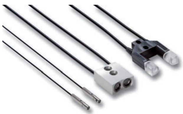
Special application fiber sensor heads
For a wide range of special applications, the task optimised fiber heads provide best fitting sensing performance and adaption to environmental requirements.
- Detection of special objects (liquids, transparent foils, etc.)
- Fiber heads ideal for colour mark detection
- Fiber heads optimised for special tasks (wafer mapping, hot reflective surface detection, etc.)
Ordering information
| Senor Type | Size | Sensing distance (in mm) *1 | Comment | Order code | |
| Fork shape | 36x24x8 mm | 10 | - | E32-G14 | |
| Wafer mapping | dia 3 | 1900 | - | E32-T22S | |
| dia 3 | 1300 | - | E32-T24S | ||
| dia 3 | 890 | - | E32-A03 2M | ||
| dia 2 | 340 | - | E32-A04 2M | ||
| Liquid level sensor | dia 6 | liquid contact | Liquid level contact | E32-D82F1 4M | |
| 15x23.5x5 mm | tube contact | Liquid level detection through transparent tube or container | E32-D36T 2M | ||
| Label detection | 20x20x5 mm | 7.2 | - | E32-L25L | |
| 18x20x4 mm | 4 | - | E32-L24L | ||
| 34x25x8 mm | 2.4 | Very precise spot (detection accuracy 100 μm) | E32-EL24-1 2M | ||
| Colour detection *2 | M6 | 300 | Recommended for standard colour and colour mark detection | E32-CC200 2M | |
| 23x20x9 mm | 35 | Recommended for higher precision colour and colour mark detection | E32-A09 2M | ||
| M3 | 20 | Recommended for very precise colour mark detection | E32-EC31 2M | ||
| Transparent foil detection | M4 | depends on application | With amplifier E3X-DA_S and powertuning functionality | E32-ET11R + E39-F1 | |
| 36x24x8 mm | 10 | - Fork shape for simplified mounting - Only with amplifier E3X-DAC_S | E32-G14 | ||
| Detection of hot reflective surfaces | 36x18x5.5 mm | 18 | - Heat resistant up to 300°C - Limited reflective for accurate detection of shiny surfaces - Wide beam for tilt resistance tolerance of object surface | E32-L66 2M | |
*1 Sensing distance measured with E3X-DA-S family in standard mode. In high resolution mode the sensing distance is approx. 30% higher.
*2 With amplifier E3X-DAC-S
Specifications
| Item | E32-D82F1 | E32-G14 | E32-A09 | E32-CC200 | E32-EC31 | E32-L66 | E32-EL24-1 | E32-T22S E32-T24S | E32-L24L E32-L25L | E32-A04 | E32-D36T | E32-A03 | E32-ET11R | |
| Permissible bending radius | R40 | R25 | R10 | R4 | R1 | |||||||||
| Cut to length | Yes | No | Yes | |||||||||||
| Material | Head | PFA | ABS | Aluminium | Brass-nickel plated | Stainless steel | Brass-nickel plated and aluminium | Brass-nickel plated | Stainless steel | ABS | Brass-nickel plated | |||
| Fiber | PMMA | Glass | PMMA | |||||||||||
| Sheath | Polyethylene coating | PVC, polyethylene and polylefin coating | Stainless steel spiral coating | Polyethylene coating | PVC coating | Polyethylene coating | PVC coating | Polyethylene coating | PVC coating | |||||
| Degree of protection | IEC 60529 IP67 | IEC 60529 IP40 | IEC 60529 IP67 | IEC 60529 IP40 | IEC 60529 IP67 | IEC 60529 IP50 | IEC 60529 IP67 | IEC 60529 IP50 | IEC 60529 IP67 | |||||
Accessories
| Shape | Type | Comment | Order code |
| Focal lens | - Extends sensing distance by more than 500% - For M4 Through beam fibers E32-TC200, E32-ET11R, E32-T11 (fits M2.6 thread) - 2 pcs per set | E39-F1 | |
| Focal lens (side view) | - For M4 through beam fibers E32-TC200, E32-ET11R, E32-T11, E32-T61-S, E32-T81R-S (fits M2.6 thread) - Temperature range -40°C to +200°C - 2 pcs per set | E39-F2 | |
| Focal lens (variable) | - For precision detection with E32-D32 | E39-F3A | |
| Focal lens | - For precision detection with E32-EC41 | E39-F3A-5 | |
| Focal lens | - For precision detection with E32-EC41 | E39-F3B | |
| Focal lens (side view, variable) | - For precision detection with E32-EC31 | E39-EF51 | |
| Focal lens (heat resistant) | - Extends sensing distance by more than 500% - For M4 through beam fibers E32-ET51, E32-T61, E32-T61-S, E32-T81R, E32-T81R-S (fits M4 thread) - Temperature range -60°C to +350°C - 2 pcs per set | E39-EF1-37 | |
| Focal lens (vacuum resistant, heat resistant) | - Fits E32-T51V and E32-T54V (fits M2.6 thread) - 2 units per set - Heat resistant up to 120°C | E39-F1V | |
| Fiber cutter | - Included in applicable fiber | E39-F4 | |
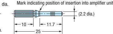
| Thin fiber attachment | - Amplifier adapter for thin fibers - Included in applicable fiber (2 sets) | E39-F9 | |
| Sleeve bender | - For E32-TC200B(4) - For E32-TC200F(4) - For E32-DC200F(4) | E39-F11 | |
| Single fiber extension connector | - Fiber extension connector for 2.2 mm dia standard fibers - One unit | E39-F10 | |
| Dual fiber extension connector | - For fibers with dia 2.2 - For fiber with dia 1.0 - For fibers with dia between 1.0 and 2.2 | E39-F13 | |
| E39-F14 | |||
| E39-F15 | |||
| Protective spiral tube *1 | - For M3 diffuse type sensors - Length 1 m | E39-F32A | |
| - For M3 through beam type sensors - Length 1 m | E39-F32B | ||
| - For M4 through beam type sensors - Length 1 m | E39-F32C | ||
| - For M6 diffuse type sensors - Length 1 m | E39-F32D | ||
| Fiber on roll *2 | - Dia 2.2 mm - Standard monocore, 10 mm bending radius - -40°C to 80°C | E32-E01 100M | |
| - Dia 1.1 mm - Standard monocore, 4 mm bending radius - -40°C to 80°C | E32-E02 100M | ||
| - Dia 2.2 mm - High flex multicore, 1 mm bending radius - -40°C to 80°C | E32-E01R 100M | ||
| - Dia 1.1 mm - High flex multicore, 1 mm bending radius - -40°C to 80°C | E32-E02R 100M | ||
| - Dia 2.2 mm - High temperature monocore, 20 mm bending radius - -60°C to 150°C | E32-E05 100M | ||
| Reflectors | - Size 60 x 40.3 x 7.5 | E39-R1S | |
| - Size 42 x 22.5 x 11 | E39-R3 |
1 Protective spiral tubes with 0.5 m length are available. Add '5' to order code...e.g. E39-F32A5
2 Fiber length 100 m on a roll - cuttable

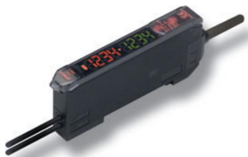
Digital fiber amplifier with one button teaching
E3X-DA-SE-S allows easy one button setting and provides the best value performance ratio for standard applications.
- Auto-teaching during machine operation
- Digital double display for incident level and threshold
- Object or 2-point teaching within a few seconds
Ordering information
| Item | Order code | |
| NPN output | PNP output | |
| Pre-wired | E3X-DA11SE-S 2M | E3X-DA41SE-S 2M |
| Connector version*1 | E3X-DA6SE-S | E3X-DA8SE-S |
*1 Order connector separately.
Specifications
| Item | E3X-DA_SE-S | |
| Light source (wave length) | Red LED (650 nm) | |
| Power supply voltage | 12 to 24 VDC ±10%, ripple (p-p): 10% max. | |
| Protective circuits | Power supply reverse polarity protection, output short-circuit protection, mutual interference prevention | |
| Response time | Operation or reset: 1 ms | |
| Sensitivity setting | Teaching and digital up/down keys | |
| Functions | Auto power control | High-speed control method for emission current |
| Mutual interference prevention | Optical communications sync, possible for up to 10 Units | |
| Digital displays | Incident level + threshold | |
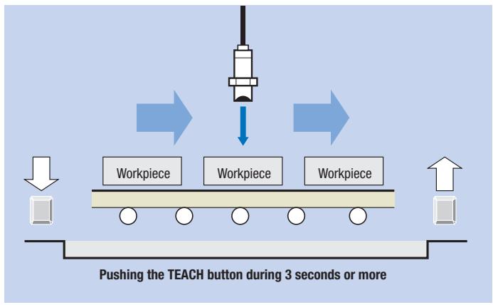
1-button auto-teaching
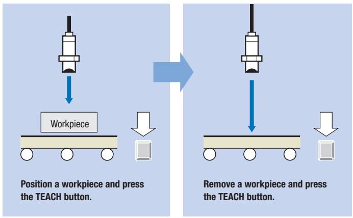
2-point teaching
Fiber amplifier connectors
| Shape | Type | Comment | Order code |
| Fiber amplifier connector | 2 m PVC cable | E3X-CN21 | |
| 30 cm PVC cable with M12 plug connector (4 pin) | E3X-CN21-M1J 0.3M | ||
| 30 cm PVC cable with M8 plug connector (4 pin) | E3X-CN21-M3J-2 0.3M |
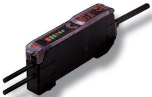
Digital fiber amplifier for basic applications
The E3X-NA/E3X-SD is the ideal amplifier for basic fiber applications providing quick & easy adjustment.
- Easy adjustment with potentiometer (E3X-NA) or up/down keys (E3X-SD)
- Mutual interference prevention
- Enhanced water resistance types
Ordering information
Pre-wired
| Item | Order code (for pre-wired types with 2 m cable lenght) | |||
| Manual adjuster | Up/down keys | |||
| NPN output | PNP output | NPN output | PNP output | |
| Standard | E3X-NA11 2M | E3X-NA41 2M | E3X-SD11 2M | E3X-SD41 2M |
| Enhanced water resistance | E3X-NA11V 2M | E3X-NA41V 2M | - | - |
Connector version
| Item | Order code | |||
| NPN output | PNP output | Up/down keys | ||
| NPN output | PNP output | |||
| Standard*1 | E3X-NA6 | E3X-NA8 | E3X-SD6 | E3X-SD8 |
| Enhanced water resistance *2 (M8 connector) | E3X-NA14V | E3X-NA44V | - | - |
1 Order connector separately.
^2 for M8 connector cables refer to accessory datasheet E26E
Specifications
| Item | Manual adjuster | Up/down keys | ||
| Standard | Enhanced water resistance | Standard | ||
| Output | NPN output | E3X-NA11, E3X-NA6 | E3X-NA11V, E3X-NA14V | E3X-SD6/E3X-SD11 |
| PNP output | E3X-NA41, E3X-NA8 | E3X-NA41V, E3X-NA44V | E3X-SD8/E3X-SD41 | |
| Light source (wave length) | Red LED (680 nm) | Red LED (620 nm) | ||
| Power supply voltage | 12 to 24 VDC ±10%, ripple (p-p): 10% max. | |||
| Protective circuit | Reverse polarity protection, output short-circuit protection, mutual interference prevention | |||
| Response time | Operation or reset: 200 μs max. | |||
| Sensitivity setting | 8-turn endless adjuster (potentiometer) | Digital up/down keys | ||
| Functions | OFF-delay timer: 40 ms (fixed) | |||
| Degree of protection | IEC 60529 IP50 (with protective cover attached) | IEC 60529 IP66 (with protective cover attached) | IEC 60529 IP50 (with protective cover attached) | |
Fiber amplifier connectors
| Shape | Type | Comment | Order code |
| Fiber amplifier connector | 2 m PVC cable | E3X-CN21 | |
| E3X-CN21-M1J 0.3M | |||
| 30 cm PVC cable with M12 plug connector (4 pin) | |||
| 30 cm PVC cable with M8 plug connector (4 pin) | E3X-CN21-M3J-2 0.3M |
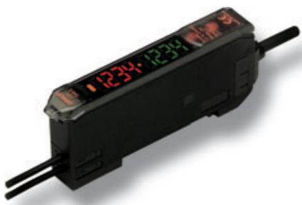
High functionality digital fiber amplifier
High functionality digital fiber amplifier with two large displays for excellent visibility even from a distance.
- Advanced timing, LED power and signal processing functions
- High resolution for long sensing distances and accurate settings
- Auto Power Control for long-term stability
Ordering information
Pre-wired
| Item | Order code (for pre-wired types with 2 m cable length) | ||
| NPN output | PNP output | ||
| Standard models | Red light | E3X-DA11-S 2M | E3X-DA41-S 2M |
| Infrared light | E3X-DAH11-S 2M | E3X-DAH41-S 2M | |
| Twin-output models | E3X-DA11TW-S 2M | E3X-DA41TW-S 2M | |
| External-input models | E3X-DA11RM-S 2M | E3X-DA41RM-S 2M | |
Connector version
| Item | Order code | ||
| NPN output | PNP output | ||
| Standard models *1 | Red light | E3X-DA6-S | E3X-DA8-S |
| Infrared light | E3X-DAH6-S | E3X-DAH8-S | |
| Twin-output models *1 | E3X-DA6TW-S | E3X-DA8TW-S | |
| External-input models *1 | E3X-DA6RM-S | E3X-DA8RM-S | |
*1 Order connector separately
Specifications
Amplifier units with cables
| Item | Standard models | Twin-output models | External-input models | |||
| NPN output | E3X-DA11-S, E3X-DA6-S | E3X-DAH11-S, E3X-DAH6-S | E3X-DA11TW-S, E3X-DA6TW-S | |||
| PNP output | E3X-DA41-S, E3X-DA8-S | E3X-DAH41-S, E3X-DAH8-S | E3X-DA41TW-S, E3X-DA8TW-S | |||
| Light source (wave length) | Red LED (650 nm) | Infrared LED | Red LED (650 nm) | |||
| Power supply voltage | 12 to 24 VDC ±10%, ripple (p-p) 10% max. | |||||
| Protective circuits | Power supply reverse polarity protection, output short circuit protection, mutual interference prevention | |||||
| Response time | Super-high-speed mode | NPN | 48 μs for operation and 50 μs for reset | 80 μs for operation and reset | 48 μs for operation and 50 μs for reset | |
| PNP | 53 μs for operation and 55 μs for reset | 53 μs for operation and 55 μs for reset | ||||
| Standard mode | 1 ms for operation and reset respectively | |||||
| High-resolution mode | 4 ms for operation and reset respectively | |||||
| Sensitivity setting | Teaching and digital up/down keys | |||||
| Functions | Power tuning | Light emission power and reception gain, digital control method | ||||
| Timer function | Select from OFF-delay, ON-delay, or one-shot timer.1 ms to 5 s (1 to 20 ms set in 1-ms increments, 20 to 200 ms set in 10-ms increments,200 ms to 1 s set in 100-ms increments, and 1 to 5 s set in 1 s-increments) | |||||
| I/O settings | - | Output setting(Select from channel 2 output,area output, or self-diagnosis.) | External input setting (Select from teaching, power tuning, zero reset,light OFF, or counter reset.) | |||
| Digital displays | Incident level + threshold or user specific | |||||
Fiber amplifier connectors
| Shape | Type | Comment | Order code |
| Fiber amplifier connector | 2 m PVC cable | E3X-CN21 | |
| 30 cm PVC cable with M12 plug connector (4 pin) | E3X-CN21-M1J 0.3M | ||
| 30 cm PVC cable with M8 plug connector (4 pin) | E3X-CN21-M3J-2 0.3M |
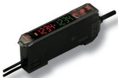
Digital fiber amplifier with active threshold control for dust and dirt compensation
The active threshold E3X-DA-AT-S digital fiber amplifier compensates for light power reduction caused by dirt and ensures stable operation.
Active threshold control for high stability
Alarm output for maintenance warning
Area detection function for quality inspection or sensing range control
Ordering information
| Item | Functions | Order code | |
| NPN output | PNP output | ||
| Pre-wired version | ATC (active threshold control) | E3X-DA11AT-S | E3X-DA41AT-S |
| Connector version*1 | ATC error alarm output | E3X-DA6AT-S | E3X-DA8AT-S |
*1 Order connector separately.
Specifications
| Item | NPN output | E3X-DA11AT-S | E3X-DA6AT-S |
| PNP output | E3X-DA41AT-S | E3X-DA8AT-S | |
| Light source (wave length) | Red LED (650 nm) | ||
| Power supply voltage | 12 to 24 VDC ±10%, ripple (p-p): 10% max. | ||
| Protective circuits | Power supply reverse polarity protection, output short circuit protection, mutual interference prevention | ||
| Response time | Super-high-speed mode | Operation or reset: 80 μs | |
| High-speed mode | Operation or reset: 250 μs | ||
| Standard mode | Operation or reset: 1 ms | ||
| High-resolution mode | Operation or reset: 4 ms | ||
| Sensitivity setting | Teaching and digital up/down keys | ||
| Functions | ATC | Active threshold control (used for output 1) | |
| I/O settings | Used for output 1: ATC error alarm output | ||
| Startup operation | The operation when power is turned ON can be selected: no operation, power tuning or power tuning + ATC | ||
| Digital display | Incident level + threshold or user specific | ||
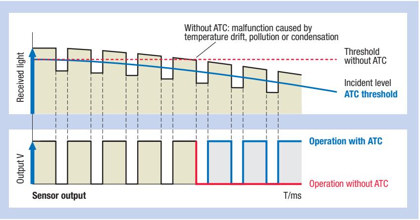
Timing diagram of signal changes with and without ATC
Fiber amplifier connectors
| Shape | Type | Comment | Order code |
| Fiber amplifier connector | 2 m PVC cable | E3X-CN21 | |
| 30 cm PVC cable with M12 plug connector (4 pin) | E3X-CN21-M1J 0.3M | ||
| 30 cm PVC cable with M8 plug connector (4 pin) | E3X-CN21-M3J-2 0.3M |
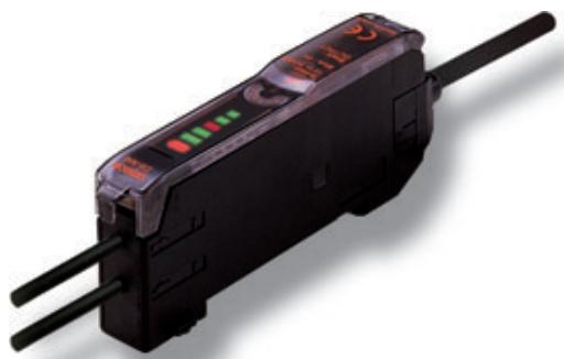
Fast response digital amplifier with potentiometer
The E3X-NA_F provides a very fast response time and is the ideal amplifier for high speed detection applications.
- Short turn on time of only 20~ s
- Easy adjustment with potentiometer
Ordering information
Pre-wired
| Item | Order code | |
| NPN output | PNP output | |
| High-speed detection models | E3X-NA11F | E3X-NA41F |
Specifications
| Item | NPN output | E3X-NA11F |
| PNP output | E3X-NA41F | |
| Light source (wave length) | Red LED (680 nm) | |
| Power supply voltage | 12 to 24 VDC ±10%, ripple (p-p): 10% max. | |
| Protective circuit | Reverse polarity protection, output short-circuit protection, mutual interference prevention | |
| Response time | Operation: 20 μs max. Reset: 30 μs max. | |
| Sensitivity adjustment | 8-turn endless adjuster (potentiometer) | |
| Functions | OFF-delay timer: 40 ms (fixed) | |
| Degree of protection | IEC 60529 IP50 (with protective cover attached) | |
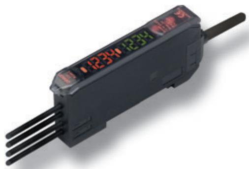
2-in-1 Digital fiber amplifier
E3X-MDA incorporates 2 digital fiber amplifiers in one slimline housing. For applications requiring the detection of two objects simultaneously the E3X-MDA provides an easy to use operation saving space and set-up time.
- Two digital amplifiers in one slimline housing
- Twin output models - on/off or area (between two threshold values)
- Signal comparison functions (AND, OR, etc.)
Ordering information
| Item | Functions | Order code | |
| NPN output | PNP output | ||
| Pre-wired | AND/OR output | E3X-MDA11 | E3X-MDA41 |
| Connector version*1 | AND/OR output | E3X-MDA6 | E3X-MDA8 |
*1 Order connector separately.
Specifications
| Item | E3X-MDA | |
| Light source (wave length) | Red LED (650 nm) | |
| Power supply voltage | 12 to 24 VDC ±10%, ripple (p-p) 10% max. | |
| Protective circuits | Power supply reverse polarity protection, output short-circuit protection, mutual interference prevention | |
| Response time | Super-high-speed mode | 130 μs for operation and reset respectively |
| Standard mode | 1 ms for operation and reset respectively | |
| High-resolution mode | 4 ms for operation and reset respectively | |
| Sensitivity setting | Teaching and digital up/down keys | |
| Functions | Power tuning | Light emission power and reception gain, digital control method |
| Timer function | Select from OFF-delay, ON-delay, or one-shot timer. 1 ms to 5 s (1 to 20 ms set in 1-ms increments, 20 to 200 ms set in 10-ms increments, 200 ms to 1 s set in 100-ms increments, and 1 to 5 s set in 1 s-increments) | |
| I/O settings | Output setting (select from channel 2 output, AND, OR, leading edge sync, falling edge sync, or differential output) | |
| Digital displays | Select from the following: Incident level for channel 1 + incident level for channel 2, Incident level + threshold, incident level percentage + threshold, incident light peak level + no incident light bottom level, minimum incident light peak level + maximum no incident light bottom level, long bar display, incident level + peak hold, incident level + channel | |
Fiber amplifier connectors
| Shape | Type | Comment | Order code |
| Fiber amplifier connector | 2 m PVC cable | E3X-CN21 | |
| 30 cm PVC cable with M12 plug connector (4 pin) | E3X-CN21-M1J 0.3M | ||
| 30 cm PVC cable with M8 plug connector (4 pin) | E3X-CN21-M3J-2 0.3M |
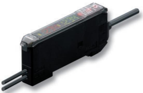
E3X-DAC-S colour (RGB) digital fiber amplifier
The E3X-DAS-C detects the colour of a workpiece and enables it to be compared with a stored RGB ratio to identify coloured marks or workpieces. Moreover, it does this independent of the light intensity and minor sensing distance variations.
- White LED for colour independence
- Fast response time of min. 60~ s
- Timer function for variable ON or OFF delay up to 5 s
Remote teaching or easy one-button teaching
Ordering information
Pre-wired
| Item | Functions | Order code (for pre-wired types with 2 m cable lenght) | |
| NPN output | PNP output | ||
| Standard models | Timer, response speed change | E3X-DAC11-S | E3X-DAC41-S |
| Advanced models | Standard models + simultaneous determination (2 colours) AND/OR output, remote setting | E3X-DAC21-S | E3X-DAC51-S |
Connector versions
| Item | Functions | Order code | |
| NPN output | PNP output | ||
| Standard models *1 | Timer, response speed change | E3X-DAC6-S | E3X-DAC8-S |
*1 Order connector separately
Specifications
| Item | Standard models | Advanced models | |
| E3X-DAC1, E3X-DAC4 E3X-DAC6, E3X-DAC8 | E3X-DAC2, E3X-DAC5 | ||
| Light source (wave length) | White LED (420 to 700 nm) | ||
| Sensing method | C Mode: RGB ratio determination (or I Mode: Light intensity determination for red, green, or blue) | ||
| Number of registered colours | 1 2 (simultaneous determination) | ||
| Power supply voltage | 12 to 24 VDC ±10%, ripple (p-p) 10% max. | ||
| Protective circuits | Power supply reverse polarity protection, output short circuit protection, output reverse polarity protection, mutual interference prevention | ||
| Response time | Super-high-speed mode | Operation or reset: 60 μs | Operation or reset: 120 μs |
| High-speed mode | Operation or reset: 300 μs | Operation or reset: 600 μs | |
| Standard mode | Operation or reset: 1 ms | Operation or reset: 2 ms | |
| High-resolution mode | Operation or reset: 4 ms | Operation or reset: 8 ms | |
| Sensitivity setting (colour registration, allowable range) | Teaching (one-point teaching or teaching with/without workpiece) or manual adjustment | ||
| Functions | Operating mode | ON for match (ON for same colour as registered colour) or ON for mismatch (ON for different colour from registered colour) | |
| Timer function | Timer type: OFF delay, ON delay, or one-short Timer time: 1 ms to 5 s (variable) | ||
| Control outputs | - | Output for each channel, AND output, and OR output | |
| Remote control | - | One-point teaching, teaching with/without workpiece, zero reset, and light emission OFF | |
| Degree of protection | IEC60529 IP50 (with protective cover attached) | ||
Fiber amplifier connectors
| Shape | Type | Comment | Order code |
| Fiber amplifier connector | 2 m PVC cable | E3X-CN21 | |
| 30 cm PVC cable with M12 plug connector (4 pin) | E3X-CN21-M1J 0.3M | ||
| 30 cm PVC cable with M8 plug connector (4 pin) | E3X-CN21-M3J-2 0.3M |
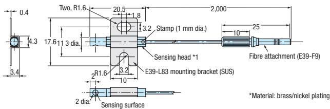
E32-A03
E32-A03-1
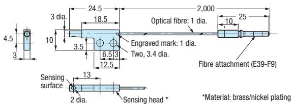
E32-A04
E32-A04-1
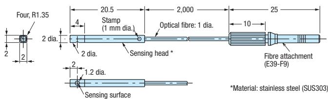
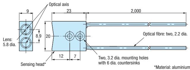
E32-A09, E32-A09H
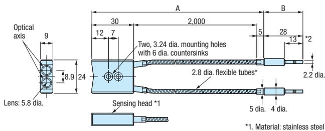
E32-A09H2
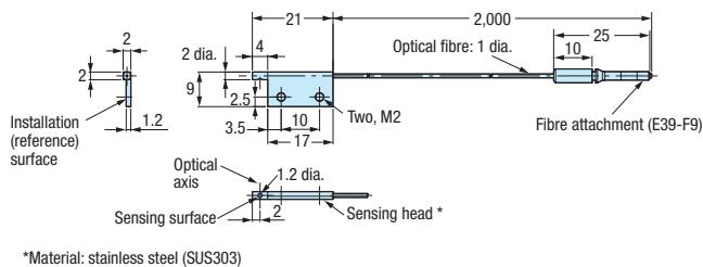
E32-C11N
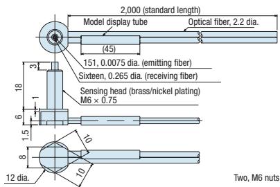
Two, M6 nuts and washers provided.
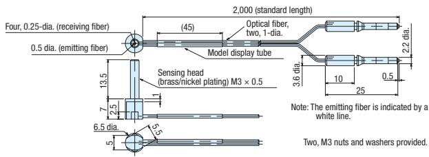
E32-C31N
E32-C42
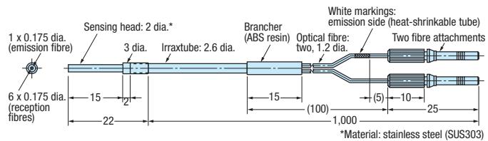
E32-CC200
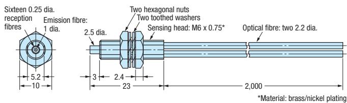
E32-D11, E32-D11U
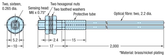
E32-D11L

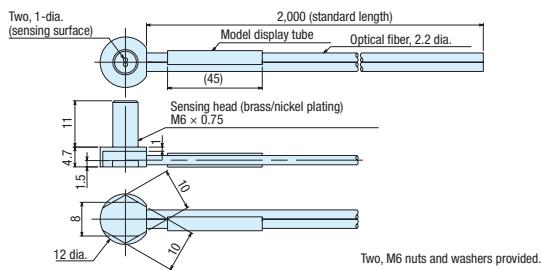
E32-D11N
E32-D12
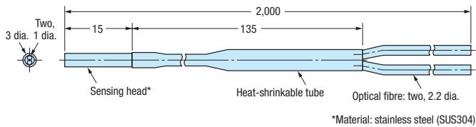
E32-D12F
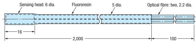
E32-D14F
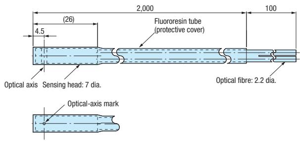
E32-D14L, E32-D14LR
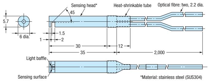
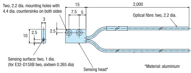
E32-D15X, E32-D15XB, E32-D15XR
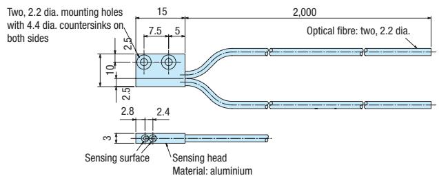
E32-D15Y, E32-D15YR
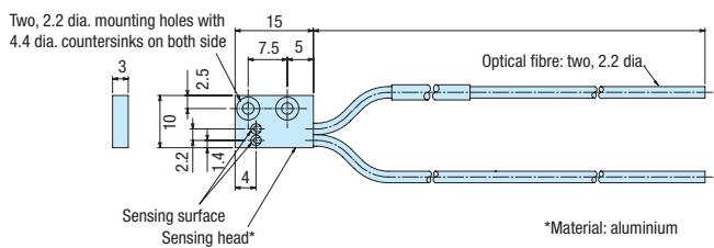
E32-D15Z
E32-D16
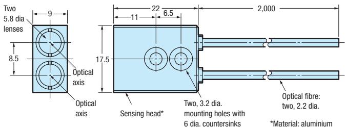
E32-D21
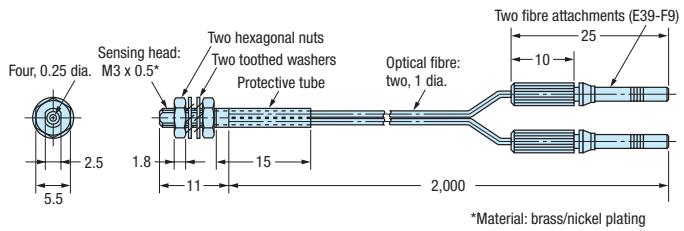
E32-D21B
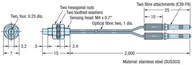
E32-D21L
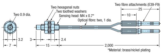
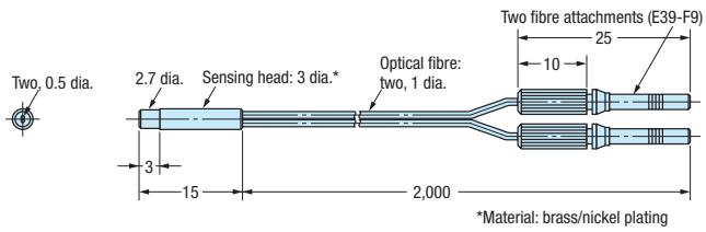
E32-D22, E32-D22R
E32-D22B
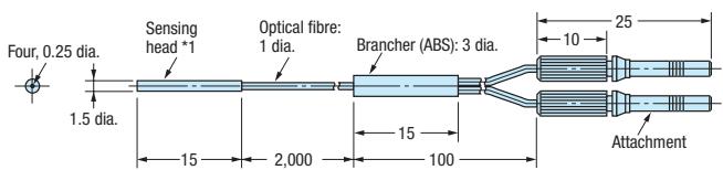
*1. Material: stainless steel (SUS304)
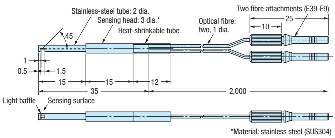
E32-D24, E32-D24R
E32-D32 / E32-D32R
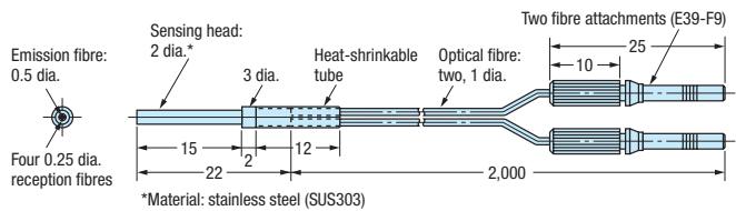
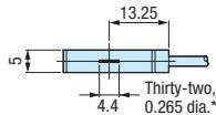
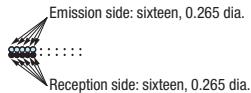
E32-D32L
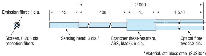
E32-D33
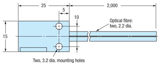
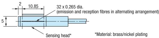
E32-D36P1
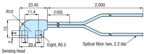
E32-D36T
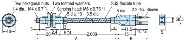
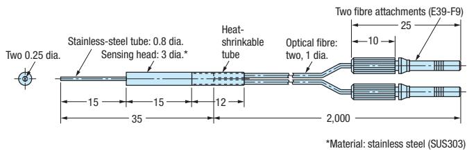
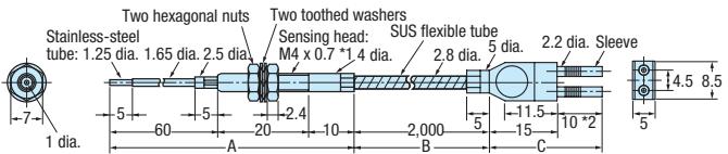
E32-D61-S, E32-D61
Using the E32-D61-S
Using the E32-D61
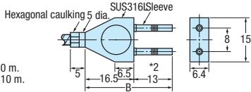
1.Material: stainless steel (SUS303)
3 The diameter is 6 if the fibre length exceeds 10 m .
*4.The diameter is 10 if the fibre length exceeds 10 m .
E32-D73-S, E32-D73
Using the E32-D73-S
Using the E32-D73
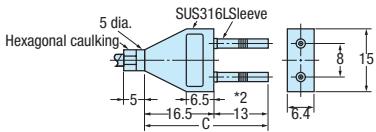
*1. Material: stainless steel (SUS303)
E32-D82F1
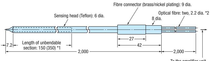
1. ()E32-D82F2
2. The 2-m section of optical fiber on the amplifier unit side is plastic and therefore allows free cutting.

E32-D211, E32-D211R
E32-D331

E32-DC200
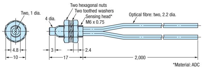
E32-DC200B, E32-DC200BR
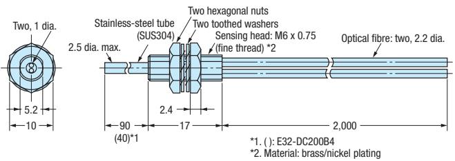
E32-DC200E
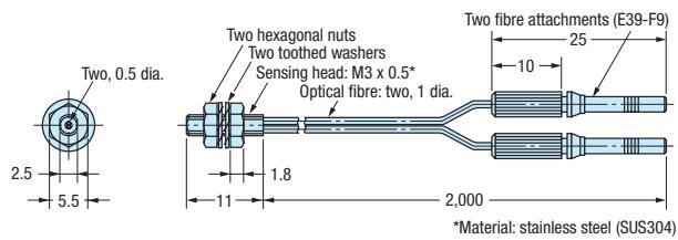
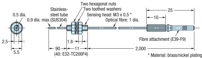
E32-DC200F, E32-DC200FR
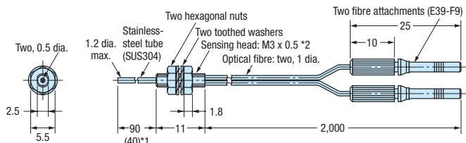
(15) 1 .(:E32-DC200F4 2 Material: stainless steel (SUS304)
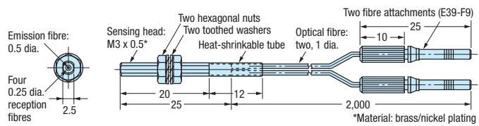
E32-EC31
E32-EC41
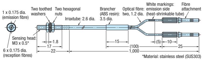
E32-ED11R
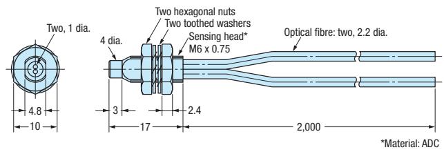
E32-ED21R
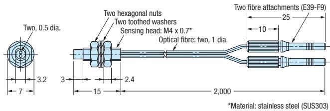
E32-ED51
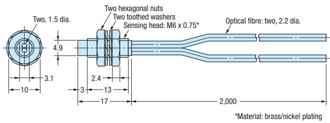
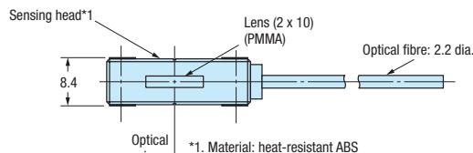
*2. Provided with stickers with slits of width 0.5 and 1 mm (2 of each).
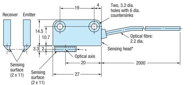
E32-T16J, E32-T16JR

*Material: ABS for the sensing head and PMMA for the prism.
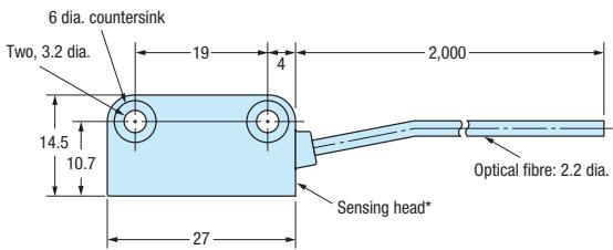
E32-T16P, E32-T16PR
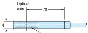
*1.Material:heat-resistant ABS *2.Provided with stickers with slits of width 0.5 and 1mm (2 of each).

E32-T16W, E32-T16WR

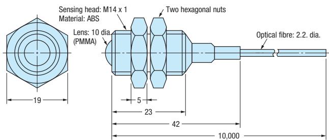
E32-T17L
E32-T21
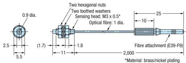
E32-T22, E32-T22R
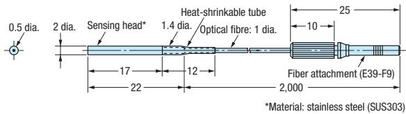
E32-T22B

E32-T22L
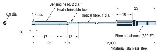
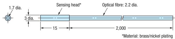
E32-T22S
E32-T24, E32-T24R
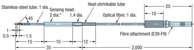
*Material: stainless steel (SUS304)
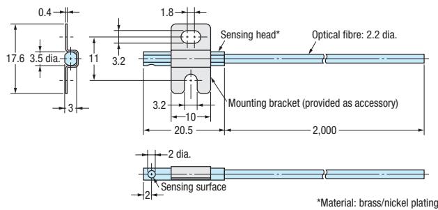
E32-T24S
E32-T51F
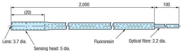
E32-T51V
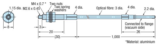
E32-T54
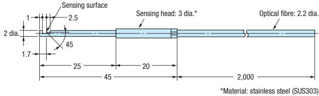
E32-T54V
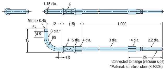
E32-T61-S
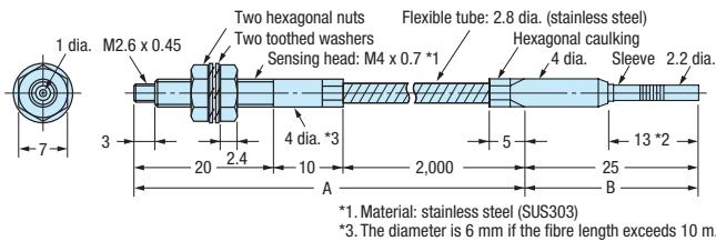
E32-T81F-S
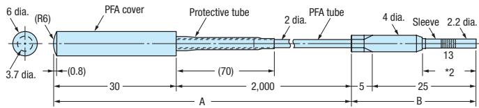
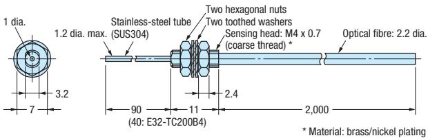
E32-TC200B, E32-TC200BR
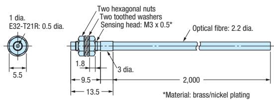
E32-TC200E
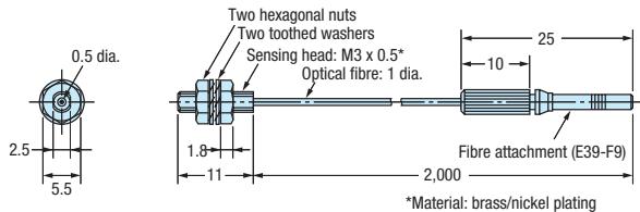
E32-TC200F, E32-TC200FR
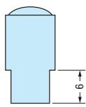
E39-EF1-37
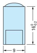
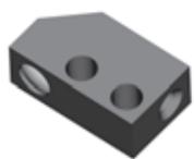
E39-EF51


E39-F1
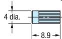
M2.6
Effective depth: 3.8
Spot-facing depth: 0.9
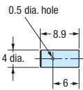
E39-F1V
Material
aluminium for body and optical glass for lens
M2.6x0.45
Effective depth: 3.8
Spot-facing depth: 0.9
E39-F2
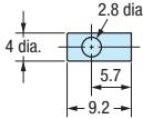
M2.6
Effective depth: 3.2
Spot-facing depth: 0.9
Material:
aluminium for body and
optical glass for lens
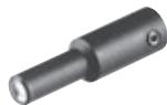
E39-F3A
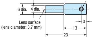
M2 x 2 allen-head set screw (for securing the fiber)

Material: aluminium for body and optical glass for lens
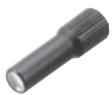
E39-F3A-5
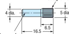
Straight knurling
(lens diameter: 3.7mm )

M3 x 0.5 Effective screw length: 3
Material:
aluminium for body and
optical glass for lens.
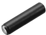
E39-F3B
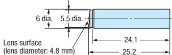

M3 x 0.5 depth: 4.4
Material: aluminium for body and optical glass for lens.
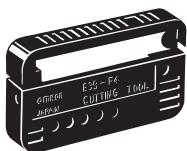
E39-F4
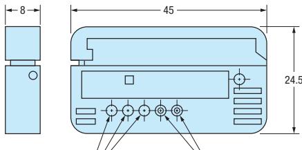
Standard-fiber insertion hole
Thin-fiber insertion hole
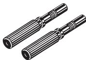
E39-F9
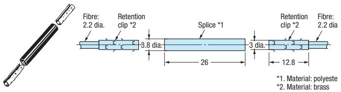
E39-F10
E39-F11
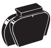
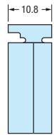
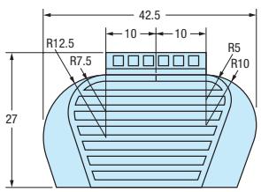
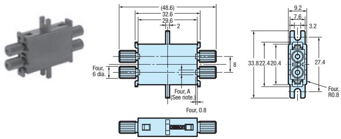
E39-F13, E39-F14, E39-F15
E39-F32A, E39-F32B

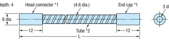
1. Material: brass/nickel plating
2. Material: stainless steel (SUS304)
E39-F32C
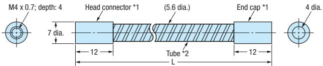
1. Material: brass/nickel plating
2. Material: stainless steel (SUS304)
E39-F32D
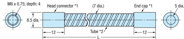
1. Material: brass/nickel plating
2. Material: stainless steel (SUS304)
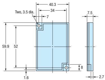
E39-R1S
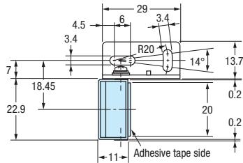
E39-R3

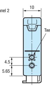
Amplifier
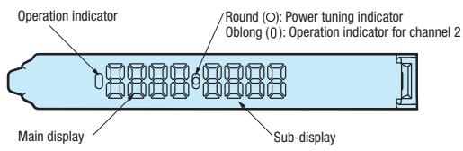
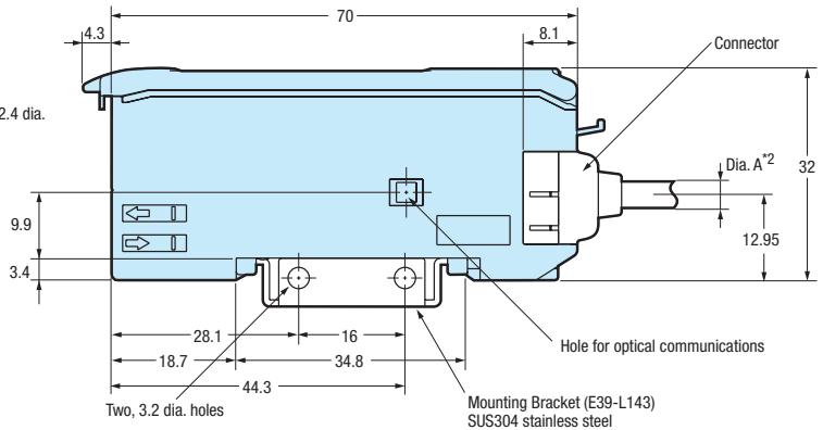
E3X-DA_amplifiers (teachable) - exemplary drawing for connector version
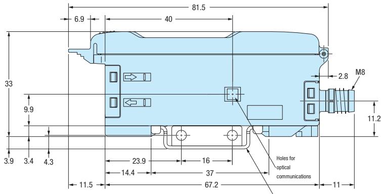
E3X-NA amplifiers (manual adjuster) - exemplary drawing for M8 connector version
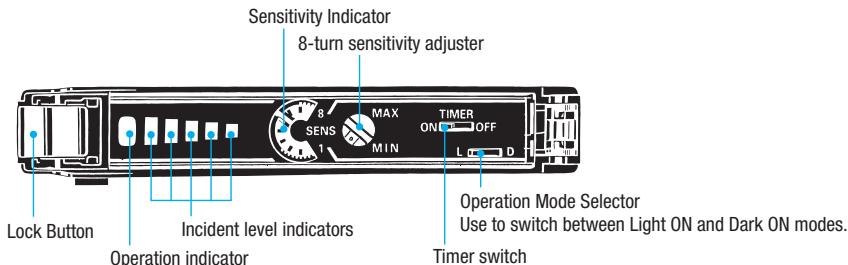
ON: Timer function is ON.
OFF: Timer function is OFF.
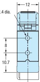
Two, 2.4 dia.
Mounting bracket (E39-L148); Sold separately
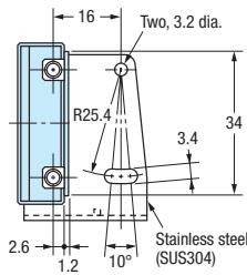
Stainless steel (SUS304)
| Order code | Group |
| E32-A03 2M | Precision detection |
| Special application | |
| E32-A03-1 2M | Square shape |
| E32-A04 2M | Miniature |
| Precision detection | |
| Special application | |
| E32-A04-1 2M | Square shape |
| E32-A09 2M | Precision detection |
| Special application | |
| E32-A09H 2M | Heat resistant |
| E32-A09H2 2M | Heat resistant |
| E32-C11N 2M | Precision detection |
| E32-C31N 2M | Precision detection |
| E32-C42 1M | Precision detection |
| E32-CC200 2M | Precision detection |
| Special application | |
| E32-D11 2M | Robot applications |
| E32-D11L 2M | Longer distance |
| E32-D11N 2M | Standard cylindrical |
| E32-D11U 2M | Chemical resistant |
| E32-D12 2M | Longer distance |
| E32-D12F | Chemical resistant |
| E32-D14F 2M | Chemical resistant |
| E32-D14L 2M | Standard cylindrical |
| E32-D14LR 2M | Standard cylindrical |
| E32-D15X 2M | Square shape |
| E32-D15XB 2M | Robot applications |
| E32-D15XR 2M | Square shape |
| E32-D15Y 2M | Square shape |
| E32-D15YR 2M | Square shape |
| E32-D15Z 2M | Square shape |
| E32-D16 2M | Longer distance |
| E32-D21 2M | Robot applications |
| E32-D21B 2M | Robot applications |
| E32-D21L 2M | Longer distance |
| E32-D22 2M | Miniature |
| E32-D22B 2M | Miniature |
| Robot applications | |
| E32-D22R 2M | Miniature |
| E32-D24 | Miniature |
| E32-D24R 2M | Miniature |
| E32-D32 2M | Miniature |
| Precision detection | |
| E32-D32L 2M | Precision detection |
| E32-D32R 2M | Miniature |
| E32-D33 2M | Miniature |
| E32-D36P1 2M | Area monitoring |
| E32-D36T 2M | Special application |
| E32-D61/ D61-S 2M | Heat resistant |
| E32-D73/ D73-S 2M | Heat resistant |
| E32-D81R/ D81R-S 2M | Heat resistant |
| E32-D82F1 4M | Special application |
| E32-D211 2M | Standard cylindrical |
| E32-D211R 2M | Standard cylindrical |
| E32-D331 2M | Miniature |
| E32-DC200 2M | Standard cylindrical |
| E32-DC200B 2M | Miniature |
| E32-DC200BR | Miniature |
| E32-DC200E 2M | Standard cylindrical |
| E32-DC200F | Miniature |
| E32-DC200FR | Miniature |
| E32-E01 100M | Accessories |
| E32-E01R 100M | Accessories |
| E32-E02 100M | Accessories |
| E32-E02R 100M | Accessories |
| E32-E05 100M | Accessories |
| E32-EC31 2M | Precision detection |
| Special application | |
| E32-EC41 1M | Precision detection |
| Order code | Group |
| E32-ED11R 2M | Standard cylindrical |
| E32-ED21R 2M | Standard cylindrical |
| E32-ED51 2M | Heat resistant |
| E32-EDS24R 2M | Square shape |
| E32-EL24-1 2M | Precision detection |
| Special application | |
| E32-ET11R 2M | Standard cylindrical |
| Special application | |
| E32-ET16WR-1 2M | Area monitoring |
| E32-ET16WR-2 2M | Area monitoring |
| E32-ET21R 2M | Standard cylindrical |
| E32-ET51 2M | Heat resistant |
| E32-ETS10R 2M | Square shape |
| E32-ETS14R 2M | Square shape |
| E32-G14 | Special application |
| E32-L16 2M | Precision detection |
| E32-L24L | Precision detection |
| Special application | |
| E32-L25 | Precision detection |
| E32-L25L | Precision detection |
| Special application | |
| E32-L66 2M | Special application |
| E32-M21 | Area monitoring |
| E32-R16 2M | Longer distance |
| E32-R21 | Standard cylindrical |
| E32-T11 2M | Robot applications |
| E32-T11L 2M | Longer distance |
| E32-T11N 2M | Standard cylindrical |
| E32-T11U 2M | Chemical resistant |
| E32-T12 2M | Miniature |
| E32-T12B | Robot applications |
| E32-T12F | Chemical resistant |
| E32-T12L 2M | Longer distance |
| E32-T12R 2M | Miniature |
| E32-T14 2M | Longer distance |
| E32-T14F 2M | Chemical resistant |
| E32-T14L 2M | Miniature |
| E32-T14LR 2M | Miniature |
| E32-T15X 2M | Square shape |
| E32-T15XB 2M | Robot applications |
| E32-T15Y 2M | Square shape |
| E32-T15YR 2M | Square shape |
| E32-T15Z 2M | Square shape |
| E32-T16 | Area monitoring |
| E32-T16J 2M | Area monitoring |
| E32-T16JR 2M | Area monitoring |
| E32-T16P | Area monitoring |
| E32-T16PR 2M | Area monitoring |
| E32-T16W 2M | Area monitoring |
| E32-T16WR 2M | Area monitoring |
| E32-T17L | Longer distance |
| E32-T21 2M | Robot applications |
| E32-T22 2M | Miniature |
| E32-T22B | Robot applications |
| E32-T22L 2M | Longer distance |
| E32-T22R 2M | Miniature |
| E32-T22S | Precision detection |
| Special application | |
| E32-T24 | Miniature |
| E32-T24R 2M | Miniature |
| E32-T24S | Special application |
| E32-T51F 2M | Chemical resistant |
| E32-T51V 1M | Vaccuum resistant |
| E32-T54 2M | Heat resistant |
| E32-T54V 1M | Vaccuum resistant |
| E32-T61-S 2M | Heat resistant |
| E32-T81F-S 2M | Chemical resistant |
| E32-T81R-S 2M | Heat resistant |
| E32-T84S-S 2M | Heat resistant |
| Order code | Group |
| E32-T84SV 1M | Vaccuum resistant |
| E32-T221B | Robot applications |
| E32-T222 2M | Miniature |
| E32-T222R 2M | Miniature |
| E32-T223R 2M | Miniature |
| E32-TC200 2M | Standard cylindrical |
| E32-TC200A 2M | Longer distance |
| E32-TC200B | Miniature |
| E32-TC200BR | Miniature |
| E32-TC200E 2M | Standard cylindrical |
| E32-TC200F | Miniature |
| E32-TC200FR | Miniature |
| E39-EF1-37 | Accessories |
| E39-EF51 | Accessories |
| E39-F1 | Accessories |
| E39-F10 | Accessories |
| E39-F11 | Accessories |
| E39-F13 | Accessories |
| E39-F14 | Accessories |
| E39-F15 | Accessories |
| E39-F1V | Accessories |
| E39-F2 | Accessories |
| E39-F32A | Accessories |
| E39-F32B | Accessories |
| E39-F32C | Accessories |
| E39-F32D | Accessories |
| E39-F3A | Accessories |
| E39-F3A-5 | Accessories |
| E39-F3B | Accessories |
| E39-F4 | Accessories |
| E39-F9 | Accessories |
| E39-R1S | Accessories |
| E39-R3 | Accessories |
| E3X-CN21 | Accessories |
| E3X-CN21-M1J | Accessories |
| E3X-CN21-M3J-2 | Accessories |
| E3X-DA_AT-S | Advanced amplifiers |
| E3X-DA_S | Advanced amplifiers |
| E3X-DA_SE-S | Easy usage amplifiers |
| E3X-DAC_S | Advanced amplifiers |
| E3X-MDA_ | Advanced amplifiers |
| E3X-NA | Easy usage amplifiers |
| E3X-NA_F | Advanced amplifiers |
| E3X-SD | Easy usage amplifiers |
Precautions
Fiber Units
Installation
Tightening Force
The tightening force applied to the Fiber Unit should be as follows:
Screw-mounting Model Cylindrical Model
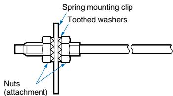
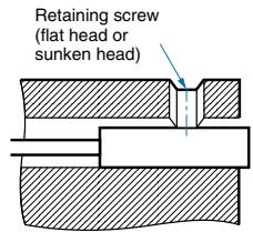
| Fiber Units | Clamping torque |
| M3/M4 screw | 0.78 Nm max. |
| M6 screw/6-mm dia. column | 0.98 Nm max. |
| 1.5-mm dia. column | 0.2 Nm max. |
| 2-mm dia./3-mm dia. column | 0.29 Nm max. |
| E32-T12F 5-mm dia. Teflon model | 0.78 Nm max. |
| E32-D12F 6-mm dia. Teflon model | |
| E32-T16 | 0.49 Nm max. |
| E32-R21 | 0.59 Nm max. |
| E32-M21 | 0.49 Nm max. for up to 5 mm from front end, 0.78 Nm max. for more than 5 mm from front end |
| E32-T16P | 0.29 Nm max. |
| E32-T16PR | |
| E32-T24S | |
| E32-L24L | |
| E32-L25L | |
| E32-T16J | |
| E32-T16JR | |
| E32-ET16W | 0.3 Nm max. |
| E32-ET16WR |
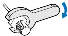
Use a proper-sized wrench.
Cutting Fiber
- Insert a fiber into the Fiber Cutter and determine the length of the fiber to be cut.
- Press down the Fiber Cutter in a single stroke to cut the fiber.
- Cut a thin fiber as follows:
| ① | An attachment is temporarily fitted to a thin fiber be-fore shipment. | Thin fiber attachment (E39-F9) Temporarily fitted |
| ② | Secure the attachment after adjusting the position of it in the direction indicated by the arrow. | |
| ③ | Insert the fiber to be cut into the E39-F4. | E39-F4 fiber cutter Three holes for standard fiber (2.2-mm dia.) Two holes for thin fiber |
| ④ | Finished state (proper cutting state) | Approx. 0.5 mm Insertion direction Note: Insert the fiber in the direction indicated by the arrow. |
Connection
- Do not pull or press the fiber units. The fiber units withstand tensile or compression force of 9.8 ~N or 29.4 ~N maximum.
- Do not bend the fiber unit beyond the permissible bending radius given under Ordering Information.
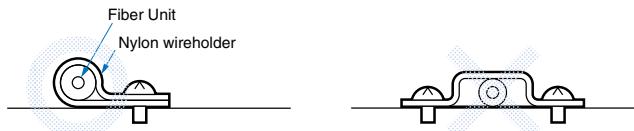
- Do not bend the edge of the fiber units (excluding the E32-T□R and E32-D□R).
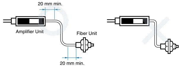
- Do not apply excess force on the fiber units.
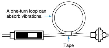
- The fiber head may break due to excessive vibration. A one-turn loop may reduce the effect of vibrations:
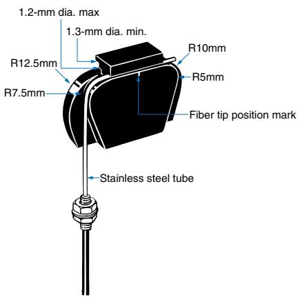
E39-F11 Sleeve Bender
- The bending radius of the stainless steel tube should be as large as possible. The smaller the bending radius becomes, the shorter the sensing distance will be.
- Insert the tip of the stainless steel tube to the sleeve bender and bend the stainless steel tube slowly along the curve of the sleeve bender (refer to the figure).

Heat-resistant fibers
- The fiber connector E39-F10 cannot be used for extension.
E32-T14/E32-G14
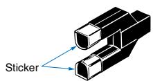
The presence of a reflective object at the front ends of the lenses may place the unit in an incident state. In this case, apply the supplied black stickers to the front ends of the lenses.
Supplied slit for E32-T16
When using the supplied slit, peel off the back paper and apply it along the outline of the sensing surface. The slit is recommended in applications where saturation occurs.
E32-M21
To prevent mutual interference sufficient distance between the four sensing heads has to be ensured.
Adjustment
E32-G14
Due to the short distance between the sensor heads, two-point teaching (with and without object) is recommended.
Accessories
Protective Spiral Tubes
- Insert a fiber to the protective spiral tube from the head connector side (screwed) of the tube.
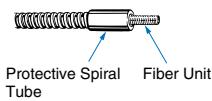
- Push the fiber into the protective spiral tube. The tube should be straight so that the fiber is not twisted when inserted. Then turn the end cap of the spiral tube.
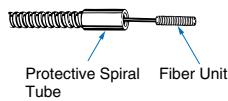
- Secure the protective spiral tube at a suitable place with the attached nut.
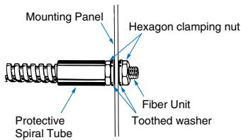
- Use the attached saddle to secure the end cap of the protective spiral tube. To secure the protective spiral tube at a position other than the end cap, apply tape to the tube so that the portion becomes thicker in diameter.
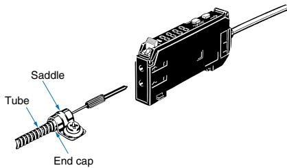
E39-F10 Fiber Connector
Fit the connector in the following procedure.
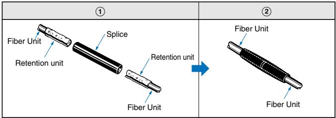
- The fiber units should be as close as possible when they are connected. Sensing distance will be reduced by approximately 25% when fibers are connected.
Only 2.2mm dia. fibers can be connected.
Amplifier Unit
Installation
Operation after Turning Power ON
The Amplifier Unit is ready to operate within 200 ms after the power supply is turned ON. If the Sensor and load are connected to power supplies separately, be sure to turn ON the power supply to the Sensor first.
Mounting
- Connecting and Disconnecting Connectors
Mounting Connectors
- Insert the Master or Slave Connector into the Amplifier Unit until it clicks into place.
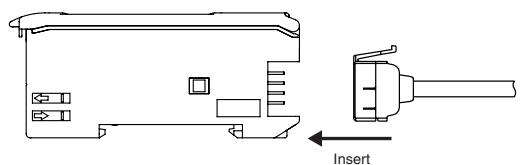
- Attach the protector seals (provided as accessories) to the sides of master and slave connectors that are not connected.
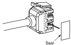
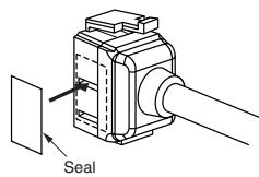
Note: Attach the seals to the sides with grooves
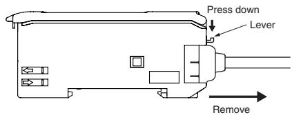
Removing Connectors
- Slide the slave Amplifier Unit(s) for which the Connector is to be removed away from the rest of the group.
- After the Amplifier Unit(s) has been separated, press down on the lever on the Connector and remove it. (Do not attempt to remove Connectors without separating them from other Amplifier Units first.)
- Joining and Removing Amplifier Units
Joining Amplifier Units
- Mount the Amplifier Units one at a time onto the DIN track.
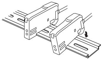
- Slide the Amplifier Units together, line up the clips, and press the Amplifier Units together until they click into place.
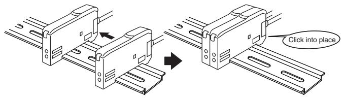
Separating Amplifier Units
Slide Amplifier Units away from each other, and remove from the DIN track one at a time. (Do not attempt to remove Amplifier Units from the DIN track without separating them first.)
Note 1. The specifications for ambient temperature will vary according to the number of Amplifier Units used together. For details, refer to Ratings/Characteristics.
2. Always turn OFF the power supply before joining or separating Amplifier Units.
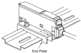
- Mounting the End Plate (PFP-M)
An End Plate should be used if there is a possibility of the Amplifier Unit moving, e.g., due to vibration. If a Mobile Console is going to be mounted, connect the End Plate in the direction shown in the following diagram.
- Mounting the Mobile Console Head
Leave a gap of at least 20mm between the nearest Amplifier Unit and the Mobile Console head.

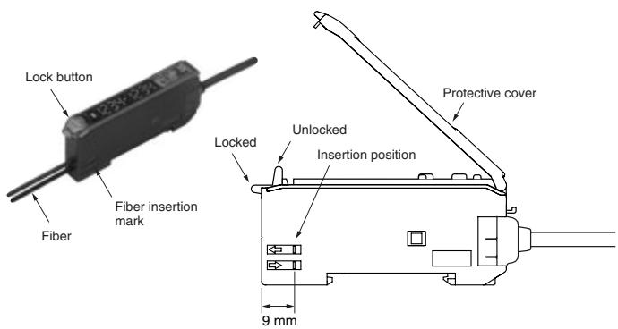
- Fiber Connection
The E3X Amplifier Unit has a lock button for easy connection of the Fiber Unit. Connect or disconnect the fibers using the following procedures:
1. Connection
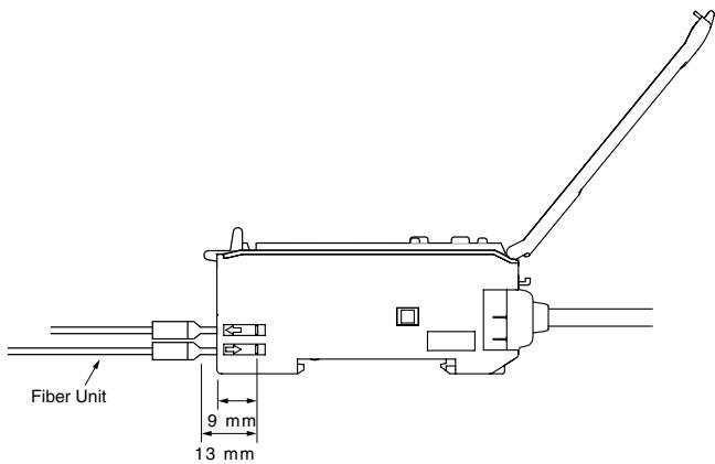
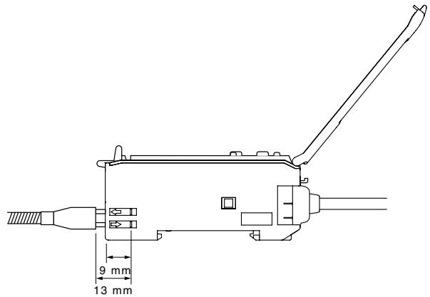
Open the protective cover, insert the fibers according to the fiber insertion marks on the side of the Amplifier Unit, and lower the lock button.
Fibers with E39-F9 Attachment
Fibers That Cannot Be Free-Cut (with Sleeves)
Note: For complete precautions and installation instructions refer to individual amplifier datasheets.
2. Disconnecting Fibers
Remove the protective cover and raise the lock button to pull out the fibers.
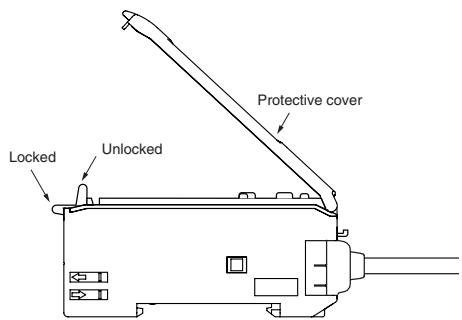
Note 1. To maintain the fiber properties, confirm that the lock is released before removing the fibers.
2. Be sure to lock or unlock the lock button within an ambient temperature range between -10^ and 40^ .
- Protective Cover
Always keep the protective cover in place when using the Amplifier Unit.
Cat. No. E56E-EN-01A
In the interest of product improvement, specifications are subject to change without notice.
OMRON EUROPE B.V.
Wegalaan 67-69,
- Features
- Long operational lifetime
- Easy to set up and adjust
- High accuracy in smallest size
- Standard cylindrical fiber sensor heads
- Square shape fiber sensor heads
- Miniature fiber sensor heads
- Longer distance fiber sensor heads
- Chemical resistant fiber sensor heads
- Heat resistant fiber sensor heads
- Vacuum resistant fiber sensor heads
- Ordering information
- Robot application fiber sensor heads
- Precision detection fiber sensor heads
- Area monitoring fiber sensor heads
- Special application fiber sensor heads
- Digital fiber amplifier with one button teaching
- Digital fiber amplifier for basic applications
- High functionality digital fiber amplifier
- Specifications
- Digital fiber amplifier with active threshold control for dust and dirt compensation
- Fast response digital amplifier with potentiometer
- 2-in-1 Digital fiber amplifier
- E3X-DAC-S colour (RGB) digital fiber amplifier
- E32-D73-S, E32-D73
- Amplifier
- Precautions
- Fiber Units
- Tightening Force
- Cutting Fiber
- Connection
- E39-F11 Sleeve Bender
- Heat-resistant fibers
- E32-T14/E32-G14
- Supplied slit for E32-T16
- E32-M21
- Adjustment
- E32-G14
- Accessories
- Protective Spiral Tubes
- E39-F10 Fiber Connector
- Amplifier Unit
- Installation
- Operation after Turning Power ON
- Mounting
- Mounting Connectors
- Removing Connectors
- Joining Amplifier Units
- Separating Amplifier Units
- - Mounting the End Plate (PFP-M)
- - Mounting the Mobile Console Head
- - Fiber Connection
- Connection
- Disconnecting Fibers
- - Protective Cover
- OMRON EUROPE B.V.
Brand : OMRON
Model : E3X
Category : Optical sensor