
D4CC - Position Sensors OMRON - Free user manual and instructions
Find the device manual for free D4CC OMRON in PDF.


| Product type | Position sensor (miniature limit switch) |
| Brand | OMRON |
| Model | D4CC |
| Rated voltage | 125 VAC or 30 VDC |
| Rated current | 1 A (resistive load) |
| Protection rating | IP67 |
| Mechanical life | 10,000,000 operations min. |
| Electrical life | 200,000 operations min. (1 A, 125 VAC) |
| Ambient temperature | -10°C to 70°C (no freezing) |
| Ambient humidity | 95% max. |
| Weight | Approx. 120 g (D4CC-1002 model) |
| Body material | Molded resin |
| Available actuator | Plunger, roller, lever, plastic rod, central lever |
| Operation indicator | Built-in LED (optional, turns off when actuated) |
| Connection | M12 connector, 4-conductor cable |
| Mounting | Via 5.2 mm holes or M5 screws |
| Group mounting | Up to 6 switches (with mounting guide) |
| Insulation resistance | 100 MΩ min. (500 VDC) |
| Dielectric strength | 1000 VAC 1 min between terminals, 1500 VAC 1 min live parts/ground |
| Shock resistance | Destruction: 1000 m/s² min., Malfunction: 500 m/s² min. |
| Vibration resistance | Malfunction: 10 to 55 Hz, 1.5 mm double amplitude |
Frequently Asked Questions - D4CC OMRON
User questions about D4CC OMRON
0 question about this device. Answer the ones you know or ask your own.
Ask a new question about this device
Download the instructions for your Position Sensors in PDF format for free! Find your manual D4CC - OMRON and take your electronic device back in hand. On this page are published all the documents necessary for the use of your device. D4CC by OMRON.
USER MANUAL D4CC OMRON
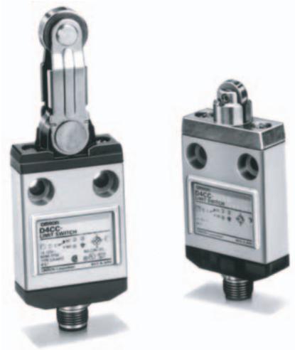
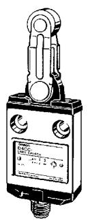
Many Models Including Roller Lever Switches are Only 16-mm Thick with Connector
- New center roller lever models that enable ganged mounting of up to 6 Switches.
- Cable connectors for easy Switch replacement.
- Triple-seal construction for plungers to provide IEC IP67, UL, and CSA (type 3, 4, 13) degree of protection.
- Operation indicators available for easy monitoring (standard indicator is lit when Switch is not operating).
natural_image
Two industrial D4CC limit switch devices shown from different angles (no visible text or symbols on the devices themselves)
Model Number Structure
■ Model Number Legend
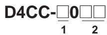
1. Rated Load
(These codes are different from suffix codes of the D4C)
1: 1 A at 125 VAC
2: 1 A at 125 VAC (with LED indicator)
3: 1 A at 30 VDC
4: 1 A at 30 VDC (with LED indicator)
2. Actuator
01: Pin plunger
02: Roller plunger
03: Crossroller plunger
10: Bevel plunger
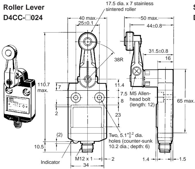
24: Roller lever
31: Sealed pin plunger
32: Sealed roller plunger
33: Sealed crossroller plunger
41: Panel mount pin plunger
42: Panel mount roller plunger
43: Panel mount crossroller plunger
50: Plastic rod
60: Center roller lever
Note: With standard models, the operation indicator turns OFF when the switch operates. If models with operation indicators that turn ON when the switch operates are required, add "-B" to the end of the model number.
Ordering Information
■ List of Models
Limit Switches
| Actuator | 1 A at 125 VAC | 1 A at 30 VDC | ||
| Without indicator | With indicator | Without indicator | With indicator | |
Pin plunger plunger | D4CC-1001 | D4CC-2001 | D4CC-3001 | D4CC-4001 |
| Roller[76GB]plunger | D4CC-1002 | D4CC-2002 | D4CC-3002 | D4CC-4002 |
| Crossroller[SS83]plunger | D4CC-1003 | D4CC-2003 | D4CC-3003 | D4CC-4003 |
| Bevel[GB/T]plunger | D4CC-1010 | D4CC-2010 | D4CC-3010 | D4CC-4010 |
High-sensitivitroller lever  | D4CC-1024 | D4CC-2024 | D4CC-3024 | D4CC-4024 |
| Sealedpin[8'5B]plunger | D4CC-1031 | D4CC-2031 | D4CC-3031 | D4CC-4031 |
Sealed roller plunger plunger | D4CC-1032 | D4CC-2032 | D4CC-3032 | D4CC-4032 |
| Sealedcrossroller[32SW]plunger | D4CC-1033 | --- | D4CC-3033 | D4CC-4033 |
Panel mount pin plunger pin plunger | D4CC-1041 | D4CC-2041 | D4CC-3041 | D4CC-4041 |
| Panel mount[5X03]roller plunger | D4CC-1042 | D4CC-2042 | D4CC-3042 | D4CC-4042 |
| Panel mountcrossroller[4A4TZ]plunger | D4CC-1043 | --- | D4CC-3043 | D4CC-4043 |
| Plasticrod[22C8] | D4CC-1050 | D4CC-2050 | D4CC-3050 | D4CC-4050 |
| Centerroller[4H3C3] | D4CC-1060 | D4CC-2060 | D4CC-3060 | D4CC-4060 |
Note: 1. The meaning of suffix codes in the D4CC model numbers is different from that in the D4C model numbers.
2. Refer to the following table for cable plugs.
Accessories (Order Separately)
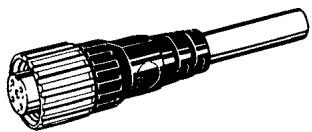
Plugs
| Type | Appearance | No. of conductors | Cable length | Model |
| VAC | Straight 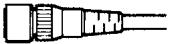 | 4 | 1 m | XS2F-A421-C90-A |
| 2 m | XS2F-A421-D90-A | |||
| 5 m | XS2F-A421-G90-A | |||
| 10 m | XS2F-A421-J90-A | |||
| VDC | 1 m | XS2F-D421-C80-A | ||
| 2 m | XS2F-D421-D80-A | |||
| 5 m | XS2F-D421-G80-A | |||
| 10 m | XS2F-D421-J80-A |
Note: Please contact your local OMRON sales office for details.
Special Mounting Plate
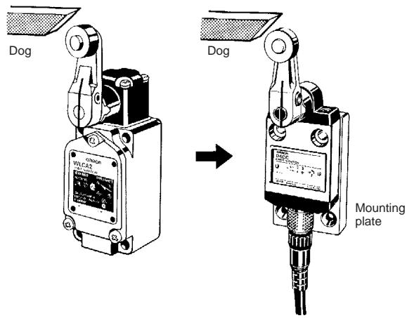
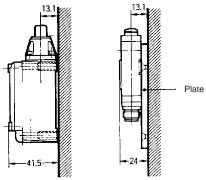
It is possible to replace an WL Limit Switch with a D4CC Limit Switch mounted on this plate without changing the position of the dog or cam.
The following is the conversion table:
| WL | D4C | Plate model |
| Top plunger: WLD | Plunger: D4CC-☐001 | D4C-P001 |
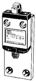
| Top roller plunger: WLD2 | Roller plunger: D4CC-☐002 | D4C-P002 |
| Roller lever: WLG2 | Roller lever: D4CC-☐024 | D4C-P020 |
Example
Remarks
There is no difference in mounting pitch between the Mounting Plate and the WL. The mounting depth of the D4CC with the Mounting Plate attached is, however, shorter than that of the panel-mounted WL.
Specifications
■ Approved Standards
| Agency | Standard | File No. |
| UL | UL508 | E76675 |
| CSA | CSA C22.2 No. 14 | LR45746 |
■ Approved Standard Ratings
UL-CSA
D4CC-1, D4CC-2
D150
| Rated voltage | Carry current | Current | Volt-amperes | ||
| Make | Break | Make | Break | ||
| 120 VAC | 1.0 A | 3.6 A | 0.6 A | 432 VA | 72 VA |
■ Ratings
| Rated voltage | Non-inductive load | Inductive load | ||||||
| Resistive load | Lamp load | Inductive load | Motor load | |||||
| NC | NO | NC | NO | NC | NO | NC | NO | |
| 125 VAC | 1 A | 1 A | 1 A | 0.7 A | 1 A | 1 A | 1 A | 1 A |
| 30 VDC | 1 A | 1 A | 1 A | 1 A | 1 A | 1 A | 1 A | 1 A |
Note: 1. The above current ratings are for steady-state current.
2. Inductive loads have a power factor of 0.4 min. (AC) and a time constant of 7 ms max. (DC).
3. Lamp loads have an inrush current of 10 times the steady-state current.
4. Motor loads have an inrush current of 6 times the steady-state current.
D4CC-3, D4CC-4, 1 A at 30 VDC
| Inrush current | NC | 5 A max. |
| NO | 2.5 A max. |
■ Characteristics
| Degree of protection | IP67 |
| Durability (see note 2) | Mechanical: 10,000,000 operations min.Electrical: 200,000 operations min. (1 A at 125 VAC, resistive load) |
| Operating speed | Plunger: 0.1 mm to 0.5 m/sRoller lever: 1 mm to 1 m/s |
| Operating frequency | Mechanical: 120 operations/minElectrical: 30 operations/min |
| Rated frequency | 50/60 Hz |
| Insulation resistance | 100 MΩ min. (at 500 VDC) |
| Contact resistance (initial) | 100 mΩ max. |
| Dielectric strength | 1,000 VAC, 50/60 Hz for 1 min between terminals of same polarity1,500 VAC, 50/60 Hz for 1 min between current-carrying metal parts and ground, and between each terminal and non-current-carrying metal part |
| Vibration resistance | Malfunction: 10 to 55 Hz, 1.5-mm double amplitude (see note 3) |
| Shock resistance | Destruction: 1,000 m/s2 min.Malfunction: 500 m/s2 min. |
| Ambient temperature | Operating: -10°C to 70°C (with no icing) |
| Ambient humidity | Operating: 95% max. |
| Weight | Approx. 120 g (in the case of D4CC-1002) |
Note: 1. The above figures are initial values.
2. The values are calculated at an operating temperature of 5^ C to 35^ C, and an operating humidity of 40% to 70%. Contact your OMRON sales representative for more detailed information on other operating environments.
3. Excluding plastic rod models.
Leakage Current (for Switches with Indicators)
The leakage current and resistance of Switches with indicators are as follows:
| Item | D4CC-2□□□ | D4CC-4□□□ |
| Voltage | 125 VAC | 30 VDC |
| Leakage current | 1.0 mA | 1.0 mA |
| Resistive value | 150 kΩ | 30 kΩ |
■ Operating Characteristics
| Model | D4CC-□001 | D4CC-□002 | D4CC-□003 | D4CC-□010 | D4CC-□024 |
| OF max. | 11.77 N | 11.77 N | 11.77 N | 11.77 N | 5.69 N |
| RF min. | 4.41 N | 4.41 N | 4.41 N | 4.41 N | 1.47 N |
| PT max. | 1.8 mm | 1.8 mm | 1.8 mm | 1.8 mm | 10 ± 3^ |
| OT min. | 3 mm | 3 mm | 3 mm | 3 mm | 50^ |
| MD max. | 0.2 mm | 0.2 mm | 0.2 mm | 0.2 mm | 3^ |
| OP | 15.7 ± 1 mm | 28.5 ± 1 mm | 28.5 ± 1 mm | 28.5 ± 1 mm | --- |
| Model | D4CC-□031 | D4CC-□032 | D4CC-□033 | D4CC-□041 | D4CC-□042 | D4CC-□043 |
| OF max. | 17.65 N | 17.65 N | 17.65 N | 11.77 N | 11.77 N | 11.77 N |
| RF min. | 4.41 N | 4.41 N | 4.41 N | 4.41 N | 4.41 N | 4.41 N |
| PT max. | 1.8 mm | 1.8 mm | 1.8 mm | 1.8 mm | 1.8 mm | 1.8 mm |
| OT min. | 3 mm | 3 mm | 3 mm | 3 mm | 3 mm | 3 mm |
| MD max. | 0.2 mm | 0.2 mm | 0.2 mm | 0.2 mm | 0.2 mm | 0.2 mm |
| OP | 24.9±1 mm | 34.3±1 mm | 34.3±1 mm | 31.2±1 mm | 36.8±1 mm | 36.8±1 mm |
| TT (reference value) | (5) mm | (5) mm | (5) mm | (5) mm | (5) mm | (5) mm |
| Model | D4CC-□050 | D4CC-□060 |
| OF max. | 1.47 N | 6.67 N |
| RF min. | --- | 1.47 N |
| PT max. | 15° | 10±3° |
| OT min. | --- | 50° |
| MD max. | --- | 3° |
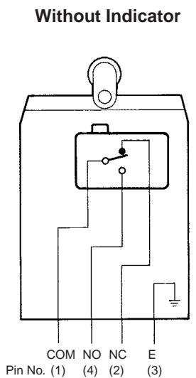
■ Contact Form
AC Switches (D4CC-10□□, 20□□)
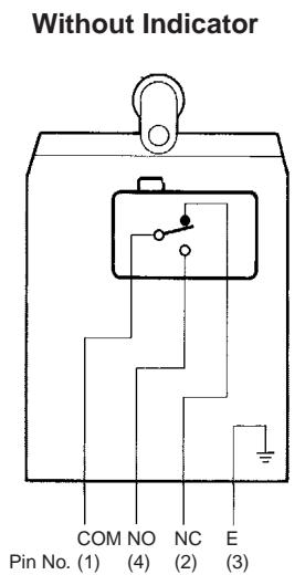
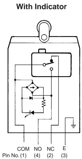
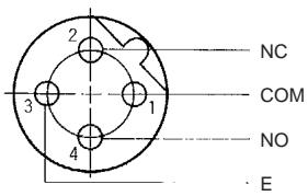
Note: The indicators of these models are lit when the Switches are not actuated. When the Switches are actuated, the indicator are off.
Note 1. "Lights when operated" means that when the actuator is turned or pushed and the Limit Switch contact leaves the NC side, the indicator lights.
2. "Lights when not in operation" means that when the actuator is in the free position, the indicator is lit, and when the actuator is turned or pushed and the contact comes into contact with the NO side, the indicator turns OFF.
DC Switches (D4CC-30□□, 40□□)

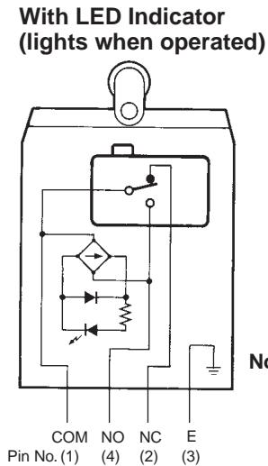
With LED Indicator (lights when operated)
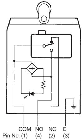
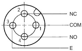
Note: The indicators of these models are lit when the Switches are not actuated. When the Switches are actuated, the indicator are off.
Note 1. "Lights when operated" means that when the actuator is turned or pushed and the Limit Switch contact leaves the NC side, the indicator lights.
2. "Lights when not in operation" means that when the actuator is in the free position, the indicator is lit, and when the actuator is turned or pushed and the contact comes into contact with the NO side, the indicator turns OFF.
Plugs
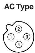
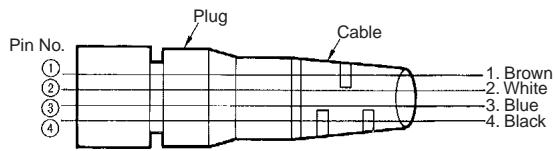
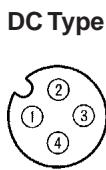
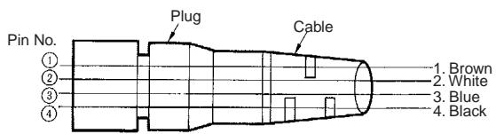
Nomenclature
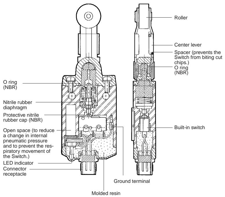
Dimensions
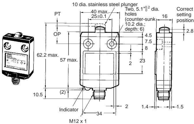
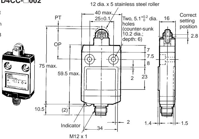
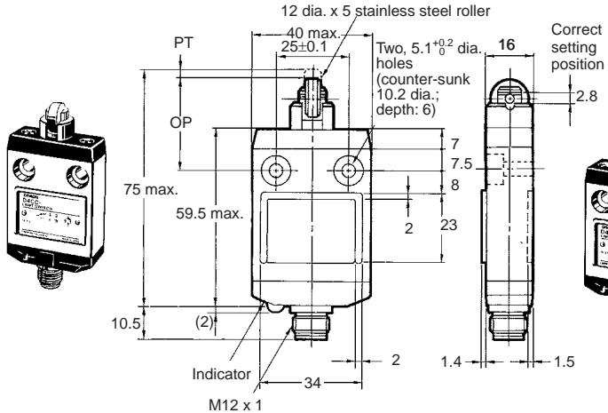
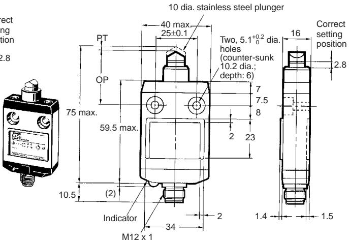
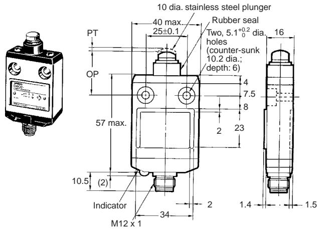
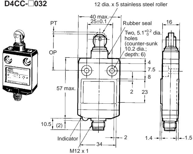
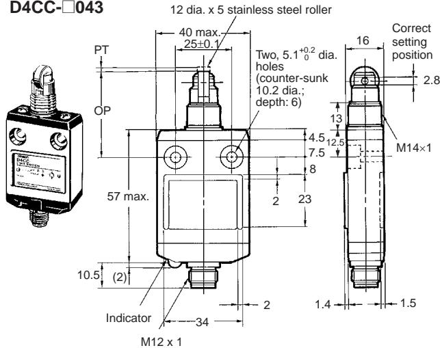
Note: 1. All units are in millimeters unless otherwise indicated.
- The □ in each model number is replaced with the code expressing the rated load of the model. Refer to Ordering Information.
- Unless otherwise specified, a tolerance of ±0.4 mm applies to all dimensions.
Limit Switches
Pin Plunger
D4CC-□001
Roller Plunger
D4CC-□002
Crossroller Plunger
D4CC-□003
Bevel Plunger
D4CC-□010
Sealed Pin Plunger
D4CC-□031
Sealed Roller Plunger
Sealed Crossroller Plunger
D4CC-□033
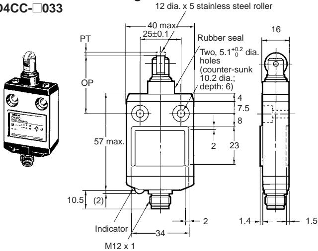
Panel Mount Pin Plunger
D4CC-□041
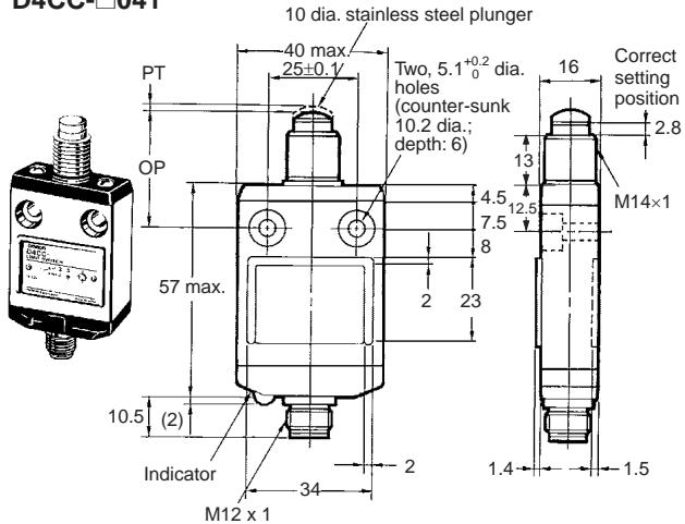
Panel Mount Roller Plunger
D4CC-□042

Panel Mount Crossroller Plunger
D4CC-□043
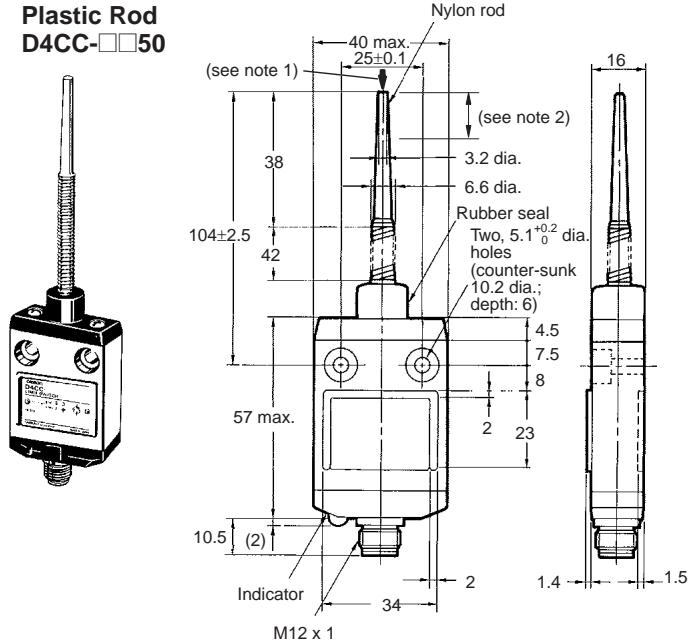
Note: 1. Operation is possible in any direction except parallel to the axis ↓.
2. The ideal range for operation is between the tip of the rod and 1/3 of the length of the actuator.
Center Roller Lever
D4CC-□□60
natural_image
Technical line drawing of a mechanical pressure sensor device (no text or symbols visible)
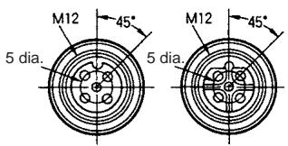
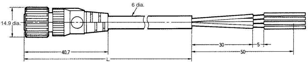
Plugs
XS2F-D421-☐80-A (DC)
XS2F-A421-□90-A (AC)
(Straight Type)
natural_image
Technical line drawing of a mechanical connector or connector (no text or symbols)| Model | Cable length (L) |
| XS2F-D421-C□-A | 1 m |
| XS2F-D421-D□-A | 2 m |
| XS2F-D421-G□-A | 5 m |
| XS2F-D421-J□-A | 10 m |
Special Mounting Plates
(Limit Switches are not attached to the Plates.)
D4C-P001 (For D4CC-□001)
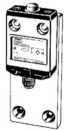
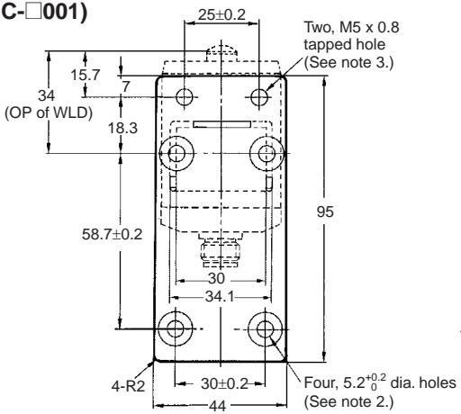
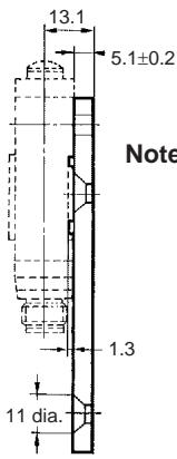
Note: 1. Four hexagonal flat head bolts (M5 x 0.8, length: 10) and two Allen-head bolts (M5 x 0.8, length: 15) are included.
2. All the holes with 5.2^+0.2/_0 dia. must be used with M5 x 10 Allen-head bolts.
3. All the M5-tapped holes must be used with M5 hexagonal flat head bolts.
D4C-P002 (For D4CC-□002)
natural_image
Illustration of a mechanical control device with no visible text or symbols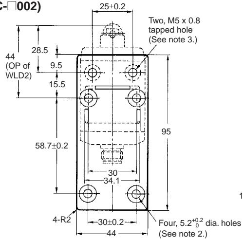
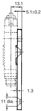
Note: 1. Four hexagonal flat head bolts (M5 x 0.8, length: 10) and two Allen-head bolts (M5 x 0.8, length: 15) are included.
2. All the holes with 5.2^+0.2/_0 dia. must be used with M5 x 10 Allen-head bolts.
3. All the M5-tapped holes must be used with M5 hexagonal flat head bolts.
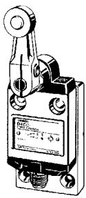
D4C-P020 (For D4CC-□024)
natural_image
Technical line drawing of a mechanical switch or lever device (no text or symbols visible)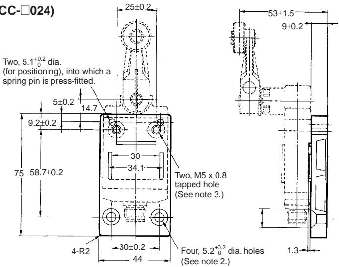
Note: 1. Four hexagonal flat head bolts (M5 x 0.8, length: 10), two Allen-head bolts (M5 x 0.8, length: 15), and two spring pins (4 x 14) are included.
2. All the holes with 5.2^+0.2/_0 dia. must be used with M5 x 10 Allen-head bolts.
3. All the M5-tapped holes must be used with M5 hexagonal flat head bolts.
■ Correct Use
Mounting
Make sure that the plate to which the D4CC is mounted is flat. If the plate is warped or has protruding parts, the D4CC may not malfunction.
Mounting Holes
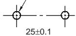
Two, 5.2-dia. or
M5 screw holes
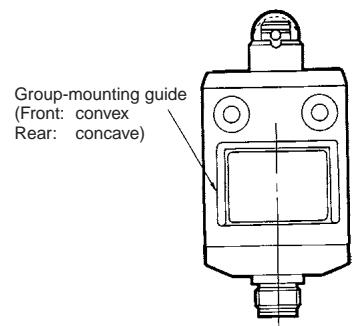
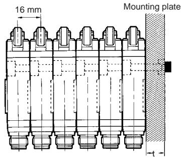
A maximum of 6 Switches may be group-mounted. In this case, pay attention to the mounting direction so that the convex part of the group-mounting guide on one Switch fits into the concave part of the guide on the other Switch as shown in the figure below. For group mounting, the mounting panel must have a thickness (t) of 6 mm min.
Group Mounting
Tightening Torque
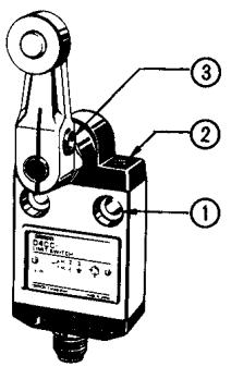
Be sure to tighten each screw to the proper tightening torque as shown in the table.
| No. | Type | Torque |
| 1 | M5 Allen-head bolt | 4.90 to 5.88 N·m |
| 2 | M3.5 head mounting screw | 0.78 to 0.88 N·m |
| 3 | M5 Allen-head bolt | 4.90 to 5.88 N·m |
Note: By removing the two screws from the head, the head direction can be rotated 180^ . After changing the head direction, re-tighten to the torque specified above. Be careful not to allow any foreign substance to enter the Switch.
Plug Tightening
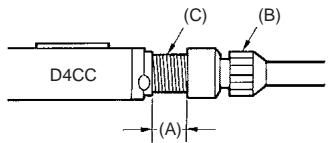
Connect the plug connector (B) to the connector threads of the D4CC. Then firmly turn the plug connector by hand so that the connector threaded portion (C) will be completely covered by the plug connector (B) so that space (A) will be almost 0. Do not use any tools, such as pliers, to tighten the plug connector, otherwise the plug connector may become damaged. Make sure, however, that the plug connector is tightened securely, otherwise the rated degree of protection of the D4CC may not be maintained. Furthermore, the plug connector may be loosened by vibration.
Properly Tightened Connector
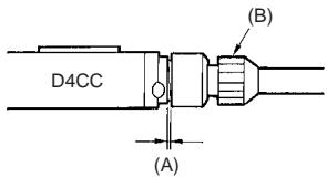
Operation
Operation method, shapes of cam and dog, operating frequency, and overtravel have a significant effect on the service life and precision of a Limit Switch. For this reason, the dog angle must be 30^ max., the surface roughness of the dog must be 6.3S min. and hardness must be Hv400 to 500.
To allow the plunger-type actuator to travel properly, adjust the dog and cam to the proper setting positions. The proper position is where the plunger groove fits the bushing top.
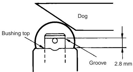
To allow the roller lever-type actuator to travel properly, adjust the dog and cam so that the arrow head is positioned between the two convex markers as shown below.
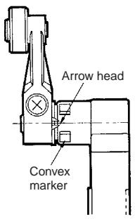
Others
If failures, such as reset failures, in the plunger model are possible, use a model that has a rubber cap.
Do not expose the Switch to water exceeding 70^ C or use it in steam.
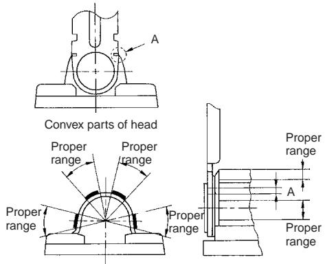
Properly adjust the stroke of the center roller lever along with the dog or cam so that the concave part (A) of the head is located between the convex parts of the head as shown below when the center roller lever is pressed by the dog or cam.
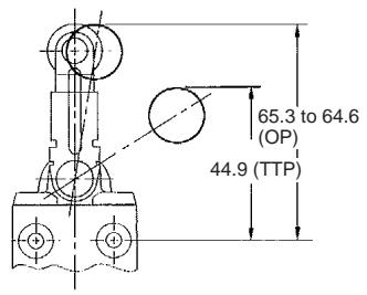
Refer to the following to adjust the stroke of the lever based on the mounting hole level.
ALL DIMENSIONS SHOWN ARE IN MILLIMETERS. To convert millimeters into inches, multiply by 0.03937. To convert grams into ounces, multiply by 0.03527.
Cat. No. C116-E1-02
In the interest of product improvement, specifications are subject to change without notice.
- Many Models Including Roller Lever Switches are Only 16-mm Thick with Connector
- Model Number Structure
- ■ Model Number Legend
- Rated Load
- Actuator
- Ordering Information
- ■ List of Models
- Accessories (Order Separately)
- Special Mounting Plate
- Remarks
- Specifications
- ■ Approved Standard Ratings
- UL-CSA
- ■ Ratings
- Leakage Current (for Switches with Indicators)
- ■ Contact Form
- Nomenclature
- Dimensions
- Limit Switches
- Plugs
- Special Mounting Plates
- (Limit Switches are not attached to the Plates.)
- ■ Correct Use
- Mounting
- Mounting Holes
- Group Mounting
- Tightening Torque
- Plug Tightening
- Properly Tightened Connector
- Operation
- Others
Brand : OMRON
Model : D4CC
Category : Position Sensors