
TPL-310AP - Network Access Point TRENDNET - Free user manual and instructions
Find the device manual for free TPL-310AP TRENDNET in PDF.


| Product Type | Powerline AV Wireless N Access Point |
| Brand | TRENDNET |
| Model | TPL-310AP |
| Dimensions (L x W x H) | 103 x 81 x 66 mm (version A) |
| Weight | 266 g (version A) |
| Power Supply | 100~230V AC, 50~60Hz (version A); 220~240V/5A AC, 50Hz (EU version) |
| Power Consumption | 8.4 Watts max. |
| Interfaces | 1 x Ethernet 10/100 Mbps Auto-MDIX RJ-45 port, power socket |
| Wireless Standards | IEEE 802.11b/g/n (2.4 GHz), up to 300 Mbps |
| Powerline Standards | HomePlug AV, up to 200 Mbps |
| Operating Modes | Access Point (AP), Wireless Client, WDS, AP+WDS, Mesh, AP+Mesh, Universal Repeater |
| Number of SSID | Up to 4 SSID with separate security |
| Wireless Security | WEP 64/128-bit, WPA/WPA2-PSK, WPA/WPA2-RADIUS |
| Powerline Security | 128-bit AES Encryption |
| WPS | Physical and virtual button (PBC, PIN) |
| MAC Filtering | Yes (AP mode only) |
| WiFi Scheduling | Yes (scheduled on/off) |
| Maximum Number of Powerline Nodes | Up to 64 (recommended: 16 for video streaming) |
| Powerline Range | Up to 300 meters on electrical wiring |
| WiFi Range (indoor) | Up to 100 meters (varies by environment) |
| Antennas | 2 internal printed dipole antennas of 2 dBi |
| LEDs | PWR (power), PL (powerline link quality: green/amber/red), ETH (Ethernet link), WLAN (WiFi), WPS |
| Buttons | Sync (Powerline), WPS, Reset (factory), Power on/off switch |
| Operating Temperature | 0°C to 40°C |
| Operating Humidity | Max. 90% non-condensing |
| Certifications | CE, FCC, RoHS |
| Warranty | 3-year limited |
| Package Contents | TPL-310AP, multilingual quick installation guide, CD-ROM (utility and manual), network cable (1.5 m) |
Frequently Asked Questions - TPL-310AP TRENDNET
User questions about TPL-310AP TRENDNET
0 question about this device. Answer the ones you know or ask your own.
Ask a new question about this device
Download the instructions for your Network Access Point in PDF format for free! Find your manual TPL-310AP - TRENDNET and take your electronic device back in hand. On this page are published all the documents necessary for the use of your device. TPL-310AP by TRENDNET.
USER MANUAL TPL-310AP TRENDNET
natural_image
White Treadnet TPL-310AP wireless device with ports and control buttons (no readable text beyond branding)User's Guide
Safety
Federal Communication Commission Interference Statement
This equipment has been tested and found to comply with the limits for a Class B digital device, pursuant to Part 15 of the FCC Rules. These limits are designed to provide reasonable protection against harmful interference in a residential installation. This equipment generates, uses and can radiate radio frequency energy and, if not installed and used in accordance with the instructions, may cause harmful interference to radio communications. However, there is no guarantee that interference will not occur in a particular installation. If this equipment does cause harmful interference to radio or television reception, which can be determined by turning the equipment off and on, the user is encouraged to try to correct the interference by one of the following measures:
• Reorient or relocate the receiving antenna.
- Increase the separation between the equipment and receiver.
- Connect the equipment into an outlet on a circuit different from that to which the receiver is connected.
- Consult the dealer or an experienced radio/TV technician for help.
This device complies with Part 15 of the FCC Rules. Operation is subject to the following two conditions: (1) This device may not cause harmful interference, and (2) this device must accept any interference received, including interference that may cause undesired operation.
FCC Caution: Any changes or modifications not expressly approved by the party responsible for compliance could void the user's authority to operate this equipment.
IMPORTANT NOTE:
FCC Radiation Exposure Statement:
This equipment complies with FCC radiation exposure limits set forth for an uncontrolled environment. This equipment should be installed and operated with minimum distance 20cm between the radiator & your body.
This transmitter must not be co-located or operating in conjunction with any other antenna or transmitter.
This equipment complies with the requirements relating to electromagnetic compatibility, EN 55022 Class A for ITE, the essential protection requirement of Council Directive 2004/108/EC on the approximation of the laws of the Member States relating to electromagnetic compatibility and R&TTE Directive 1999/5/EC to meet the regulation of the radio equipment and telecommunications terminal equipment.
Company has an on-going policy of upgrading its products and it may be possible that information in this document is not up-to-date. Please check with your local distributors for the latest information. No part of this document can be copied or reproduced in any form without written consent from the company.
RoHS
This product is RoHS compliant.

Table of Contents
Chapter 1: Product Overview....6
1.1 Technical Features 8
1.1 Package Contents 9
1.2 System Requirements....9
1.3 Device Label.... 10
1.4 LEDs & Buttons 10
1.5 Top Panel.... 12
1.6 Defaults Settings.... 12
Chapter 2: Wireless Access Point Initial Setup.... 13
Chapter 3: Wireless Access Point Web Management Interface ...... 19
3.1 Default Configuration Settings 19
3.2 Menu Items 19
3.3 Status....20
3.4 Wireless....21
3.4.1 Apply/Reset Changes 21
3.4.2 Basic Settings....21
3.4.3 Multiple SSID 23
3.4.4 Active Wireless Client Table 24
3.4.5 Advanced Settings 24
3.4.6 Security....25
WEP Security 26
WPA/WPA2 Security 27
WPA Mixed 28
3.4.7 Access Control 29
3.4.8 WDS Settings 30
3.4.9 Mesh Settings 31
3.4.10 Site Survey....32
3.4.11 WPS 33
3.4.12 Schedule....34
3.5 TCP/IP Settings 35
3.6 Log 36
3.7 Statistics.... 37
3.8 Upgrade Firmware 37
3.9 Save/Reload Settings 37
3.10 Password.... 38
3.11 System Time 38
3.12 Logout.... 38
Chapter 4: Powerline.... 39
4.1 Create a powerline network and extend you wireless network 40
4.2 Securing your Powerline Network 42
4.3 Changing the Network Name/Security Key using the Sync Button.... 42
4.4 Adding the Powerline Adapter to an Existing Powerline Network.... 43
4.5 Overlapping Powerline Networks.... 44
4.6 Moving Powerline Adapters between different Powerline Networks .... 45
Chapter 5: Powerline Configuration Utility....46
5.1 Software Installation....46
5.2 Using the Utility 50
Chapter 6: Troubleshooting....52
Powerline....52
Wireless Installation Considerations 53
Chapter 7: Specifications .... 54
The TPL-310AP 200Mbps Powerline AV Wireless N Access Point is an excellent solution that can be used to extend your network using your home or small office electrical wiring. In a home or small office building, use TPL-310AP adapters to link multiple locations without the need to run long Ethernet cables. Combined with a single broadband DSL/Cable Internet connection, every room with electrical power outlets can provide easy access to your high-speed Internet connection.
The TPL-310AP 200Mbps Powerline AV Wireless N Access Point allows you to create or extend a wireless network using powerline technology. Using powerline as the network backbone, the TPL-310AP can be placed at where a wireless signal is needed, rather than at the farthest corner of a wireless network. Multiple TPL-310AP adapters can be used to cover larger areas without increasing wireless radiation and through the use of powerline as your network backbone with no additional wiring required. In addition, any Ethernet-enabled device may be connected to the 10/100Mbps Auto-MIDX Fast Ethernet port.
The TPL-310AP coverage is provided by sending data signals through the walls themselves via the electrical system using powerline technology and then supplying 802.11 wireless connectivity in the room where it is needed. In environments where wireless cannot provide a high degree of performance/connectivity, powerline will provide an alternative option to this obstacle. With 802.11n wireless data rates of up to 300Mbps and HomePlug® AV speeds of up to 200Mbps, this easy-to-setup solution can provide fast streaming HD movies, online multiplayer games, and other data intensive applications for today's HD Entertainment Center demand.
This versatile Powerline product has many applications:
Expanding an Existing Powerline Network
If you have an existing Powerline AV network already installed, simply plug in TRENDnet's TPL-310AP into any outlet on your electrical system and connect it to your Powerline network. You will then have Internet access from the TPL-310AP's wireless network and from its Ethernet port.
Expanding a Wireless Network
If you already have an existing wireless network and would like to expand wireless coverage, simply connect a TRENDnet Powerline AV adapter to your existing router. Then plug in TRENDnet's TPL-310AP in an area with poor or no wireless coverage. Finally, connect the TPL-310AP to the first Powerline adapter using the one-touch Sync button. You will now have wireless coverage in an area that was not covered in the past.
Expanding a Wired Network
If you have an existing wired router and would like to create both a wireless and a Powerline network, simply connect TRENDnet's TPL-310AP to your wired router and plug it into an electrical outlet. To further expand the Powerline network, plug in up to 15 additional TRENDnet Powerline AV adapters into any outlet on your electrical system.
If you have an existing wired router and would like to create both a wireless and a Powerline network, simply connect TRENDnet's TPL-310AP to your wired router and plug it into an electrical outlet. To further expand the Powerline network, plug in up to 15 additional TRENDnet Powerline AV adapters into any outlet on your electrical system.
• Combination 200Mbps Powerline adapter and 300Mbps wireless n access point
• Create a 300Mbps wireless network from any room in your home
- Connect up to 16 high speed powerline adapters
- Wireless n access point offers Access Point, Client, WDS, and Mesh mode functionality
- Advanced encryption
1.1 Technical Features
Powerline
• 1 x 10/100Mbps Auto-MDIX Ethernet port
- Connect one 200Mbps** Powerline AV Adapter to the Internet and then plug in up to 15* additional Powerline AV adapters for instant building connectivity
- One-touch Sync button networks adapters quickly
- Share data intensive files, play games, download music, and more at faster data transfer rates
- Advanced 128-bit AES encryption to ensure total network security
- Neighbor network support for up to 4 overlapping networks
- Tri-color LED Indicator
• Network signal transmits up to 300 meters (984ft.)
- Auto QoS support through traffic classification and multiple priority queuing
- Windows-based Powerline configuration utility: compatible with Windows 7 (32/64-bit), Vista (32/64-bit), and XP (32/64-bit) operating systems
Wireless
- Integrated high performance wireless n access point
- Based on IEEE 802.11n technology and compliant with IEEE 802.11b/g standards
- High-speed data rates of up to 300Mbps*** with IEEE 802.11n
- One-touch Wi-Fi Protected Setup (WPS) button connects wireless clients quickly
- Supports Access Point or Access Point (AP) Client (wireless adapter) mode
- In Access Point mode: expand a wireless network using Repeater mode (listed as AP Mode Support), Wireless Distribution System (WDS), or Mesh mode (bridging)
• MAC filter feature for added security (AP mode only) - Wireless security up to WPA/WPA2-RADIUS
- Create a weekly schedule to enable or disable wireless network
• Wi-Fi Multimedia (WMM) Quality of Service (QoS) support - Broadcast up to 4 SSIDs with different wireless encryption
- Web graphical user interface provides backup, configuration, and firmware management
- Wireless indoor coverage up to 100 m (328 ft.)***
• 3-year limited warranty
* Maximum of 16 adapters (nodes) recommended for streaming video across your network. Additional adapters may decrease performance.
** 200Mbps is the maximum theoretical Powerline data rate. Actual throughput will vary depending on environment.
***Maximum wireless signal rates are referenced from IEEE 802.11 theoretical specifications. Actual data throughput and coverage will vary depending on interference, network traffic, building materials and other conditions.
**** Networked Powerline devices need to be plugged into power outlets that are on the same electrical system.
*****It is not recommended to use this product on electrical systems that use AFCI circuit breakers or plugged into GFI protected outlets as this may cause performance degradation or loss in connectivity.
1.1 Package Contents
The product package should contain the following items:
- TPL-310AP
• Multi-Language Quick Installation Guide
• CD-ROM (Utility & User's Guide)
• Network Cable (1.5 m / 4.9 ft.)
If any of the parts are incorrect, missing, or damaged, contact your dealer. Keep the carton, including the original packaging materials, in case you need to return the Powerline adapter for repair.
1.2 System Requirements
- CD-ROM drive
- A Desktop or Laptop PC with wired or wireless Network Adapter Installed
- Existing 10/100Mbps wired network when TPL-310AP is used as a bridge device
- Web Browser: Internet Explorer (6.0 or higher)
- Additional HomePlug® AV powerline adapter (e.g. TRENDnet TPL-303E, TPL-304E, TPL-305E or another TPL-310AP)
Note: You will need at least 2 powerline adapters to establish a powerline network. Please ensure that you have an additional powerline adapter before following the installation procedure for this product.
Powerline Configuration Utility System Requirements
| Supported Operating Systems | CPU | Memory |
| Windows 7 (32/64-bit) | 1GHz or above | 1GB RAM or above |
| Windows Vista (32/64-bit) | 800MHz or above | 512MB RAM or above |
| Windows XP (32/64-bit) | 300MHz or above | 256MB RAM or above |
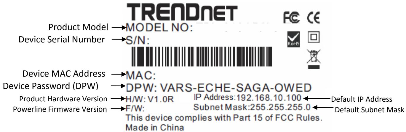
1.3 Device Label
The device label can be located on the back of the device where the power prong is found.
1.4 LEDs & Buttons
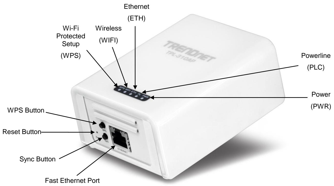
| LED | Color | Sequence | Definition |
| PWR (Power) | Green | Solid | Device powered On |
| N/A | Off | Device powered Off | |
| PL (Powerline)Note: LED color indicates the strength and quality of the powerline connection through the electrical system | Green | Solid | Powerline Connected (Connection Quality is Best) |
| Blinking | Syncing or Powerline Data Transmitting/Receiving (Connection Quality is Best) | ||
| Amber | Solid | Powerline Connected (Connection Quality is Better) | |
| Blinking | Powerline Data Transmitting/Receiving (Connection Quality is Better) | ||
| Red | Solid | Powerline Connected (Connection Quality is Good) | |
| Blinking | Powerline Data Transmitting/Receiving (Connection Quality is Good) | ||
| N/A | Off | Powerline is not synced or connected | |
| ETH(Ethernet Port) | Green | Solid | 10/20 Mbps, 100/200Mbps, or 1000/2000Mbps (Half/Full Duplex) Connected |
| Blinking | 10/20Mbps, 100/200Mbps, or 1000/2000Mbps (Half/Full Duplex) Data Transmitting/Receiving | ||
| N/A | Off | Port Disconnected/No Ethernet Link | |
| WIFI(Wireless) | Green | Blinking | Wireless is on or enabled / Wireless Data Transmission |
| N/A | Off | Wireless is off or disabled | |
| WPS(WiFi Protected Setup) | Green | Blinking | WPS is activated |
| N/A | Off | WPS is not activated or disabled |
*Note: The following factors may affect the powerline network's connection quality:
- Noise – Generated by appliances that are connected to your electrical system through power outlets that have high power consumption requirements. (e.g. Microwaves, ovens, blow dryer, iron, dishwasher, etc.) The quality of your household electrical wiring may also cause additional noise on your electrical system.
- Distance – Long lengths of electrical wiring through your electrical system between connected powerline adapters.
| Button | Action | Function |
| Sync | Push/Hold for 2 sec | Initiate Sync/Connection and generate random network name/key on first adapter (PWR LED will start blinking) |
| Match network name/key on secondary or additional adapter and connect to first adapter. (PWR LED will start blinking) | ||
| Note: The secondary or additional powerline adapter's Sync button must also be pushed within 2 minutes (120 sec) of pushing the Sync button of the first adapter in order to establish connectivity. | ||
| Push/Hold for 10 sec | Erases the network name/key (All LEDs will turn off and turn back on) | |
| WPS | Push/Hold for 3 sec | Activates Wi-Fi Protected Setup (WPS) |
| Reset | Push/Hold for 1 sec | Reset to Powerline factory defaults only (All LEDs will turn off and turn back on, PL LED will blink Amber)Note: Will reset to the factory default private network name “HomePlugAV”. This will not reset Wireless Access Point settings and the settings will remain intact. |
| Push/Hold for 5 sec | Reset to Wireless Access Point factory defaults only (All LEDs will turn off and turn back on)Note: This will not reset Powerline settings and the settings will remain intact. |
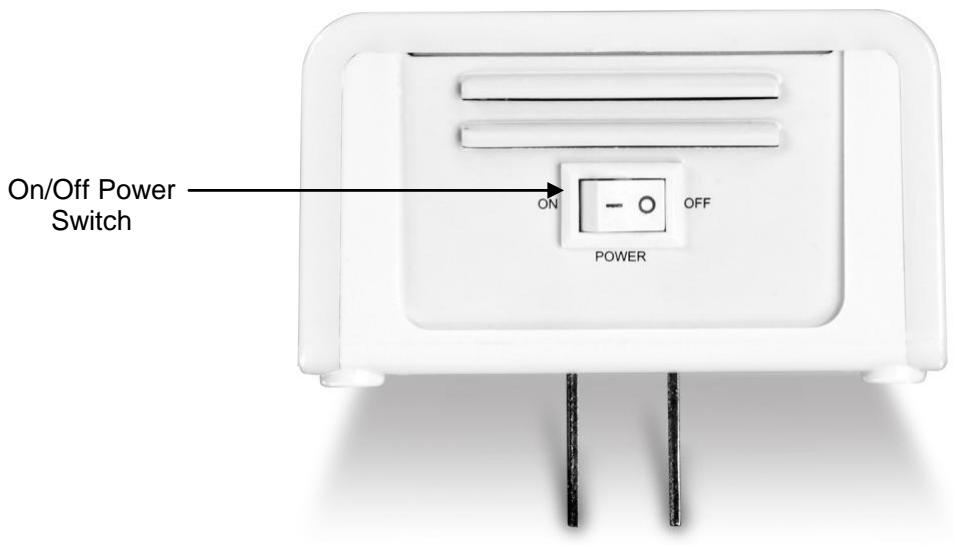
1.5 Top Panel
There On/Off Power switch is located on the top panel of the device which is used to power the device on or off.
1.6 Defaults Settings
| Wireless AP | Setting |
| IP Address / Subnet Mask | 192.168.10.100 / 255.255.255.0 |
| SSID | TRENDnet310 |
| SSID Broadcast | Enabled |
| Mode | Access Point (AP) |
| Channel | Auto |
| Channel Width | 20MHz |
| 802.11 Mode | 802.11b/g/n Mixed |
| Security | Disabled |
| Username / Password | admin / admin |
| Powerline | Setting |
| Network Name/Security Key | HomePlugAV |
When installing the TPL-310AP for the first time, it required for you to configure the device from a wired computer. Since the default IP address of the TPL-310AP is 192.168.10.100, please make sure to assign an IP address to the TPL-310AP that is NOT assigned to any other devices on your network. If your network IP address range is NOT 192.168.10.x, then the TPL-310AP IP address should be assigned with your network's IP address range (i.e. 192.168.1.x, 192.168.2.x, 192.168.0.x) This chapter covers the typical configuration of the TPL-310AP in Access Point (AP) mode using the Setup Wizard. If you are an experienced user, other web configuration settings can be referenced in Chapter 3. Once the initial setup is complete, Chapter 4 will cover creating a powerline network with one additional powerline adapter, or adding the TPL-310AP to existing powerline network.
- Plug the TPL-310AP into an available power outlet within reach of your computer's network cable.
- Connect a network cable from the TPL-310AP Wireless Access Point's network port (located at the bottom of the device) into the computer's network port.
- Move the power switch (located at the top of the device) to the "On" position.
- Assign a static IP address to your computer's network adapter to 192.168.10.10 and subnet mask 255.255.255.0.
Windows 7: Click on the Start Button, select Control Panel, click Network and Internet, click on Network and Sharing Center, and click Change Adapter Settings. Then, right-click the Local Area Connection icon and click Properties. Click Internet Protocol Version 4 (TCP/IPv4) and then click Properties. Select Use the following IP address, and manually enter the IP address settings.
Windows Vista: Click on the Start Button, select Control Panel, click Network and Internet, click on Network and Sharing Center, and click Manage Network Connections. Then, right-click the Local Area Connection icon and click Properties. Click Internet Protocol Version 4 (TCP/IPv4) and then click Properties. Select Use the following IP address, and manually enter the IP address settings.
Windows XP/2000: Click on the Start Button, select Control Panel, double-click the Network Connections icon, and then click Properties. Click Internet Protocol (TCP/IP) and then click Properties. Select Use the following IP address, and manually enter the IP address settings.
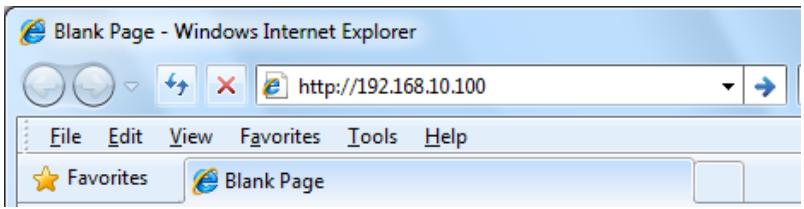
- Open your Web browser, and type http://192.168.10.100 in the Address bar, and then press Enter.
- Enter the User Name and Password and then click OK.
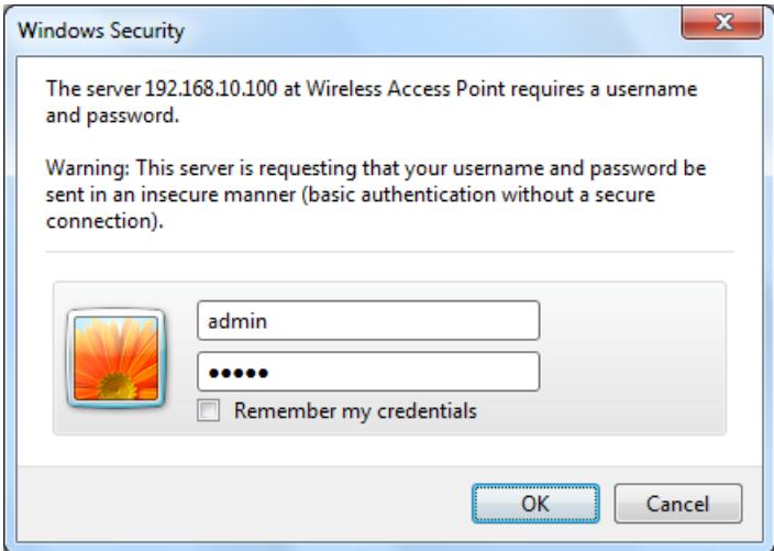
- In the menu in the left-hand panel, click on Setup Wizard.
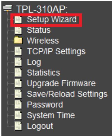
- In the Setup Wizard window, click Next
Setup Wizard
The setup wizard will guide you through configuring the wireless access point for the first time. Please follow the step-by-step Setup Wizard to complete the basic configuration for the wireless access point.
Welcome to the Setup Wizard.
The Setup Wizard will guide you through the steps below. To start the wizard, click Next.
- LAN Interface Settings
- Wireless LAN Settings
- Wireless Security Settings
Next>>
- Configure the LAN Interface Settings of the TPL-310AP. Click Next.
Step 1: LAN Interface Settings
This page is used to configure the IP address parameters of the wireless access point for the local area network, which connects to the Ethernet port of your wireless access point. Please make sure that the IP address assigned to the wireless access point is available and is not being used by any other device connected to the local area network. When completed, click Next.
| IP Address: | 192.168.10.100 |
| Subnet Mask: | 255.255.255.0 |
| DHCP: | Disabled ▼ |
Cancel
<<Back
Next>>
IP Address: The assigned IP address should match the network IP address range of your network. This IP address should not be used by any other devices on your network.
Subnet Mask: The assigned Subnet Mask should match the network Subnet Mask of your network. In most cases, the default Subnet Mask setting (255.255.255.0) should be fine.
DHCP: Setting DHCP to Client will set your device to obtain an IP address automatically from your DHCP server (router). If Disabled, you will need to manually configure the IP address settings.
Note: It is recommended to manually configure the LAN Interface Settings (IP Address and Subnet Mask) in case you need access the device in the future. Please write down the IP address settings assigned for future reference.
- Configure the Wireless LAN Settings. Then click Next.
Step 2: Wireless LAN Settings
This page is used to configure the wireless access point parameters for wireless LAN clients to discover and establish wireless network connectivity. When completed, click Next.
| Band: | 2.4 GHz (B+G+N) |
| Mode: | AP |
| Network Type: | Infrastructure |
| SSID: | TRENDnet310 |
| Channel Width: | 20MHz |
| ControlSideband: | Upper |
| Channel Number: | Auto |
| Enable Mac Clone (Single Ethernet Client) | |
Cancel
<<Back
Next>>
Band: In most cases, the default setting (2.4GHz (B+G+N)) should be fine.
Mode: In most cases, the default setting AP (Access Point) should be fine.
Network Type: This setting does not apply to (AP) mode, only in (AP Client) mode. Continue to the next setting.
SSID: The SSID is the network name of your wireless network (The name wireless clients will discover, when scanning for wireless networks). It is recommended to assign a unique SSID (Network Name) and to not assign anything that would be personally identifying like “Smith Family Network” however, an SSID easily identifiable when searching for available wireless networks. Manually enter the name of your wireless network.
Channel Width: In most cases, the default setting (20MHz) should be fine.
Channel Number: This setting is only configurable when setting the Channel Width to 40MHz. In most cases, the default setting (Auto) should be fine.
Enable MAC Clone (Single Ethernet Client): This setting does not apply to (AP) mode, only in (AP Client) mode.
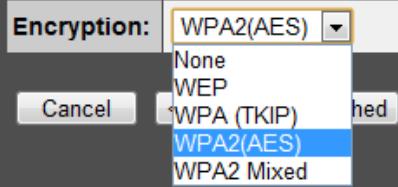
- Configure the Wireless Security Settings. Click the drop-down menu Encryption: and select WPA2(AES).
Note: To protect your network from unauthorized wireless access, it is strongly recommended to enable wireless security. It is highly recommended to use WPA2 if all of your wireless devices also support WPA2, since it is the highest security protocol supported currently. Once wireless security is enabled on the TPL-310AP, each wireless computer or device must be configured to use the same protocol (WEP, WPA, WPA2) and configured with the same security key. Make sure your wireless devices support the security protocol configured on the TPL-310AP. If you are unsure of the security protocols supported, please refer the manuals for your wireless devices or contact the manufacturer to find out these details. The example demonstrates how to configure the TPL-310AP for WPA2.
Step 3: Wireless Security Settings
This page allows you to configure the wireless access point security settings in order to prevent unauthorized access to the wireless network and local area network. When completed, click Finished.
- Click the drop-down menu Pre-Shared Key Format: and select Passphrase.
Step 3: Wireless Security Settings
This page allows you to configure the wireless access point security settings in order to prevent unauthorized access to the wireless network and local area network. When completed, click Finished.

3.3 Status
Access Point Status This page shows the current status and some basic settings of the device. System| Uptime | 2day:3h:46m:35s |
| Firmware Version | v1.61 |
| Build Time | Fri Aug 27 03:03:12 EDT 2010 |
| Mode | AP |
| Band | 2.4 GHz (B+G+N) |
| SSID | TRENDnet310 |
| Channel Number | 6 |
| Encryption | WPA2 |
| BSSID | 00:08:54:9a:a2:65 |
| Associated Clients | 0 |
| Attain IP Protocol | Fixed IP |
| IP Address | 192.168.10.100 |
| Subnet Mask | 255.255.255.0 |
| Default Gateway | 0.0.0.0 |
| MAC Address | 00:08:54:9a:a2: |
| Items | Information |
| Uptime | The period that you turn the device on. |
| Firmware version | The current firmware version of the device. |
| Build Time | The build time of the device originally. |
| Mode | Displays the current Access Point mode. |
| Band | The band that the wireless AP operating. |
| SSID | The name of this wireless network. |
| Channel Number | The channel that the wireless network using. |
| Encryption | The security encryption type that the wireless network using. |
| BSSID | The Basic Service Set Identity of this AP (This parameter is the same as the MAC address of LAN port) |
| Associated Clients | The number of members who is currently connected with this AP. |
| Attain IP Protocol | Displays whether the IP address is set statically (Fixed IP) or obtained automatically (DHCP). |
| IP Address | The current IP address of this AP. |
| Subnet Mask | The current subnet mask of this AP. |
| Default Gateway | The current default gateway of this AP. |
| MAC Address | The current MAC address of this AP. |
3.4 Wireless
3.4.1 Apply/Reset Changes
Clicking the Apply Changes button will take you to the confirmation screen that will prompt you to "Reboot Now" or "Reboot Later"Settings Saved
Your changes have been saved. The router must be rebooted for the changes to take effect. You can reboot now, or you can continue to make other changes and reboot later. Reboot Now Reboot Later Clicking “Reboot Now” will apply the changes and reboot the device. Clicking “Reboot Later” will store but not apply the current configuration changes and allow you to make more configuration changes before applying all the changes and reboot the device. Clicking the Reset button will discard all of the current changes in the current page.3.4.2 Basic Settings
This page is used to configure the wireless point parameters for wireless LAN clients to discover and establish wireless connectivity. This page is also used to set the wireless access point mode.Wireless Basic Settings
This page is used to configure the wireless access point parameters for wireless LAN clients to discover and establish wireless network connectivity. Disable Wireless LAN Interface| Band: | 2.4 GHz (B+G+N) | |
| Mode: | AP | Multiple SSID |
| Network Type: | Infrastructure | Client Mode only |
| SSID: | TRENDnet310 | |
| Channel Width: | 20MHz | |
| Control Sideband: | Upper | 40MHz Channel Width and assigned Channel Number only |
| Channel Number: | Auto | |
| Broadcast SSID: | Enabled | |
| WMM: | Enabled | |
| Data Rate: | Auto | |
| Associated Clients: | Show Active Clients | |
| Clone MAC Address (Client Mode only) | ||
| Universal Repeater Mode (AP, Client, and AP+WDS Modes only) | ||
| Enter the SSID to Repeat: | ||
| Apply Changes Reset | ||
| Items | Information |
| Disable Wireless LAN Interface | Mark the checkbox to disable wireless. |
| Band | To select a band for this device to match 802.11b, 802.11g, 802.11n, 802.11b/g, 802.11g/n or 802.11b/g/n. optional parameters:2.4GHz(B),2.4GHz(G),2.4GHz(N),2.4GHz(B+G),2.4GHz(G+N),2.4GHz(B+G+N) |
| Mode | Configure this device as AP, Client, WDS or AP+WDS, AP+MESH,MESH. If you set this device as AP or AP+WDS mode, the Multiple SSID button is available for you to set up four SSID for this wireless network. Click on this button to do more configurations.Description of ModesAP (Access Point): Allows wireless clients or devices to establish connectivity.Client: Allows the device to connect to another wireless access point and establish connectivity through the network port. Also known as wireless adapter mode.WDS (Wireless Distribution System): Allows the device to establish a WDS wireless bridge to other WDS supported wireless access points.AP+WDS (Access Point + Wireless Distribution System): Allows wireless clients or devices to establish connectivity and allows the device to establish a WDS wireless bridge to other WDS supported wireless access points simultaneously.Mesh: Allows the device to establish a wireless mesh network with other mesh supported wireless access points.AP+Mesh (Access Point + Mesh): Allows wireless clients or devices to establish connectivity and allows the device to establish a wireless mesh network with other mesh supported wireless access points simultaneously. |
| Network Type | When you configure this device in AP Client mode, this drop-down list allows users to change the network type into infrastructure mode or ad-hoc mode.Ad-Hoc mode: connects two computers directly without the use of a router or AP. It is also known as a peer-to-peer network.Infrastructure Mode: the wireless network contains at least one wireless client and one wireless AP or router. This client connects to Internet or intranet by communicating with this wireless AP. |
| SSID | Service set identifier (SSID) for the name of the wireless network. |
| Channel Width | Select to use 20MHz or 40MHz as the wireless channel frequency. |
| Control Sideband | If you have selected the channel width of 40MHz for this AP, you can control this AP to use the frequency for a deflection of “Upper” or “Lower.” |
| Channel Number | Select a channel for the wireless network of this device. |
| Broadcast SSID | If you enable "Broadcast SSID", every wireless station located within the coverage of this wireless AP can discover this wireless AP easily. If you are building a public wireless network, enabling this feature is recommended. Disabling "Broadcast SSID" can provide better security. |
| WMM | This will enhance the data transfer performance of multimedia contents when they're being transferred over wireless network. WMM is not available in 11n mode. |
| Data Rate | The transmission rate of data packets of this wireless AP. The wireless AP will use the highest possible selected transmission rate to transmit the data packets if set to Auto. |
| Associated Clients | Click "Show Active Clients" button, then an "Active Wireless Client Table" pops up. You can see the status of all active wireless stations that are connecting to the access point. |
| Enable MAC clone | Mark the checkbox to clone the MAC address of the device. This function is only available when you set this AP as Client mode. You can also manually set the MAC address in LAN setting. |
| Enable Universal Repeater Mode | Mark this checkbox to enable Universal Repeater Mode which allows the TPL-310AP to repeat the signal of another wireless access point. Available in AP, Client, or AP+WDS modes only. |
| SSID of Extended Interface | When enabling the Universal Repeater Mode, specify an SSID for the extended interface. |
3.4.3 Multiple SSID
This is the window that pops up after clicking the Multiple SSID button. Select one of the AP, and then click the button "Show", "Active Wireless Client Table – AP1" windows pops up.| Multiple SSIDs | |||||||
| This page is used to enable and configure multiple SSIDs for wireless LAN clients to discover and establish connectivity. | |||||||
| No. | Enable | Band | SSID | Data Rate | Broadcast SSID | WMM | Active Client List |
| AP1 | 2.4 GHz (B+G+N) | Auto | Enabled | Show | |||
| AP2 | 2.4 GHz (B+G+N) | Auto | Enabled | Show | |||
| AP3 | 2.4 GHz (B+G+N) | Auto | Enabled | Show | |||
| AP4 | 2.4 GHz (B+G+N) | Auto | Enabled | Show | |||
3.4.4 Active Wireless Client Table
This is the window that pops up after clicking the Show Active Clients button. This will display information on wireless currently connected to each SSID including the primary.Active Wireless Client Table
This table shows the MAC address, transmission, reception packet counters and encrypted status for each associated wireless client.| MAC Address | Mode | Tx Packet | Rx Packet | Tx Rate (Mbps) | Power Saving | Expired Time (s) |
| None | --- | --- | --- | --- | --- | --- |
3.4.5 Advanced Settings
You can set advanced wireless LAN parameters of this AP. Note: The settings on this page are intended for more advanced users who have sufficient knowledge of wireless LAN technology. Please do not modify these settings unless you are well aware of the effects on the wireless access point functionality and performance as a result of these changes. Wireless Advanced Settings| The settings on this page are intended for more advanced users who have sufficient knowledge of wireless LAN technology. Please do not modify these settings unless you are well aware of the effects on the wireless access point functionality and performance as a result of these changes. |
| Fragment Threshold: | 2346 (256-2346) |
| RTS Threshold: | 2347 (0-2347) |
| Beacon Interval: | 100 (20-1024 ms) |
| Preamble Type: | ○ Long Preamble ○ Short Preamble |
| IAPP: | ○ Enabled ○ Disabled |
| Protection: | ○ Enabled ○ Disabled |
| Aggregation: | ○ Enabled ○ Disabled |
| Short GI: | ○ Enabled ○ Disabled |
| WLAN Partition: | ○ Enabled ○ Disabled |
| RF Output Power: | ○ 100% ○ 70% ○ 50% ○ 35% ○ 15% |
| Items | Information |
| Fragment Threshold | This value should remain at its default setting of 2346. If you experience a high packet error rate, you may slightly increase your fragmentation threshold within the value range of 256 to 2346. Setting the fragmentation threshold too low may result in poor performance. |
| RTS Threshold | Request To Send threshold. This value should remain at its default setting of 2347. If you encounter inconsistent data flow, only minor modifications to the value range between 0 and 2347 are recommended. |
| Beacon Interval | Beacons are packets sent by an access point to synchronize awireless network. Specify a beacon interval value. Default (100ms) is recommended. |
| Preamble Type | The length of CRC blocks in the frames during the wireless communication. |
| IAPP | To enables multiple AP to communicate and pass information regarding the location of associated Stations. |
| Protection | Some 802.11g wireless adapters support 802.11g protections, which allows the adapter search for 802.11b/g singles only. Select “Enabled” to support protection or select “Disabled” to disable this function. |
| Aggregation | To aggregate lots of packets into a big one before transmitting packets. This can reduce control packet overhead. |
| Short GI | Indicates that the 802.11g network is using a short slot time because there are no legacy (802.11b) stations present |
| RF Output Power | Select the signal strength for the wireless network. |
3.4.6 Security
To protect your network from any unauthorized access, it is recommended to enable wireless security. Once wireless security is enabled on the Wireless Access Point, each wireless computer or device must be configured with the same encryption and key. If you select WPA or WPA2 sure your wireless adapters support WPA or WPA2. If your wireless adapters do not support WPA or WPA2, then select WEP. Please select Disable, WEP, WPA, WPA2, and WPA-Mixed in the drop list. If you select none, any data will be transmitted without encryption and any station can access the AP. Note: If you have the Multiple SSID feature enabled (Section 3.4.3), then those SSIDs will be available in the drop-down menu “Select SSID” and you can assign different security types to different SSIDs. Note: This section applies to both AP and client modes. For configuring security on WDS and Mesh, please refer to the their sections in this User Guide.Step 3: Wireless Security Settings
This page allows you to configure the wireless access point security settings in order to prevent unauthorized access to the wireless network and local area network. When completed, click Finished.   \* Please click on the Apply Changes button or the Reset button to save/reset the configuration.| Items | Information |
| Encryption | Select a security encryption mode for this AP. |
| 802.1xAuthentication | Check this option if to use an external 802.1x RADIUS server for authentication. |
| Authentication | There provide three options for selecting: Open System, Shared Key, Auto |
| Key Length | Select 64-bit or 128-bit as the key encryption length. |
| Key Format | Select ASCII or Hex (0-9, A-F) to setup the key value. |
| Encryption Key | Enter the key according to the key format you select. |
WPA/WPA2 Security
| Select SSID: Root AP - TRENDnet310 Apply Changes Reset | |
| Encryption: | WPA |
| Authentication Mode: | ○ Enterprise (RADIUS) ● Personal (Pre-Shared Key) |
| WPA Cipher Suite: | ✓ TKIP □ AES |
| Pre-Shared Key Format: | Passphrase |
| Pre-Shared Key: | ............ |
| Select SSID: Root AP - TRENDnet310 Apply Changes Reset | |
| Encryption: | WPA |
| Authentication Mode: | ○ Enterprise (RADIUS) ○ Personal (Pre-Shared Key) |
| WPA Cipher Suite: | ✓ TKIP □ AES |
| RADIUS Server IP Address: | |
| RADIUS Server Port: | 1812 |
| RADIUS Server Password: | |
| Items | Information |
| Authentication Mode | There are two items, “Enterprise (RADIUS)” and “Personal (Pre-Shared Key)”. You can select the mode by clicking the item. |
| WPA Cipher Suite | Select the WPA Cipher Suite to be TKIP or AES. |
| Pre-Shared Key Format | To decide the format, select Passphrase or Hex in the drop down menu. |
| Pre-Shared Key | Enter the Pre-shared Key according to the pre-shared key format you select. This is the shared secret between AP and STA. This field must be filled with character. longer than 8 and less than 64 lengths.(The default value is 1234567890ab) |
WPA Mixed
| Select SSID: Root AP - TRENDnet310 Apply Changes Reset | |
| Encryption: | WPA-Mixed |
| Authentication Mode: | ○ Enterprise (RADIUS) ○ Personal (Pre-Shared Key) |
| WPA Cipher Suite: | ☑ TKIP ☐ AES |
| WPA2 Cipher Suite: | ☐ TKIP ☑ AES |
| Pre-Shared Key Format: | Passphrase |
| Pre-Shared Key: | ............ |
| Select SSID: Root AP - TRENDnet310 ▼ Apply Changes Reset | |
| Encryption: | WPA-Mixed ▼ |
| Authentication Mode: | ◎ Enterprise (RADIUS) ○ Personal (Pre-Shared Key) |
| WPA Cipher Suite: | ☑ TKIP ☐ AES |
| WPA2 Cipher Suite: | ☐ TKIP ☑ AES |
| RADIUS Server IP Address: | |
| RADIUS Server Port: | 1812 |
| RADIUS Server Password: | |
| Items | Information |
| Authentication Mode | There are two items, “Enterprise (WPA-Radius)” and “Personal (Pre-Shared Key)”. You can select the mode by clicking the item. |
| WPA / WPA2 Cipher Suite | Select the WPA/WPA2 Cipher Suite to be TKIP or AES. |
| Pre-Shared Key Format | To decide the format, select Passphrase or Hex inthe drop list. |
| Pre-Shared Key | Enter the Pre-shared Key according to the pre-shared key format you select. This field must be filled with character longer than 8 and less than 64 lengths. (The default value is 1234567890ab) |
3.4.7 Access Control
To restrict the clients of Access authentication of wireless clients by MAC address, set up the access list in this page. If the Wireless Access Control Mode is set to "Allow Listed", only the wireless LAN clients whose MAC addresses are listed in the Current Access Control List will be able to connect to the wireless access point and all other clients not listed will be denied access. If the mode is set to "Deny Listed", the wireless LAN clients whose MAC addresses are listed in the Current Access Control List will not be able to connect to the wireless access point and all other clients will be allowed access. This feature is only available when using AP, AP+WDS, or AP+Mesh modes located under Wireless > Basic Clicking "Delete Selected" will delete the checked entries in the list. Clicking "Delete All" will delete all of the entries listed. | Items | Information |
| Wireless Access Control Mode | Click on the drop list to choose the access control mode. You may select “Allow listed” to allow those allowed MAC addresses or select “Deny Listed” to ban those MAC addresses from accessing to this device or select “Disable”. |
| MAC Address & Comment | Fill in the MAC address that you wish to control, and give a definition to it.(MAC Address Format: xxxxxxxxxxxx) |
| Current Access Control list | Lists the MAC Access Control Settings you have added before. Click on the list to change configuration. To Delete the station on the list, mark the check box in the select item and click the “Delete Selected”. If you want to delete allstations on the list, click “Delete All” to remove all of them. |
3.4.8 WDS Settings
Wireless Distribution System (WDS) mode uses wireless media to connect to other wireless access points. Another term for this feature is wireless point to point or point to multi-point bridging. Wireless access points using WDS mode must be configured to use the same channel number, wireless security type, and wireless security key. Add other WDS enabled wireless access points using their device MAC addresses. This feature is only available when using WDS, AP+WDS, Mesh, or AP+Mesh modes located under Wireless > Basic Settings. To use WDS, you will require at least 2 or more wireless access points that support WDS. Note: WDS is not a wireless standard and connectivity may or may not be established between different wireless access point devices that support this feature. It is recommended to use the same device model when using this feature. | Items | Information |
| MAC Address & Comment | Fill in the MAC address that you wish to control, and give a definition to it.(MAC Address Format: xxxxxxxxxxxxx) |
| Data Rate | The transmit limitation of data packets of this wireless AP. The wireless AP will use the highest possible selected transmission rate to transmit the data packets. |
| Current WDS AP List | Lists the WDS Settings you have added before. Click on the list to change configuration. To Delete the station on the list, mark the check box in the select item and click the “Delete Selected”. If you want to delete all stations on the list, click “Delete All” to remove all of them. |
3.4.9 Mesh Settings
Wireless Mesh mode uses wireless media to connect to other wireless access points. Another term for this feature is wireless point to point or point to multi-point bridging. Unlike WDS mode, wireless mesh mode can provide redundancy and dynamic path selection through multiple Mesh enabled wireless access points. Wireless access points using wireless mesh mode must be configured to use the same channel number, Mesh ID, wireless security type, and wireless security key. This feature is only available when using Mesh or AP+Mesh modes located under Wireless > Basic Settings. To use Mesh, you will require at least 2 or more wireless access points that support Mesh. It is ideal to have at least 3 wireless access points. | Items | Information |
| Mesh ID | Enter the Mesh ID used for your wireless mesh network. The ID should also be entered on any other wireless access points that should belong to your wireless mesh network. |
| Encryption | To enable security for Mesh mode, select the encryption mode WPA2(AES). |
| Pre-Shared Key Format | To decide the format, select Passphrase or Hex in the drop down menu. |
| Pre-Shared Key | Enter the Pre-shared Key according to the pre-shared key format you select. This field must be filled with character longer than 8 and less than 64 lengths. The key should also be entered on any other wireless access points that belong to your wireless mesh network. |
3.4.10 Site Survey
This page displays basic information about available wireless networks. When the TPL-310AP is configured in Client mode located under Wireless > Basic Settings, this page will allow you to scan and establish wireless connectivity to available wireless networks (access points or wireless routers). Wireless Site Survey This page allows you to scan and provide basic information about available wireless networks. When using Client mode located under Wireless > Basic Settings, this page will allow you to scan and establish wireless connectivity to available wireless networks.| SSID | BSSID | Channel | Type | Encrypt | Signal | Select |
| 00:c0:02:1a:af:c1 | 8 (B+G) | AP | WPA-PSK/WPA2-PSK | 52 | ◎ | |
| 00:14:d1:62:0d:1d | 10 (B+G+N) | AP | no | 46 | ◎ | |
| 00:0d:56:01:23:16 | 1 (B+G+N) | AP | WPA2-PSK | 44 | ◎ | |
| 00:14:d1:aa:cf:68 | 11 (B+G+N) | AP | WPA2-PSK | 42 | ◎ | |
| 00:14:d1:aa:50:88 | 11 (B+G+N) | AP | no | 40 | ◎ | |
| 00:14:d1:c3:bd:dd | 3 (B+G+N) | AP | WPA2-PSK | 38 | ◎ | |
| 00:c0:02:e7:d0:f0 | 1 (B+G) | AP | WEP | 36 | ◎ | |
| 00:e0:4c:81:86:82 | 11 (B+G+N) | AP | no | 34 | ◎ | |
| 00:c0:02:90:f4:62 | 1 (B+G) | AP | WEP | 32 | ◎ | |
| 00:0e:8e:7d:2e:54 | 5 (B+G) | AP | WPA-PSK | 32 | ◎ | |
| 00:14:d1:cb:b2:58 | 9 (B+G+N) | AP | WPA2-PSK | 32 | ◎ | |
| 00:14:d1:cb:67:b8 | 6 (B+G+N) | AP | WPA2-PSK | 30 | ◎ | |
| 00:14:d1:c3:bf:eb | 1 (B+G+N) | AP | WPA-PSK | 30 | ◎ | |
| 00:14:d1:c0:64:19 | 2 (B+G) | AP | WPA-PSK | 30 | ◎ | |
| 00:14:d1:c6:c2:ef | 1 (B+G+N) | AP | WPA-PSK | 28 | ◎ |
3.4.11 WPS
This page allows you to configure the settings for Wi-Fi Protected Setup (WPS). Using this feature allows you to connect WPS enabled wireless LAN clients to the wireless access point quickly and easily with one of the following methods: Virtual Push Button (PBC), Hardware Push Button (Located on physical device), or PIN number. This feature is only available when the Broadcast SSID is Enabled and using AP, AP+WDS, or AP+Mesh modes located under Wireless > Basic Settings. WPS can also be used in Client mode to establish connectivity to another wireless access point or wireless router. | Items | Information |
| WPS Status | You cannot manually select the items here. The WPS Status will change from “UnConfigured” to “Configured” after you enable WPS function and setup a wireless security key for this device. |
| Self-PIN Number | If you use this device as a client, you can use this code when trying to connect this device to other AP by using the PIN method. |
| Push Button Configuration | Push Button Communication (PBC) method use a simple action of pushing a button on both the AP and the new STA to reach the function of easy setup WPS connection. You can simply click the Start PBC button in this GUI page. After click on the button, please run the client’s WPS and push the PBC button within 2 minutes. |
| Client PIN Number | Personal Identification Number (PIN) method. Users have to fill in the PIN code of enrollee device and click on the Start PIN button to make communication with other AP. After click on the button, please run the client’s WPS and push the PIN button within 2 minutes. |
3.4.12 Schedule
This page allows you to setup a schedule when the wireless functionality is enabled. The wireless functionality will be disabled for any other days and time not configured within the schedule on this page. Please remember to configure the device System Time first (Section 3.11), before creating the wireless schedule. | Items | Information |
| Enable Wireless Schedule | Checking this box enables the wireless schedule function. |
| Days | Everyday: Checking this option will select all days.Sun, Mon, Tue, Wed, Thu, Fri, Sat: Check the days you want the wireless schedule to be active. |
| Time | 24 Hours: Checking this option will select all hours of the days you have selected.From: Click the drop-down menus to set the time the wireless functionality will be turned on. (The options are in 5 minutes increments)To: Click the drop-down menus to set the time the wireless functionality will be turned off. (The options are in 5 minutes increments) |
3.5 TCP/IP Settings
This page is used to configure the IP address parameters of the wireless access point for the local area network, which connects to the Ethernet port of your wireless access point. Please make sure that the IP address assigned to the wireless access point is available and is not being used by any other device connected to the local area network.| LAN Interface Setup | ||
| This page is used to configure the IP address parameters of the wireless access point for the local area network, which connects to the Ethernet port of your wireless access point. Please make sure that the IP address assigned to the wireless access point is available and is not being used by any other device connected to the local area network. | ||
| IP Address: | 192.168.10.100 | |
| Subnet Mask: | 255.255.255.0 | |
| Default Gateway: | 0.0.0.0 | |
| DHCP: | Disabled ▼ | |
| 802.1d Spanning Tree: | Disabled ▼ | |
| Clone MAC Address: | 000000000000 | Wireless Client Mode only and enable Clone MAC Address under Wireless > Basic Settings |
| Apply Changes Reset | ||
| Items | Information |
| IP Address | The IP of your AP LAN port (default 192.168.10.100). |
| Subnet Mask | Subnet Mask of you LAN (default 255.255.255.0). All devices on the network must have the same subnet mask to communicate on the network. |
| Default Gateway | Enter the IP Address of the AP in your network. |
| DHCP | DHCP stands for Dynamic Host Configuration Protocol. It is a protocol for assigning dynamic IP addresses “automatically”. In this device, manual setting up your client IP is necessary when you want to use the AP as your client’s default gateway. |
| 802.1d Spanning Tree (STP) | Enabled:Suitable for office environment, for example, there are over 3 Ethernet switches or Routers or APs are being used at the same time. Because STP (Spanning Tree Protocol) needs 2~49 seconds to take effect.Disabled:Suitable for ordinary application when there are less than 3 Ethernet switches or Routers or APs working the same time, for example, ordinary home. |
| Clone MAC Address | Applies to Client mode only. Enter the MAC address you would like to clone to the TPL-310AP. This will be the MAC address that will appear on the access point or wireless router you are connected to when in Client mode. If there is no value here, then the TPL-310AP MAC address will be used unless Enable MAC Clone is check under Wireless > Basic Settings. Section 3.4.2 (MAC Address Format: xxxxxxxxxxxx) |
3.6 Log
This page is used to display the device internal system log or send system logs to a remote log server (Syslog). | Items | Information |
| Enable Log | Checking this option enables the in logging function of the TPL-310AP. If enable, the logging information will display in the blank white box in the page.Types of Loggingsystem all – Logs all system and debug information.wireless – Logs only information related to the wireless functionality of the device.11s – Logs only information about wireless mesh. (Applies only when using Mesh & AP+Mesh modes.) |
| Enable Remote Log | Sends or forwards logging information to an external log server (Syslog server).Log Server IP Address: Enter the IP address of the external log server (Syslog server). |
3.7 Statistics
This page displays the number of packets transmitted and received on the wireless and wired Ethernet interfaces for monitoring purposes. To display the latest information, click the Refresh button.Statistics
This page displays the number of packets transmitted and received on the wireless and wired Ethernet interfaces for monitoring purposes.| Wireless LAN | Sent Packets | 29629 |
| Received Packets | 4767729 | |
| Ethernet LAN | Sent Packets | 3645 |
| Received Packets | 14361 | |
| Refresh | ||
3.8 Upgrade Firmware
This page allows you to upload firmware to the device. Firmware updates may provide bug fixes and/or enhancements to the functionality of the device and if available, can be downloaded from the downloads section on TRENDnet website (http://www.trendnet.com) Please do not power off the device until the firmware upload procedure is completed as this may crash the system or damage the device. To upgrade the firmware, please click on the Browse... button, navigate to the extracted firmware file location on your computer and then click the Upload button to start the firmware upgrade.Upgrade Firmware
This page allows you to upload firmware to the device. Please do not power off the device until the firmware upload procedure is completed as this may crash the system or damage the device. Select File: Browse. Upload Reset3.9 Save/Reload Settings
This page allows you to save your current wireless access point configuration to a file and restore the wireless access point settings from a previously saved configuration file on this device. This page also allows you to reset the wireless AP configuration to factory default settings. (Does not affect powerline settings)Save/Reload Settings
This page allows you to save your current wireless access point configuration to a file and restore the wireless access point settings from a previously saved configuration file on this device.| Save Settings to File: | Save... | ||
| Load Settings from File: | Browse... | Upload | |
| Reset Settings to Default: | Reset | ||
| Items | Information |
| Save Settings to File | Click on the Save... button to save the current wireless AP configuration to file to a location on your computer. |
| Load Settings from File | Click Browse... to select the file that you want to restore, and then click Upload to start the restore process. |
| Reset Settings to Default | Click Reset to reset the wireless AP configuration to factory default settings. |
3.10 Password
This page allows you to configure the administrative user account for managing the wireless access point and access to the web graphical user interface. Leaving the User Name and Password fields blank or empty will disable the user account protection. To change the administrator user name and password, enter the User Name, New Password, and confirm the password. Click the Apply Changes button to save the changes. 3.11 System Time
This page allows you to set the device system time and also displays the current device time. Click Re-fresh to update the device time displayed. To set the device time, you can manually enter edit the time displayed or you can click on Copy Computer Time to copy your computer's current time settings. Click Apply Change to save the changes. Note: This section should be configured first, before configuring the wireless schedule (Section 3.4.12) 3.12 Logout
This page is used to logout of the wireless access point web management interface.  At factory default powerline settings, the TPL-310AP 200Mbps Powerline AV Wireless N Access Point (or other TRENDnet HomePlug® AV powerline adapter models TPL-303E, TPL-304E, TPL-305E, TPL-401E) can be installed into any room in your home or small office with a wall power outlet, without the need for additional software or configuration. Assuming the TRENDnet HomePlug® AV powerline adapters are at factory default settings, to create a powerline network using the TPL-310AP and another TRENDnet HomePlug® AV powerline adapter, simply plug one of the powerline adapters into a wall power outlet in one room and plug the other powerline adapter into an available wall power outlet in another room to establish connectivity between the two rooms. In order to share Internet connectivity through your powerline adapters, it is ideal to install at least one powerline adapter in the room where your modem and router are located and connect the powerline adapter to one of your router's LAN ports via Ethernet network cable. Any additional powerline adapters that are installed and connected in other rooms will then share Internet connectivity through your router. Once the powerline adapters are connected to each other through the electrical system, any additional devices such as computers or network appliances (e.g. Game Console, Blu-ray player, IP Set Top Box, network enabled TV, etc.) connected to any of your powerline adapters via Ethernet can then communicate to each other as well as share Internet connectivity through your router. flowchart
graph TD
    A["Media Server"] --> B["Game Console"]
    B --> C["Wireless N USB Adapter (TEW-624UB)"]
    C --> D["Wireless N 4-Port Media Bridge (TEW-640MB)"]
    D --> E["Powerline AV Adapter (TPL-303E)"]
    E --> F["Router"]
    F --> G["TRENONET"]
    style A fill:#f9f,stroke:#333
    style B fill:#ccf,stroke:#333
    style C fill:#cfc,stroke:#333
    style D fill:#fcc,stroke:#333
    style E fill:#cff,stroke:#333
    style F fill:#ffc,stroke:#333
    style G fill:#fcc,stroke:#333
4.1 Create a powerline network and extend you wireless network
The following procedure describes how to create a basic powerline network between the TPL-310AP and an additional TRENDnet powerline adapter model TPL-303E (or TPL-304E, TPL-305E, TPL-401E) and share Internet connection through a router to a computer or network appliance in another room. The procedure assumes the following: - You have one additional TRENDnet HomePlug® AV powerline adapter (models TPL-303E, TPL-304E, TPL-305E, TPL-401E) and the powerline settings are set to factory defaults. If you have an existing powerline network (2 or 3 other TRENDnet powerlines adapters already plugged in and connected) and you are adding the TPL-310AP, please refer to section 4.5. - The TPL-310AP has already been initially configured in (AP) Access Point mode to allow wireless computers or devices to wirelessly connect covered in Chapter 2. - Your router is already installed and configured for Internet connectivity. flowchart
graph TD
    A["Modem | Router"] --> B["Internet"]
    B --> C["HomePlug AV Ethernet Bridge"]
    C --> D["Powerline"]
    D --> E["PE827-AP"]
    E --> F["Computer"]
    E --> G["Laptop"]
    E --> H["Desktop"]
4.2 Securing your Powerline Network
The TPL-310AP 200Mbps Powerline AV Wireless N Access Point has a default powerline network name/security key assignment of “HomePlugAV”. When connecting TRENDnet HomePlug® AV powerline adapters, the adapters will be assigned the default network/security key which allows adapters to establish connectivity through your home or small office’s electrical system without the need for additional software or configuration. For added security, the default network name/security key can be modified using the TPL-310AP Sync button covered in the section 3.3 or through the use of the Powerline Configuration Utility in Chapter 5. Note: The default network name/security key assigned to the TPL-310AP is “HomePlugAV”. All powerline adapters in the same powerline network must have the same network name/security key in order to establish connectivity. If the network name/security keys are not the same for all powerline adapters on the same powerline network, the adapter will NOT establish connectivity. TRENDnet Powerline AV models TPL-303E, TPL-304E, TPL-305E, TPL-310AP, and TPL-401E all have the same default network name/security key assignment of “HomePlugAV”.4.3 Changing the Network Name/Security Key using the Sync Button
The procedure describes how to create a change the network name/security key between the TPL-310AP and an additional TRENDnet HomePlug® AV powerline adapter (models TPL-303E, TPL-304E, TPL-305E, TPL-401E). This procedure can also be used to establish connectivity between two powerline adapters that are currently disconnected and change the default network name/security key simultaneously. The example below demonstrates how to accomplish using the TPL-310AP and the TPL-303E, however, this procedure also applies to other TRENDnet HomePlug® AV powerline adapters. flowchart
graph LR
    A["Computer"] --> B["TPL-310AP"]
    B --> C["TPL-303E"]
    C --> D["Laptop"]
    B -.->|Electrical Wiring (Powerline Network)| C
4.4 Adding the Powerline Adapter to an Existing Powerline Network
The procedure describes how to add the TPL-310AP 200Mbps Powerline AV Wireless N Access Point to an existing powerline network. The example below demonstrates how to accomplish using the TPL-310AP and 2 additional TPL-303E powerline adapters, however, this procedure also applies to other TRENDnet HomePlug® AV powerline adapters. flowchart
graph TD
    A["Computer"] --> B["TPL-303E"]
    C["Computer"] --> D["TPL-303E"]
    E["Computer"] --> F["TPL-310AP"]
    G["Computer"] --> H["TPL-310AP"]
    I["Computer"] --> J["TPL-310AP"]
    K["Powerline Network"] -.-> L["Electrical Wiring (Powerline Network)"]
    style A fill:#f9f,stroke:#333
    style C fill:#f9f,stroke:#333
    style E fill:#f9f,stroke:#333
    style G fill:#f9f,stroke:#333
    style I fill:#f9f,stroke:#333
    style K fill:#f9f,stroke:#333
    style L fill:#ccf,stroke:#333
    style M fill:#ccf,stroke:#333
    style N fill:#ccf,stroke:#333
    style O fill:#ccf,stroke:#333
    style P fill:#ccf,stroke:#333
    style Q fill:#ccf,stroke:#333
    style R fill:#ccf,stroke:#333
    style S fill:#ccf,stroke:#333
    style T fill:#ccf,stroke:#333
    style U fill:#ccf,stroke:#333
    style V fill:#ccf,stroke:#333
    style W fill:#ccf,stroke:#333
    style X fill:#ccf,stroke:#333
    style Y fill:#ccf,stroke:#333
    style Z fill:#ccf,stroke:#333
4.5 Overlapping Powerline Networks
It is possible to create multiple powerline networks on the same electrical system separated and grouped by different network names/security keys. The powerline networks will work and communicate independently of each other which can provide security between different groups of powerline adapters. For example, if you have five powerline adapters (Adapter A, Adapter B, Adapter C, Adapter D, Adapter E), you can group Adapters A,B, and C together on one powerline network and group Adapters D and E on a different powerline network. Each group will use a different network name/security key. Note: It is recommended that only a maximum of up to 4 powerline networks can be created per electrical system. Any additional powerline networks above the recommended result in significant degradation in powerline performance.4.6 Moving Powerline Adapters between different Powerline Networks
Use the previous procedures in Chapter 4: Powerline, Sections 4.1 - 4.4, to connect one group of adapters, then you can carry out the procedures on another group of adapters to create multiple overlapping powerline networks. This procedure describes how to disconnect a powerline adapter from one powerline network and connect the adapter to a different powerline network. flowchart
graph TD
    subgraph "Connect Adapter B from Network ABC"
        A["Adapter A"] -->|Electrical Wiring (Powerline Network)| C["Adapter C"]
        B["Adapter B"] -->|Electrical Wiring (Powerline Network)| E["Adapter E"]
        C -->|Electrical Wiring (Powerline Network)| E
        D["Adapter D"] -->|Electrical Wiring (Powerline Network)| E
    end
    subgraph "Connect Adapter B to Network DE"
        E -->|Electrical Wiring (Powerline Network)| E
        F["Computer"] --> A
        G["Computer"] --> B
        H["Computer"] --> C
    end
Note:
1. Before installing and using the utility, write down the 16-digit Device Password (DPW) and MAC Address of each TRENDnet HomePlug® AV powerline adapter as this will be required to apply changes to remote devices discovered in the utility. This is located on the Device Label, please refer to Section 1.3. 2. Before installing and using the utility, make sure the computer in which you are installing the utility is connected to your network and your TRENDnet HomePlug® AV adapters are also connected to your network. 3. Make sure all of the TRENDnet HomePlug® AV powerline adapters are already connected to each other using the procedures in Chapter 4: Powerline 4. The utility is only compatible with Windows operating systems. For details, please refer to Section 1.2.5.1 Software Installation
1. Insert the included CD-ROM into your computer's CD-ROM drive. 2. At the CD Autorun Prompt window, click Run Autorun.exe 3. At the CD-ROM menu window, click Install Utility.  4. At the WinPcap installer window, click Next. Note: The Powerline Configuration Utility requires the use of the WinPcap application. If this prompt does not appear, you may already have the WinPcap application installed. If so, please skip over to Step 9.  5. In the Setup Wizard window, click Next.  6. In the License Agreement window, click I Agree.  7. In the Install Options window, click Install.  8. At the Setup Wizard Completion window, click Finish.  9. The TRENDnet Powerline Configuration Utility installation window will appear automatically. At the Setup Wizard window, click Next.  10. In the License Agreement window, check the radio button / Agree, and then click Next.  11. In the Select Installation Folder window, click Next.  12. In the Confirm Installation window, click Next.  13. At the Installation Complete window, click Close. 5.2 Using the Utility
Double-click the desktop icon to open the Powerline Configuration Utility application.  TRENDnet Powerline Utility  - To apply changes to Remote Devices through the Powerline Configuration Utility, you must enter the Device Password (DPW) for each Remote Device located on the Device Label. - If you have not already done so, please write down the 16-digit Device Password (DPW) and corresponding MAC Address of each TRENDnet HomePlug® AV powerline adapter as this will be used to input into the utility. This is located on the Device Label, please refer to Section 1.3.Enter the 16-digit Device Password (DPW) for each Remote Device in the utility
1. Click one of the Remote Devices in the list. 2. Click Enter Password. 3. Type in the Device Password according to the corresponding MAC address. Then click OK.  4. If successful, the Remote Device will have the Device Password listed next to the device under Password. Note: If the incorrect Device Password is entered, you will receive an error message. Click Enter Password and try entering the password again.  5. Repeat steps 1-4 for any remaining Remote Devices. 6. Once all of the Device Passwords (DPW) are entered into the utility, changes can be applied to the Remote Devices using the utility.Change the Network Name/Security Key for multiple adapters using the utility
1. Click the Privacy tab. 2. Under Private Network Name, enter the desired network name/security key and click Set All Devices. 3. At the Network Name Setting prompt window, click OK. The current network name/security key assignment of the powerline adapter(s). Note: If you had previously used the Sync button procedure in generating a random network name/security key. This will display "Unknown Networkname"   Applies changes to Local Device only. Note: If you choose this option, you will disconnect the Local Device from the Remote Devices. Applies changes to Local Device and Remote devices. Note: If you have not entered the DPW for all remote devices, you will receive an error and the changes will not be applied to remote devices without a DPW.Powerline
Please reference the items below if you continue to experience difficulty with installing and using your TPL-401E 500Mbps Powerline AV Adapter. - Try power cycling the unit by unplugging it from the wall power outlet for 15 seconds and plugging it back in. - If the PL LED is red indicating good quality only, try plugging the TPL-401E into another available wall power outlet to check if you can obtain better connection quality. - Use a pin or paperclip and push and hold the Reset button for 1 second on each TPL-401E powerline adapter. All LEDs will turn off and turn back on. This will reset the TPL-401E powerline adapters to the default settings, network name/security key assignment “HomePlugAV”. - The TPL-401E can provide better connectivity and performance when plugged directly into the wall power outlet instead of a power strip or surge protector. - Connecting the TPL-401E to a power strip or surge protector may degrade network performance or completely stop network signals. - The TPL-401E should not be used on GFI protected outlets as some outlets will filter out powerline signals. - The TPL-401E should not be used in areas with excessive heat. - Certain fluorescent or incandescent lights are noise sources on the electrical and can degrade powerline performance. If your building has more than one circuit breaker box, the TPL-401E may not be able to establish connectivity between different circuit breaker boxes. In this case, connect a TPL-401E powerline adapter to a power outlet located on each of the circuit breaker boxes, and then connect an Ethernet cable between the TPL-401E powerline adapters to bridge the two circuits together. This will allow the TPL-401E powerline adapters from different circuit breaker boxes connect to each other.Wireless Installation Considerations
There are a number of factors that can impact the range of wireless devices. 1. Adjust your wireless devices so that the signal is traveling in a straight path, rather than at an angle. The more material the signal has to pass through the more signal you will lose. 2. Keep the number of obstructions to a minimum. Each obstruction can reduce the range of a wireless device. Position the wireless devices in a manner that will minimize the amount of obstructions between them. 3. Building materials can have a large impact on your wireless signal. In an indoor environment, try to position the wireless devices so that the signal passes through less dense material such as dry wall. Dense materials like metal, solid wood, glass or even furniture may block or degrade the signal. 4. Antenna orientation can also have a large impact on your wireless signal. Use the wireless adapter's site survey tool to determine the best antenna orientation for your wireless devices. 5. Interference from devices that produce RF (radio frequency) noise can also impact your signal. Position your wireless devices away from anything that generates RF noise, such as microwaves, radios and baby monitors. 6. Any device operating on the 2.4GHz frequency will cause interference. Devices such as 2.4GHz cordless phones or other wireless remotes operating on the 2.4GHz frequency can potentially drop the wireless signal. Although the phone may not be in use, the base can still transmit wireless signal. Move the phone's base station as far away as possible from your wireless devices. If you are still experiencing low or no signal consider repositioning the wireless devices or installing additional access points. The use of higher gain antennas may also provide the necessary coverage depending on the environment.| Hardware | |
| Standards | IEEE 802.3, IEEE 802.3x, IEEE 802.3u, IEEE 802.11n, IEEE 802.11b, IEEE 802.11g, IEEE 802.11s, IEEE 802.1d, HomePlug® AV |
| Interface | 1 x 10/100Mbps Auto-MDIX RJ-45 Port, Power prong |
| Powerline Frequency | 2 ~ 28 MHz |
| Modulation | OFDM Symbol Modulation on link synchronization, 1024/256/64/8 - QAM, QPSK, BPSK, ROBO Carrier |
| Protocols | TDMA and ,CSMA/CA |
| Wired Speed | Powerline: Up to 200Mbps** Ethernet: Up to 200Mbps (Full Duplex mode) |
| Utility OS Compatibility | Windows 7 (32/64-bit), Vista (32/64-bit), XP(32/64-bit) |
| Nodes | Up to 64 (max.) Recommended: Up to 16* per powerline network |
| Overlapping Powerline Networks | Up to 4 (per electrical system) |
| Powerline Coverage | Up to 300m (984ft.) |
| Powerline Security | 128-bit AES (Advanced Encryption Standard) |
| LED | Power (PWR), Ethernet Link/Act (ETH), Wireless (WLAN) Powerline (PL) with Connection Quality Indication Best (Green) Better(Amber) Good (Red) |
| Power Switch | On/Off power switch |
| Buttons | Sync, WPS, Reset |
| Dimension (L x W X H) | A: 103 x 81 x 66 mm (4.1 x 3.2 x 2.6 in.) EU: 103 x 81 x 81 mm (4.1 x 3.2 x 3.2 in.) |
| Weight | A: 266 g (9.4 oz) EU: 272 g (9.6 oz) |
| Power Source | A: 100~230V AC, 50~60Hz EU: 220~240V/ 5A AC, 50Hz |
| Consumption | 8.4 Watts (max.) |
| Temperature | Operating: 0° ~ 40°C (32° ~ 104°F) Storage: -10° ~ 70°C (14° ~ 158°F) |
| Humidity | Max. 90% (non-condensing) |
| Certifications | CE, FCC |
| Wireless | |
| Modulation | OFDM with BPSK, QPSK, 16QAM, and 64QAM |
| Access Point Modes | Access Point (AP)Access Point (AP) Client (wireless adapter)Wireless Distribution System (WDS)Wireless Distribution System (WDS) with Access Point (AP)MeshMesh with Access Point (AP)Repeater (using AP mode only) |
| Frequency Band | 2.412GHz ~ 2.472GHz |
| Data Rate*** | 802.11b: 1,2,5.5, and 11Mbps802.11g: 6,9,12,18,24,36,48 and 54Mbps802.11n: up to 300 Mbps |
| Security | 64/128-Bit WEP (HEX & ASCII), WPA/WPA2 RADIUS, WPA/WPA2-PSK |
| Antenna | 2 x 2dBi internal printed dipole antennas |
| Channel | 2.4GHz: 1~11 (FCC), 1~13 (ETSI) |
| Output Power | 16dBm typically @ 802.11b14dBm typically @ 802.11g13dBm typically @ 802.11n |
| Receiver Sensitivity | 802.11n Typical -68 dBm802.11g Typical -73 dBm802.11b Typical -84 dBm |
Limited Warranty
TRENDnet warrants its products against defects in material and workmanship, under normal use and service, for the following lengths of time from the date of purchase. TPL-310AP – 3 Years Warranty AC/DC Power Adapter, Cooling Fan, and Power Supply carry 1 year warranty. If a product does not operate as warranted during the applicable warranty period, TRENDnet shall reserve the right, at its expense, to repair or replace the defective product or part and deliver an equivalent product or part to the customer. The repair/replacement unit's warranty continues from the original date of purchase. All products that are replaced become the property of TRENDnet. Replacement products may be new or reconditioned. TRENDnet does not issue refunds or credit. Please contact the point-of-purchase for their return policies. TRENDnet shall not be responsible for any software, firmware, information, or memory data of customer contained in, stored on, or integrated with any products returned to TRENDnet pursuant to any warranty. There are no user serviceable parts inside the product. Do not remove or attempt to service the product by any unauthorized service center. This warranty is voided if (i) the product has been modified or repaired by any unauthorized service center, (ii) the product was subject to accident, abuse, or improper use (iii) the product was subject to conditions more severe than those specified in the manual. Warranty service may be obtained by contacting TRENDnet within the applicable warranty period and providing a copy of the dated proof of the purchase. Upon proper submission of required documentation a Return Material Authorization (RMA) number will be issued. An RMA number is required in order to initiate warranty service support for all TRENDnet products. Products that are sent to TRENDnet for RMA service must have the RMA number marked on the outside of return packages and sent to TRENDnet prepaid, insured and packaged appropriately for safe shipment. Customers shipping from outside of the USA and Canada are responsible for return shipping fees. Customers shipping from outside of the USA are responsible for custom charges, including but not limited to, duty, tax, and other fees. WARRANTIES EXCLUSIVE: IF THE TRENDNET PRODUCT DOES NOT OPERATE AS WARRANTED ABOVE, THE CUSTOMER'S SOLE REMEDY SHALL BE, AT TRENDNET'S OPTION, REPAIR OR REPLACE. THE FOREGOING WARRANTIES AND REMEDIES ARE EXCLUSIVE AND ARE IN LIEU OF ALL OTHER WARRANTIES, EXPRESSED OR IMPLIED, EITHER IN FACT OR BY OPERATION OF LAW, STATUTORY OR OTHERWISE, INCLUDING WARRANTIES OF MERCHANTABILITY AND FITNESS FOR A PARTICULAR PURPOSE. TRENDNET NEITHER ASSUMES NOR AUTHORIZES ANY OTHER PERSON TO ASSUME FOR IT ANY OTHER LIABILITY IN CONNECTION WITH THE SALE, INSTALLATION MAINTENANCE OR USE OF TRENDNET'S PRODUCTS. TRENDNET SHALL NOT BE LIABLE UNDER THIS WARRANTY IF ITS TESTING AND EXAMINATION DISCLOSE THAT THE ALLEGED DEFECT IN THE PRODUCT DOES NOT EXIST OR WAS CAUSED BY CUSTOMER'S OR ANY THIRD PERSON'S MISUSE, NEGLECT, IMPROPER INSTALLATION OR TESTING, UNAUTHORIZED ATTEMPTS TO REPAIR OR MODIFY, OR ANY OTHER CAUSE BEYOND THE RANGE OF THE INTENDED USE, OR BY ACCIDENT, FIRE, LIGHTNING, OR OTHER HAZARD. LIMITATION OF LIABILITY: TO THE FULL EXTENT ALLOWED BY LAW TRENDNET ALSO EXCLUDES FOR ITSELF AND ITS SUPPLIERS ANY LIABILITY, WHETHER BASED IN CONTRACT OR TORT (INCLUDING NEGLIGENCE), FOR INCIDENTAL, CONSEQUENTIAL, INDIRECT, SPECIAL, OR PUNITIVE DAMAGES OF ANY KIND, OR FOR LOSS OF REVENUE OR PROFITS, LOSS OF BUSINESS, LOSS OF INFORMATION OR DATE, OR OTHER FINANCIAL LOSS ARISING OUT OF OR IN CONNECTION WITH THE SALE, INSTALLATION, MAINTENANCE, USE, PERFORMANCE, FAILURE, OR INTERRUPTION OF THE POSSIBILITY OF SUCH DAMAGES, AND LIMITS ITS LIABILITY TO REPAIR, REPLACEMENT, OR REFUND OF THE PURCHASE PRICE PAID, AT TRENDNET'S OPTION. THIS DISCLAIMER OF LIABILITY FOR DAMAGES WILL NOT BE AFFECTED IF ANY REMEDY PROVIDED HEREIN SHALL FAIL OF ITS ESSENTIAL PURPOSE. Governing Law: This Limited Warranty shall be governed by the laws of the state of California. Some TRENDnet products include software code written by third party developers. These codes are subject to the GNU General Public License ("GPL") or GNU Lesser General Public License ("LGPL"). Go to http://www.trendnet.com/gpl or http://www.trendnet.com Download section and look for the desired TRENDnet product to access to the GPL Code or LGPL Code. These codes are distributed WITHOUT WARRANTY and are subject to the copyrights of the developers. TRENDnet does not provide technical support for these codes. Please go to http://www.gnu.org/licenses/gpl.txt or http://www.gnu.org/licenses/lgpl.txt for specific terms of each license. PWP05202009v2 TRENDNET®
Product Warranty Registration
Please take a moment to register your product online. Go to TRENDnet's website at http://www.trendnet.com/register- Safety
- Federal Communication Commission Interference Statement
- IMPORTANT NOTE:
- FCC Radiation Exposure Statement:
- RoHS
- Table of Contents
- Chapter 1: Product Overview....6
- Chapter 2: Wireless Access Point Initial Setup.... 13
- Chapter 3: Wireless Access Point Web Management Interface ...... 19
- Chapter 4: Powerline.... 39
- Chapter 5: Powerline Configuration Utility....46
- Chapter 6: Troubleshooting....52
- Chapter 7: Specifications .... 54
- Expanding an Existing Powerline Network
- Expanding a Wireless Network
- Expanding a Wired Network
- Technical Features
- Powerline
- Wireless
- Package Contents
- System Requirements
- Device Label
- LEDs & Buttons
- Top Panel
- Defaults Settings
- Setup Wizard
- Step 1: LAN Interface Settings
- Step 2: Wireless LAN Settings
- Step 3: Wireless Security Settings
- Menu Items
- Status
- Wireless
- Apply/Reset Changes
- Settings Saved
- Basic Settings
- Wireless Basic Settings
- Multiple SSID
- Active Wireless Client Table
- Active Wireless Client Table
- Advanced Settings
- Security
- WEP Security
- WPA/WPA2 Security
- WPA Mixed
- Access Control
- WDS Settings
- Mesh Settings
- Site Survey
- WPS
- Schedule
- TCP/IP Settings
- Log
- Statistics
- Statistics
- Upgrade Firmware
- Upgrade Firmware
- Save/Reload Settings
- Save/Reload Settings
- Password
- System Time
- Logout
- Create a powerline network and extend you wireless network
- Securing your Powerline Network
- Changing the Network Name/Security Key using the Sync Button
- Adding the Powerline Adapter to an Existing Powerline Network
- Overlapping Powerline Networks
- Moving Powerline Adapters between different Powerline Networks
- Note:
- Software Installation
- Using the Utility
- Enter the 16-digit Device Password (DPW) for each Remote Device in the utility
- Change the Network Name/Security Key for multiple adapters using the utility
- Wireless Installation Considerations
- Limited Warranty
- TRENDNET®
- Product Warranty Registration
Brand : TRENDNET
Model : TPL-310AP
Category : Network Access Point