
TVP-224HR - Network router TRENDNET - Free user manual and instructions
Find the device manual for free TVP-224HR TRENDNET in PDF.


| Product Type | Network Router |
| Brand | TRENDNET |
| Model | TVP-224HR |
| Connectivity | Wired (Ethernet) |
| Number of LAN Ports | 4 ports 10/100 Mbps |
| Number of WAN Ports | 1 port 10/100 Mbps |
| Maximum Throughput | 100 Mbps |
| Supported Protocols | TCP/IP, DHCP, NAT, PPTP, L2TP, IPSec |
| Main Features | SPI Firewall, VPN (PPTP/L2TP/IPSec), QoS, DMZ |
| Power Supply | Power adapter 9V DC, 1A |
| Dimensions (L x W x H) | 18 x 12 x 4 cm |
| Weight | 400 g |
| Operating Temperature | 0°C to 40°C |
| Operating Humidity | 10% to 90% non-condensing |
| Security | MAC Filtering, SPI, DoS Prevention, PAP/CHAP Authentication |
| Maintenance and Cleaning | Clean with a dry, lint-free cloth. Avoid any contact with water. |
| Spare Parts and Repairability | No user-serviceable parts. Contact technical support. |
| General Information | 2-year warranty. Technical support by phone and email. |
Frequently Asked Questions - TVP-224HR TRENDNET
User questions about TVP-224HR TRENDNET
0 question about this device. Answer the ones you know or ask your own.
Ask a new question about this device
Download the instructions for your Network router in PDF format for free! Find your manual TVP-224HR - TRENDNET and take your electronic device back in hand. On this page are published all the documents necessary for the use of your device. TVP-224HR by TRENDNET.
USER MANUAL TVP-224HR TRENDNET
What's Next in Networking
Copyright ©2005. All Rights Reserved. TRENDware International, Inc.
FCC Notice
This equipment has been tested and found to comply with the limits for a Class B digital device, pursuant to Part 15 of FCC Rules. These limits are designed to provide reasonable protection against harmful interference when the equipment is operated in a commercial environment. This equipment generates, uses, and can radiate radio frequency energy and, if not installed in accordance with the instruction manual, may cause harmful interference to radio communication. Operation of this equipment in a residential area is likely to cause harmful interference in which case the user will be required to correct the interference at the user's own expense.

CE Declaration of conformity
This equipment complies with the requirements relating to electromagnetic compatibility, EN 55022 class A for ITE and EN 50082-1. This meets the essential protection requirements of the European Council Directive 89/336/EEC on the approximation of the laws of the Member States relating to electromagnetic compatibility.

Trademarks
All brand, company and product names are trademarks or registered trademarks of their respective companies.
Copyright Statement
No part of this publication may be reproduced, stored in a retrieval system, or transmitted in any form or by any means, whether electronic, mechanical, photo copying, recording, or otherwise without the prior writing of the publisher.
May. 2005
How to Use This Manual
This manual was designed for the non-technical users of the VoIP Gateway (TVP-224HR). It contains information about the functions of the TVP-224HR and instructions for its installation, basic configuration and operation. Read this section carefully for important information about the manual's organization.
Important Safety Instructions
Before you plug the TVP-224HR into an electrical outlet, carefully read all the installation instructions in Chapter 2.
For your own safety and the safety of your equipment, always take the following precautions:
- Follow instructions and warnings in the documentation.
- Never push any object through the fan vent or other openings in the equipment. Such action may produce a short circuit, causing fire, electric shock, or equipment damage.
- Keep the TVP-224HR away from all chemicals and sources of liquids.
Warning
- Connection of the RJ45 connector from a TVP-224HR to TNV circuits can cause permanent damage to the TVP-224HR.
- Incorrectly connecting telephony devices to the RJ11 port on the Telephony Interface Module can cause permanent damage to the module.
Documentation Abbreviations
Throughout this guide, the user will come across a number of abbreviations that are common throughout the industry. The user should be familiar with the following abbreviations:
| ATPM | Address Translation and Parsing Manager |
| CLI | Command Line Interface |
| DSP | Digital Signal Processor |
| DTMF | Dual Tone Multi-Frequency |
| FXO | Foreign Exchange Office |
| FXS | Foreign Exchange Station |
| H.323 | ITU specification for multimedia transmission over IP networks |
| ICMP | Internet Control Message Protocol |
| IMTC | International Multimedia Telecommunications Consortium |
| IP | Internet Protocol |
| TVP-221H | 4-port VoIP Gateway |
| TVP-224HR | 4-port VoIP Gateway Router |
| KTS | Key Telephone System |
| LAN | Local Area Network |
| NVS | Non-Volatile Storage |
| LED | Light Emitting Diode |
| PBX | Private Branch Exchange |
| PSTN | Public Switched Telephone Network |
| RTP | Real-Time Transport |
| TCID | Telephony Channel Identifier |
| TFTP | Trivial File Transfer Protocol |
| TIM | Telephony Interface Modules |
| TNV | Telephone Network Voltage |
| UDP | User Datagram Protocol |
| UTP | Unshielded Twisted Pair |
| VAD | Voice Activity Detection |
| WAN | Wide Area Network |
Notation Conventions
Throughout this guide, different type styles and characters are used. These serve a variety of purposes as described below:
| Convention | Description |
| boldface | Commands and keywords are in boldface. |
| italic | Arguments for which you supply values are in italics. |
| courier | Messages that the TVP-224HR CLI displays are in plain courier font. |
| [ ] | Elements in square brackets are optional. |
| {x | y | z} | Alternative but required elements are grouped in braces ({}) and separated by vertical bars ( | ). |
| [x | y | z] | Optional alternative keywords are grouped in brackets ([ ]) and separated by vertical bars ( | ). |
| string | A non-quoted set of characters. Do not use quotation marks around the string or the string will include the quotation marks. |
| key | A key on the VT-100 terminal of terminal emulator. For example<Enter> denotes the Enter key |
Table of Contents
How to Use This Manual 3
Important Safety Instructions. 3
Documentation Abbreviations 4
Notation Conventions. 5
CHAPTER 1 12
OVERVIEW 12
1.1 Features 12
Internet Access Features. 13
Advanced Internet Functions 13
LAN Features 13
Configuration & Management 13
Security Features 13
1.2 Networking Protocols 14
1.3 Package Contents 14
1.4 Front Panel 14
LED Indicators 15
Reset Button 15
1.5 Rear Panel 15
WAN/LAN/ConsolePorts 16
Console. 16
CHAPTER 2 17
INSTALLING THE TVP-224HR. 17
2.1 Network Requirements 17
2.2 Installing the TVP-224HR 17
2.3 Connecting to the telephony devices 17
2.4 Connecting to the LAN Network 17
2.5 Assigning an IP address to the TVP-224HR 18
2.6 Hardware Installation Procedures 18
CHAPTER 3 20
ROUTER SETUP 20
Overview 20
Configuration Program 21
Preparation 21
Home Screen 22
LAN Configuration 24
DHCP 25
CHAPTER 4 PC CONFIGURATION 26
Overview 26
Windows Clients 26
TCP/IP Settings - Overview 26
Checking TCP/IP Settings - Windows 9x/ME: 27
Checking TCP/IP Settings - Windows NT4.0 29
Checking TCP/IP Settings - Windows 2000: 32
Checking TCP/IP Settings - Windows XP 34
Internet Access 36
Macintosh Clients 37
Linux Clients 37
Other Unix Systems 37
CHAPTER 5 OPERATION AND STATUS 38
Operation 38
System Status Screen 38
CHAPTER 6 INTERNET FEATURES 41
Overview 41
Internet Access Configuration 41
Fixed / Dynamic IP Address 41
PPPoE Configuration. 43
Special Applications 44
DMZ. 45
Dynamic DNS (Domain Name Server) 45
Dynamic DNS Screen 46
Virtual Servers / Port Forwarding 47
IP Address seen by Internet Users 47
Virtual Servers Screen 48
Connecting to the Virtual Servers 48
Voice QoS 49
Voice QoS Screen 49
CHAPTER 7 ADMINISTRATION 51
Overview 51
Administration Password Setup / Login 51
Remote Administration 52
Upgrade Firmware 54
Access Control 55
Access Control Screen 56
Common Port Assignment 57
CHAPTER 8 61
TVP-224HR TELEPHONY CONCEPTS 61
8.1 How the TVP-224HR Operates 61
8.2 ATPM 61
8.3 Destination 61
8.4 Hunt Group 62
8.5 Dial Plan 62
Address Table 62
Hunt Group Table 63
Destination Table 63
8.6 DTMF Relay 63
8.7 Voice Codes 64
CHAPTER 9 65
CONFIGURING VOIP FROM A WEB BROWSER 65
9.1 HTTP setting mode 65
Main Menu Function Briefings 66
System Status 67
9.2 H.323 Configuration 67
H.323 Status Page 67
H.323 Parameters 68
Gatekeeper 69
Aliases 71
9.3 Dial Plan Settings 73
Dial Plan Setup. 73
Telephone Number Table 73
Hunt Group Table 74
Destination ID Table 75
9.4 Dial in PLAR / CID 76
Dial in PLAR Considerations and Limitations 77
9.5 Store Dial Plan 77
6 Clear Dial Plan 77
9.7 Restore Dial Plan 78
9.8 Line Settings 78
Channel Status 78
Codec Selection 78
Common Parameters 78
Total Time 79
First Digit Wait Time 79
Inter Digit Wait Time 79
Termination Digit 79
9.9 Channel Parameters 79
9.10 Administration 79
Password (See Chapter 7) 79
Telnet Access 80
Interface Speed 80
9.11 Channel Status 80
9.12 Help 80
CHAPTER 10 81
MAKING CALLS WITH TVP-224HR 81
10.1 Configuration Examples 81
Default Dial Plan 81
10.2 Making a call with TVP-224HR FXS Port 82
10.3 Making a call with TVP-224HR FXO Port 83
10.4 Web Browser Sample Dial Plan 83
10.5 Making a call between Gateway A and Gateway B. 90
Case 1: Gateway Phone to Gateway Phone. 90
Case 2: Gateway Phone to PSTN Phone 91
Case 3: PSTN Phone to Gateway Phone 92
10.6 VoIP in a Dynamic IP environment 92
10.7 PPPoE, DHCP, and DDNS clients: 93
Case 4: Gateway Prefix-Simplified Gateway Phone to Gateway Phone 93
10.8 Dial in PLAR (Hotline) - TVP-224HR / TVP-224HR 100
Case 5: PLAR (Hotline) FXO to FXS example 100
Case 6: PLAR (Hotline) FXS to FXO example 103
Case 7: PLAR (Hotline) FXO to FXO example. 105
CHAPTER 11 107
TELEPHONY CONNECTIONS 107
11.1 Port Configuration 107
Application 1: Special FXS Connections 108
Application 2: FXO Connections 108
CHAPTER 12 109
TROUBLESHOOTING TIPS 109
Overview 109
General Problems 109
Internet Access 109
Other Problems 110
Appendix A - Technical Specifications 111
TVP-224HR Technical Specifications 111
Console Port 113
LAN Port 113
FXO Port Pin Assignments 114
FXS Port Pin Assignments 114
Appendix B - Connecting through Console 115
Appendix C - Connecting through Telnet 116
Appendix D - CLI Commands 118
Normal Mode Commands 118
Download Mode Commands 119
Appendix E - Factory Default Settings. 120
Appendix F - Worksheets 122
IP Parameters 122
ATPM Destination Table 122
Remote Destinations 123
ATPM Hunt Group Table 124
ATPM Address Table 125
Index 126
Chapter 1
Overview
This chapter gives an overview of the 4 ports desktop version VoIP Gateway Router (TVP224HR) and a detailed description of its front panel and rear panel.
Congratulations on the purchase of your new TVP-224HR. The TVP-224HR is a multifunction device providing the following services:
Shared Broadband Internet Access for all LAN users.
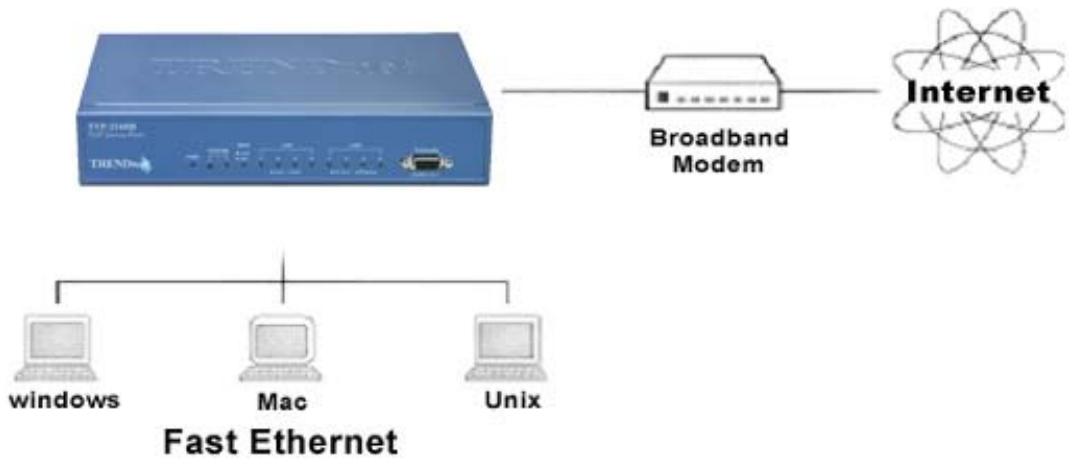
Figure 1: TVP-224HR
1.1 Features
The TVP-224HR is a cost-effective and highly reliable analog Voice over IP (VoIP) Gateway Router that offers toll quality voice and real-time fax data over IP networks. With its embedded architecture, the gateway is ideal for VoIP applications associated with Remote Office and Branch Office (ROBO) environments. With its built-in user-friendly interface, the gateway may be installed easily and conveniently to yield immediate cost savings. One VoIP Gateway supports up to four voice or Fax communications simultaneously.
Implemented with an efficient Real-Time Operating System (RTOS) and flash memory, the TVP-224HR provides upgradeable capabilities, so it may be programmed with updated firmware locally or via the network at any time. It comes equipped with remote management capabilities, configurable signaling to work with PBX, KTS, and/or telephone. The TVP-224HR utilizes advanced VoIP related technology. It includes various voice codecs and fax algorithms, echo cancellation, Voice Activity Detection (VAD), Comfort Noise Generation (CNG), and lost packet recovery algorithms.
Internet Access Features
- Shared Internet Access. All users on the LAN or WLAN can access the Internet through the TVP-224HR, using only a single external IP Address. The local (invalid) IP Addresses are hidden from external sources. This process is called NAT (Network Address Translation).
- DSL & Cable Modem Support. The TVP-224HR has a 100BaseT Ethernet port for connecting a DSL or Cable Modem. All popular DSL and Cable Modems are supported. SingTel RAS and Big Pond (Australia) login support is also included.
- PPPoE. The Internet (WAN port) connection supports PPPoE (PPP over Ethernet).
- Fixed or Dynamic IP Address. On the Internet (WAN port) connection, the TVP-224HR supports both Dynamic IP Address (IP Address is allocated on connection) and Fixed IP Address.
Advanced Internet Functions
- Special Internet Applications. Applications which use non-standard connections or port numbers are normally blocked by the Firewall. The ability to define and allow such applications is provided, to enable such applications to be used normally.
- Virtual Servers. This feature allows Internet users to access Internet servers on your LAN. The required setup is quick and easy.
- DMZ. One (1) PC on your local LAN can be configured to allow unrestricted 2-way communication with Servers or individual users on the Internet. This provides the ability to run programs which are incompatible with Firewalls.
- QoS. This feature "guarantees" better service to selected traffic on a network. The goal in configuring QoS is to give priority and attention to certain devices or services so that they can use the maximum available throughput and speed available on a certain network when it is needed.
LAN Features
- DHCP Server Support. Dynamic Host Configuration Protocol provides a dynamic IP address to PCs and other devices upon request. The TVP-224HR can act as a DHCP Server for devices on your local LAN and WLAN.
Configuration & Management
- Easy Setup. Use your WEB browser from anywhere on the LAN or WAN for configuration.
- Remote Management. The TVP-224HR can be managed from any PC on your LAN. And, if the Internet connection exists, it can also (optionally) be configured via the Internet using a web browser or telnet.
Security Features
- Password - protected Configuration. password protection is provided to prevent unauthorized users from modifying the configuration data and settings.
- NAT Protection. An intrinsic side effect of NAT (Network Address Translation) technology is that by allowing all LAN users to share a single IP address, the location and even the existence of each PC is hidden. From the external viewpoint, there is no network, only a single device - the TVP-224HR.
1.2 Networking Protocols
The TVP-224HR supports several industry-standard networking protocols required for voice communication. The following table describes these protocols.
| Networking Protocol | Description |
| Internet Protocol (IP) | IP is a messaging protocol that addresses and sends packets across the network. To enable IP protocol, the TVP-224HR must have a Real IP address, subnet, and gateway assigned to it. |
| Voice over IP Protocol (VoIP) | VoIP enables the TVP-224HR to transfer voice communications over an IP network. The TVP-224HR employs ITU-T H.323 protocol for setting up calls with one another. |
| Trivial File Transfer Protocol (TFTP) | TFTP allows you to transfer files over the network. The TVP-224HR implements a TFTP client allowing you to download new revision firmware from a TFTP server. The TFTP client requires a TFTP server in your network. |
| Real-Time Transport (RTP) | RTP is a standard for transporting real-time data over IP network. The TVP-224HR uses RTP protocol to send digitized and compressed voice packets. |
1.3 Package Contents
The contents of your product should contain the following items:
- TVP-224HR VoIP Gateway Router 4 port n
100-240V Power Adapter
9-pin straight through RS-232 cable
Printed Quick Installation Guide - User's guide (CD)
- RJ45 Cable
1.4 Front Panel
The front panel of the TVP-224HR contains a push button and LED indicators. The following figure illustrates the front panel of the TVP-224HR.

4-port TVP-224HR Front Panel
LED Indicators
The LED indicators on the front panel display the current status of the TVP-224HR as described in the following table:
| Indicator | Color | Activity | Indication |
| PWR | Green | On | Power is supplied to the gateway. |
| SYSTEM | Green | Blinking | The system is running. (Heartbeat LED) |
| LAN | |||
| • Act | Green | On | Data is being transferred on the LAN. |
| • Link | Green | On | The gateway is connected to LAN at 100Mb/s. |
| WAN | Off | The gateway is connected to LAN at 10Mb/s. | |
| • Link | Green | On | The gateway is connected to WAN. |
| • Act | Green | On | Data is being transferred on the WAN. |
| LINE | Green | Off | The line is idle. |
| Channels | On | The line is being used. | |
| 1-4 | Blinking | The line is ringing. |
Reset Button
There is a recessed push button located next to the SYSTEM LED. This button allows you to reset the TVP-224HR or force the TVP-224HR to enter firmware upgrade mode.
To reset the gateway, push a small, stiff object into the hole until the SYSTEM LED stops blinking, then release the button.
Powering on the gateway while pressing down the button for 5 seconds forces the TVP-224HR to enter download mode
1.5 Rear Panel
The rear panel of the TVP-224HR has four analog telephony ports, two FXO and two FXS ports offering flexible telephony interface usage. The FXS telephony interface ports may be connected to Subscriber Equipment, such as Telephones, Fax Machines, Cordless Phones, and Modems. FXO ports can be connected to PBX and local phone company Central Office (CO) lines. In addition to analog telephony interface ports, there is a power jack for power adapter connection on the rear panel.

WAN / LAN / Console Ports
The TVP-224HR is equipped with 1 WAN and 4 LAN Ethernet interfaces with 10/100 Mbps auto-negotiation, auto MDIX capability. The Ethernet ports are located on the rear panel.
Console
There is a 9-pin RS-232 interface port on the front panel. Their functions are described below:
| Port | Label | Function |
| 1x RJ45 | WAN | Connecting to Cable / ADSL Modem for Internet connection. |
| 4x RJ45 | LAN | Connecting the TVP-224HR to 10/100 Mbps Ethernet network |
| 9-pin RS-232 | User Console | Connecting the TVP-224HR to a VT-100 terminal or terminal emulator for configuring the TVP-224HR |
Chapter 2
Installing the TVP-224HR

This chapter gives information on how to install the TVP-224HR.
2.1 Network Requirements
For the TVP-224HR to successfully operate in your network, your network must meet the following requirements:
- A working 10/100 Base-T Ethernet. The TVP-224HR connects to the Internet via an Ethernet LAN.
- IP network that supports gateway, and subnet mask. You'll need a static IP address to assign the TVP-224HR or a DDNS account for your Dynamic IP.
2.2 Installing the TVP-224HR
Due to the TVP-224HR being used in a desktop configuration, ensure that the TVP-224HR is placed in a clean, well-ventilated, and vibration-free environment.
When the TVP-224HR is used, be certain that the unit is placed on a sturdy, flat surface, near a grounded power outlet. At least three inches of clearance must be provided on both sides of the TVP-224HR for good ventilation.
2.3 Connecting to the telephony devices
The 4 port TVP-224HR supports 2 FXO and 2 FXS. Each RJ11 port is for connecting to telephony devices.
The FXO port is designed for connecting to PBXs or local telephone company central office switches (CO).
The FXS port is designed for connecting to analog telephone sets, G3 fax machines.
Warning: connection of incorrect telephony devices to the ports on the TIM can cause permanent damage to the TIM and/or the TVP-224HR.
2.4 Connecting to the LAN Network
The 4x RJ45 LAN network ports on the rear panel supports 10/100 Mbps half-duplex connections to Ethernet. You can use either Category 3 or 5 straight-through UTP cable for 10 Mbps connections, but use Category 5 for 100 Mbps connections. Insert one end of the Ethernet cable into one of the 4 RJ45 ports on the rear panel of the TVP-224HR and other end of the cable to a network device / PC.
2.5 Assigning an IP address to the TVP-224HR
The IP address is the unique logical address identifying each IP node, such as the TVP-224HR, on an IP network. An IP address is a 32-bit number expressed as four decimal numbers from 0 to 255 separated by periods. The TVP-224HR can be configured with a fixed IP address, subnet mask and default gateway. The TVP-224HR can also be setup as a DHCP. Additionally, the TVP-224HR can also be configured to use PPPoE. With PPPoE, you will have a Dynamic IP but combined with Dynamic DNS, the TVP-224HR will automatically notify DynDNS of your changing IP Address and DynDNS will in turn, map it to your registered Domain Name. Consult your network manager to obtain a unique and static IP address for the TVP-224HR, the IP subnet mask and default gateway of your network, and fill out the work sheet in Appendix D before configuring the gateway. Procedures for assigning IP address, default gateway and subnet mask is available in Chapter 4.
2.6 Hardware Installation Procedures
1. Choose an Installation Site
- Select a suitable place on the network to install the TVP-224HR. Ensure the TVP-224HR and the DSL/Cable modem are powered OFF.
2. Connect LAN Cables
- Use standard LAN cables to connect PCs to the Switching Hub ports on the TVP-224HR. Both 10BaseT and 100BaseT connections can be used simultaneously.
- If required, you can connect any LAN port to another Hub. Any LAN port on the TVP-224HR will automatically function as an "Uplink" port when required. Just connect any LAN port to a normal port on the other hub, using a standard LAN cable.
- If desired, connect a PC (server) to the DMZ port. To use multiple servers, use a standard LAN cable to connect the DMZ port to a normal port on another hub, and connect your servers to the hub. PCs connected to the DMZ port are isolated from your LAN.
3. Connect WAN Cable
- Connect the Broadband modem to the WAN port on the TVP-224HR. Use the cable supplied with your Broadband modem. If no cable was supplied, use a standard LAN cable.
4. Power Up
Power on the Broadband modem.
- Connect one end of the power cord that came with the TVP-224HR to the power jack on the rear panel.
- Connect the other end of the power cord to an AC power outlet.
- The TVP-224HR will execute memory and application code testing automatically.
- Use only the power adapter provided. Using a different one may cause hardware damage
5. Check the LEDs
The Power LED should be ON.
The Systems LED should be blinking.
- For each LAN (PC) connection, the LAN Link/Act LED should be ON (provided the PC is also ON.)
The WAN LED should be ON.
- For each telephony device connection, the Line LED should be ON (provided the device is plugged in and receiver is off hook.)
Router Setup
This Chapter provides Setup details of the TVP-224HR.
Overview
This chapter describes the setup procedure for:
- Internet Access
LAN configuration
PCs on your local LAN may also require configuration. For details, see Chapter 4 - PC Configuration.
Other configuration may also be required, depending on which features and functions of the TVP-224HR you wish to use. Use the table below to locate detailed instructions for the required functions.
| To Do this: | Refer to: |
| Configure PCs on your LAN. | Chapter 4: PC Configuration |
| Check TVP-224HR operation and Status. | Chapter 5: Operation and Status |
| Use any of the following Internet features: Internet Access Configuration Dynamic DNS (Domain Name Server) Special Applications Virtual Servers Port Fowarding DMZ QoS | Chapter 6: Internet Features |
| Change any of the following Administration-related settings: Admin Login Access Control Remote Administration Upgrade Firmware | Chapter 7: Administration |
Configuration Program
The TVP-224HR contains an HTTP server. This enables you to connect to it, and configure it, using your Web Browser. Your Browser must support JavaScript. The configuration program has been tested on the following browsers:
- Netscape V4.08 or later
- Internet Explorer V4 or later
Preparation
Before attempting to configure the TVP-224HR, please ensure that:
- Your PC can establish a physical connection to the TVP-224HR. The PC and the TVP-224HR must be directly connected (using the Hub ports on the TVP-224HR) or on the same LAN segment.
The TVP-224HR must be installed and powered ON. - If the TVP-224HR's default IP Address (192.168.0.1) is already used by another device, the other device must be turned OFF until the TVP-224HR is allocated a new IP Address during configuration.
Using your Web Browser
To establish a connection from your PC to the TVP-224HR:
- After installing the TVP-224HR in your LAN, start your PC. If your PC is already running, restart it.
- Start your WEB browser.
- In the Address box, enter "HTTP://" and the IP Address of the TVP-224HR, as in this example, which uses the TVP-224HR's default IP Address:
HTTP://192.168.0.1
If you can't connect
If the TVP-224HR does not respond, check the following:
The TVP-224HR is properly installed, LAN connection is OK, and it is powered ON. You can test the connection by using the "Ping" command:
- Open the MS-DOS window or command prompt window.
Enter the command: ping 192.168.0.1
If no response is received, either the connection is not working, or your PC's IP address is not compatible with the TVP-224HR 's IP Address. (See next item.)
If your PC is using a fixed IP Address, its IP Address must be within the range 192.168.0.2 to 192.168.0.254 to be compatible with the TVP-224HR's default IP Address of 192.168.0.1. Also, the Network Mask must be set to 255.255.255.0. See Chapter 4 - PC Configuration for details on checking your PC's TCP/IP settings.
Ensure that your PC and the TVP-224HR are on the same network segment. (If you don't have a router, this must be the case.)
- You will be prompted for a username and password, as shown below.
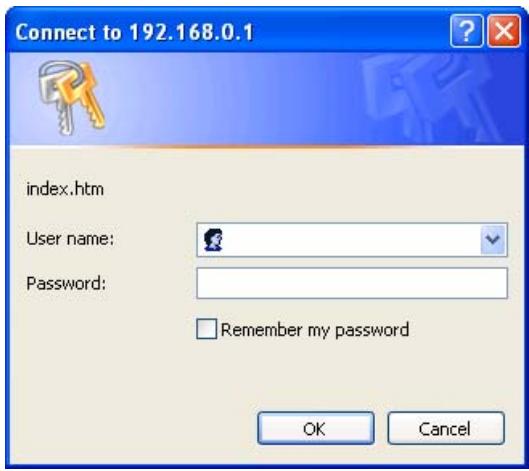
Figure 2: Password Dialog
- EnterUsername and Password. DefaultUserName and Password are "admin" and "123" respectively.
- These are the default values. Both the name and password can (and should) be changed, using the AdministrationPassword page. Once you have changed either the name or the password, you must use the current values.
Home Screen
After Logging on to the TVP-224HR, you will see the Home screen which is the System Status page. When you connect in future, you will see this screen when you connect. An example screen is shown below.
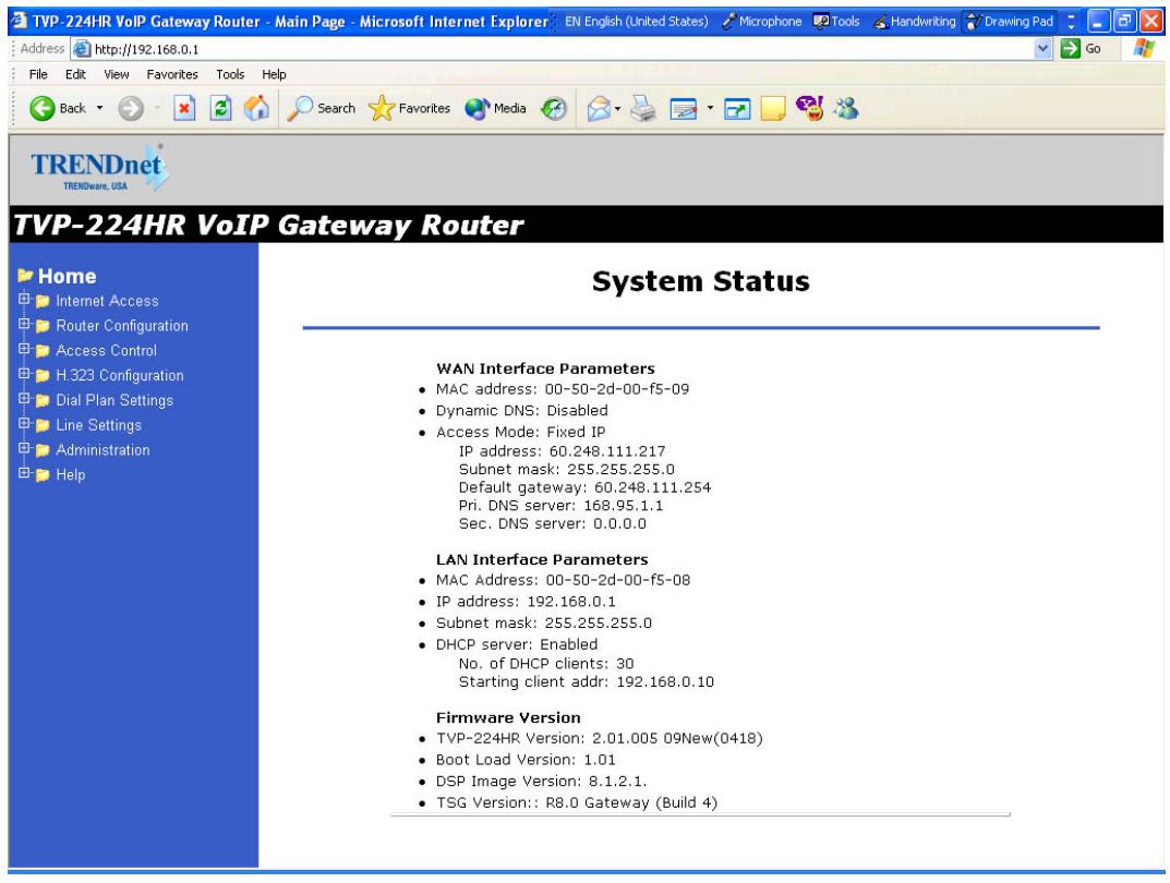
Figure 3: Home Screen
Navigation & Data Input
- Use the menu bar on the top of the screen, and the "Back" button on your Browser, for navigation.
- Changing to another screen without clicking "Save" does NOT save any changes you may have made. You must "Save" before changing screens or your data will be ignored.
LAN Configuration
From the main menu, navigate to Router Configuration. Click on the LAN sub menu. The LAN screen will appear as below.
TVP-224HR VoIP Gateway Router
Home
Internet Access
Router Configuration
LAN
Cps
DMZ
Bort Forwarding
F
Virtual Servers
Special Applications
Dynamic DNS
Access Control
H.323 Configuration
Dial Plan Settings
Line Settings
Administration
Administration
Help
LAN Configuration Settings
IP address
192.168.0.1
Subnet mask
255.255.255.0
DHCP Server
No. of client
30
Client start address
192.168.0.10
TFTP Server
Disable
Save The Changes
Figure 4: LAN Screen
Data - LAN Screen
| TCP/IP | |
| IP Address | IP address for the TVP-224HR, as seen from the local LAN. Use the default value unless the address is already in use or your LAN is using a different IP address range. In the latter case, enter an unused IP Address from within the range used by your LAN. |
| Subnet Mask | The default value 255.255.255.0 is standard for small (class "C") networks. For other networks, use the Subnet Mask for the LAN segment to which the TVP-224HR is attached (the same value as the PCs on that LAN segment). |
| DHCP Server | DHCP Server is by default, always on. The TVP-224HR will allocate IP Addresses to PCs (DHCP clients) on your LAN when they start up. If you are already using a DHCP Server, this setting must be Disabled, and the existing DHCP server must be re-configured to treat the TVP-224HR as the default Gateway. See the following section for further details. The Start IP Address and Finish IP Address fields set the values used by the DHCP server when allocating IP Addresses to DHCP clients. This range also determines the number of DHCP clients supported. See the following section for further details on using DHCP. |
Buttons
Save the changes
Save the data on screen.
DHCP
What does DHCP do?
A DHCP (Dynamic Host Configuration Protocol) Server allocates a valid IP address to a DHCP Client (PC or device) upon request.
- The client request is made when the client device starts up (boots).
- The DHCP Server provides the Gateway and DNS addresses to the client, as well as allocating an IP Address.
The TVP-224HR can act as a DHCP server. - Windows 95/98/ME and other non-Server versions of Windows will act as a DHCP client. This is the default Windows setting for the TCP/IP network protocol.
However, Windows uses the term Obtain an IP Address automatically instead of "DHCP Client".
- You must NOT have two (2) or more DHCP Servers on the same LAN segment. (If your LAN does not have other Routers, this means there must only be one (1) DHCP Server on your LAN.)
Using the TVP-224HR's DHCP Server
This is the default setting. The DHCP Server settings are on the LAN screen. On this screen, you can:
- Enable or Disable the TVP-224HR's DHCP Server function. Disable the DHCP by entering "0" in the number of clients field
- Set the range of IP Addresses allocated to PCs by the DHCP Server function.

You can assign Fixed IP Addresses to some devices while using DHCP, provided that the Fixed IP Addresses are NOT within the range used by the DHCP Server.
Using another DHCP Server
You can only use one (1) DHCP Server per LAN segment. If you wish to use another DHCP Server, rather than the TVP-224HR 's, the following procedure is required.
- Disable the DHCP Server feature in the TVP-224HR. Disable the DHCP by entering "0" in the number of clients field.
- Configure the DHCP Server to provide the TVP-224HR's IP Address as the Default Gateway.
To Configure your PCs to use DHCP
This is the default setting for TCP/IP under Windows 95/98/ME.
See Chapter 4 - Client Configuration for the procedure to check these settings.
Overview
For each PC, the following may need to be configured:
- TCP/IP network settings
- Internet Access configuration
Windows Clients
This section describes how to configure Windows clients for Internet access via the TVP-224HR.
The first step is to check the PC's TCP/IP settings.
The TVP-224HR uses the TCP/IP network protocol for all functions, so it is essential that the TCP/IP protocol be installed and configured on each PC.
TCP/IP Settings - Overview
If using the default TVP-224HR settings, and the default Windows TCP/IP settings, no changes need to be made.
- By default, the TVP-224HR will act as a DHCP Server, automatically providing a suitable IP Address (and related information) to each PC when the PC boots.
- For all non-Server versions of Windows, the default TCP/IP setting is to act as a DHCP client.
If using a Fixed (specified) IP address, the following changes are required:
The Gateway must be set to the IP address of the TVP-224HR
- The DNS should be set to the address provided by your ISP.

Do to NAT resolution issues, it is not recommended to use the TVP-224HR under another Router.
Checking TCP/IP Settings - Windows 9x/ME:
- Select Control Panel - Network. You should see a screen like the following:
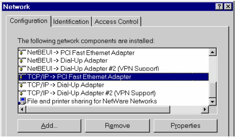
Figure 5: Network Configuration
- Select the TCP/IP protocol for your network card.
- Click on the Properties button. You should then see a screen like the following.
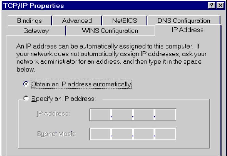
Figure 6: IP Address (Win 95)
Ensure your TCP/IP settings are correct, as follows:
Using DHCP
To use DHCP, select the radio button Obtain an IP Address automatically. This is the default Windows setting. Using this is recommended. By default, the TVP-224HR will act as a DHCP Server.
Restart your PC to ensure it obtains an IP Address from the TVP-224HR.
Using "Specify an IP Address"
If your PC is already configured, check with your network administrator before making the following changes:
- On the Gateway tab, enter the TVP-224HR's IP address in the New Gateway field and click Add, as shown below. Your LAN administrator can advise you of the IP Address they assigned to the TVP-224HR.
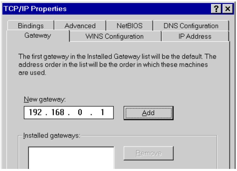
Figure 7: Gateway Tab (Win 95/98)
- On the DNS Configuration tab, ensure Enable DNS is selected. If the DNS Server Search Order list is empty, enter the DNS address provided by your ISP in the fields beside the Add button, then click Add.

Figure 8: DNS Tab (Win 95/98)
Checking TCP/IP Settings - Windows NT4.0
- Select Control Panel - Network, and, on the Protocols tab, select the TCP/IP protocol, as shown below.
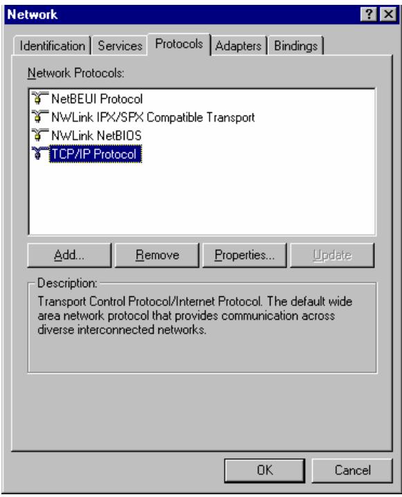
Figure 9: Windows NT4.0 - TCP/IP
- Click the Properties button to see a screen like the one below.
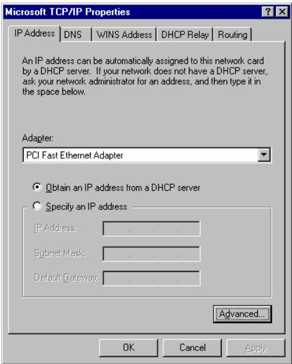
Figure 10: Windows NT4.0 - IP Address
- Select the network card for your LAN.
- Select the appropriate radio button - Obtain an IP address from a DHCP Server or Specify an IP Address, as explained below.
Obtain an IP address from a DHCP Server
This is the default Windows setting. Using this is recommended. By default, the TVP-224HR will act as a DHCP Server.
Restart your PC to ensure it obtains an IP Address from the TVP-224HR.
Specify an IP Address
If your PC is already configured, check with your network administrator before making the following changes.
-
The Default Gateway must be set to the IP address of the TVP-224HR. To set this:
-
Click the Advanced button on the screen above.
- On the following screen, click the Add button in the Gateways panel, and enter the TVP-224HR's IP address, as shown in Figure 11 below.
- If necessary, use the Up button to make the TVP-224HR the first entry in the Gateway's list.
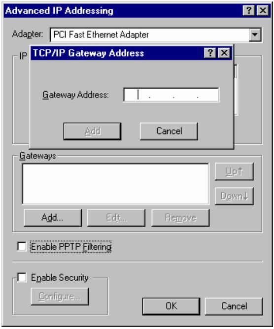
Figure 11 - Windows NT4.0 - Add Gateway
-
The DNS should be set to the address provided by your ISP, as follows:
-
Click the DNS tab.
- On the DNS screen, shown below, click the Add button (under DNS Service Search Order), and enter the DNS provided by your ISP.
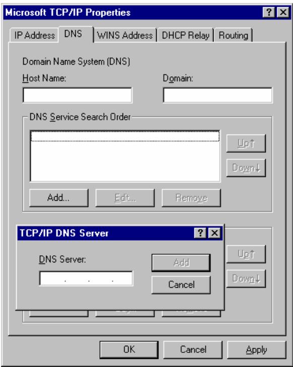
Figure 12: Windows NT4.0 - DNS
Checking TCP/IP Settings - Windows 2000:
- Select Control Panel - Network and Dial-up Connection.
- Right - click the Local Area Connection icon and select Properties. You should see a screen like the following:
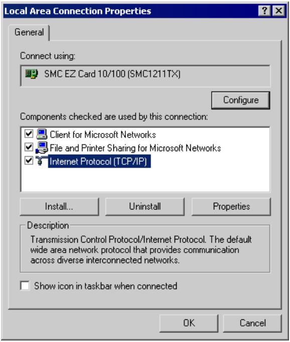
Figure 13: Network Configuration (Win 2000)
- Select the TCP/IP protocol for your network card.
- Click on the Properties button. You should then see a screen like the following.
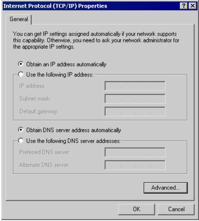
Figure 14: TCP/IP Properties (Win 2000)
- Ensure your TCP/IP settings are correct, as described below.
Using DHCP
To use DHCP, select the radio button Obtain an IP Address automatically. This is the default Windows setting. Using this is recommended. By default, the TVP-224HR will act as a DHCP Server.
Restart your PC to ensure it obtains an IP Address from the TVP-224HR.
Using a fixed IP Address ("Use the following IP Address")
If your PC is already configured, check with your network administrator before making the following changes.
-
Enter the TVP-224HR's IP address in the Default gateway field and click OK. (Your LAN administrator can advise you of the IP Address they assigned to the TVP-224HR.)
-
If the DNS Server fields are empty, select Use the following DNS server addresses, and enter the DNS address or addresses provided by your ISP, then click OK.
Checking TCP/IP Settings - Windows XP
- Select Control Panel - Network Connection.
- Right click the Local Area Connection and choose Properties. You should see a screen like the following:
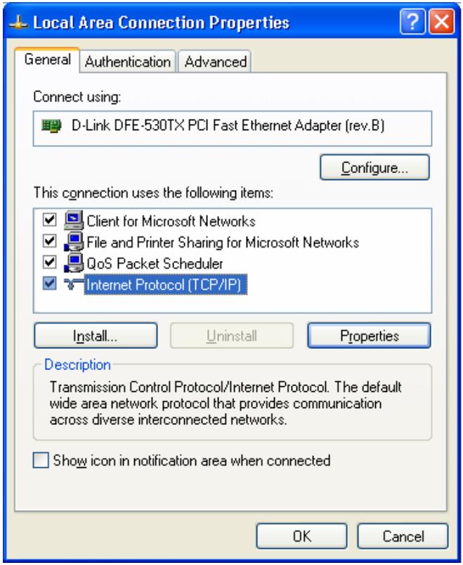
Figure 15: Network Configuration (Windows XP)
- Select the TCP/IP protocol for your network card.
- Click on the Properties button. You should then see a screen like the following.
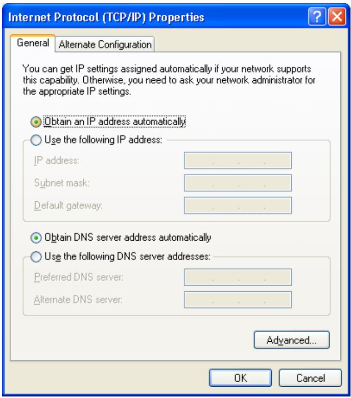
Figure 16: TCP/IP Properties (Windows XP)
- Ensure your TCP/IP settings are correct.
Using DHCP
To use DHCP, select the radio button Obtain an IP Address automatically. This is the default Windows setting. Using this is recommended. By default, the TVP-224HR will act as a DHCP Server.
Restart your PC to ensure it obtains an IP Address from the TVP-224HR.
Using a fixed IP Address ("Use the following IP Address")
If your PC is already configured, check with your network administrator before making the following changes.
- In the Default gateway field, enter the TVP-224HR's IP address and click OK. Your LAN administrator can advise you of the IP Address they assigned to the TVP-224HR.
- If the DNS Server fields are empty, select Use the following DNS server addresses, and enter the DNS address or addresses provided by your ISP, then click OK.
Internet Access
To configure your PCs to use the TVP-224HR for Internet access:
- Ensure that the DSL modem, Cable modem, or other permanent connection is functional.
- Use the following procedure to configure your Browser to access the Internet via the LAN, rather than by a Dial-up connection.
For Windows 9x/ME/2000
- Select Start Menu - Settings - Control Panel - Internet Options.
- Select the Connection tab, and click the Setup button.
- Select "I want to set up my Internet connection manually, or I want to connect through a local area network (LAN)" and click Next.
- Select "I connect through a local area network (LAN)" and click Next.
- Ensure all of the boxes on the following Local area network Internet Configuration screen are unchecked.
- Check the "No" option when prompted "Do you want to set up an Internet mail account now?"
- Click Finish to close the Internet Connection Wizard. Setup is now completed.
For Windows XP
- Select Start Menu - Control Panel - Network and Internet Connections.
- Select Set up or change your Internet Connection.
- Select the Connection tab, and click the Setup button.
- Cancel the pop-up "Location Information" screen.
- Click Next on the "New Connection Wizard" screen.
- Select "Connect to the Internet" and click Next.
- Select "Set up my connection manually" and click Next.
- Check "Connect using a broadband connection that is always on" and click Next.
- Click Finish to close the New Connection Wizard. Setup is now completed.
Accessing AOL
To access AOL (America On Line) through the TVP-224HR, the AOL for Windows software must be configured to use TCP/IP network access, rather than a dial-up connection. The configuration process is as follows:
- Start the AOL for Windows communication software. Ensure that it is Version 2.5, 3.0 or later. This procedure will not work with earlier versions.
- Click the Setup button.
- Select Create Location, and change the location name from "New Locality" to "TVP-224HR".
- Click Edit Location. Select TCP/IP for the Network field. (Leave the Phone Number blank.)
- Click Save, then OK.
Configuration is now complete. - Before clicking "Sign On", always ensure that you are using the "TVP-224HR" location.
Macintosh Clients
From your Macintosh, you can access the Internet via the TVP-224HR. The procedure is as follows.
- Open the TCP/IP Control Panel.
- Select Ethernet from the Connect via pop-up menu.
- Select Using DHCP Server from the Configure pop-up menu. The DHCP Client ID field can be left blank.
- Close the TCP/IP panel, saving your settings.
Note:
If using manually assigned IP addresses instead of DHCP, the required changes are:
- Set the Router Address field to the TVP-224HR's IP Address.
- Ensure your DNS settings are correct.
Linux Clients
To access the Internet via the TVP-224HR, it is only necessary to set the TVP-224HR as the "Gateway".
Ensure you are logged in as "root" before attempting any changes.
Fixed IP Address
By default, most Unix installations use a fixed IP Address. If you wish to continue using a fixed IP Address, make the following changes to your configuration.
- Set your "Default Gateway" to the IP Address of the TVP-224HR.
- Ensure your DNS (Name server) settings are correct.
To act as a DHCP Client (recommended)
The procedure below may vary according to your version of Linux and X -windows shell.
- Start your X Windows client.
- Select Control Panel - Network
- Select the "Interface" entry for your Network card. Normally, this will be called "eth0".
- Click the Edit button, set the "protocol" to "DHCP", and save this data.
-
To apply your changes
-
Use the "Deactivate" and "Activate" buttons, if available.
- OR, restart your system.
Other Unix Systems
To access the Internet via the TVP-224HR:
- Ensure the "Gateway" field for your network card is set to the IP Address of the TVP-224HR.
- Ensure your DNS (Name Server) settings are correct.
Chapter 5
Operation and Status
This Chapter details the operation of the TVP-224HR, the system status screen as well as the channel status screen
Operation
Once both the TVP-224HR and the PCs are configured, operation is automatic.
However, there are some situations where additional Internet configuration may be required:
- Applications which use non-standard connections or port numbers may be blocked by the TVP-224HR 's intrinsic firewall nature. You can define such applications as Special Applications to allow them to function normally. Refer to Chapter 6 - Internet Features for further details.
- Some non-standard applications may require use of the DMZ feature. Refer to Chapter 6 - Internet Features for further details.
System Status Screen
Use the Home link on the main menu to view this screen.
System Status
WAN Interface Parameters
MAC address: 00-50-2d-00-f5-09
Dynamic DNS: Disabled
- Access Mode: Fixed IP
IP address: 60.248.111.217
Subnet mask: 255.255.255.0
Default gateway: 60.248.111.254
Pri.DNS server:168.95.1.1
Sec.DNS server:0.0.0.0
LAN Interface Parameters
MAC Address: 00-50-2d-00-f5-08
- IP address: 192.168.0.1
- Subnet mask: 255.255.255.0
- DHCP server: Enabled
No. of DHCP clients: 30
Starting client addr: 192.168.0.10
Firmware Version
- TVP-224HR Version: 2.01.005 09New(0418)
- Boot Load Version: 1.01
DSP Image Version: 8.1.2.1. - TSG Version:: R8.0 Gateway (Build 4)
Figure 17: System Status Screen
Data - System Status Screen
| Wan Interface Parameters | |
| MAC Address | The hardware address of this device, as seen by remote devices on the Internet. (This is different to the hardware address seen by devices on the local LAN.) |
| Dynamic DNS | Enabled / Disabled |
| Access Mode | This indicates the current connection method. Fixed IP, DHCP or PPPoE |
| IP Address | This IP Address is allocated by the ISP (Internet Service Provider). |
| Subnet Mask | The subnet Mask (Network Mask) for the IP Address above |
| Default Gateway | The IP Address of the remote Gateway or Router associated with the IP Address above |
| Primary DNS Server | The IP Address of the Domain Name Server which is currently used. |
| Secondary DNS Server | The IP Address of a backup Domain Name Server which could be used if the Primary DNS Server fails. |
| LAN Interface Parameters | |
| MAC Address | The hardware address seen by devices on the local LAN. (This is different than hardware address of this device, as seen by remote devices on the Internet) |
| IP Address | The IP Address of the TVP-224HR. |
| Subnet Mask | The subnet Mask (Network Mask) for the IP Address above. |
| DHCP Server | This shows the status of the DHCP Server function - either "Enabled" or "Disabled". For additional information about the PCs on your LAN, and the IP addresses allocated to them, use the PC Database option on the Other menu. |
| No. of DHCP clients | This shows the possible number of Clients as chosen |
| Starting client addr | The starting IP address to be assigned by the DHCP Server |
| Firmware Version | |
| TVP-224HR Version | This displays the firmware version of the TVP-224HR. |
| Boot Version | The current boot version. |
h323 display_name = Customer
- h323 h245_term_type = 60
h323 rtp_port_base = 30000
- h323 out_fast_start = off
h323 in_fast_start = off
- h323 h245_tunneling = off
h323 cisco_t38 = on
- h323 callSignalPort = 1720
h323 nat_call = on
·h323 call_name =
h323 localalert = off
- h323 default_dtmf = H323 V2 Signal
- No Alternate IP Defined!
- h323 gk_mode = off
- h323 h245_timeout = 30000
·h323 term_id =
h323 gk_fail =
Chapter 6
Internet Features
This Chapter explains when and how to use the TVP-224HR's "Internet" Features.
Overview
The following advanced features are provided.
- Internet Access Configuration
DMZ - Packet filter
Dynamic DNS
Special Applications
Virtual Servers - Port Forwarding
Voice QoS
Internet Access Configuration
The Internet Access menu, has three submenus providing for three different types of internet connection. Fixed IP, DHCP and PPPoE. The first is Fixed IP as shown below.
TVP-224HR VoIP Gateway Router
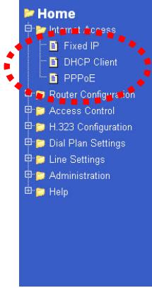
Figure 18: Internet Access Fixed IP Configuration Menu
Fixed IP Network Settings
IP Address
60.248.111.217
Subnet Mask
255.255.255.0
Default Gateway
60.248.111.254
Primary DNS server
168.95.1.1
Secondary DNS server
0.00.0
OK
Fixed / Dynamic IP Address
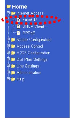
If your access method is "Fixed IP" (no login), a screen like the following example will be displayed when the "Fixed IP" button is clicked.
TVP-224HR VoIP Gateway Router
Fixed IP Network Settings

Figure 19: Connection Details - Fixed/Dynamic IP Address
Data - Fixed/Dynamic IP address Screen
| Internet | |
| IP Address | The IP Address of this device, as seen by Internet users. This address is allocated by your ISP (Internet Service Provider). |
| Subnet Mask | The Network Mask associated with the IP Address above. |
| Default Gateway | The IP Address of the remote Gateway or Router associated with the IP Address above. |
| DNS IP Address | The IP Address of the Domain Name Server which is currently used. |
| Secondary DNS Server | The IP Address of the Backup Domain Name Server if the primary should fail |
| Buttons | |
| OK | Click on Ok once your information has been filled in. You will also have to reboot the device in order for the changes to take effect. |
PPPoE Configuration
If using PPPoE (PPP over Ethernet), a screen like the following example will be displayed when the "PPPoE" button is clicked.
TVP-224HR VoIP Gateway Router
Home

Internet Access
Fixed IP
1 + u7 = 70%
自 PPPoE
Router configuration
Access Control
H.323 Configuration
Dial Plan Settings
Line Settings
Administration
Help
WAN PPPoE Configuration
Enable PPPoE
Service name
UserID
Password
Idle timeout in
seconds
IPCp fixed IP
address
Authentication
protocol
Transmit
bandwidth
MTU Size


0
0.0.0.0


Figure 20: PPPoE Configuration Screen
m = 311
1492
OK
Data - PPPoE Screen
| Connection | |
| Enable PPPoE | Yes / No |
| User Name | User Name as assigned by your ISP |
| Password | Password as assigned by your ISP |
| Idle timeout in seconds | An Internet connection is automatically made when required, and disconnected when idle for the time period specified by the "Auto-disconnect Idle Time-out". |
| IPCP fixed IP address | Default Value: 0.0.0 (Value should only be changed if advised to do so by Technical Support.) |
| Authentication Protocol | Default Value: pap(Value should only be changed if advised to do so by Technical Support.) |
| Transmit Bandwidth | Default Value: 0(Value should only be changed if advised to do so by Technical Support.) |
| MTU Size | MTU (Maximum Transmission Unit) value should only be changed if advised to do so by Technical Support. Enter a value between 1 and 1500. This device will still auto-negotiate with the remote server, to set the MTU size. The smaller of the 2 values (auto-negotiated, or entered here) will be used. For direct connections (not PPPoE or PPTP), the MTU used is always 1500. |
| Buttons | |
| OK | After entering data, click on OK to save settings. You will also have to reboot the device to make the settings take effect |
Special Applications
If you use Internet applications which use non-standard connections or port numbers, you may find that they do not function correctly because they are blocked by the TVP-224HR 's firewall. In this case, you can define the application as a "Special Application".
Special Applications Screen
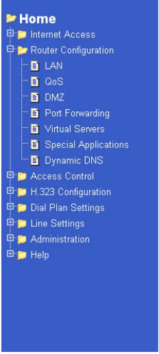
This screen can be reached by clicking the Special Applications submenu located under the Router Configuration main menu.
You can then define your Special Applications. You will need detailed information about the application; this is normally available from the supplier of the application. You can also reference the Common Port Setting page.
Also, note that the terms "Incoming" and "Outgoing" on this screen refer to traffic from the client (PC) viewpoint
TVP-224HR VoIP Gateway Router
Special APP Setup
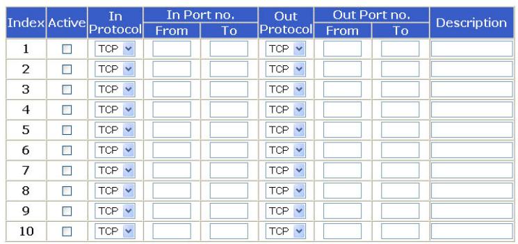

Figure 21: Special Applications Screen
Data - Special Applications Screen
Checkbox Description Incoming Ports No
Use this to Enable or Disable this Special Application as required.
Enter a descriptive name to identify this Special Application.
Type - Select the protocol (TCP or UDP) used when you receive data from the special application or service. (Note: Some applications use different protocols for outgoing and incoming data).
From - Enter the beginning of the range of port numbers used by the application server, for data you receive. If the application uses a single port number, enter it in both the "From" and "to" fields.
To - Enter the end of the range of port numbers used by the application server, for data you receive.
Outgoing Ports
Type - Select the protocol (TCP or UDP) used when you send data to the remote system or service.
From - Enter the beginning of the range of port numbers used by the application server, for data you send to it. If the application uses a single port number, enter it in both the "From" and "To" fields.
To - Enter the end of the range of port numbers used by the application server, for data you send to it. If the application uses a single port number, enter it in both the "From" and "To" fields.
Using a Special Application
- Configure the Special Applications screen as required.
- On your PC, use the application normally. Remember that only one (1) PC can use each Special application at any time. Also, when 1 PC is finished using a particular Special Application, there may need to be a "Time-out" before another PC can use the same Special Application. The "Time-out" period may be up to 3 minutes.

If an application still cannot function correctly, try using the "DMZ" feature.
DMZ
This feature, if enabled, allows one (1) device /
PC on your LAN to be exposed to all users on the
Internet.
This allows unrestricted 2-way communication between the "DMZ PC" and other Internet users or Servers.
This allows almost any application to be used on the "DMZ PC".
- The "DMZ PC" will receive all "Unknown" connections and data.
- If the DMZ feature is enabled, you must select the PC to be used as the "DMZ PC".

The "DMZ PC" is effectively outside the Firewall, making it more vulnerable to attacks. For this reason, you should only enable the DMZ feature when required.
Dynamic DNS (Domain Name Server)
This free service is very useful when combined with the Virtual Server feature. It allows Internet users to connect to your Virtual Servers using a URL, rather than an IP Address. This also solves the problem of having a dynamic IP address. With a dynamic IP address, your IP address may change whenever you connect, which makes it difficult to connect to you.
The Service works as follows:
- You must register for the service at www.dyndns.org using the dyndns.org domain.
-
After registration, follow the Service Provider's procedure to request a Domain Name, and have it allocated to you.
-
Enter your DDNS data on the TVP-224HR's DDNS screen (shown below).
- The TVP-224HR will then automatically ensure that your current IP Address is recorded and updated at the DDNS server.
If the DDNS Service provides software to perform this "IP address update"; you should disable the "Update" function, or not use the software at all.
- From the Internet, users will be able to connect to your Virtual Servers (or DMZ PC) using your Domain name, as shown on this screen.
Dynamic DNS Screen
Select Internet on the main menu, then Dynamic DNS, to see a screen like the following:
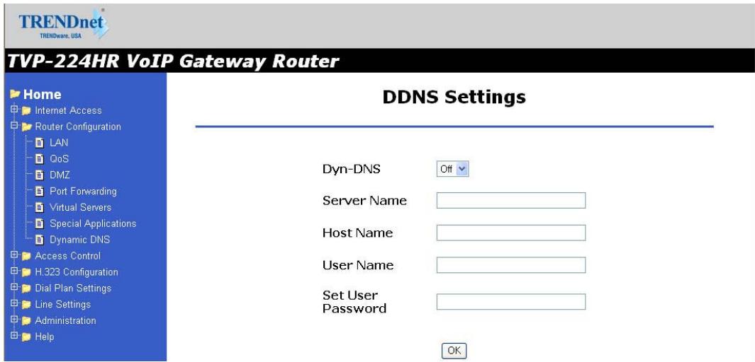
Figure 22: DDNS Screen
Data - Dynamic DNS Screen
| DDNS Service | |
| DDNS Service | You must register for the service at dyndns.org. Apply for a Domain Name, and ensure it is allocated to you. Details of your DDNS account (Name, password, Domain name) must then be entered and saved on this screen. This device will then automatically ensure that your current IP Address is recorded by the DDNS Service Provider. (You do NOT need to use the "Client" program provided by some DDNS Service providers.) |
| From the Internet, users will now be able to connect to your Virtual Servers (or DMZ PC) using your Domain name. | |
| DDNS Data | |
| Dyn DNS | On/Off |
| User Name | Enter yourUsername for the DDNS Service. |
| Password/Key | Enter your current password for the DDNS Service. |
| Domain Name (Hostname) | Enter the domain (hostname) name registered at www.dyndns.org. For instance, if you registered johnsmith.dyndns.org, please enter |
| johnsmith | |
| DDNS Status | This message is returned by the DDNS Server Normally, this message should be something like "Update successful" or "IP address updated". If the message indicates some problem, you need to connect to the DDNS Service provider and correct this problem. |
Virtual Servers / Port Forwarding
This feature allows you to make Servers on your LAN accessible to Internet users. Normally, Internet users would not be able to access a server on your LAN because:
- Your Server does not have a valid external IP Address.
- Attempts to connect to devices on your LAN are blocked by the firewall in this device.
The "Virtual Server" feature solves these problems and allows Internet users to connect to your servers, as illustrated below.
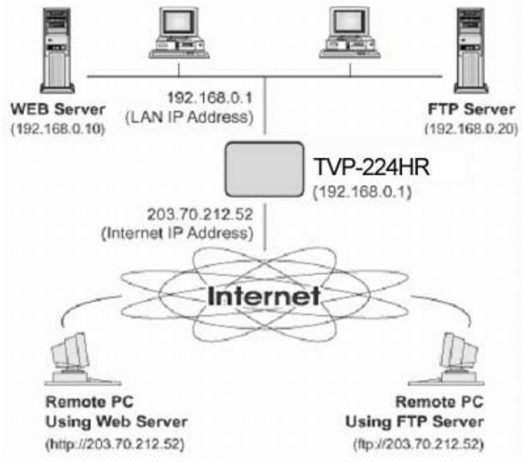
Figure 23: Virtual Servers
IP Address seen by Internet Users
Note that, in this illustration, both Internet users are connecting to the same IP Address, but using different protocols.
To Internet users, all virtual Servers on your LAN have the same IP Address. This IP Address is allocated by your ISP.
This address should be static, rather than dynamic, to make it easier for Internet users to connect to your Servers. However, you can use the DDNS (Dynamic DNS) feature to allow users to connect to your Virtual Servers using a URL, instead of an IP Address.
Virtual Servers Screen
The Virtual Servers screen is reached by the Virtual Servers link under the Router Configuration menu. An example screen is shown below.
TVP-224HR VoIP Gateway Router
Home
Internet Access
Router Configuration
LAN
COS
DMZ
Port Forwarding
Virtual Servers
Special Applications
Speclal spectrum Densin RNA
Dynamic DNS
口AccessControl
H.323 Configuration
Dial Plan Settings
Line Settings
□■Administration
Help
Virtual Server Setup
| Index | Active | Protocol | External Port | Internal IP | Internal Port |
| 1 | ☐ | TCP | ☐ | ☐ | ☐ |
| 2 | ☐ | TCP | ☐ | ☐ | ☐ |
| 3 | ☐ | TCP | ☐ | ☐ | ☐ |
| 4 | ☐ | TCP | ☐ | ☐ | ☐ |
| 5 | ☐ | TCP | ☐ | ☐ | ☐ |
| 6 | ☐ | TCP | ☐ | ☐ | ☐ |
| 7 | ☐ | TCP | ☐ | ☐ | ☐ |
| 8 | ☐ | TCP | ☐ | ☐ | ☐ |
| 9 | ☐ | TCP | ☐ | ☐ | ☐ |
| 10 | ☐ | TCP | ☐ | ☐ | ☐ |
OK
Figure 24: Virtual Servers Screen
Data - Virtual Servers Screen
| Virtual Server Data | |
| Checkbox | Use this to Enable or Disable this Special Application as required. |
| Protocol | Type - Select the protocol (TCP or UDP) used when you receive data from the special application or service. (Note: Some applications use different protocols for outgoing and incoming data). |
| External Port | Enter the port number used by the virtual server |
| Internal IP | Enter the IP Address of the virtual server. The PC must be running the appropriate Server software. |
| Internal Port | Enter the port number used by the virtual server |
Connecting to the Virtual Servers
Once configured, anyone on the Internet can connect to your Virtual Servers. They must use the Internet IP Address (the IP Address allocated to you by your ISP).
e.g.
http://203.70.212.52
ftp://203.70.212.52
It is more convenient if you are using a Fixed IP Address from your ISP, rather than Dynamic. However, you can use the Dynamic DNS feature, described in the following section, to allow users to connect to your Virtual Servers using a URL, rather than an IP Address.
Voice QoS
QoS is a popular feature that "guarantees" better service to selected traffic on a network. The goal in configuring QoS is to give priority and attention to certain devices or services so that they can use the maximum available throughput and speed available on a certain network when it is needed.
Voice QoS Screen
The Voice QoS screen is reached by the Voice QoS link under the Router Configuration menu. An example screen is shown below
TVP-224HR VoIP Gateway Router
Home
Internet Access
Router Configuration
LAN
QoS
DM7
D.
Port Forwarding
Virtual Servers
Special Applications
Dynamic DNS
Access Control
H202.05fotting
H.323 Configuration
Dial Plan Settings
Line Settings
Administration
Hole
Voice QoS Settings
Enable Voice QoS

Assured Bandwidth for Voice:

kbits/sec
Maximun Uplink Bandwidth Allowed (kbits/sec):


IP TOS

(2 Hex digit byte value)

Data - Voice QoS Screen
Voice QoS Data
| On / Off | Use this to Enable or Disable Voice QoS functionality as required. |
| Assured Bandwidth for Voice | Enter the amount of bandwidth you would like to reserve for VoIP packets. To determine how much bandwidth you will require, multiply the number of potential simultaneous connections (channels / ports) by the current codec you are implementing.G.711 PCM 64kbps + Packet Header information = 80±5 KbpsG.723.1A (5.3, 6.3kbps) + Packet Header information = 10kbps ±2 kbpsG.729AB (8kbps) = 12 ±4 kbpsDefault codec is G.729AB. Therefore, if all FXO and FXS ports are being used, (4 Ports) multiplied by the default compression codec G.729AB at 16kbps would yield roughly 72kbps. |
| Maximum Uplink Bandwidth allowed (kbits/sec) | In the Field you will first have to find your ISP's speed in your contract or on the ISP's webpage. The values for speed are usually given in kilo Bits per second [kb/s] as are the values to be entered into TVP-224HR. If you are given you Maximum Uplink Bandwidth in KB/s, To convert to kilo Bytes simply multiply the kilo Bytes by a value of 8 Example: Maximum Downstream: 96kB/s x 8 = 768kb/s Maximum Upstream: 16kB/S x 8 = 128kb/s |
| IP ToS | |
| Buttons | |
| OK | Click on this to save data entered. |
Chapter 7
Administration
This Chapter explains Password setup, remote Administration via Telnet or Web Browser firmware Upgrade using TFT as well as Access Control using Packet filters
Overview
Normally, it is not necessary to use these screens, or change any settings. These screens and settings are provided to deal with non-standard situations, or to provide additional options for advanced users.
The screens available are:
Administrative Password
This administrative screen allows you to change your password. It is recommended that you change the default password immediately.
Remote Admin
This feature allows you to manage the TVP-221HR via the Internet using your Web Browser or Telnet.
Upgrade Firmware
The firmware (software) in the TVP-221HR can be upgraded using your Web Browser.
Access Control
Administration Password Setup / Login
The Administration Password Page allows you to change your password on the TVP-224HR
TVP-224HR VoIP Gateway Router
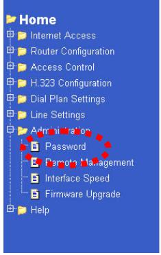
Administrator Password Setup
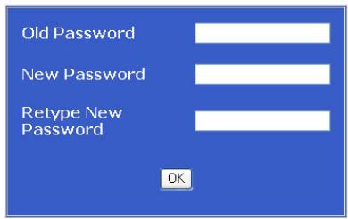
Figure 25: Administration Password Setup Screen
Data - Administration Password Setup
| Admin Login | |
| Old Password | Enter the old password |
| New password | Enter the new password here. If no password is required, leave this blank. If a password is set, the password will be required in order to change the configuration. |
| Retype New password | Enter the new password here again. This entry must match the value above. |
| Buttons | |
| OK | Click on OK to confirm new password |
① Note
Changes to the password from the Web UI and Telnet are effective immediately unless trying to use the new password set in Web UI and Talent from Console port. In this case, you would have to reboot the GW before the password would take effect.
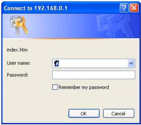
Figure 26: Password Dialog
Enter the default "UserID" and the "Password" you set on the Administration Password Setup screen above.
Remote Administration
Remote Administration allows you to connect to this interface via the Internet, using your Web browser or Telnet. By default, both services are activated.
TVP-224HR VoIP Gateway Router
Home
Internet Access
Router Configuration
Access Control
H323 Configuration
Dial Plan Settings
Line Settings
日
Adn
Password
Remote Management
Interface Speed
Firmware Upgrade
Help
Service Acess Configuration
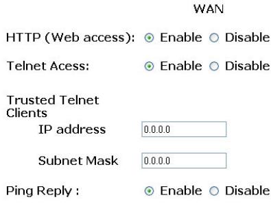

Figure 27: Remote Administration Screen
Data - Remote Administration Screen
| Information | |
| Information | To establish a connection from the Internet:6. Enable Remote Administration and configure this screen.7. From a remote location, start your Browser.8. In the "Address" or "Location" field, enter "HTTPS / "/" (NOT "HTTP / "/"), the Internet IP address of this device (NOT the LAN IP address), and the port number, as follows:HTTPS://ip_address:port_numberWhere:ip address is the Internet IP address of this device.port number is the port number assigned on this screen.9. You should then be prompted for the password for this device.(You must assign a password!) |
| Settings | |
| HTTP | Check this to allow web administration/management via the Internet. (To connect, see above).If Disabled, this device will ignore management connection attempts from the Internet. |
| Telnet | Check this to allow Telnet administration/management via the Internet. (To connect, see above).If Disabled, this device will ignore management connection attempts from the Internet. |
| IP Address | To manage this device via the Internet, you need to know the IP Address of this device, as seen from the Internet. This IP Address is allocated by your ISP. However, if you are using a Dynamic IP Address, this value can change each time you connect to your ISP.There are 2 solutions to this problem:Have your ISP allocate you a Fixed IP address.Use the DDNS feature (Internet menu) so you can connect using a |
| Domain Name, rather than an IP address. | |
| |Trusted Telnet Clients | This allows you to restrict remote access by IP address. To enable, enter the IP address of the trusted client. |
| Ping Reply | If enabled, this service allows the TVP-224HR to reply when pinged. |
To connect from a remote PC via the Internet
- Ensure your Internet connection is established, and start your Web Browser.
- In the "Address" bar, enter "HTTPS://" followed by the Internet IP Address of the TVP-224HR. If the port number is not 80, the port number is also required. (After the IP Address, enter":" followed by the port number.) e.g.
HTTPS://123.123.123.123:8080
This example assumes the WAN IP Address is 123.123.123.123, and the port number is 8080.
Upgrade Firmware
Use this screen to upgrade your TVP-224HR's firmware.
- You must download the required firmware file, and store it on a TFTP Server.
- During the upgrade process, all existing Internet connections will be terminated.
The upgrade process must NOT be interrupted!.
TVP-224HR VoIP Gateway Router
Firmware Update Settings
TFTP Server IP


Firmware Name


Figure 28: Upgrade Firmware Screen
Update
Caution: Please do not interrupt the firmware update process. Disruption of the update process could result in permanent damage to your TVP-224HR Gateway. Please refrain from performing other tasks during this process.
Data – Upgrade Firmware Screen
| Upgrade Firmware | |
| Upgrade File | Click the "Browse" button and browse to the location on your TFTP Server where you stored the firmware upgrade file. Select this file. |
| TFTP Server IP | Enter the IP address of the TFTP Server. |
| Update | Click this button to start the Firmware upgrade. Note that any users accessing the Internet via the TVP-224HR will lose their connection. When the upgrade is finished, the TVP-224HR will restart, and this management connection will be unavailable during the restart. |
| Cancel | Cancel does NOT stop the Upgrade process if it has started. It only clears the input for the "Upgrade File" field. |
To perform the Firmware Upgrade:
- Click the "Browse" button and navigate to the location of the upgrade file.
- Select the upgrade file. It's name will appear in the Upgrade File field.
- Click the "Update" button to commence the firmware upgrade.

The TVP-224HR is unavailable during the upgrade process, and must restart when the upgrade is completed. Any connections to or through the TVP-224HR will be lost.
Access Control
This feature is accessed by the navigating to the Access Control menu.
The Access Control feature allows administrators to restrict the level of Internet Access available to PCs on your LAN. With the default settings, everyone has unrestricted Internet access.
To use this feature:
- Set the desired restrictions on the "Default" group. All PCs are in the "Default" group unless explicitly moved to another group.
- Set the desired restrictions on the other groups ("Group 1", "Group 2", "Group 3" and "Group 4") as needed.
- Assign PC to the groups as required.

Restrictions are imposed by blocking "Services", or types of connections. Common Services have not been re pre-defined. Please see common port assignment for reference to common services.
Access Control Screen
To view this screen, select the Access Contro/Groups link from the main menu.
TVP-224HR VoIP Gateway Router
Home
Internet Access
Router Configuration
Access Control
Workgroup
- Packet Filter Table
H.323 Configuration
Dial Plan Settings
Line Settings
Administration
Help
Workgroup Setting Menu
The Access Control feature allows administrators to restrict specific service or Internet Access by individual PCs. These restrictions apply only to traffic on the WAN port; local (LAN) traffic is not affected.
Select a Workgroup number 1
Description
Operation Add Address type IP
Address
OK
Figure 29: Access Control Screen
Data - Access Control Screen
| Group | |
| Workgroup Number | Select the desired Group. Groups are named "Default", "Group 1", "Group 2", "Group 3" and "Group 4", and cannot be re-named. |
| Description | Enter the reference name / description of the workgroup. |
| Address Type IP or MAC Address | Use the Add/Delete/list scroll with the IP or MAC address field to create a group. If the current group is "Default", then members can not be added or deleted. This group contains PCs not allocated to any other group. To remove PCs from the Default Group, scroll to delete and enter the IP or MAC address you wish to delete To assign PCs to the Default Group, delete them from the Group they are currently in |
| Buttons | |
| OK | Click on OK to confirm new data |
After creating a group, you can start populating the group with packet filter restrictions. Below, please see the Packet Filter Screen.
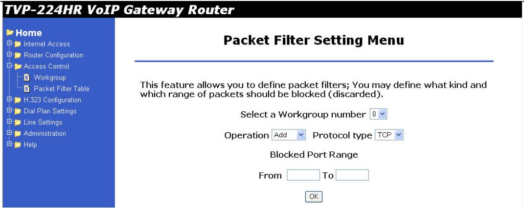
| Packet Filter | |
| Workgroup Number | Select the group you wish to apply the filter too |
| Add/Delete/List | Pick the operation you would like to perform to the IP or MAC address |
| TCP/UDP/Both | Choose the protocol you would like to filter |
| Block Range Port | Enter the port you would like to block. See below for common port assignments |
Common Port Assignment
These are common services / applications and the ports they use for network access.
| Services | Notes | Port Numbers |
| HTTP | 80 | |
| FTP | 21 | |
| TELNET | 23 | |
| POP3 | 110 | |
| SMTP | 25 | |
| mIRC | None | |
| NTP | 123 | |
| PPTP | 1723 | |
| Applications | Notes | Port Numbers |
| AOL | 5190 - 5193 | |
| AOL Instant Messenger (AIM) | 5190 | |
| AOL ICQ | 5190, dynamic > 1024 | |
| ICQ Firewall Settings | ||
| BAYVPN | 500 | |
| CarbonCopy32 | 1023 - 1680 | |
| CITRIX | 1494 | |
| Cu-SeeMe | Cornell 1.1 | 7648 |
| Direct Connect | 375 - 425 | |
| FW1VPN | 259 | |
| ICQ | For file transfer: ICQ -> Preference > Connections > Firewall. Set timeout to 80 seconds. | None for chat |
| IPTV | Cisco IPTV 2.0.0 | None |
| Laplink | 1547 | |
| Lotus Notes | 1352 | |
| MSN Messenger (Including Voice) | See this Microsoft Link for detailed info, including Windows 2000 Problems | 6901& 6891-6900 |
| NetMeeting | NetMeeting 2.1 and 2.11 | 1720 |
| How to Establish NetMeeting Connections Through a Firewall | 1503 | |
| PC Anywhere | Host must be on the LAN side and set. | 22 |
| 5631 - 5632 | ||
| RealPlayer | RealPlayer G2 | None |
| Remote Anything | 3996 - 4000 | |
| Shiva VPN | Set the mobile option to be your public IP address. | 2233 |
| Virtual Network Computing | 5500 | |
| 5800 | ||
| 5900 | ||
| VDOLive | None | |
| Vonage VoIP Phone Service | 5060 - 5070 | |
| 10000 - 25000 | ||
| Games | Notes | Ports |
| Age of Empires II | 23978 | |
| Aliens vs. Predator | 80 | |
| 2300 - 2400 | ||
| 8000 - 8999 | ||
| Asheron's Call | May need to open MSN DX ports. | 9000 - 9013 |
| Baldur's Gate | 15000 | |
| Black and White | 2611 - 2612 | |
| 6500 | ||
| 6667 | ||
| 27900 | ||
| Civilization 3 | Consult this page (You'll have to click through an ad.) | 80 |
| 6500 | ||
| Civilization Conquests users should also consult the manual, starting p. 47. | 6667 | |
| 13139 | ||
| 27900 | ||
| 28900 | ||
| 29900 | ||
| 29901 | ||
| Dark Reign 2 | 26214 | |
| Delta Force | 3100 | |
| 3568 | ||
| 3999 | ||
| Dune 2000 | 1140 - 1234 | |
| 4000 | ||
| Dungeon Siege | 19271 | |
| Elite Force | 26000 | |
| 27500 | ||
| 27910 | ||
| 27960 | ||
| Everquest | 1024 - 6000 | |
| 7000 | ||
| F-22 Lightning 3 | 4533 - 4660 | |
| Fighter Ace II | 50000 - 50100 | |
| Fighter Ace II (DX) | 2300 - 2400 | |
| 47624 | ||
| 50000 - 50100 | ||
| Half Life | 27015 | |
| Heretic II | 28910 | |
| Hexen II | Each computer must use a different port number. Add 1 for each player starting with 26900. | 26900 (+1 for each player) |
| KALI | Each computer must use a different port number. Add 1 for each player starting with 2213. | 2213 (+1 for each player) |
| 6666 | ||
| MSN Game Zone | 6667 | |
| 28800 - 29000 | ||
| MSN Game Zone (DX) | 2300 - 2400 | |
| 47624 | ||
| Myth | 3453 | |
| Need for Speed | 9442 | |
| Need for Speed 3 | 1030 | |
| Outlaws | 5310 | |
| Quake III | Each computer uses a different port number. Add 1 for each player starting with 27660. | 27660 (+1 for each player) |
| Rainbow Six | 2346 | |
| Rogue Spear | 2346 | |
| StarCraft | 6112 | |
| Tiberian Sun | 1140 - 1234 | |
| 4000 | ||
| Ultima | 5001 - 5010 Game | |
| 7775 - 7777 Login | ||
| 8888, 9999 Patch | ||
| 8800 - 8900 Messenger | ||
| 7875 Monitor | ||
| Unreal Tournament | Need to modify the [UWeb.WebServer] section of the server.ini file: Set ListenPort to 8080; Set ServerName to the Public IP of your router. | 7777 (game) |
| 7778 (server) | ||
| 7779 - 7783 (UdpLink) | ||
| 27900 (server query) | ||
| 8080 (UT Server Admin) | ||
| XBox | There are known problems with XBox Live Network, see Cannot Log On XBox with Router | 88 |
| 3074 | ||
| (XBox incorrectly says this is unnecessary in all cases.) | ||

PCs not assigned to any group will be in the "Default" group.
PCs deleted from any other Group will be added to the "Default" group.
Chapter 8

TVP-224HR Telephony
Concepts
The TVP-224HR enables the transmission of voice and fax traffic over any IP network by digitizing voice and fax signals, encapsulating the information within IP packets, and then sending the packets across the IP network
8.1 How the TVP-224HR Operates
- The TIM inside the TVP-224HR digitizes analog voice signals at 8 Kbps.
-
TVP-224HR system software handles the:
-
Capture of telephone number presented as DTMF tones.
- Mapping the telephone number to the IP address of remote VoIP Gateway.
- Setting up calls with remote TVP-224HRs utilizing H.323 call control protocol.
-
Digitizing, compressing and encapsulating the voice into IP packets and transmission of the IP packets onto the Ethernet LAN.
-
The TVP-224HR router forwards the IP packets across the WAN, where they will be received by another VoIP Gateway at the remote.
- The process is reversed at the remote VoIP Gateway.
8.2 ATPM
To allow you to easily dial a telephone or fax on the network, the TVP-224HR maps a series of dialed digits to the IP address of the remote TVP-224HR whose phone or fax you are calling. This mapping information is contained in a database inside each TVP-224HR called the dial plan.
Based on the dial plan, the Address Translation and Parsing Manager (ATPM) inside the TVP-224HR maps telephony numbers to IP addresses of remote VoIP Gateways. The ATPM collects telephone number dialed by users, decides whether the dial string is part of the dial plan and, if it is, maps it to a remote TVP-224HR / TVP-224HR. When the call is set up to the destination, a sub-string of the original dial string will be sent along to the remote VoIP Gateway.
8.3 Destination
The destination is where a call is terminated. Typically, for inbound calls from the IP network, the TVP-224HR terminals the call at one of the telephony ports. The
destination for the call is the telephony port where the call terminated. For calls initiated from telephony ports, the TVP-224HR forwards the call to a remote TVP-224HR/TVP-224HR via IP network, and the remote TVP-221H/TVP-224HR terminates the call. The destination of the call is the remote TVP-224HR/TVP-224HR.
8.4 Hunt Group
Instead of directly mapping a phone number to a destination, the ATPM first maps the phone number to a group of destinations known as a Hunt Group. A hunt group is a group of destinations that are equivalent. For example, the customer support group of a company might have 20 people who can handle support calls. Access to customer support is through a single phone number but the next available support person is actually connected upon each incoming call. These 20 phones would be configured as a hunt group. A hunt group consists of a phone number and a list of destinations (members of the group). When an incoming phone number matches the phone number of the hunt group, the TVP-224HR attempts to terminate the call at each of the destinations in the hunt group, one at a time until a call is successfully completed.
Every destination that can be reached by dialing a phone number is a member of at least one hunt group. When an address is presented to ATPM for lookup, the output is a hunt group ID number. As a second step, the hunt group ID is presented to ATPM to get the list of members. To effectively bypass the hunt group feature, simply assign a unique hunt group number to a single destination. In effect, the Hunt Group will just have this one member.
8.5 Dial Plan
The dial plan is a database inside the TVP-224HR that allows the ATPM to map telephone numbers dialed to IP addresses of remote VoIP Gateways. The dial plan consists of three tables; destination table, hunt group table and the address table. Users need to setup these tables in order for the TVP-224HR to process calls to remote VoIP Gateways.
Address Table
The address table maps a phone number to a hunt group. The table contains entries that specify the following information:
Telephone number
The hunt group the phone number maps to.
- The minimum number of digits to collect before the ATPM starts address lookup.
- The maximum number of digits the ATPM collects before it considers the dial string is complete.
Number of digits forwarded to the destination.
- Address table sample:
| Address Entry | Hunt Grp_Id | Min. Digits | Max. Digits | Prefix strip | Prefix Address |
| 201 | 3 | 3 | 3 | 3 | None |
| 301 | 4 | 3 | 3 | 3 | None |
| 8 | 1 | 3 | 3 | 0 | None |
| 0 | 1 | 1 | 1 | 0 | None |
| 20 | 11 | 5 | 5 | 2 | None |
Hunt Group Table
The hunt group table maps a hunt group to a list of destinations. Hunt group sample
| Hunt Group ID | Hunt Type | # of Dest ID(s) | Dest. ID(s) |
| 1 | 2 | 1 | 1 |
| 3 | 2 | 1 | 3 |
| 4 | 2 | 1 | 4 |
| 11 | 2 | 1 | 11 |
Destination Table
The destination table maps a destination to a telephony port or the IP address of a remote TVP-224HR.
Destination table sample
| Dest ID | Mode | Destination |
| 1 | Local | Port = 0 |
| 3 | Local | Port = 2 |
| 4 | Local | Port = 3 |
| 11 | H.323 | Dest = 192.168.0.55/1720 TCP |
8.6 DTMF Relay
Voice from PSTN is compressed by the TVP-224HR before it is sent across the IP network and then decompressed by the destination VoIP gateway. The voice codecs supported by the TVP-224HR are designed for ideally compressing and decompressing human voice. If the compression / decompression process is performed on DTMF tone which needs to be conveyed across IP network, distortion might be too significant to be cognizable on the receiving end. To overcome the shortcoming that the voice codecs may have encoding DTMF tone, the TVP-224HR encodes DTMF tone into special packets. The packets are then sent to the destination VoIP Gateway via a separate IP connection. The destination VoIP Gateway decodes the packets, generates the DTMF tone, and then sends the
tone to the PSTN. This method in which the TVP-224HR handles DTMF tone is so called DTMF relay.
The TVP-224HR handles DTMF relay per H.323 specifications. Certain third party VoIP devices may handle DTMF relay per IMTC standard. For the TVP-224HR to interoperate with those VoIP devices, users need to specify which remote VoIP devices use IMTC conforming DTMF relay technique. Refer to CLI command Error! Reference source not found. on Chapter 8 for detailed information on how to select DTMF relay mode.
8.7 Voice CODECs
Voice codecs supported by the TVP-224HR include G.711, G.723.1 5.3kbps, G.723.1 6.3kbps and G.729 AB. When setting up a call, two VoIP Gateways automatically negotiate with each other until an agreement on codec is determined.
Chapter 9

Configuring VoIP from a Web
Browser
This chapter explains procedures for configuring the TVP-224HR from a web browser.
9.1 HTTP setting mode
This section describes the processes for setting up the VoIP Gateway once it has been installed. Java enabled browsers including Microsoft Explorer version 4 or higher, or Navigator version 4.5 or higher can be used in this section to view and change parameters.
In the Address box, enter the following:
- http://192.168.0.1 (This is the default IP in the gateway from factory)
- Press enter to confirm and you should find the screen below.
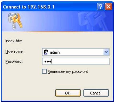
- The User name is admin (all lower case). Password is 123. Both admin and 123 are default strings from factory. For security reasons, please change and memorize the new password after this first setup.
- Click "OK". The main screen will appear as below.
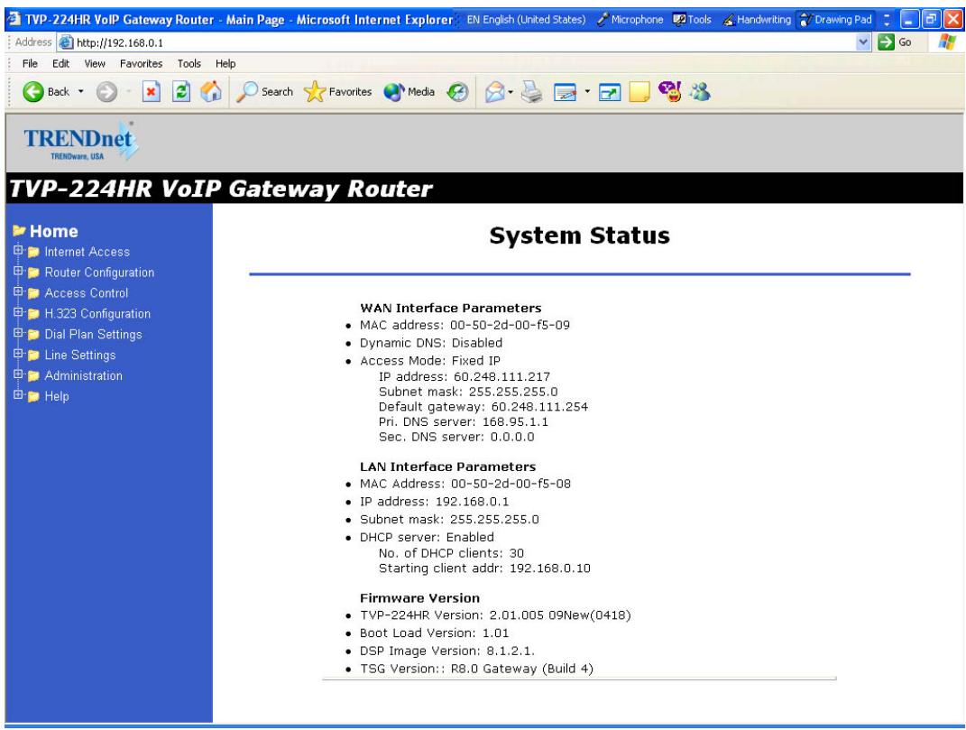
Main Menu Function Briefings
| Home | View System Status |
| H.323 Configuration | Set H.323 Parameters |
| Dial Plan Settings | Links to dial plan setting / entry / store / clear / restore pages. You should complete the dial Plan work sheets before working in this menu. |
| Line Settings | Set Line Settings including Channel Status, Codec Selection, Common Parameters, Channel Parameters and Telephony Ports |
| Administration | Set Password, Telnet Access, Interface Speed |
| Status | View current System Status |
| Help | Definitions of Graphical User Interface Terms and Parameters for Dial Plan Setup, H.323 Configurations, DDNS |
| Manual | Link to Trendware FTP Website, online |
user manual and support materials.
System Status
Select Home
In order to view the System Status page, please navigate to Home.
The System Status page will display the following parameters:
Firmware Version
TVP-224HR VoIP Gateway Version:
- Boot Loader Version:
- RTOS Version:
H.323 Stack Version:
DSP image Version:
TSG Version:
LAN Interface Parameters
IP precedence:
- Ethernet MAC address:
IP address:
- Subnet mask:
- Default gateway:
9.2 H.323 Configuration
H.323 Status Page
This page lists all current settings for H.323 Parameters.
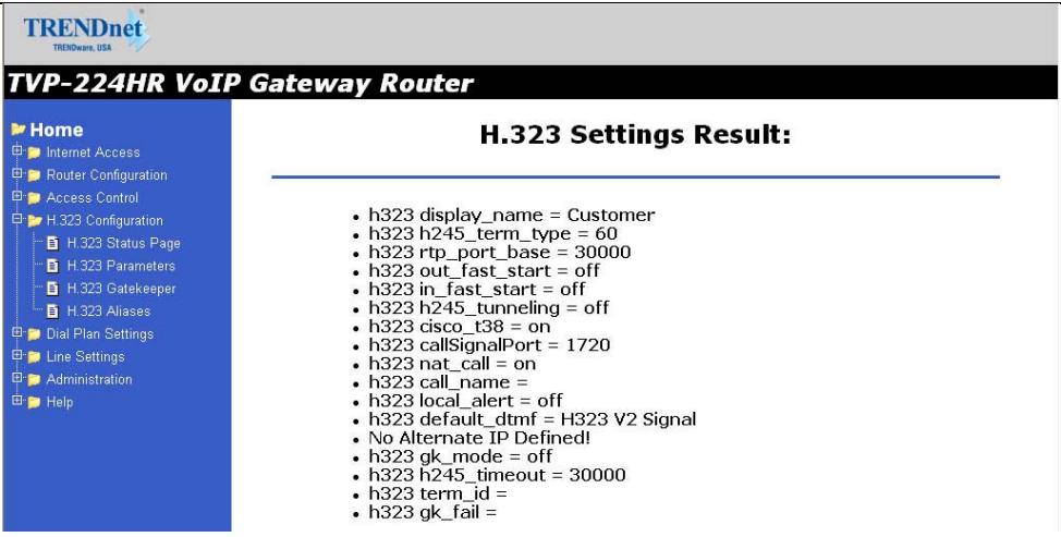
H.323 Parameters
For the most part end users will not be using these functions / features and / or should use the default settings. For more information please see the Advanced User Manuals or consult with your Systems Integrator
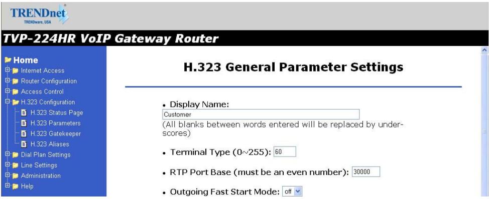
- Display Name: The default string is "Customer".
This field is to set the display name information that is carried in the H.323 setup messages. Up to 48 characters can be entered.
- Terminal Type: The default value is 60.
This field is to set the H.245 terminal type, which is used as part of the master/slave determination process of H.245. Typically, setting a value of less than 50 will force slave operation, and a value of greater than 200 will force the master operation. For more details, please refer to H.323-related standard documents.
- RTP Port Base: The default value is 30000.
This field is to select the starting port number for assignment of RTP and RTCP ports. According to the H.323 specification, RTP port number should be even in value, and the RTCP port number should be one greater than the RTP port. Typically, numbers from 0 to 1023 are reserved on most systems.
- Outgoing Fast Start: The default setting is off.
This field is to enable or disable the Fast start mode on the outgoing side of the link. - Incoming Fast Start: The default setting is off.
This field is to enable or disable the Fast start mode on the incoming side of the link. You'll have to reboot the system to make your changes active! Frame Rate = 2 frames/packet - Auto-Answer: Enables quick H.225 to H.245 transition without waiting for receiver picking up the phone, default is on
- NAT Call Mode: Enables calls from remote sites which use NAT routers with private IP networks behind, default is on
- Default DTMF Mode: H323 V2 Signal or IMTC. The default is H323 V2 Signal
- DNS IP Address
- Alternate DTMF IP Address
- DTMF Duration: default is 300
Gatekeeper
This page is home to many specific H.323 Gateway / Gatekeeper functions / features. For the most part end users will not be using these functions / features and / or should use the default settings. For more information please see the Advanced User Manuals or consult with your Systems Integrator The primary function of the gatekeeper component is to provide address translation services. This function converts external (telephone number) addresses and alias (name) addresses to network addresses, allowing users to maintain the same telephone numbers or alias addresses regardless of changes to their network addresses.
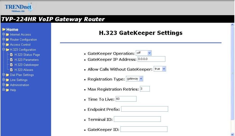
- Gate Keeper Mode: The default setting is off. This field is to select the co-operation mode with some other gatekeeper(s). Three options are available:
i. Off: Disables gatekeeper co-operation,
ii. Auto: Enables auto-discovery of the gatekeeper
iii. Manual: Enables gatekeeper co-operation in manual operation (the gatekeeper address must be properly assigned).
The following fields must be filled in when Gate Keeper Mode is set to either auto or manual.
- Gate Keeper Address: Specify the gatekeeper address when configured to manual mode. When auto mode is desired, this field should be set to auto
- Allow Calls Without Gate Keeper: This field is to inform the H.323 stack to allow calls when the endpoint is not registered with a gatekeeper.
- Registration Type: This field is to set the endpoint registration type. This specifies how the endpoint will register itself with the gatekeeper.
- Max Registration Retries: This field is to control how many registration attempts will be made before the endpoint considers itself to have failed registration.
- Time To Live:
- Endpoint Prefix: This command is used to set the H.323 prefix that the TVP-224HR uses when registering to an H.323 gatekeeper.
- Terminal ID: To specify GW's ID.
9. GateKeeper ID: To specify Gate Keeper's ID.
You'll have to reboot the system to make your changes take effect!
Aliases
For the most part end users will not be using these functions / features and / or should use the default settings. For more information please see the Advanced User Manuals or consult with your Systems Integrator
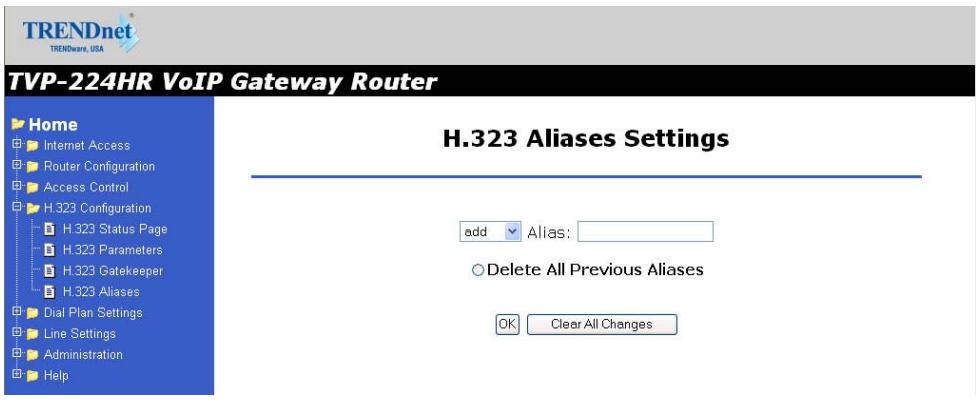
Alias: This field is to create or delete aliases that are registered with the gatekeeper.
The primary function of the gatekeeper component is to provide address translation services. This function converts external (telephone number) addresses and alias (name) addresses to network addresses, allowing users to maintain the same telephone numbers or alias addresses regardless of changes to their network addresses.
9.3 Dial Plan Settings
Dial Plan Setup
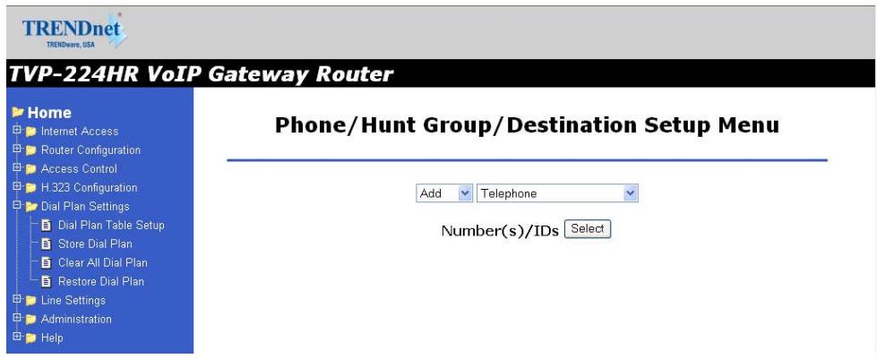
Using the function scroll bar on the right, you are able to Add, Delete, Find or List data to/from one of 3 tables (While it may appear that there are 5 tables, Remote Destination IP, Remote_Host_Name, and Local_Destination Channel are all part of the Destination Table).
The following are the three tables:
- Telephone Table
- Hunt Group Table
- Destination Table
a. Remote Destination (IP takes precedence over Hostname)
b. Destination - Remote_Host_Name (IP takes precedence over Hostname)
c. Destination - Local_Destination_Channel
Telephone Number Table
- From Navigation Bar, Select Dial Plan Settings / Dial Plan Table Setup.
- The default values are Add and Telephone. Click on Select. The following window will appear.

From this window, we can Add / Delete / Find or List desired telephone numbers and map them to a hunt group.
| Parameter | Description |
| Telephone Number | Telephone number to match. This is only part of the total dialed string. |
| Hunt Group ID | For each hunt group ID, you need to assign it a unique identifier between 0 and 99. |
| Min. Digits | Minimum number of digits to be collected before the ATPM starts matching the dialed string with entries in the address table. |
| Max. Digits | Maximum number of digits to be collected before the ATPM starts matching the dialed string with entries in the address table. |
| Strip Length | The number of digits to be stripped at the beginning of the collected dial string before forwarding the string to the destination. |
| Append Prefix | (Optional) Digit(s) to be added to the beginning of the collected dialed string before forwarding it to the destination. |
Hunt Group Table
- From Navigation Bar, Select Dial Plan Settings / Dial Plan Table Setup.
- The default values are Add and Telephone. Change Telephone to Hunt Group and Click on Select
- A screen will appear showing the following page:

From this window, we can Add / Delete / Find or List the desired hunt group ID and map it to a destination ID.
Destination ID Table
- From Navigation Bar, Select Dial Plan Settings / Dial Plan Table Setup.
- The default values are Add and Telephone. Change Telephone to Hunt Group and Click on Select
- A screen will appear showing the following page:
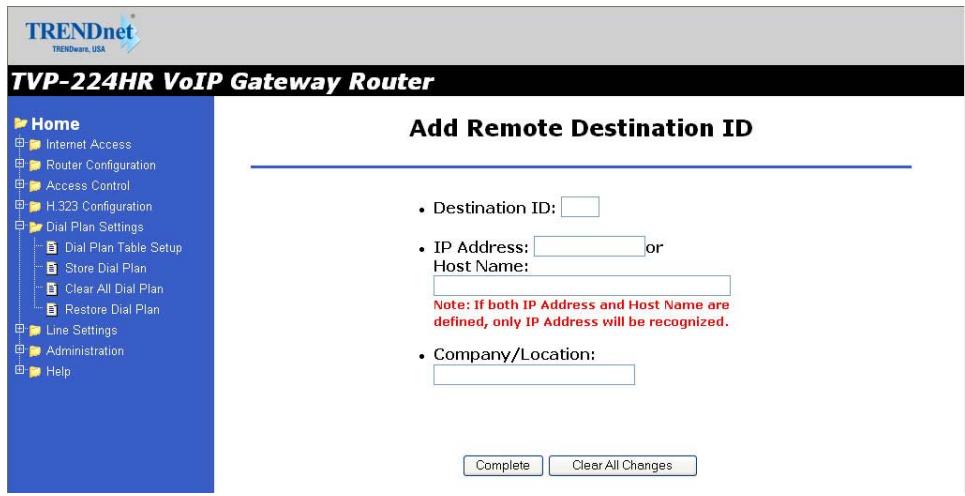
The Destination ID is either a Remote Destination IP (or Hostname but not both) or a Local Destination Channel. Please note that if a Remote Destination IP and a Hostname is specified, the Remote Destination IP takes precedence.
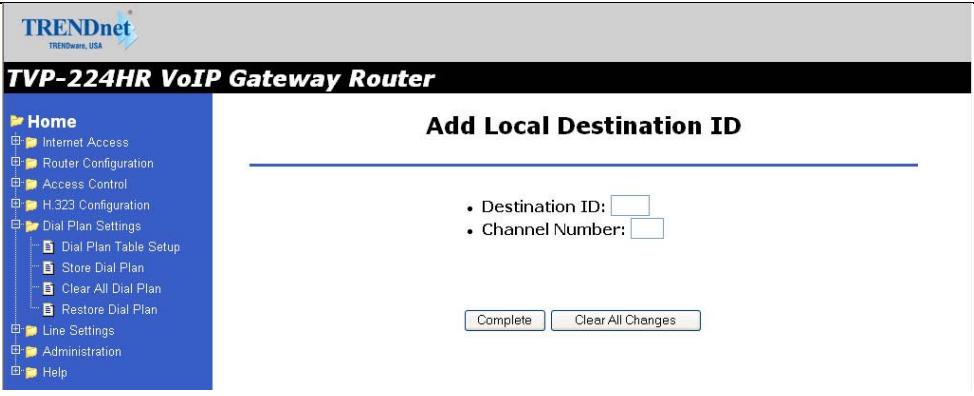
Each telephony port of the TVP-224HR must be assigned a unique destination ID. Fill out the worksheet for local destinations by designating each port a unique destination ID,
9.4 Dial in PLAR / CID
Data - Dial in PLAR / CID Screen
| DDNS Service | |
| PLAR Address | Enter PLAR Address which could be any destination telephone number already entered into the dial plan. This programs the gateway to automatically connect you to that number. This port will not be able to dial any other numbers when PLAR is used. |
| CID – Number and Name | This is a separate feature to PLAR. If you would like to have the Caller’s Identification including Number and Name forwarded to the recipient, please provide the information in the provided fields. |
| Buttons | |
| OK | On/Off |
TVP-224HR VoIP Gateway Router
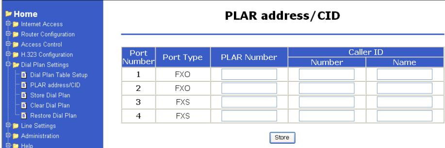
Private-line automatic ringdown (PLAR) circuits have statically configured endpoints and do not require the user dialing to connect calls. The PLAR feature provides an easy method to create a switched Voice over IP (VoIP) call without digit dialing. PLAR connections are often referred to as a "batphone" or "hotline" type of application. This is when a phone goes off-hook
and a remote phone rings without digits being dialed. This is a useful tool for customer requirements such as:
- The provision of an Off-Premises eXtension (OPX) from a private branch exchange (PBX). Connection PLAR allows remote users on Foreign Exchange Station (FXS) ports to look to a central PBX like physical extensions.
- The provision of dial-tone from a remote PBX. Many customers want to offer toll-bypass VoIP services without having the routers provide dial-tone or change their existing dialplan. This allows stations at remote sites to look like they are physically connected stations to a PBX.
Dial in PLAR Considerations and Limitations
- Dial in PLAR is a switched VoIP call. The call is setup on an as-needed basis. With connection PLAR, no bandwidth is consumed while the phone is on hook. When a phone connected to a POTS dial peer is taken off-hook, the call is automatically connected and the remote phone begins to ring.
- Dial in PLAR can work between any type or combination of Foreign Exchange Office (FXO), and/or FXS) telephony port / device.
- Dial in PLAR does not collect digits from the connected Telephony device. Once a dial plan has been entered into the ATPM, PLAR can be enabled without need to alter the dial plan. Note: All other Dial plans set for this starting port will become ineffective.
9.5 Store Dial Plan
Store Dial Plan - will store the Dial Plan from DRAM / Working Memory to Flash / Non-Volatile Storage
Always be sure to Store, the Dial Plan from working memory / DRAM to Flash Memory / Non-Volatile Storage. Storing to Non-Volatile Storage ensures that you have saved the dial plan which can then be restored on request.
Note: The Dial Plan in the Non-Volatile Storage is not the working Dial Plan. If the Gateway is turned off for what ever reason, the Dial Plan from Non-Volatile Storage is copied into the Flash / Working memory and processes phone calls accordingly
9.6 Clear Dial Plan
Clear Dial Plan - Will clear the Dial Plan from DRAM / Working memory.
DRAM – Everytime you make an entry into the Address Table, Hunt Group Table or Destination ID table, you have to Click on Complete. This only saves the plan to the working memory / DRAM. If there was a power outage or the TVP-224HR was unplugged or a system crash for what ever reason, the Dial Plan in working memory / DRAM will be lost.
9.7 Restore Dial Plan
Restore Dial Plan - Will retrieve the Dial Plan from Flash Memory / Non-Volatile Storage but erase the dial plan currently in DRAM / Working memory.
Note: To ensure your new settings are actually accepted, please check the configuration page carefully after you submit the new settings. If the new settings are not present, it probably conflicts with the old settings. or there is not enough space to store your settings.
9.8 Line Settings
Channel Status
View all settings made to each Channel (port). Simply Select the Channel (0-3) and Click on View
Codec Selection
Select the codec of your preference.
G.711 PCM 64kbps (A-law and µ -law)
G.723.1A ACELP/M-MLQ (5.3, 6.3kbps)
G.729AB CS-ACELP (8kbps)
Common Parameters
Common Parameters is found under Common Settings and allots the amount of time given to each step of the dial process.
TRENDnet
TRENDware, USA
TVP-224HR VoIP Gateway Router
Home
Internet Access
Router Configuration
图:AcessionControl
Access Control
H.323 Configuration
Dial Plan Settings
Line Settings
Channel Status
Codec Selection
Common Parameters
Channel Parameters
Channel 4.1
Telephony Ports
Administration
Help
Common Settings
Total Dial Time

First Digit Wait Time

Inter Digit Wait Time

Termination Digit

Save The Changes
Clear All Changes
Current Common Parameter Settings Are:
System Info: Total dial time = 30000ms, First digit wait = 10000ms, Interdigit wait = 5000ms, Dial term digit = None
Total Time
The total amount of time you have to enter a telephone number (Default 30000ms)
First Digit Wait Time
The amount of time you have to enter your first digit (Default 10000ms)
Inter Digit Wait Time
The amount of time you have between each digit entered (Default 5000ms)
Termination Digit
A special number which tells the gateway that you have finished entering your telephone number and that the number should be processed. (Default - none)
9.9 Channel Parameters
Allows you to set parameters associated with each port, such as transmission / receive gains and comfort noise level
9.10 Administration
Password (See Chapter 7)
- Enter Old Password
-
Enter New Password
-
Retype New Password
Telnet Access
- Select On or Off
- Click on OK
- Reboot
Interface Speed
- Select AUTO, 10 MB Full-Duplex or 100 MB Full-Duplex
- Click on OK
- Reboot
9.11 Channel Status
System status on all Channels in Table format
9.12 Help
Here you will find helpful definitions to common parameters in the TVP-224HR User Interface. In addition, from the main page in the help menu, you can link to the Trendware FTP website and download the most current User Guide and support materials ftp.trendware.com/TVP-224HR/
Chapter 10
Making Calls with TVP-224HR
This chapters show how to make phone calls from telephony devices connected to the TVP-224HR directly through or indirectly.
10.1 Configuration Examples
Default Dial Plan
Before any configuration set up, your TVP-224HR should have the following basic default information.
Network
IP : 192.168.0.1
Mask: :255.255.255.0
Gateway :0.0.0.0
Dial Plan
| No. | Hunt Group | Dest. ID | Dest. |
| 201 | 1 | 1 | 0 (local port #1) |
| 202 | 2 | 2 | 1 (local port #2) |
| 203 | 3 | 3 | 2 |
| 204 | 4 | 4 | 3 |
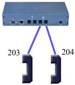
- If your TVP's two FXS ports are connected to two telephones, say port 2 and port 3 respectively, just pick up phone 203 and dial '204', phone 204 should ring.
- 204 ⇒ TVP ⇒ local port #3 ⇒))))

You may also check the LED indicators on the TVP-224HR. When it rings, the related LED should flash. After you pick up the handset, it should remain on and off when the phone is on hook.
Now let's test your TVP-224HR that is equipped with 2 FXO interfaces. Assume you have one extension line with your PBX system, say, 201 as the extension number, we connect this line to the gateway's port 0 (FXO port), then connect a telephone phone set to port 3 (for example) of the gateway.
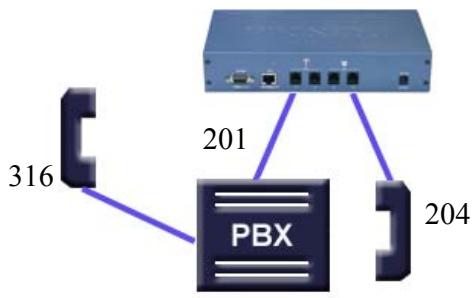
Pick up your extension handset, for example, 316 and dial '201'. After one ring, you should hear a dial tone. Now dial '203'. The telephone connected to the TVP's FXS port should ring.

If you do not hear the dial tone, please check the line impedance of your PBX. For a TVP-224HR with FXO port, please contact your PBX Supplier or System Integrator for further information
- Now let's make a call to your PBX extension. Pick up the handset connected to the FXS port and dial '201', you should hear a dial tone (This means that TVP-224HR picks up the line connected to your PBX). Then dial '316', your extension handset should ring right away.

This guide only uses the default values. Once you are familiar with the dial plan set up, you may design your own dial plan.
10.2 Making a call with TVP-224HR FXS Port
TVP-224HR has two FXS ports. An FXS port can connect to an analogue phone directly, and a FXO port can connect to a PBX system or CO line.
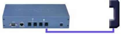
Connection: Analogue telephone set connects to FXS port
Operation:
- Pick up this analogue telephone set. You should be able to hear the dial tone provided by the TVP-224HR.
- The corresponding green LED will light up when the telephone set is picked up. For Example: If the telephone set is connected to the second port of FXS. When you pick up the telephone set, the second green LED will light up.
- We can dial the desired destination phone number at the telephone set. If the desired destination phone number is legal, the TVP-224HR will play two quick address ack tones, Du Du, to destination. If the desired destination phone number is illegal, the TVP-224HR will play three out of service tones, please check the dial plan and your desired destination phone number.
10.3 Making a call with TVP-224HR FXO Port
Connection: Analogue PBX connects to FXO port
Operation:
- Pick up this analogue telephone set, you can hear the PBX dial tone provided by the PBX system. In some cases, you have to dial a specific number to get the connection between telephone set and PBX.
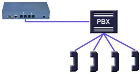
- Dial the extension number for the gateway as provided by the PBX for the TVP-224HR FXO port.
- When the TVP-224HR is connected, the corresponding green LED will be illuminated. For Example: If the telephone set is connected to the second FXO port, the second LED will be green.
- We can dial the desired destination phone number on the telephone set. If the desired destination phone number is legal, the TVP-224HR will play two quick sounds, "Du Du", to destination. If the desired destination phone number is illegal, the TVP-224HR will play three out of service tones, please check the dial plan and your desired destination phone number.
10.4 Web Browser Sample Dial Plan
This section describes how to use a web browser to build a dial plan in the VoIP Gateway. We suggest the following:
Draw an application diagram to illustrate / clarify application including:
- Local gateway: IP setup
- Local gateway: local telephone number setup
- Local gateway: remote gateway IP & remote telephone number setup
Note: The Diagram below of Gateway A & B could be any combination of either the TVP-224HR (connected to switch by WAN port) or the TVP-221H (Connected by LAN port). The switch that joins these two gateways serves the purpose of initial lab configuration. Under this configuration, both GW must be in the same IP segment. Once the dial plans have been entered and tested, the switch would be replaced by the public internet and the gateways would then have to be updated with the field application Internet Access Settings (eg. Public IP Address, Subnet Mask and Gateway IP Address). In addition, all remote destinations in the dial plan must be updated with the actual application / field IP Addresses.
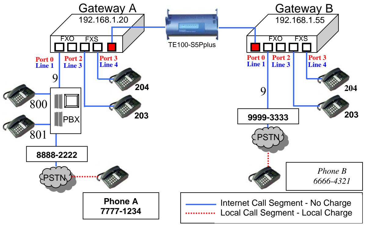

This diagram serves the purpose of illustrating the possible analog phone / PBX / PSTN integration / applications of the Gateway.
However, disconnect cadence provided by your phone company for your PSTN line and disconnect cadence provided by your PBX may require additional matching with the gateway. This will require the assistance of your PBX supplier and/or Systems Integrator. Please also see User's Guide for additional information.
Scenario description: Two gateways connected by a switch.
There are two gateways connected by a switch. They are generically labeled "Gateway" but could be any combination of either the TVP-224HR (connected to switch by WAN port) or TVP-221H (Connected by LAN port). Theoretically, GW A is
in Taiwan (Local Area Code have 2 digits) and GW B is in the US (Local Area Codes have 3 digits).
Gateway A, 4 ports, is configured as follows:
- Gateway A IP: 192.168.1.20, mask IP: 255.255.255.0, gateway IP 0.0.0.0 (virtual IP)
- FXS Port 2 has a telephone set connected, its phone number is "203"
- FXS Port 3 has a telephone set connected, its phone number is "204"
- FXO Port 0 is connected to PBX. There are two telephone sets connected to the PBX. Their extension numbers are "800" and "801".
- FXO Port 0 is registered as number "9" and it is connected to PBX
- PBX has an external line to PSTN. Dialoging "9" connects you PBX, where "9" is dialed to connect to PSTN.
- The PSTN number to reach the PBX is "8888-2222".
- Telephone A's number is "7777-1234" and belongs to the local PSTN
Gateway B, 4 ports, is configured as follows:
- Gateway B IP: 192.168.1.55, mask IP: 255.255.255.0, gateway IP 0.0.0.0 (virtual IP)
- FXS Port 2 has an analog telephone set connected, its phone number is "203"
- FXS Port 3 has an analog telephone set connected, its phone number is "204"
- FXO Port 0 is registered as number "9". Dialing "9" connects you to the outside line.
- FXO Port 0 is connected to PSTN line "9999-3333".
- Telephone B's number is "6666-4321" and belongs to the local PSTN.
Gateway A - IP setup:
- Navigate to Internet Access / Fixed IP Menu
- Type in IP Address: 192.168.1.20, Subnet Mask: 255.255.255.0 and Default IP Gateway Address: 0.0.0.0 in the related fields.
- Click on "Save"
- Click on "Reboot"
- Navigate to Internet Access / Fixed IP Menu.
- Type in IP Address: 192.168.1.55, Subnet Mask: 255.255.255.0 and Default IP Gateway Address: 0.0.0.0 in the related fields.
- Click on "Save"
- Click on "Reboot"
Gateway A: Dial Plan Setup
FXS Ports to Analog Phones - Gateway A has two phones on the FXS ports.
Telephone number 203 on Port 2 and 204 on Port 3. These numbers are part of the default dial plan and do not have to be entered. We can skip the local Dial Plan setup including Telephone Address, hunt group and destination for phones 203 and 204.
How to Enter the Dial Plan
The Dial plan consists of three tables that include the Telephone Table, Hunt Group (eg. Customer Service may have multiple phones that the GW must search through for an open line), and Destination Table (Both Local and Remote). The dial plan has to be entered into all Gateways so that the local gateway knows how to process calls, sending them to its local ports or to remote gateways for further processing.
The following screen shots show an example for entering a dial plan for a single number. This example should give you the necessary insight as to how to enter the rest of the Dial Plan. If you still have difficulty understanding the dial plan and entering data, please reference the User Manual for more examples.
- From the Navigation Menu on the left side, Select Dial Plan Table Setup
- From the window, please Select
- The following window will appear. Please Enter Data as shown
- Click on Ok
TVP-224HR VoIP Gateway Router
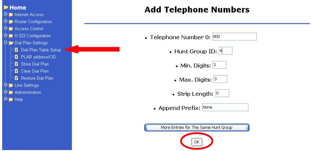
- From the Navigation Menu on the left side, Select Dial Plan Table Setup
- From the window, please Select
-
The following window will appear. Please Enter Data as shown
-
Click on Ok
TVP-224HR VoIP Gateway Router
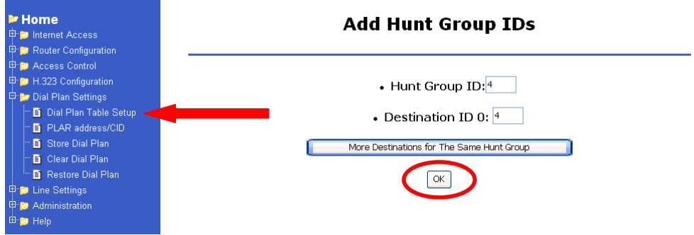
- From the Navigation Menu on the left side, Select Dial Plan Table Setup
- From the window, please Select
- The following window will appear. Please Enter Data as shown
- Click on Ok
TVP-224HR VoIP Gateway Router
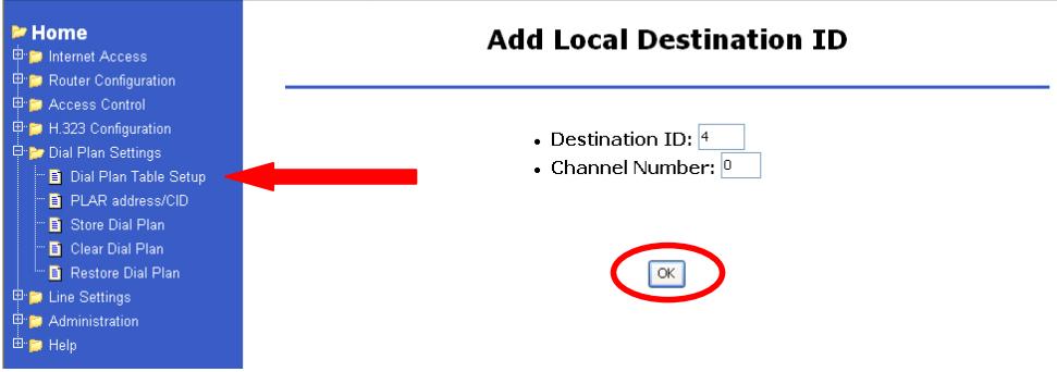
- Continue entering the Gateway A Dial Plan as laid out in the tables below (Telephone Table, Hunt Group Table and Destination Table) following the above procedures.
- After you have entered the Dial Plan, make sure you Store Dial Plan to flash memory. From the Navigation Bar on the left side, Click on Store Dial Plan
- The following screen will appear on the right side. Click on YES
TVP-224HR VoIP Gateway Router
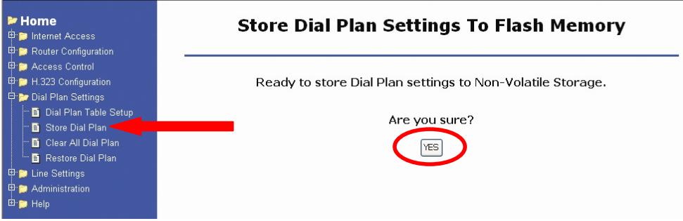
Gateway B: Dial Plan Setup
- Enter Gateway B Dial Plan into Gateway B as shown in the tables below (Telephone Table, Hunt Group Table and Destination Table) following the above procedures.
- After entering all the information listed in the tables below, DO NOT navigate away from Dial Plan Settings. Click Store Dial Plan, and click YES to save your dial plan to Flash Memory.
Gateway A and Gateway B Dial Plan Tables
Gateway A - Telephone Number Table
| Phone # | Hunt Group ID | Min. Digits | Max. Digits | Prefix strip | Prefix Address | Function | Comment |
| 203 | 2 | 3 | 3 | 3 | None | Dialing “203” calls phone on FXS Port 2 | |
| 204 | 3 | 3 | 3 | 3 | None | Dialing “204” calls phone on FXS Port | |
| 3 | |||||||
| 800 | 4 | 3 | 3 | 0 | None | Dialing “800” calls PBX on FXO Port 0, which then dials “800”. | This is an example only. Please substitute your ext# on PBX if applicable |
| 801 | 5 | 3 | 3 | 0 | None | Dialing “801” calls PBX on FXO Port 0, which then dials “801”. | This is an example only. Please substitute your ext# on PBX if applicable |
| 9 | 6 | 1 | 1 | 0 | None | Dialing “9” from local phone on FXS Port connects you FXO Port 0 PBX, where “9” is dialed for outside line. | For PBX on FXO use only |
| 01 | 7 | 10 | 12 | 2 | “9” | After receiving “01” + 8 to 10 digits (2 Digit Taiwan Area Code) from GW B, “01” is stripped, prefix address “9” is dialed to PBX on FXO Port 0 for outside line and then, remaining 8 to 10 digits are dialed. | For PBX on FXO use only |
| 22 | 22 | 5 | 5 | 2 | None | “22” is stripped and remaining 3 digits are sent to GW B. | Remote Zone # used to make calls to remote GW B FXS (Internal Ext) |
| 02 | 22 | 10 | 13 | 0 | None | “02” + 8 to 11 digits (3 Digit US Area Code) are sent to GW B. | Remote Zone # used to make calls to remote GW B FXO (External - PBX to PSTN) |
Gateway A - Hunt Group Table
| Hunt Group ID | Hunt Type | # of Dest ID(s) | Dest. ID(s) |
| 2 | 2 | 1 | 2 |
| 3 | 2 | 1 | 3 |
| 4 | 2 | 1 | 4 |
| 5 | 2 | 1 | 4 |
| 6 | 2 | 1 | 4 |
| 7 | 2 | 1 | 4 |
| 22 | 2 | 1 | 22 |
Gateway A - Destination Table
| Dest ID | Mode | Destination |
| 2 | Local | Port = 2 |
| 3 | Local | Port = 3 |
| 4 | Local | Port = 0 |
| 22 | Remote | Dest = 192.168.1.55/1720 TCP |

The above destination table has both local destinations and remote destinations. When the gateways are taken out of this initial testing environment, and implemented in the field, the internet access settings will have to be updated. In addition, the above remote destination IP will have to be updated to the field IP address.
Gateway B - Telephone Number Table
| Phone # | Hunt Group ID | Min. Digits | Max. Digits | Prefix strip | Prefix Address | Function | Comment |
| 203 | 2 | 3 | 3 | 3 | None | Dialing “203” calls phone on Port 2 | |
| 204 | 3 | 3 | 3 | 3 | None | Dialing “204” calls phone on Port 2 | |
| 9 | 4 | 1 | 1 | 1 | None | Dialing “9” from local phone on FXS Port gets you a dial tone on FXO Port 0 for outside line. | Assumes that Telephone line is attached to Port 0 / Line 1 |
| 02 | 5 | 10 | 13 | 2 | None | “02” is stripped, and the remaining 8 to 11 digits (3 Digit US Area Code) are dialed out on Port 0 to PSTN. | Assumes that Telephone line is attached to Port 0 / Line 1 |
| 11 | 11 | 5 | 5 | 2 | None | “11” is stripped and remaining 3 digits are sent to GW A. | Remote Zone # used to make calls to remote GW A FXS (Internal Ext) |
| 01 | 11 | 10 | 12 | 0 | None | “01” + 8 to 10 digits (2 Digit Taiwan Area Code) are sent to GW B. | Remote Zone # used to make calls to remote GW A FXO (External - to PSTN) |
Gateway B - Hunt Group Table
| Hunt Group ID | Hunt Type | # of Dest ID(s) | Dest. ID(s) |
| 2 | 2 | 1 | 2 |
| 3 | 2 | 1 | 3 |
| 4 | 2 | 1 | 4 |
| 5 | 2 | 1 | 4 |
| 11 | 2 | 1 | 11 |
Gateway B - Destination table
| Dest ID | Mode | Destination |
| 2 | Local | Port = 2 |
| 3 | Local | Port = 3 |
| 4 | Local | Port = 0 |
| 11 | H.323 | Dest = 192.168.1.20/1720 TCP |
①
The above destination table has both local destinations and remote destinations. When the gateways are taken out of this initial testing environment, and implemented in the field, the internet access settings will have to be updated. Likewise, the above remote destination IP will have to be updated to the field Destination IP address.
10.5 Making a call between Gateway A and Gateway B
Case 1: Gateway Phone to Gateway Phone
| Gateway B phone 203 calls Gateway A phone 203 | ||
| Caller Operation at GW B | Equipment Operation | Receiver Operation at GW A |
| Pick up phone 203 (204) | 1. GW dial tone is heard. | |
TVP-224HR User's Guide
| 2. GW B Line 3 LED “ON” | ||
| Dial 11203 (11204, 11800, 11801) | 1. Du Du is heard 2. VoIP call processing | |
| Ring back tone is heard | 1. GW A Line 3 LED “ON” | Phone 203 rings |
| Pick up phone 203 | ||
| VoIP Conversation | VoIP Conversation |
The above process is the same for Gateway B phone 203 and 204 calls to Gateway A phone 201, 800 and 801.
Case 2: Gateway Phone to PSTN Phone
| Gateway B phone 203 calls to PSTN phone A number 7777-1234 | ||
| Caller Operation at GW B | Equipment Operation | Receiver Operation at GW A |
| Pick up phone 203 (204) on GW B | 1. GW dial tone is heard. 2. GW B Line 3 LED “ON” | |
| Dial 01-7777-1234 | 1. Du Du is heard 2. VoIP call processing | |
| Ring back tone is heard | 1. GW A Line 1 LED “ON” 2. GW A is connected to PSTN | |
| Ring back tone is heard | 1. PSTN call processing | Phone 7777-1234 is ringing |
| Receiver on 7777-1234 picks up | ||
| VoIP Conversation | VoIP Conversation | |
The above dialing process is the same for phones 203, 204 to any GW A local PSTN phone number.
Case 3: PSTN Phone to Gateway Phone
| Phone A, number 7777-1234 calling Gateway B phone 203 | ||
| Caller Operation at Phone A | Equipment Operation | Receiver Operation at GW B phone 203 |
| Pick up phone A | 1. PSTN dial tone is heard. | |
| Dial 8888-2222 | 1. Call being processed2. PBX plays voice greeting | |
| Dial 22203 (22204) | 1. Du Du tone is heard2. VoIP call processing | |
| Ring back tone is heard | ||
| 1. GW A Line 1 LED “ON” | Phone 203 is ringing | |
| 1. GW B Line 3 LED “ON” | Receiver Picks up phone 203 | |
| VoIP Conversation | VoIP Conversation | |
The above dialing process is the same for any calls made from GW A local PSTN to remote phone numbers 203 & 204.

Case 1-3 Sample Dial Plans show the possible analog phone / PBX / PSTN integration / applications of the Gateway. Disconnect cadence provided by your phone company for your PSTN line and disconnect cadence provided by your PBX may require additional matching with the gateway. This will require the assistance of your PBX supplier and / or Systems Integrator. Please also see User's Guide for additional information.
10.6 VoIP in a Dynamic IP environment
Internet Access
The previous section dealt with the TVP-222H in and its configuration in a static IP environment. The following section will address the issue of Dynamic IP and the TVP-224HR deployment in such an environment. This section we will show you how to connect two TVP-224HR in a dynamic IP address environment and configure PPPoE, DHCP, and DDNS clients.
10.7 PPPoE, DHCP, and DDNS clients:
In addition to fixed IP, the TVP-224HR can be configured to use PPPoE or DHCP clients. With PPPoE and DHCP, you will under most circumstances be assigned a Dynamic IP. In order for other people and devices to locate you, they will need to be pointed to your dynamic IP. Therefore, it is necessary that you register with a DDNS (Note: www.dyndns.org is currently the only service supported). Once you have registered an account, and have configured the DDNS client in the TVP-224HR, the TVP-224HR will automatically notify DynDNS of your changing IP Address. DynDNS will in turn, map your Dynamic IP to your registered Domain Name. See Chapter 6, DDNS section for more information.
The first time you connect to the TVP-224HR for configuration, you will need to connect to it under the same LAN segment to set the DHCP or PPPoE client. To configure the TVP-224HR, insert one end of an Ethernet cable into one of the 4 RJ45 LAN ports on the rear panel of the TVP-224HR and the other end directly to your PC Terminal. By default, the TVP-224HR's DHCP server is enabled. Make sure your computer is DHCP client enabled (See Chapter 4, PC Configuration). If you choose to assign a Fixed IP to your PC, make sure that you do not assign a IP that that is already allocated to the DHCP server for DHCP clients. The TVP-224HR supports auto MDIX so Cat 5 cable will be sufficient.
Case 4: Gateway Prefix-Simplified Gateway Phone to Gateway Phone
After these dial plans are added, users on Site A are able to dial “22 + extension number” to connect to users on site B for free VoIP telephony. Users on Site B are able to call phones on Site A for free VoIP telephony by dialing “11 + extension number”. (Note: There is a Max digit (5) limitation on the dial plan which allows the TVP-224HR to differentiate with potential PSTN numbers that may start with 11 or 22 but because they exceed 5 digits, they would be handled differently).
The benefits of this dial plan are:
- Simplified setup
- VoIP (Free calls to remote site extension)
- Simplified dialing ensures easy, direct access to remote extensions.
- Simplified dialing makes remote offices and branches feel like local extensions.
Two TVP-224HR Gateways (Both Gateways are set up with default settings)
- TVP-224HR A, located site A
- TVP-224HR B, located on site B.
Register DDNS name for both Dynamic IPs (See Chapter 6)
- tvp1.dyndns.org is applied for TVP-224HR on site A
- tsp2.dyndns.org is applied for TVP-224HR on site B
Clients used on this topology :
- TVP-224HR on site A has PPPoE, and DDNS clients enabled
- TVP-224HR on site B has DHCP, and DDNS clients enabled.
Network topology illustrated as follows
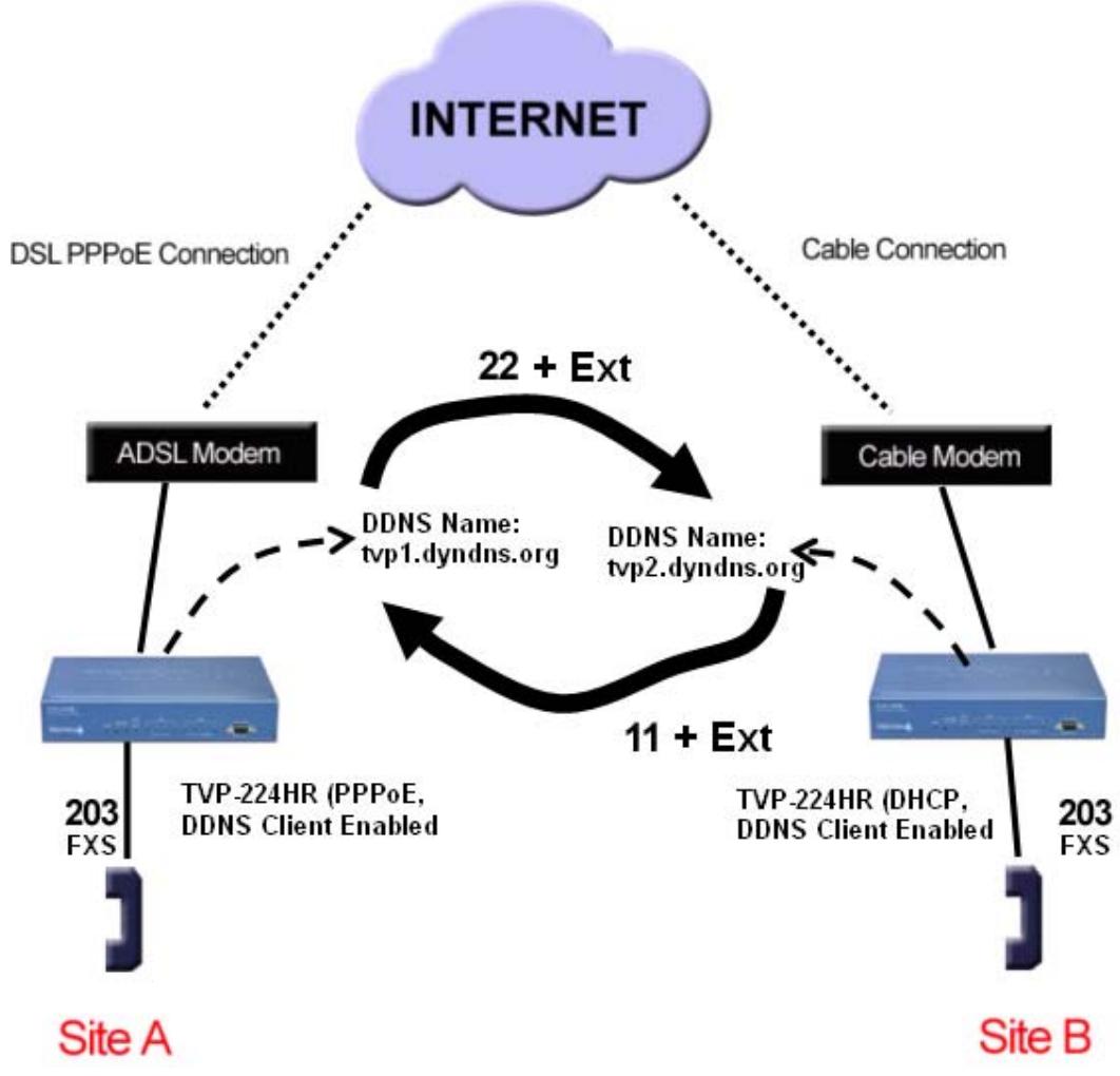
| TVP-221HTVP-224HR configuration (ADSL PPPoE connection) on site A | |
| Web Configuration | Telnet / Console |
| Local (from a PC in same Segment) From the Logon to the Web Configuration by Open opening your browser 1. Enter 192.168.0.1 2. You will be prompted for Username and Password. DefaultUsername and Password are “admin” and “123” respectively. | Console Connect RS-232 to TVP-224HR and PC Open Hyper Terminal Input parameters: Baud rate 19,200 Number of data bit 8 Parity check None Number of stop bit 1 Flow control None Enter “123” |
| Local Telnet (from a PC in same Segment) From Windows command prompt Enter “telnet 192.168.0.1” EnterUsername “admin” Enter “123” | |
| Web Configuration of Internet Access Internet Access / PPPoE 1. Select “Yes” to enable PPPoE function 2. Enter username and password provided by your ISP 3. Click on “Save” Router Configuration / Dynamic DNS 4. Select “On” 5. Enter Server Name, Host Name, User Name, Password 6. Click on “Save” | net set pppoe on net set pppoe user [name] [password] net set ddns on net set ddns add [server_name] [host_name] [user_name] [password] (eg. dyndns.org tsp1 username1 password1) net store |
Once Internet Access is setup, you could choose to reboot the TVP-224HR, and then use a PC in the same segment and with a web browser, access theTVP-224HR:
If using the Router's DHCP Server, make sure the routers DHCP Server is on and that the configuring PC is DHCP Client enabled.
If you would like your PC to have a Fixed IP, Make sure that the IP does not conflict with the range of IP's allocated by the TVP-224HR's DHCP Server.
If you are trying to access the TVP-224HR from a PC in the same segment as the TVP-224HR (LAN), Open your browser and enter
- Enter 192.168.0.1
If you would like to access the TVP-221H from the WAN side, from a remote PC with Internet Access:
- Enter tsp2.dyndns.org
You will be prompted for username and Password. DefaultUsername and Password are "admin" and "123" respectively.
You could then continue as below:
Web Configuration of Dial Plan
Dial Plan Settings / Dial plan Table Setup
-
Select "Add" and "Telephone
-
Enter following fields
a. Telephone Number:22
b. Hunt Group ID: 22
c. Min. Digits: 2
d. Max.Digits: 5
e. Strip Length: 2
f. Append Prefix: none
- Click on "OK"
Dial Plan Settings / Dial plan Table Setup
- Select "Add" and "HuntGroup"
From the local connection, you could continue on setting up the dial plan. However you could choose to reboot,
Enter "net reset"
Connect your PC directly to your TVP-224HR making sure they are in the same LAN segment. From the windows command prompt:
Enter "telnet 192.168.0.1"
Or from a remote computer
Enter "telnet
tvp1.dyndns.org"
You would then continue as below:
atpm req
atpm aadd 22 25 22 2
atpm hadd 22 2 22
- Enter following fields
a. Hunt Group ID: 22
b. Destination ID 0: 22
- Click on "OK"
Dial Plan Settings / Dial plan Table Setup
- Select "Add" and "DestinationID"
- Enter the following fields
a. Destination ID: 22
b. Hostname (or IP address)
tvp2.dyndns.org
c. Click on "OK"
Dial Plan Settings / Store Dial Plan
- Click on "Yes"
atpm dad 22 dns tvp2.dyndns.org
atpm done
atpm store
Changes to network settings require rebooting to take effect. Changes to the Dial Plan do not and will take effect as soon as they are stored.
Caution: If you do not store the dial plan, it will be lost when you reboot.
Note: After changing the Internet Access settings, you will be required to use 192.168.0.1 to gain access from the local LAN segment or tvp1.dyndns.org, to gain remote access via the Internet.
TVP-221HTVP-224HR configuration (cable connection) on site B
Web Configuration
Local (from a PC in same Segment)
Open your browser
- Enter 192.168.0.1
- You will be prompted for username and Password. DefaultUsername and Password are "admin" and "123" respectively.
Login
From the Logon to the Web
Configuration by opening your browser
- Enter 192.168.0.1
- You will be prompted for
Username and Password.
Telnet / Console
Console
Connect RS-232 to TVP-224HR and PC
Open Hyper Terminal
Input parameters:
Baud rate 19,200
Number of data bit 8
Parity check None
Number of stop bit 1
Flow control None
Enter "123"
Default username and Password are "admin" and "123" respectively.
Web Configuration of Internet Access
Internet Access / DHCP Client
- Select "Yes"
- Click on "Save"
Router Configuration / Dynamic DNS
- Select "Enable"
- Enter Server Name, Host Name, User Name, Password
- Click on "Save"
Once Internet Access is setup, you could choose to reboot the TVP-224HR, and then use a PC in the same segment and with a web browser, access theTVP-224HR:
If using the Router's DHCP Server, make sure the routers DHCP Server is on and that the configuring PC is DHCP Client enabled.
If you would like your PC to have a Fixed IP, Make sure that the IP does not conflict with the range of IP's allocated by the TVP-224HR's DHCP Server.
If you are trying to access the TVP-224HR from a PC in the same segment as the TVP-224HR (LAN), Open your browser and enter
a. Enter 192.168.0.1
If you would like to access the TVP221H from the WAN side, from a remote PC with Internet Access:
b. Enter tsp1.dyndns.org
You will be prompted for username and Password. DefaultUsername and Password are "admin" and "123" respectively.
You could then continue as below:
Web Configuration of Dial Plan
Telnet (from a PC in same Segment)
From Windows command prompt Enter "telnet 192.168.0.1"
EnterUsername“admin” Enter“123”
From Windows command prompt
Enter "telnet 192.168.0.1"
EnterUsername "admin"
Enter "123"
net set dhcp on.
net set ddns on
net set ddns add dyndns tsp2
username2 password2
net store
From the local connection, you could continue on setting up the dial plan. However you could choose to reboot,
Enter "net reset"
Connect a PC directly to your TVP-224HR making sure they are in the same LAN segment. From the windows command prompt:
Enter "telnet 192.168.0.1"
Or from a remote computer
Enter "telnet tsp2.dyndns.org"
EnterUsername "admin"
Enter "123"
You would then continue as below:
Dial Plan Settings / Dialplan Table Setup
-
Select "Add" and "Telephone
-
Enter following fields
a. Telephone Number: 11
b. Hunt Group ID: 11
c. Min. Digits: 2
d. Max. Digits: 5
e. Strip Length: 2
f. Append Prefix: none
- Click on "OK"
Dial Plan Settings / Dialplan Table Setup
-
Select "Add" and "HuntGroup"
-
Enter following fields
a. Hunt Group ID: 11
b. Destination ID: 11
- Click on "OK"
Dial Plan Settings / Dialplan Table Setup
-
Select "Add" and "DestinationID"
-
Enter the following fields
c. Destination ID: 11
d. Hostname (or IP address)
tvp1.dyndns.org
e. Click on "Ok"
Dial Plan Settings / Store Dial Plan
- Click on "Store"
atpm req
atpm aadd 1125112
atpm hadd 11 2 11
atpm dad 11 dns tvp1.dyndns.org
atpm done
atpm store
Changes to network settings require rebooting to take effect. Changes to the Dial Plan do not and will take effect as soon as they are stored.
Caution: If you do not store the dial plan, it will be lost when you reboot.
Note: After changing the default IP address, you will be required to use the new IP Address (hostname), in this example tsp2.dyndns.org, to gain access to the TVP-224HR via web browser user interface or Telnet.
10.8 Dial in PLAR (Hotline) - TVP-224HR / TVP-224HR
Trendware VoIP Gateways are capable of automatically calling or forwarding an incoming call from the Internet or PSTN line onward to another remote destination.
The following three examples illustrate these topographies:
- FXS to FXO PLAR
- FXO to FXS PLAR
- FXO to FXO PLAR
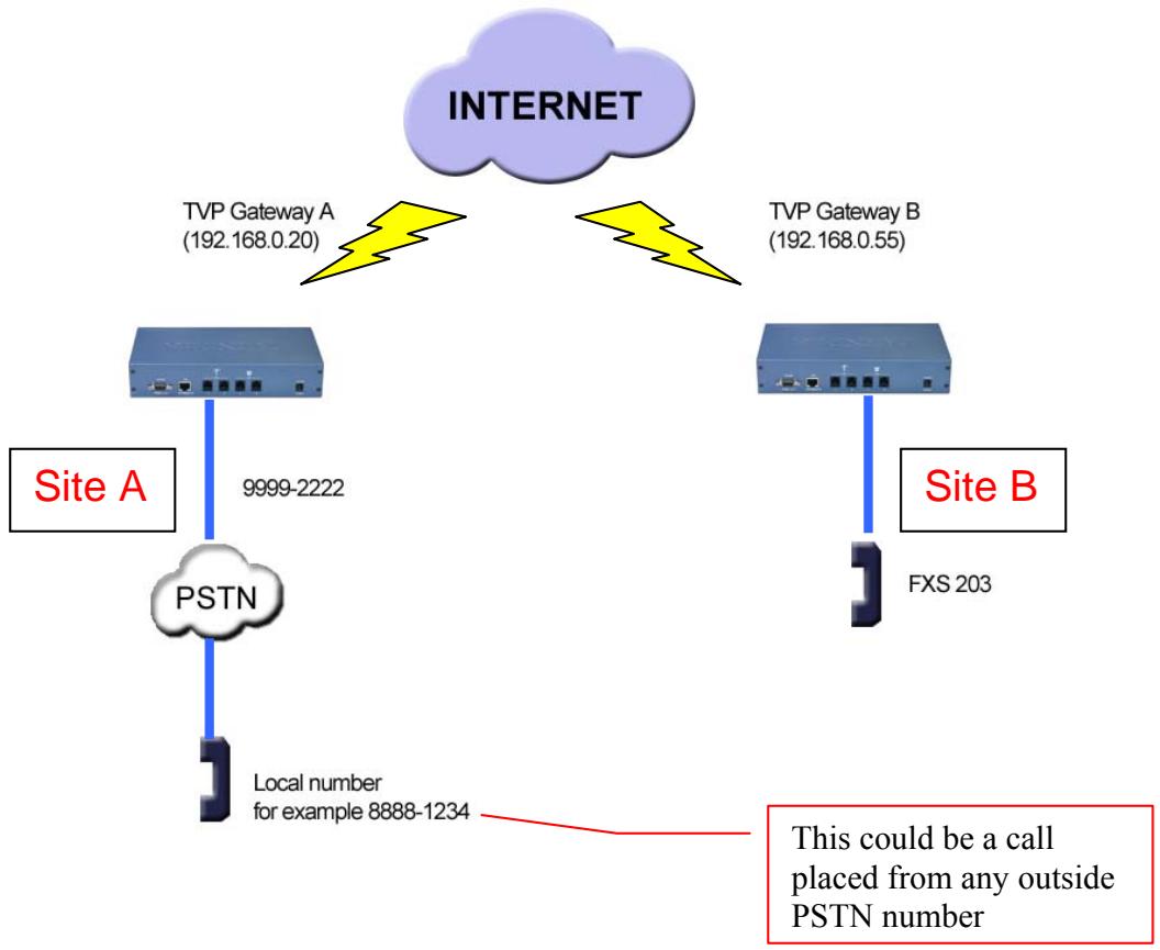
Case 5: PLAR (Hotline) FXO to FXS example
Case Scenario:
Outside PSTN caller near Site A wants calls automatically forwarded to extension 203 on Site B.
Definition - PLAR - Private Line Auto Ring - Bat phone / Hotline which allows you to pick up phone and automatically be connected to pre-determined remote destination.
Solution: Set up hotline (PLAR) on TVP Gateway on Site A to TVP Gateway on Site B. This uses existing default local dial plan with the addition of a remote destination zone number.
Usage: PSTN Caller near Site A picks up phone 8888-1234 and dials PSTN number 9999-2222 which is connected to Site A TVP Gateway FXO port 201. TVP Gateway A will automatically forward the call via internet to TVP Gateway B FXS phone 203.
| Site A TVP Gateway configuration - FXO to FXS PLAR | |
| Web Configuration | Telnet / Console |
| Login in to Site A TVP Gateway Logon to the Web Configuration by opening your browser 1. Enter Wan IP xxx.xxx.xxx Or if you are on the LAN, 192.168.0.20 2. You will be prompted forUsername and Password. DefaultUsername and Password are “admin” and “123” respectively. | From Console EnterUsername “admin” Enter Password “123” or Windows command prompt Enter “telnet xxx.xxx.xxx.xxx” EnterUsername “admin” Enter Password “123” atpm req atpm aadd 22 5 5 22 2 |
| Web Configuration of Dial Plan Dial Plan Settings / Dial Plan Table Setup 3. Select “Add” and “Telephone 4. Enter following fields a. Telephone Number: 22 b. Hunt Group ID: 22 c. Min. Digits: 5 d. Max. Digits: 5 e. Strip Length: 2 f. Append Prefix: none 5. Click on OK Dial Plan Settings / Dial Plan Table Setup 6. Select “Add” and “HuntGroup” 7. Enter following fields a. Hunt Group ID: 22 b. Destination ID 0: 22 8. Click on OK Dial Plan Settings / Dial Plan Table Setup 9. Select “Add” and “DestinationID” 10. Enter the following fields a. Destination ID: 22 b. Hostname (or IP address) 192.168.0.55 c. Click on OK Dial Plan Settings / Dial in PLAR/CID 11. Enter 22203 into the PLAR Address Field 12. Click on OK Dial Plan Settings / Store Dial Plan 13. Click on Yes | Lines 3-10 creates a zone number (a number that tells the ATPM to forward to a remote destination) address entry in TVP GW A for TVP GW B atpm hadd 22 2 22 atpm dadd 22 h323 192.168.0.55 atpm done atpm store set tcid 0 dial_in plar 22203 config activate config store |
| Lines 11-13 Setup the hotline (PLAR) from TVP Gateway A to TVP Gateway B | |
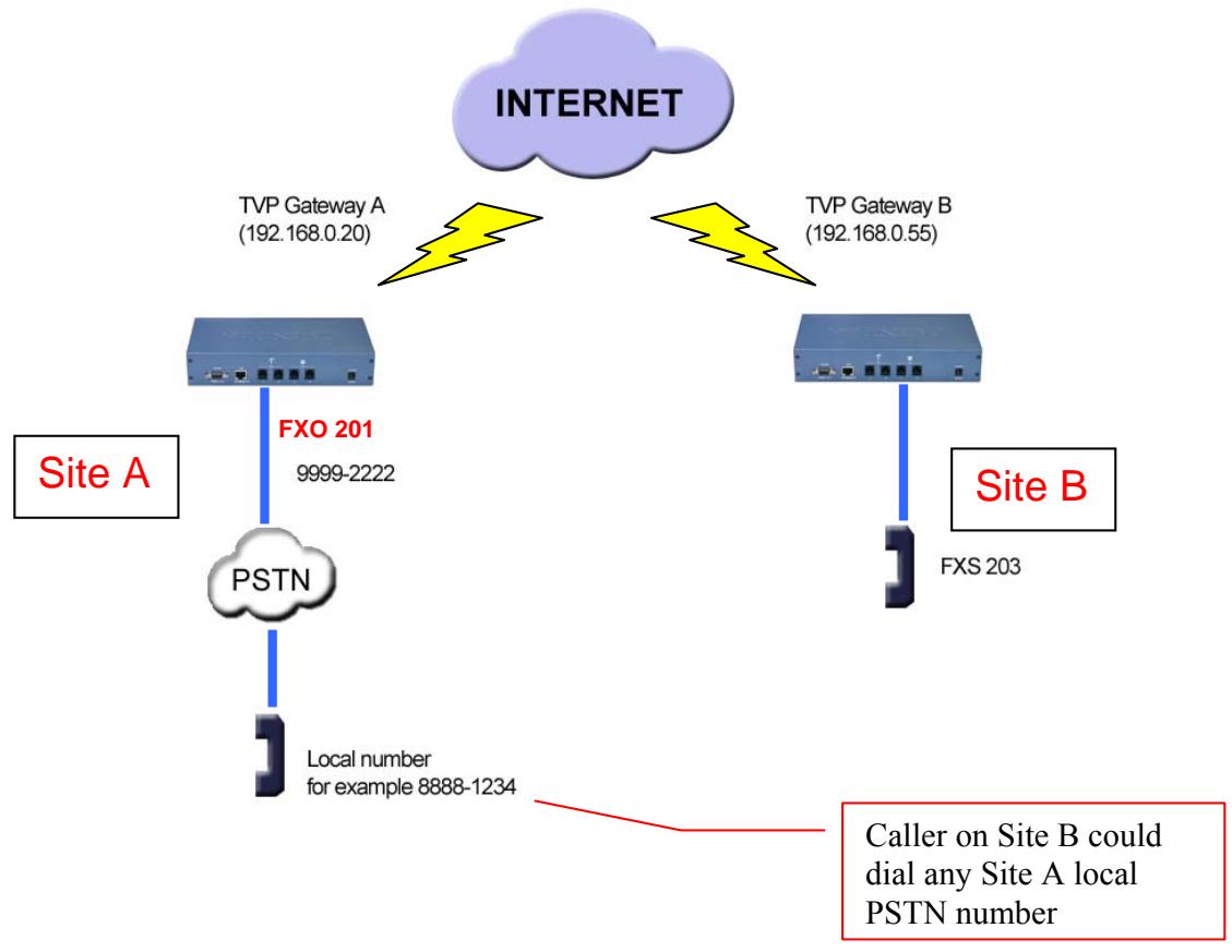
Case 6: PLAR (Hotline) FXS to FXO example
Case Scenario:
Caller on Site B FXS 203 wants to be able to pick up phone and immediately have dial tone to Site A local PSTN.
Solution: Set up hotline (PLAR) on TVP Gateway on Site B to TVP Gateway on Site A. This uses existing default local dial plan with the addition of a remote destination zone number.
Definition - PLAR - Private Line Auto Ring - Bat phone / Hotline which allows you to pick up phone and automatically be connected to pre-determined remote destination.
Usage: Caller on Site B picks up FXS 203 phone and TVP Gateway B automatically connects to TVP Gateway A FXO 201 which is connected to PSTN line 9999-2222. Caller will hear PSTN dial tone on Site A and can then call any number on local PSTN.
| Site B TVP Gateway Configuration - FXS to FXO PLAR | |
| Web Configuration | Telnet / Console |
| Login to Site A TVP Gateway 1. Logon to the Web Configuration by opening your browser 2. Enter 192.168.0.55 3. You will be prompted for username and Password. DefaultUsername and Password are “admin” and “123” respectively. | From Console EnterUsername“admin” EnterPassword“123” or from Windows command prompt Enter“telnet 192.168.0.55” EnterUsername“admin” EnterPassword“123” atpm req atpm aadd 11 5 5 11 2 |
| Web Configuration of Dial Plan Dial Plan Settings / Dial Plan Table Setup 4. Select “Add” and “Telephone 5. Enter following fields a. Telephone Number :11 b. Hunt Group ID: 11 c. Min. Digits: 5 d. Max. Digits: 5 e. Strip Length: 2 f. Append Prefix: none | Lines 4-13 creates a zone number (a number that tells GW B to forward to a remote destination) for TVP GW A. |
| 6. Click on OK Dial Plan Settings / Dial Plan Table Setup 7. Select “Add” and “HuntGroup” 8. Enter following fields a. Hunt Group ID: 11 b. Destination ID: 11 | atpm hadd 11 2 11 |
| 9. Click on OK Dial Plan Settings / Dial Plan Table Setup 10. Select “Add” and “DestinationID” 11. Enter the following fields a. Destination ID: 11 b. Hostname (or IP address) 192.168.0.20 c. Click on OK | atpm dadd 11 h323 192.168.0.20 atpm done atpm store |
| Dial Plan Settings / Dial in PLAR/CID 12. Enter 11201 in the PLAR Address Field 13. Click on OK | set tcid 0 dial_in plar 11201 config activate config store |
| Dial Plan Settings / Store Dial Plan 14. Click on Yes | |
| Lines 12-14 setup the hotline (PLAR) from TVP Gateway B to TVP Gateway A | |
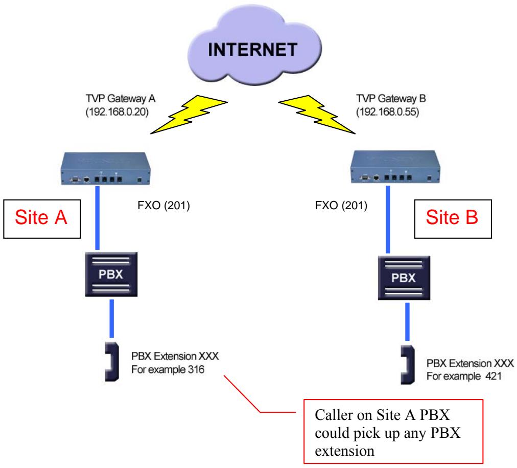
Case 7: PLAR (Hotline) FXO to FXO example
Case Scenario:
Site A PBX Extension Caller 316 wants to be able to pick up phone, dial a number and immediately have dial tone on Site B PBX, and then be able to call any Site B PBX extension.
Solution: Set up hotline (PLAR) on TVP Gateway on Site A
Usage: Caller on Site A picks up any PBX extension and dials extension 201. TVP Gateway A automatically establishes a connection with TVP Gateway B Port 0, FXO 201 to get the dial tone from PBX on site B. After getting dial tone, the caller can call any Site B PBX extension.
| Site A TVP Gateway Configuration - FXO to FXO PLAR | |
| Web Configuration | Telnet / Console |
| Login to Site A TVP Gateway 1. Logon to the Web Configuration by opening your browser Enter 192.168.0.20 2. You will be prompted for username and Password. DefaultUsername and Password are “admin” and “123” respectively. | From Console EnterUsername“admin” EnterPassword“123” or from Windows command prompt Enter“telnet 192.168.0.20” EnterUsername“admin” EnterPassword“123” atpm req atpm aadd 22 5 5 22 2 |
| Web Configuration of Dial Plan Dial Plan Settings / Dial Plan Table Setup 3. Select “Add” and “Telephone 4. Enter following fields a. Telephone Number: 22 b. Hunt Group ID: 22 c. Min. Digits: 5 d. Max. Digits: 5 e. Strip Length: 2 f. Append Prefix: none 5. Click on OK Dial Plan Settings / Dial Plan Table Setup 6. Select “Add” and “HuntGroup” 7. Enter following fields a. Hunt Group ID: 22 b. Destination ID 0: 22 8. Click on OK Dial Plan Settings / Dial Plan Table Setup 9. Select “Add” and “DestinationID” 10. Enter the following fields a. Destination ID: 22 b. Hostname (or IP address) 192.168.0.55 c. Click on OK Dial Plan Settings / Dial in PLAR/CID 11. Enter 22201 in the PLAR Address Field 12. Click on OK Dial Plan Settings / Store Dial Plan 13. Click on Yes | Liness 3-12 create an address entry for TVP Gateway B atpm hadd 22 2 22 atpm dadd 20 h323 192.168.0.55 atpm done atpm store set tcid 0 dial_in plar 22201 config activate config store |
| Lines 11-13 setup the hotline (PLAR) from TVP Gateway A to TVP Gateway B | |
Chapter 11
Telephony Connections
This section discusses the special connection consideration for various environments and situations where you can use the VoIP Gateway.
11.1 Port Configuration
VoIP Gateway supports FXS and FXO ports.
FXS (Foreign Exchange Station)
FXS provides power and ringing signals to its interfacing equipment. It is not intended for connection to the Public Switched Telephone Network. It is a station loop start operation that provides a connection to:
- A standard, single-line analog telephone system
- The line circuit of a key telephone system
- A loop start trunk circuit of a Private Branch Exchange (PBX) that normally connects to incoming Central Office circuits
FXO (Foreign Exchange Office)
FXO recognizes signals and draws current to indicate an active state. It is a trunk loop start operation that emulates a single-line telephone to:
- Central Office lines
- PBX station
There are three basic environments that the TVP-224HR can be applied to. They are described in the following sections.
Application 1: Special FXS Connections
The following diagram illustrates two different types of connections. The SITE A FXS Connection shows the normal connection between a gateway and telephone set (POTS) or FAX machine. The other type of FXS connection is shown on SITE B, on the right hand side. The Connection between the gateway and PBX has a special CO trunk interface card. The telephone sets connected to PBX can be either POTS or digital telephone depending upon the PBX capability.

Application 2: FXO Connections
Application 2 has three possible connections. One Site A, the FXS connection to analog devices is normal and is identical to connections mentioned in Application 1. On Site B, the connection between PSTN and PBX is also a normal connection. The last connection is between PBX and the gateway which uses the internal analogue lines of the PBX. In this case, the FXO port has to be used.
Note: If a digital PBX is used, an analog terminal adapter is needed to provide an analog interface to the FXO port. Please consult with your PBX supplier.
In this application, the caller on Site A, can make a call using a device connected to a FXS port on the Site A gateway. The call will be routed to the Site B Gateway, through a FXO port and passed on to the PBX system. The PBX system will then forward the call to the dedicated terminal / extension.
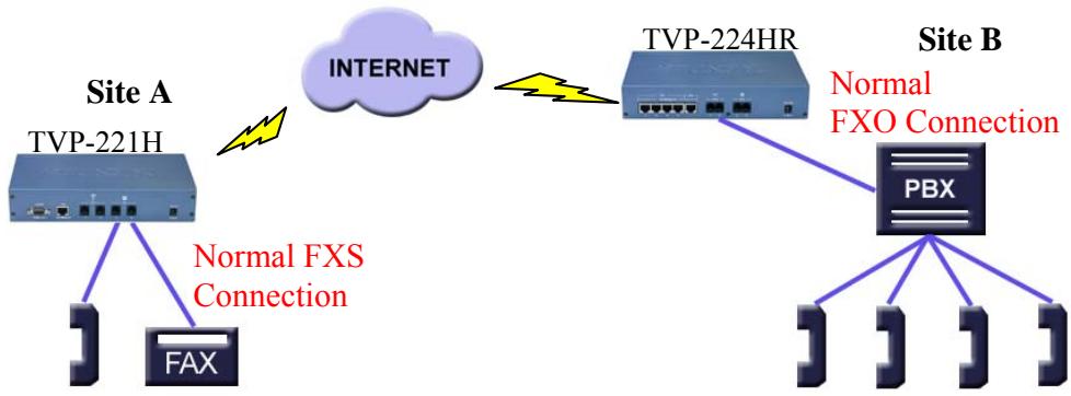
Chapter 12
Troubleshooting Tips
This section provides solutions for problems you may possibly encounter while installing and connecting your VoIP Gateway.
Overview
This chapter covers some common problems that may be encountered while using the TVP-224HR and some possible solutions to them. If you follow the suggested steps and the TVP-224HR still does not function properly, contact your dealer for further advice.
General Problems
Problem 1: Can't connect to the TVP-224HR to configure it. Solution 1: Check the following:
- The TVP-224HR is properly installed, LAN connections are OK, and it is powered ON.
- Ensure that your PC and the TVP-224HR are on the same network segment.
- If your PC is set to "Obtain an IP Address automatically" (DHCP client), restart it.
- If your PC uses a Fixed (Static) IP address, ensure that it is using an IP Address within the range 192.168.0.2 to 192.168.0.254 and thus compatible with the TVP-224HR's default IP Address of 192.168.0.1. Also, the Network Mask should be set to 255.255.255.0 to match the TVP-224HR. In Windows, you can check these settings by using Control Panel-Network to check the Properties for the TCP/IP protocol.
Internet Access
Problem 1: When I enter a URL or IP address I get a time out error.
Solution 1: A number of things could be causing this. Try the following troubleshooting steps.
- Check if other PCs work. If they do, ensure that your PCs IP settings are correct. If using a Fixed (Static) IP Address, check the Network Mask, Default gateway and DNS as well as the IP Address.
- If the PCs are configured correctly, but still not working, check the TVP-224HR. Ensure that it is connected and ON. Connect to it and check its settings. (If you can't connect to it, check the LAN and power connections.)
- If the TVP-224HR is configured correctly, check your Internet connection (DSL/Cable modem etc) to see that it is working correctly.
Problem 2: Some applications do not run properly when using the TVP-224HR.
Solution 2: The TVP-224HR processes the data passing through it, so it is not transparent.
- Use the Special Applications feature to allow the use of Internet applications which do not function correctly.
- If this does solve the problem you can use the DMZ function. This should work with almost every application, but:
- It is a security risk, since the firewall is disabled.
Note: Only one (1) PC can use this feature.
Other Problems
Power (PWR) LED is not illuminated
- Check the power adapter connection.
- If the power adapter or power cord is connected to the gateway, check that the cord is securely plugged into the power socket on the rear of the console.
- Check that the other end of the power adapter or power cord is securely plugged into the power outlet.
- If both ends of the power cord are properly connected and there is still no power, the gateway might have a faulty power outlet, power adapter or cord.
- Change to another power outlet or obtain another power adapter or cord.
LNK LED is not illuminated
- Check that the TVP-224HR was connected correctly:
a. Powered on
b. Correctly connected
- Make sure connectors at both ends are securely seated.
- Check the TVP-224HR IP setting is correct
Line port LED is not illuminated when I pick up the phone.
- Check the RJ11 telephone line to make sure it is correctly connected to both telephone set and line port
There is no dial tone when I pick up the phone.
- Check the Line port LED to make sure it is illuminated
- Check the RJ11 telephone line to make sure it is connected correctly to both phone set and line port
There is an out-of-service tone when dialing the destination phone number.
- Check the dial plan setting (address table, hunt group table and destination table) at the destination phone number
There is no connection tone when dialing the destination phone number
- Check the IP network (Ethernet cable, Ethernet port and GW IP setting) is connected correctly
- Check the destination TVP-224HR and phone is available
Final Steps
If the procedures in this section have not solved the problem, reset the gateway several times by turning the power on and off. If the problem still exists, contact customer support.
Appendix A - Technical Specifications
TVP-224HR Technical Specifications
| Telephony Interface | |
| Physical interface | Desktop with 4 Analog Ports • Loop start 2 x FXO (RJ-11) • Loop start 2 x FXS (RJ-11) |
| Programmable line interfaces | Complex line impedance |
| Protocols | H.323v3 (Normal/fast-start mode) Supports gateway-gateway direct routing and gateway-gatekeeper assisted routing mode |
| Voice coders support | ITU-T G.711 u-law, G.723.1, and G.729A/B, auto-switching (Frame-rate/packet: 1 - 8) |
| Fax | Supports T.30 G3 fax on PSTN Interface; ITU-T T.30 fax spoofing ; ITU-T T.38 |
| Simultaneous connections | 4 channels voice/fax |
| Media processing | Gain control; G.168 echo cancellation (16 ms); Voice activity detection (VAD); Comfort noise generation (CNG); Call progress detection; DTMF detetetection/filtering/regeneration (H.323v3/IMTCv1) |
| Data Network Interface | |
| Physical interface | WAN: 1 (10Base-T/100Base-TX, Auto-Negotiation) LAN: 4 (10Base-T/100Base-TX, Auto-Negotiation) |
| Protocols | TCP/IP, DHCP, HTTP, DNS |
| Advanced Function | QoS, Virtual Server, Port Forwarding Special application, DMZ, DDNS |
| System | |
| Call Control | Built-in three-tier dialing plan and destination huntingSupports gatekeeper authorization and accountingSupports gatekeeper call routing control and gateway mappingCall accounting information on gateway (via RS-232) orgatekeeper |
| Management | RS-232 (DCE mode)Built-in HTTP Web-based remote managementTelnet remote management |
| System upgrade | Flash memory and built-in TFTP allowing firmware and feature upgrade via network |
| Chassis | Metallic 9.5" Desktop |
| Dimensions (L X W X H) | 241 x 135 x 45 mm (9.5 x 4.3 x 1.8 in.) |
| Weight | 1.9 kg (4.2 lb) |
| LED Indicators | System: 2 PWR, CPU WAN: 1, LNK/ACT LAN: 4, LNK/ACT Voice: 4 In-Use/Ringing |
| Interoperability† | Microsoft NetMeeting*; Cisco AS5300, 3600; RADVISION gatekeeper; Cisco gatekeeper |
| Input Voltage, AC | 90–260 VAC, auto ranging, 50–60 Hz |
| Power Requirement | 12V DC, 2.0A |
| Operating environment | Operating temperature: 0° ~ 50°C (32° ~ 122°F) Humidity: 90% (non-condensing) |
| Certification | CE, FCC, UL |
| FXO Ports | |
| Signaling | Loop start/DTMF |
| Number of channels | 2 |
| Interface connectors | 2 RJ-11 2-pin modular jacks |
| Line impedance | 600 Ω; 900 Ω; Complex line impedance |
| Insertion loss | 2 dB nominal |
| Frequency response | 300 Hz ~ 3400 Hz +/- 2 dB w.r.t. 1004 Hz |
| Return loss | ≥18 dB |
| Input level adjustment | -6 dB to +6 dB |
| Output attenuation | 0 dB to 13 dB |
| Longitudinal balance | ≥45 dB |
| Disconnect detection | Loop current Customizable tone detection |
| FXS Ports | |
| Signaling | Loop start/DTMF |
| Number of channels | 2 |
| Interface connectors | 2 RJ-11 2-pin modular jacks |
| Line impedance | 600 Ω; 900 Ω; Complex line impedance |
| Insertion loss | 2 dB nominal |
| Frequency response | 300 Hz ~ 3400 Hz +/- 2 dB w.r.t. 1003 Hz |
| Return loss | ≥18 dB |
| Input level adjustment | -6 dB to +6 dB |
| Output attenuation | 0 dB to 13 dB |
| Longitudinal balance | ≥45 dB |
| Loop current | 25 mA nominal |
| Ring voltage | 40 Vrms nominal |
| Ringing tone | 16.67 Hz, 20 Hz (default), 25 Hz or 50 Hz |
| Disconnect detection | Loop current |
Console Port
The console port uses a DB-9 RS-232 connector. The supplied straight through RS-232 cable connects the console port of the TVP-224HR to a console PC or terminal. Pin assignment for the port is described in the following table.
| DB-9 pin | Signal |
| 1 | Not connected |
| 2 | TxD |
| 3 | RxD |
| 4 | Not connected |
| 5 | Ground |
| 6 | Not connected |
| 7 | Not connected |
| 8 | Not connected |
| 9 | Not connected |
LAN Port
The 10/100 LAN port use standard RJ-45 connector and Ethernet pin assignment. The following diagram and table show the pin assignment on the port connector. When connecting the LAN port to switches or repeaters, you must use a straight-through cable.
| RJ45 pin | Signal |
| 1 | RxD+ |
| 2 | RxD- |
| 3 | TxD+ |
| 4 | Not connected |
| 5 | Not connected |
| 6 | TxD- |
| 7 | Not connected |
| 8 | Not connected |
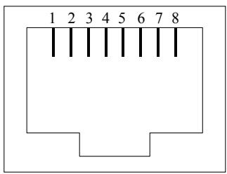
FXO Port Pin Assignments
The FXO Telephony Interface Module has 2 RJ11C/W modular jacks. The following diagram and table show the assignments of the pin for the RJ11 port.
| RJ-11 pin | Signal |
| 1 | Not connected |
| 2 | Tip |
| 3 | Ring |
| 4 | Not connected |
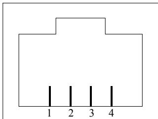
FXS Port Pin Assignments
The FXS Telephony Interface Module has 2 RJ11C/W modular jacks. The following diagram and table show the assignments of the pin for the RJ11 port.
| RJ-11 pin | Signal |
| 1 | Not connected |
| 2 | Tip |
| 3 | Ring |
| 4 | Not connected |
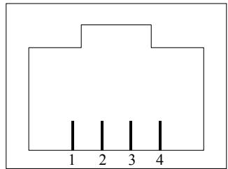
Appendix B - Connecting through Console
The console port uses a DB-9 RS-232 connector. The supplied straight through RS-232 cable connects the console port of the TVP-224HR to a console PC or terminal.
| Task | Prompt | Type |
| Connect RS-323 Cable to TVP-224HR RS-232 console port a your computer that you will use as a configuring terminal | ||
| Open HyperTerminal and enter the following Input Parameters when prompted: | Baud rate Number of data bit Parity check Number of stop bit Flow control | 19,200 8 None 1 None |
| When the empty HyperTerminal Screen appears type "123" | 123 | |
| In the event that you forget your administration password, you can gain console access to the TVP-224HR using the super password. The super password is the last six digits of your MAC address located on the bottom of your TVP-224HR (00-50-2d-xx-xx-xx). At the Console prompt enter the super password without hyphens. The password is all lower case. After gaining access, at the console prompt type in net set manager password <new_password> <new_password> net store net reset If entry of new password is successful, the console will list "OK". You will now be able to gain Web Access from a PC in the same local segment using the TVP-224HR LAN IP Address. If Web and / or Telnet Access are enabled, you will also be able to remote access the TVP-224HR by entering http://followed by the TVP-224HR WAN IP or domain name. | ||
| At the prompt Console> Enter ping 168.95.1.1 The following dialogue indicates that Internet Access is successful. | Console> | ping 168.95.1.1 |
| ping 168.95.1.1 1 out of 1 pings succeeded. Console>If the ping times out, you do not have Internet Access. Please refer to the trouble shooting section of the User Manual or consult your ISP to make sure your Internet Access Data is correct and accurately entered into the TVP-224HR. | ||
| The following commands enable / disable web and telnet access respectively. Net set http <on/off> Net set telnet <on/off> | Console> | on / off |
| To reset to Factory Default settings, please perform the following commands to: Erase all 'port', 'codec' & 'h323' configuration config erase Then access dial plan edit mode by entering atpm req Purge the dial plan from the database atpm purge all Store the changes atpm store Reset the network configuration to default net set fac_default Key in "yes" to re-boot. |
Appendix C - Connecting through Telnet
To use Telnet, Internet Access must have been previously setup so that the gateway is visible on the internet (See User Guide for More Information). Alternatively, you can use Telnet to locally access the TVP-224HR, if you are under a router or switch and the TVP-224HR and your computer are in the same network segment.
To access the TVP-224HR Gateway from a remote location using Telnet, perform the following tasks:
| Task | Prompt | Type |
| Open the windows command prompt and enter the telnet command followed by the IP address of the TVP-224HR Gateway you want to access. | None | telnet xxx.xxx.xxx |
| When the TVP-224HR Gateway prompts you to Login, enter the user name "admin" | Login: | admin |
| When the TVP-224HR Gateway prompts you for Password, enter the password. "Console>" will appear. The default password is "123" but it is recommended that the password be changed for security considerations. | Password: | 123 |
TVP-224HR User's Guide
| The password can be changed from the Web Browser Administration / Password submenu page. | ||
| Type in “ping xxx.xxx.xxx”, where xxx.xxx.xxx is your ISP provided DNS Server IP or any known Public Internet Address. The following dialogue confirms Internet Access Console>ping 168.95.1.1 ping <168.95.1.1>: 56 data bytes 168.95.1.1 is alive If the ping times out, you do not have Internet Access or the Public IP Address you pinged is incorrect. Try another IP Address. If you confirm that you do not have Internet Access, please refer to the trouble shooting section of the User Manual or consult your ISP to make sure your Internet Access Data is correct and accurately entered into the TVP-224HR. | Console> | ping xxx.xxx.xxx |
Normal Mode Commands
| Command | Description |
| atpm aadd | Add an entry to the address table |
| atpm adel | Delete an entry from the address table |
| atpm afind | Find and display an entry in the address table |
| atpm alist | Display all entries in the address table |
| atpm dadd | Add an entry to the destination table |
| atpm ddel | Delete an entry from the destination table |
| atpm dfind | Find and display an entry in the destination table |
| atpm dlist | Display all entries in the address table |
| atpm hadd | Add an entry to the hunt group table |
| atpm hdel | Delete an entry from the hunt group table |
| atpm hfind | Find and display an entry in the hunt group table |
| atpm hlist | Display all entries in the hunt group table |
| atpm done | End the atpm table update session |
| atpm erase | Erase all atpm tables from NVs |
| atpm purge | Purge entries from atpm table(s) |
| atpm req | Start atpm table update session |
| atpm restore | Restore atpm tables from NVS |
| atpm store | Store atpm tables into NVS |
| atpm slist | Display atpm system parameters |
| atpm sys | Set atpm system parameters |
| config activate | Move the configuration from temporary area to active area. |
| config erase | Erase the configuration from NVS |
| config store | Store the active configuration data into NVS |
| clrscr | Clear screen |
| download | Switch to download mode |
| help | Display help screen |
| net reset | Reset the system |
| net set wan gateway | Set default gateway's IP address |
| net set http | Turn on/off HTTP server |
| net set wan ip | Set IP address |
| net set ip_preced | Set IP precedence bits |
| net set wan mask | Set IP subnet mask |
| net set wan speed | Select Ethernet link speed |
| net set user_pw | Set password |
| net show | Display IP parameters |
| net show hwstat | Display hardware status |
| ping | Send ICMP echo request to another host |
| show h323 | Display H.323 parameter settings |
| show version | Show software versions |
| set h323 | Set H.323 parameters |
| tel show tel_id | Display line impendence setting. |
| tel show port | Display hook state for a telephony port |
| tel show ring_freq | Show ringer's frequency |
| tel set tel_id | Set line impendence for GW line interface |
| tel set ring_freq | Set ringer's frequency |
Download Mode Commands
| Command | Description |
| Help | Display help screen |
| Quit | Switch to normal operation mode |
| net set wan gateway | Set default gateway ‘s IP address |
| net set wan ip | Set IP address |
| net set wan mask | Set IP subnet mask |
| start | Start downloading file |
Appendix E - Factory Default Settings
The following table lists the settings of certain parameters before the TVP-224HR is shipped.
| Parameter | Default Setting |
| Network | |
| PPPoe | disabled |
| DYN DNS | disabled |
| DHCP Server | enabled |
| Configured IP address | 192.168.0.1 |
| Configured IP subnet mask | 255.255.255.0 |
| Default gateway IP address | 0.0.0.0 |
| Current active IP address | 192.168.0.1 |
| Current active subnet mask | 255.255.255.0 |
| IP precedence | 0 0 0 0 |
| Ethernet MAC address | 00-50-2d-xx-xx-xx |
| Ethernet link speed | 10/100 auto-negotiation |
| User ID for HTTP browser and Telnet client login | admin |
| Password for HTTP browser and Telnet access login | 123 |
| HTTP server | enabled |
| Telnet server | enabled |
| Serial port (Fixed) | |
| Baud rate | 19,200 |
| Number of data bit | 8 |
| Parity check | None |
| Number of stop bit | 1 |
| Flow control | None |
| H.323 | |
| h323 display_name | customer |
| h323 h245_term_type | 60 |
| h323 rtp_port_base | 30,000 |
| h323 out_fast_start | Off |
TVP-224HR User's Guide
| h323 in_fast_start | Off |
| h323 h245_tunneling | Off |
| h323 cisco_t38 | Off |
| h323 callSignalPort | 1720 |
| h323 call_name | None |
| h323 localalert | Off |
| h323 default_dtmf | H323 V2 Signal |
| h323 gk_mode | Off |
| h323 h245_timeout | 30000 |
| h323 term_id | None |
| 1 | |
| Voice codec | |
| Preferred voice codec | G.723 6.3kbps |
| Telephony | |
| PCM codec receiver gain for FXO ports | -1 dB |
IP Parameters
Consult your network manager to obtain a static IP address for the TVP-224HR, and the information about the IP subnet mask and the default gateway for your network. Fill out the following work sheet before configuring the TVP-224HR.
IP address
IP subnet mask
Default gateway
ATPM Destination Table
Local Destinations
Each telephony port of the TVP-224HR must be assigned a unique destination ID. Fill out the worksheet for local destinations by designating each port a unique destination ID, then use the CLI command atpm daddestid port port# for each entry in the worksheet to add it to the destination table. The dest_id in the command corresponds to the Destination ID in the worksheet, while the port# corresponds to the Port#. You may alternatively use the web browser to add local destinations to the destination table.
| Port# | Mode | Destination ID |
| 0 | port | |
| 1 | port | |
| 2 | port | |
| 3 | port |
Remote Destinations
Each remote TVP-224HR to be reached must be assigned a unique destination ID. Obtain the IP addresses of the TVP-224HR at remote sites and fill out the worksheet for remote destinations by designating each
remote TVP-224HR a unique destination ID, then use the CLI command atpm dadd dest_id h323 ip_addr [ip_port] for each entry in the worksheet to add it to the destination table. The dest_id in the command corresponds to the Destination ID in the worksheet, the ip_addr corresponds to the Port#, the optional ip_port corresponds to the IP port. You may alternatively use the web browser to add remote destinations to the destination table.
| IP address | IP port (optional) | Mode | Destination ID |
| . . . | H323 | ||
| . . . | H323 | ||
| . . . | H323 | ||
| . . . | H323 | ||
| . . . | H323 | ||
| . . . | H323 | ||
| . . . | H323 | ||
| . . . | H323 | ||
| . . . | F10000000000000000000000000000000000000000000000000000000000000000000000000000000000000000000000000000 | H323 | |
| . . . . | H323 | ||
| . . . . | H323 | ||
| . . . . | H323 | ||
| . . . . | H323 | ||
| . . . . | H323 | ||
| . . . . | H323 | ||
| . . . . | H323 | ||
| . . . . | H323 |
ATPM Hunt Group Table
Several destinations may be grouped together to form a hunt group. When an incoming phone number matches the phone number of the hunt group, the TVP-224HR attempts to terminate the call at each of the destinations in the hunt group one at a time until a call is successfully completed. Plan how destinations are to be grouped and fill out the hunt table worksheet, then use the CLI command atpm hadd hunt_group_id hunt_type dest_id for each entry in the worksheet to add it to the hunt group table. The hunt_group_id in the command corresponds to the Hunt Group ID in the worksheet, the hunt_type corresponds to the Hunt Type (1 or 2), the dest_id corresponds to the List of Destination IDs. You may alternatively use the web browser to add hunt groups to the hunt group table.
| Hunt Group ID | Hunt Type | List of Destination IDs | |
| 1 | 2 | ||
ATPM Address Table
Each phone number to be recognized by the TVP-224HR must have its first digits match an entry in the address table. Fill out the address table worksheet and use the CLI command
atpm aadd tel# min_digits max_digits hunt_group_id prefixStrip_len [prefix#] to add each entry in the worksheet to the address table. The tel# in the command corresponds to the Digits to Match in the worksheet, the min_digits corresponds to the Min. # of Digits to Collect, the max_digits corresponds to Max. # of Digits to Collect, the hunt_group_id corresponds to the Hunt Group, the prefixStrip_len correspond to No. of Digits to Strip and the prefix# corresponds to the Prefix String. You may alternatively use the web browser to add telephone numbers to the address table.
| Digits to Match | Min. # of Digits to Collect | Max. # of Digits to Collect | Hunt Group | No. of Digits to Strip | Prefix String |
Index
A
Address Table. 62
Administration. 78
Aliases 70
Append Prefix 73
ATPM. 4,61,115
Auto-Answer 69
C
Case 1 .89
Case 2. 89
Case 3. 90
Case 4. 91
Case 5 97
Case 6. 99
Case 7. 101
Channel Parameters. 78
Channel Status. 77, 79
Clear Dial Plan 76
CLI. 4,111
clients 90
CNG 12
Codec Selection. 77
Codes 64
Common Parameters 77
Concepts. 61
Console. 109
D
Dial plan. 62
DDNS. 90
Default Dial Plan. 80
DefaultDTMFMode. 69
desktop 17
destination 61
Destination ID Table 74
Destination Table 63, 88
DHCP 90
Dial Plan. 72, 82, 87
Dial Plan Setup. 72, 85
Display Name 68
Download Mode 112
DSP 4
DTMF. 4,61
DTMF Duration 69
DTMF relay. 63, 107
E
Endpoint Prefix 70
F
Factory Default Settings. 113
Firmware Version 67
First Digit Wait Time 78
Foreign Exchange Office See FXO
Foreign Exchange Station.. See FXS
Front Panel 14, 16
FXO. 4, 17, 103
FXO Port Pin Assignments.....110
FXO to FXS PLAR. 100, 102
FXS 4,17,103,104
FXS Port Pin Assignments.....110
FXS to FXO PLAR. 98
G
Gate Keeper. 69, 70
Gate Keeper Address 70
GateKeeper ID 70
Gateway 12
H
H.323. 4,61
H.323 Configuration 67
H.323 Parameters 68
Help. 79
Hotline. 97, 99, 101
HTTP setting mode 65
hunt group 62
Hunt Group ID 73
Hunt Group Table 63, 73, 88
1
ICMP 4
IMTC. 4
Incoming Fast Start 68
Installing 17
Inter Digit Wait Time. 78
Interface Speed. 79
Internet Telephony Gateway.....12
IP Parameters 115
K
KTS. 12
KTS. 4
L
LAN Port. 109
LED. 4, 15
77
M
Max Registration Retries. 70
Max.Digits. 73
Min.Digits 73
N
NAT Call Mode. 69
Network Requirements. 17
NVS. 4
0
Outgoing Fast Start 68
P
Password 65,78
PBX. 4,12
PLAR 97, 99, 101
PPPoE. 90
PSTN. 4
R
real-time 12
Rear Panel 16
Registration Type 70
Restore Dial Plan. 77
RTOS 12
RTP 4,14
RTP Port Base. 68
S
Scenario 83
Store Dial Plan 75, 76
Strip Length. 73
System Status 67
T
TCID 4
Technical Specifications 107
Telnet Access 79
Terminal ID 70
Terminal Type 68
Termination Digit 78
TFTP 4
TIM 4,61
Time To Live. 70
TNV 4
Total Time 78
Troubleshooting 105
U
UDP 4
User name. 65
UTP 4
V
VAD. 4, 12, 14
VoIP 12, 14
W
WAN 4
Worksheet 115
Limited Warranty
TRENDware warrants its products against defects in material and workmanship, under normal use and service, for the following lengths of time from the date of purchase.
TVP-224HR- 5 Years Warranty
If a product does not operate as warranted above during the applicable warranty period, TRENDware shall, at its option and expense, repair the defective product or part, deliver to customer an equivalent product or part to replace the defective item, or refund to customer the purchase price paid for the defective product. All products that are replaced will become the property of TRENDware. Replacement products may be new or reconditioned.
TRENDware shall not be responsible for any software, firmware, information, or memory data of customer contained in, stored on, or integrated with any products returned to TRENDware pursuant to any warranty.
There are no user serviceable parts inside the product. Do not remove or attempt to service the product by any unauthorized service center. This warranty is voided if (i) the product has been modified or repaired by any unauthorized service center, (ii) the product was subject to accident, abuse, or improper use (iii) the product was subject to conditions more severe than those specified in the manual.
Warranty service may be obtained by contacting TRENDware office within the applicable warranty period for a Return Material Authorization (RMA) number, accompanied by a copy of the dated proof of the purchase. Products returned to TRENDware must be pre-authorized by TRENDware with RMA number marked on the outside of the package, and sent prepaid, insured and packaged appropriately for safe shipment.
WARRANTIES EXCLUSIVE: IF THE TRENDWARE PRODUCT DOES NOT OPERATE AS WARRANCED ABOVE, THE CUSTOMER'S SOLE REMEDY SHALL BE, AT TRENDWARE'S OPTION, REPAIR OR REPLACEMENT. THE FOREGOING WARRANTYES AND REMEDIES ARE EXCLUSIVE AND ARE IN LIEU OF ALL OTHER WARRANTYES, EXPRESSED OR IMPLIED, EITHER IN FACT OR BY OPERATION OF LAW, STATUTORY OR OTHERWISE, INCLUDING WARRANTYES OF MERCHANTABILITY AND FITNESS FOR A PARTICULAR PURPOSE. TRENDWARE NEITHER ASSUMES NOR AUTHORIZES ANY OTHER PERSON TO ASSUME FOR IT ANY OTHER LIABILITY IN CONNECTION WITH THE SALE, INSTALLATION MAINTENANCE OR USE OF TRENDWARE'S PRODUCTS.
TRENDWARE SHALL NOT BE LIABLE UNDER THIS WARRANTY IF ITS TESTING AND EXAMINATION DISCLOSE THAT THE ALLEGED DEFECT IN THE PRODUCT DOES NOT EXIST OR WAS CAUSED BY CUSTOMER'S OR ANY THIRD PERSON'S MISUSE, NEGLECT, IMPROPER INSTALLATION OR TESTING, UNAUTHORIZED ATTEMPTS TO REPAIR OR MODIFY, OR ANY OTHER CAUSE BEYOND THE RANGE OF THE INTENDED USE, OR BY ACCIDENT, FIRE, LIGHTNING, OR OTHER HAZARD.
LIMITATION OF LIABILITY: TO THE FULL EXTENT ALLOWED BY LAW TRENDWARE ALSO EXCUSES FOR ITSELF AND ITS SUPPLIERS ANY LIABILITY, WHETHER BASED IN CONTRACT OR TORT (INCLUDING NEGLIGENCE), FOR
INCIDENTAL, CONSEQUENTIAL, INDIRECT, SPECIAL, OR PUNITIVE DAMAGES OF ANY KIND, OR FOR LOSS OF REVENUE OR PROFITS, LOSS OF BUSINESS, LOSS OF INFORMATION OR DATE, OR OTHER FINANCIAL LOSS ASING OUT OF OR IN CONNECTION WITH THE SALE, INSTALLATION, MAINTENANCE, USE, PERFORMANCE, FAILURE, OR INTERRUPTION OF THE POSSIBILITY OF SUCH DAMAGES, AND LIMITS ITS LIABILITY TO REPAIR, REPLACEMENT, OR REFUND OF THE PURCHASE PRICE PAID, AT TRENDWARE'S OPTION. THIS DISCLAIMER OF LIABILITY FOR DAMAGES WILL NOT BE AFFECTED IF ANY REMEDY PROVIDED HEREIN SHALL FAIL OF ITS ESSENTIAL PURPOSE.
Governing Law: This Limited Warranty shall be governed by the laws of the state of California.
AC/DC Power Adapter, Cooling Fan, and Power Supply carry 1 Year Warranty
TRENDnet
TRENDware, USA
What's Next in Networking
Product Warranty Registration
Please take a moment to register your product online. to TRENDware's website at http://www.TRENDNET.com
TRENDnet Technical Support
US/Canada Support Center
European Support Center
Contact
Telephone: 1(310) 626-6252
Fax: 1(310)626-6267
Email: support@trendnet.com
Tech Support Hours
7:30am - 6:00pm Pacific Standard Time Monday - Friday
Contact
Telephone
Deutsch: +49 (0) 6331/268-460
8:00am - 6:00pm Middle European Time
Monday - Friday
TRENDware International, Inc.
3135 Kashiwa Street. Torrance, CA 90505
http://www.TRENDNET.com
Copyright ©2005. All Rights Reserved. TRENDware International, Inc.
- FCC Notice
- CE Declaration of conformity
- Trademarks
- Copyright Statement
- How to Use This Manual
- Important Safety Instructions
- Warning
- Documentation Abbreviations
- Notation Conventions
- Table of Contents
- H.323 Configuration 67
- Dial Plan Settings 73
- Dial in PLAR / CID 76
- Store Dial Plan 77
- Restore Dial Plan 78
- Line Settings 78
- Channel Parameters 79
- Administration 79
- Channel Status 80
- Help 80
- CHAPTER 10 81
- MAKING CALLS WITH TVP-224HR 81
- Configuration Examples 81
- Making a call with TVP-224HR FXS Port 82
- Making a call with TVP-224HR FXO Port 83
- Web Browser Sample Dial Plan 83
- Making a call between Gateway A and Gateway B. 90
- VoIP in a Dynamic IP environment 92
- PPPoE, DHCP, and DDNS clients: 93
- Dial in PLAR (Hotline) - TVP-224HR / TVP-224HR 100
- CHAPTER 11 107
- TELEPHONY CONNECTIONS 107
- Port Configuration 107
- CHAPTER 12 109
- TROUBLESHOOTING TIPS 109
- Overview 109
- General Problems 109
- Internet Access 109
- Other Problems 110
- Appendix A - Technical Specifications 111
- Appendix B - Connecting through Console 115
- Appendix C - Connecting through Telnet 116
- Appendix D - CLI Commands 118
- Appendix E - Factory Default Settings. 120
- Chapter 1
- Overview
- Features
- Internet Access Features
- Advanced Internet Functions
- LAN Features
- Configuration & Management
- Security Features
- Networking Protocols
- Package Contents
- Front Panel
- LED Indicators
- Reset Button
- Rear Panel
- WAN / LAN / Console Ports
- Console
- Chapter 2
- Installing the TVP-224HR
- Network Requirements
- Installing the TVP-224HR
- Connecting to the telephony devices
- Connecting to the LAN Network
- Assigning an IP address to the TVP-224HR
- Hardware Installation Procedures
- Choose an Installation Site
- Connect LAN Cables
- Connect WAN Cable
- Power Up
- Check the LEDs
- Router Setup
- Configuration Program
- Preparation
- Using your Web Browser
- If you can't connect
- Home Screen
- Navigation & Data Input
- LAN Configuration
- TVP-224HR VoIP Gateway Router
- Home
- LAN Configuration Settings
- DHCP Server
- Buttons
- DHCP
- What does DHCP do?
- Using the TVP-224HR's DHCP Server
- Using another DHCP Server
- To Configure your PCs to use DHCP
- Windows Clients
- TCP/IP Settings - Overview
- Checking TCP/IP Settings - Windows 9x/ME:
- Using DHCP
- Using "Specify an IP Address"
- Checking TCP/IP Settings - Windows NT4.0
- Obtain an IP address from a DHCP Server
- Specify an IP Address
- Checking TCP/IP Settings - Windows 2000:
- Using a fixed IP Address ("Use the following IP Address")
- Checking TCP/IP Settings - Windows XP
- Internet Access
- For Windows 9x/ME/2000
- For Windows XP
- Accessing AOL
- Macintosh Clients
- Note:
- Linux Clients
- Fixed IP Address
- To act as a DHCP Client (recommended)
- Other Unix Systems
- Chapter 5
- Operation and Status
- Operation
- Once both the TVP-224HR and the PCs are configured, operation is automatic.
- System Status Screen
- System Status
- WAN Interface Parameters
- LAN Interface Parameters
- Firmware Version
- Figure 17: System Status Screen
- Chapter 6
- Internet Features
- Internet Access Configuration
- Fixed IP Network Settings
- Fixed / Dynamic IP Address
- Data - Fixed/Dynamic IP address Screen
- PPPoE Configuration
- WAN PPPoE Configuration
- Special Applications
- Special Applications Screen
- Special APP Setup
- Data - Special Applications Screen
- Outgoing Ports
- Using a Special Application
- DMZ
- Dynamic DNS (Domain Name Server)
- The Service works as follows:
- Dynamic DNS Screen
- Virtual Servers / Port Forwarding
- IP Address seen by Internet Users
- Virtual Servers Screen
- Connecting to the Virtual Servers
- Voice QoS
- Voice QoS Screen
- Voice QoS Settings
- Data - Voice QoS Screen
- Voice QoS Data
- Chapter 7
- Administration
- Administration Password Setup / Login
- Administrator Password Setup
- Remote Administration
- Service Acess Configuration
- Data - Remote Administration Screen
- To connect from a remote PC via the Internet
- Upgrade Firmware
- Firmware Update Settings
- Data – Upgrade Firmware Screen
- To perform the Firmware Upgrade:
- Access Control
- To use this feature:
- Access Control Screen
- Workgroup Setting Menu
- Common Port Assignment
- Chapter 8
- TVP-224HR Telephony
- Concepts
- How the TVP-224HR Operates
- ATPM
- Destination
- Hunt Group
- Dial Plan
- Address Table
- Hunt Group Table
- Destination Table
- DTMF Relay
- Voice CODECs
- Chapter 9
- Configuring VoIP from a Web
- Browser
- HTTP setting mode
- Main Menu Function Briefings
- Select Home
- H.323 Configuration
- H.323 Status Page
- H.323 Parameters
- Gatekeeper
- The following fields must be filled in when Gate Keeper Mode is set to either auto or manual.
- GateKeeper ID: To specify Gate Keeper's ID.
- Aliases
- Dial Plan Settings
- Dial Plan Setup
- Telephone Number Table
- Destination ID Table
- Dial in PLAR / CID
- Dial in PLAR Considerations and Limitations
- Store Dial Plan
- Clear Dial Plan
- Restore Dial Plan
- Line Settings
- Channel Status
- Codec Selection
- Common Parameters
- Common Settings
- Total Time
- First Digit Wait Time
- Inter Digit Wait Time
- Termination Digit
- Channel Parameters
- Administration
- Password (See Chapter 7)
- Telnet Access
- Interface Speed
- Channel Status
- Help
- Chapter 10
- Making Calls with TVP-224HR
- Configuration Examples
- Default Dial Plan
- Network
- Dial Plan
- Making a call with TVP-224HR FXS Port
- Operation:
- Making a call with TVP-224HR FXO Port
- Connection: Analogue PBX connects to FXO port
- Web Browser Sample Dial Plan
- Scenario description: Two gateways connected by a switch.
- Gateway A, 4 ports, is configured as follows:
- Gateway B, 4 ports, is configured as follows:
- Gateway A - IP setup:
- Gateway A: Dial Plan Setup
- How to Enter the Dial Plan
- Gateway B: Dial Plan Setup
- Gateway A and Gateway B Dial Plan Tables
- Making a call between Gateway A and Gateway B
- VoIP in a Dynamic IP environment
- PPPoE, DHCP, and DDNS clients:
- Case 4: Gateway Prefix-Simplified Gateway Phone to Gateway Phone
- Web Configuration of Dial Plan
- Enter "net reset"
- Enter "telnet 192.168.0.1"
- Enter "telnet
- TVP-221HTVP-224HR configuration (cable connection) on site B
- Web Configuration
- Local (from a PC in same Segment)
- Telnet / Console
- Web Configuration of Internet Access
- Telnet (from a PC in same Segment)
- Dial in PLAR (Hotline) - TVP-224HR / TVP-224HR
- Case Scenario:
- Chapter 11
- Telephony Connections
- Port Configuration
- FXS (Foreign Exchange Station)
- FXO (Foreign Exchange Office)
- Application 1: Special FXS Connections
- Application 2: FXO Connections
- Chapter 12
- Troubleshooting Tips
- General Problems
- Other Problems
- Power (PWR) LED is not illuminated
- LNK LED is not illuminated
- Line port LED is not illuminated when I pick up the phone.
- There is no dial tone when I pick up the phone.
- There is an out-of-service tone when dialing the destination phone number.
- There is no connection tone when dialing the destination phone number
- Final Steps
- Appendix A - Technical Specifications
- TVP-224HR Technical Specifications
- Console Port
- LAN Port
- FXO Port Pin Assignments
- FXS Port Pin Assignments
- Appendix B - Connecting through Console
- Appendix C - Connecting through Telnet
- Normal Mode Commands
- Download Mode Commands
- Appendix E - Factory Default Settings
- IP Parameters
- ATPM Destination Table
- Local Destinations
- Remote Destinations
- ATPM Hunt Group Table
- ATPM Address Table
- Index
- A
- C
- D
- E
- F
- G
- H
- 1
- K
- L
- M
- N
- 0
- P
- R
- S
- T
- U
- V
- W
- Limited Warranty
- TVP-224HR- 5 Years Warranty
- TRENDnet
- TRENDnet Technical Support
- US/Canada Support Center
- European Support Center
- Contact
- Tech Support Hours
- Telephone
Brand : TRENDNET
Model : TVP-224HR
Category : Network router