
NR1501 - AV Receiver MARANTZ - Free user manual and instructions
Find the device manual for free NR1501 MARANTZ in PDF.
| Product Type | 5.1 Channel AV Receiver |
| Brand | Marantz |
| Model | NR1501 |
| Dimensions (W x H x D) | 440 x 105 x 340 mm |
| Weight | 7.5 kg |
| Power Supply | 230 V AC, 50/60 Hz |
| Power Consumption | 280 W |
| Output Power | 50 W per channel (8 ohms, 20 Hz - 20 kHz, 0.08% THD) |
| HDMI Inputs | 3 inputs, 1 output (HDMI 1.3a) |
| Supported Audio Formats | Dolby TrueHD, DTS-HD Master Audio, Dolby Digital Plus, DTS-HD |
| Main Features | 1080p video upscaling, HD audio decoding, FM/AM radio, Audyssey acoustic correction |
| Audio/Video Inputs | 4 HDMI inputs, 2 component, 3 composite, 6 analog audio inputs, 2 optical, 1 coaxial |
| Outputs | 1 HDMI output, 1 subwoofer pre-out, 5-channel speaker terminals |
| Maintenance and Cleaning | Unplug the device before cleaning; use a soft, dry cloth. Do not use abrasive products. |
| Safety | Do not expose to moisture, splashes, excessive heat. Do not block ventilation slots. |
| Spare Parts and Repairability | Contact an authorized Marantz service center for any repairs. The device contains no user-serviceable parts. |
| General Information | Warranty: 2 years (subject to local conditions). Keep the purchase receipt. |
Frequently Asked Questions - NR1501 MARANTZ
User questions about NR1501 MARANTZ
0 question about this device. Answer the ones you know or ask your own.
Ask a new question about this device
Download the instructions for your AV Receiver in PDF format for free! Find your manual NR1501 - MARANTZ and take your electronic device back in hand. On this page are published all the documents necessary for the use of your device. NR1501 by MARANTZ.
USER MANUAL NR1501 MARANTZ
AV Surround Receiver
NR1501
ENGLISH
WARRANTY
For warranty information, contact your local Marantz distributor.
RETAIN YOUR PURCHASE RECEIPT
Your purchase receipt is your permanent record of a valuable purchase. It should be kept in a safe place to be referred to as necessary for insurance purposes or when corresponding with Marantz.
IMPORTANT
When seeking warranty service, it is the responsibility of the consumer to establish proof and date of purchase. Your purchase receipt or invoice is adequate for such proof.
FOR U.K. ONLY
This undertaking is in addition to a consumer's statutory rights and does not affect those rights in any way.
FRANÇAIS
GARANTIE
The NR1501 is in conformity with the EMC directive and low-voltage directive.

Français
- Do not expose the equipment to rain, moisture, dripping or splashing.
- Do not remove the cover from the equipment.
- Do not insert anything into the equipment through the ventilation holes.
- Do not handle the mains cord with wet hands.
- Do not cover the ventilation with any items such as tablecloths, newspapers, curtains, etc.
- No naked flame sources, such as lighted candles, should be placed on the equipment.
- No objects filled with liquids, such as vases, shall be placed on the equipment.
- When the switch is in the OFF position, the equipment is not completely switched off from MAINS.
- The equipment shall be installed near the power supply so that the power supply is easily accessible.
- Do not expose the unit to excessive heat such as direct sunlight, fire or the like.
Français
AVERTISSEMENTS
Thank you for choosing the Marantz product.
Please read this User Guide thoroughly to ensure proper operation and installation before using this product.
After reading this User Guide, be sure to keep this for your future reference.
ACCESSORIES CHECK
Before use, check the below accessories were included in the package.
Remote controller 1
- Batteries (AAA). 2
- AC power cord 1
AM loop antenna 1
FM antenna 1 - Microphone 1
- User guide. 1
CONTENTS
FEATURES 2
BEFORE USE 2
EQUIPMENT MAINS WORKING SETTING 2
DO NOT LOCATE IN THE FOLLOWING PLACES.....2
USAGE OF REMOTE CONTROLLER 3
NAMES AND FUNCTIONS. 4
FRONT PANEL 4
FL DIPLAY AND INDICATOR. 4
REAR PANEL 5
REMOTE CONTROLLER. 6
BASIC CONNECTIONS 8
SPEAKER PLACEMENT 8
CONNECTING SPEAKERS 8
CONNECTING AUDIO COMPONENTS 9
CONNECTINGVIDEOCOMPONENTS 10
CONNECTING HDMI COMPONENTS 11
CONNECTING THE ANTENNAS. 12
CONNECTING OF AC POWER CABLE 12
BASIC OPERATION 12
AMP OPERATION 12
TUNER OPERATION 14
This unit comes with the latest digital surround sound decoding technologies listed below. For further details, refer to "SURROUND MODE" (page 40).
- Dolby True HD
- Dolby Digital Plus
- Dolby Digital, Dolby Digital EX
- DTS-HD (Master Audio, Hi-Resolution Audio)
- DTS, DTS ES, DTS Neo:6, DTS 96/24
Dolby Pro-Logic IIx
AUTO SETUP SYSTEM
The unit has been provided with an auto setup function that uses a high-performance DSP (digital signal processor) to analyze the data obtained by measuring the characteristics of the speakers and the characteristics of the listening room using the high-performance microphone supplied and which, based on the results of this analysis and arithmetic calculation processing, compensates the frequency characteristics in such a way that the entire listening room becomes the optimum listening environment.
7-CHANNEL DISCRETE AMPLIFIER
A 7-channel discrete amplifier boasting a wide range over which it exhibits the same high-level performance is employed.
HDMI TERMINALS INCORPORATED
Incorporating an IC for HDMI (High-Definition Multimedia Interface) that is compatible with HDMI Ver1.3a, which is the most up-to-date version, makes it possible for the HDMI terminals to support the transmission of video signals compliant with the Deep Color and x.v.Color standards, while at the same time enabling them to support Dolby TrueHD, DTS-HD and Dolby Digital Plus used with Blu-ray discs and HD DVDs.
VIDEO CONVERTER FEATURED
The unit has an up-converter (that converts composite and component signals into HDMI signals) for the video signals using full digital processing.
WIDE-BAND COMPONENTVIDEO SELECTOR
Three input lines and one output line for the component video signals are featured. High-definition and other wide-band (80 MHz (-3 dB)) video signals are supported.
SLIM-LINE DESIGN FOR GREATER FREEDOM OF INSTALLATION
By endowing this unit with slim dimensions for a multi-channel AV receiver, users can even install it where space is at a premium.
OTHER FEATURES
32-bit latest DSP
- OSD (on-screen display) menu system enabling the settings to be selected on the TV screen
- Remote controller with preset functions
- Environmentally friendly low-power-consumption STANDBY mode
- Cursor buttons provided on the front panel
- AUX1 input terminals enabling a digital audio player or other component to be connected using 3.5 mm stereo mini jacks provided on the front panel
BEFORE USE
EQUIPMENT MAINS WORKING SETTING
Your Marantz product has been prepared to comply with the household power and safety requirements that exist in your area.
This unit can be powered by 230V AC only.
DO NOT LOCATE IN THE FOLLOWING PLACES
To ensure long-lasting use, do not locate the unit where:
- Exposed to direct sunlight.
- Near to sources of heat such as heaters.
- Highly humid or poorly ventilated.
Dusty. - Subjected to mechanical vibrations.
- On wobbly, inclined or otherwise unstable surfaces
- Near windows where there is a chance of exposure to rain, etc.
- On top of an amplifier or other component which dissipates a great deal of heat
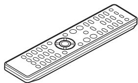
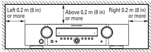
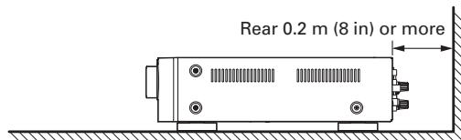
To ensure proper heat radiation, ensure the below clearance from walls and other equipment.
KEEP OBJECTS OFF
Keep objects off the unit. Blocking the vent can result in accident and damage.
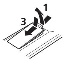
Before using the remote controller for the first time, load the batteries in the remote controller. The batteries provided are used to verify the operations of the remote controller only.
- Remove the battery cover.
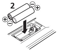
- Paying close attention to polarity indicators ( plus and minus), be sure to insert batteries correctly and as indicated.
- Return the battery cover to its original position.
CAUTIONS ON HANDLING BATTERIES
Misusing batteries can lead to fire, injury or soiling of surrounding area as a result of leakage, rupture or corrosion.
Carefully read the following precautions before using batteries.
- Insert the batteries while ensuring that their and poles are properly aligned with the corresponding markings on the remote controller.
- Batteries of the same size and shape may have different voltages. Do not use any battery except the type indicated. Do not use old and new batteries together, and do not use different types of batteries together.
- Do not recharge batteries.
- Keep batteries out of the reach of children. Seek medical attention if accidentally ingested.
- Do not carry or store batteries together with metal ball point pens, necklaces, coins, hair pins, etc.
- If you will not be using the remote controller for an extended time (1 month or more), remove the batteries to prevent leakage. If batteries leak, do not touch the fluid with bare hands. Wipe away any fluid in the case and put in new batteries. When doing so, handle with care, because fluid on skin or clothing presents a burn risk. If you accidentally get fluid on your skin, immediately wash with water and seek medical attention.
-
Do not heat or take apart batteries or put them in flame or water.
-
When disposing of used batteries, please comply with governmental regulations or environmental public instruction's rules that apply in your country or area.
- Do not expose the batteries to excessive heat such as direct sunlight, fire or the like.
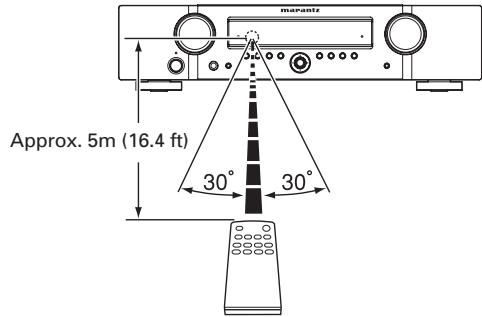
OPERATIONAL RANGE
Operate the unit with the remote controller within the range of the illustration below.
Caution
- Do not allow direct sunlight, an inverter fluorescent light or other strong source of light to shine onto the player's infrared receptor window. Otherwise, the operation of the remote controller may be disabled.
- Bear in mind that operating the remote controller may cause other devices operated by infrared rays to be operated by mistake.
- The remote controller cannot be operated if the space between the controller and the player's infrared receptor window is obstructed.
- Do not place any objects on top of the remote controller.
Doing so may cause one or more buttons to be held down which will cause the batteries to run down.
NAMES AND FUNCTIONS
FRONT PANEL
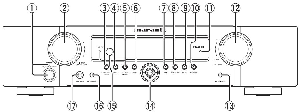
① POWER switch and STANDBY indicator
Press this button to turn the power ON, and press again to turn it OFF.
The STANDBY indicator lights up when this unit is the standby mode (power OFF) by the remote controller.
When this unit is in the standby mode with the POWER switch set to the ON position, pressing the
button also allows to turn the power on.
The STANDBY indicator lights up when this unit is the standby mode (power OFF) by the remote controller.
② INPUT SELECTOR knob
This knob is used to select the input sources. (See page 13)
③ SURROUND MODE button
Press this button to select the surround mode.
④ AUTO button
Press this button to select the AUTO mode from the surround modes. When this mode is selected, the unit determines the surround mode corresponding to a digital input signal automatically. (See page 27)
⑤ SOURCE DIRECT button and indicator
When this button is pressed, the audio signal will bypass the tone control circuit to provide the pure sound quality.
In order not to bypass the tone control circuit, press SOURCE DIRECT button again.
⑥ MENU button
Press this button to enter the SETUP MAIN MENU.
⑦ EXIT button
Press this button to exit from the SETUP MAIN MENU.
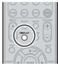
⑧ DISPLAY button
Press this button to change the FL display mode. (See page 26)
⑨ BAND button
Press this button to switch between FM and AM in the TUNER mode.
⑩ MEMORY button
Press this button to enter the tuner preset memory numbers or station names. (See page 29)
① HDMI indicator
This indicator is illuminated when input terminal of the HDMI component is connected to the unit.
⑫ VOLUME control knob
This knob is used to adjust the overall sound level. Turning the control clockwise increases the sound level.
13 AUX1 INPUT jack
This audio input jack accept the connections of the portable audio player etc.
⑭ Cursor (▲,▼,▲,▶) / ENTER button
Press these buttons to operate the SETUP MAIN MENU and TUNER function.
15 INFRARED receiving sensor window
This window receives infrared signals for the remote controller.
16 SETUP MIC jack
Automatically measure speaker characteristics using the included microphone. (See page 22)
17 PHONES jack
This jack may be used to listen to the unit's output through a pair of headphones. (See page 28)
FL DISPLAY AND INDICATOR
(1) Main Information Display
This display shows messages relating to the status, input source, surround mode, tuner, volume level or other aspects of unit's operation.
(2) AUTO indicator
This indicator is illuminated when the AUTO SURROUND mode is in use.
(3) RDS indicators
RDS : This indicator illuminates when an RDS signal is being received.
PTY: This indicator is illuminated when the PTY service is active.
(4) TUNER's indicators
ST: This indicator is illuminated in the AUTO STEREO mode during tuner operations.
TUNED : This indicator illuminates when the tuner receives a sufficiently strong radio signal.
(5) indicator
This indicator is illuminated when the sleep timer function is in use.
(6) MEM indicator
This indicator is illuminated when the MEMORY function is working during tuner operations.
(7) PRESET indicator
This indicator is illuminated in the PRESET mode during tuner operations.
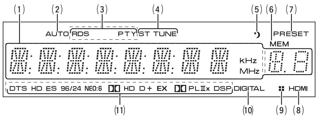
(8) HDMI indicator
This indicator is illuminated when a HDMI input source has been selected.
(9) indicator
This indicator is illuminated when this unit is in the display off mode.
(10) DIGITAL Indicator
This indicator is illuminated when a digital input has been selected.
(11) SIGNAL FORMAT indicators
DTS
This indicator is illuminated when a DTS signal is input.
DTS HD
This indicator is illuminated when a DTS-HD signal is input.
DTS ES
This indicator is illuminated when a DTS ES signal is input.
DTS 96/24
This indicator is illuminated when a DTS 96/24 signal is input.
NEO:6
This indicator is illuminated when the sound is output with the DTS Neo:6.
HD
This indicator is illuminated when a Dolby Digital True HD signal is input.
D D
This indicator is illuminated when a Dolby Digital signal is input.
D+
This indicator is illuminated when a Dolby Digital Plus signal is input.
DEX
This indicator is illuminated when a Dolby Digital EX signal is input.
DO PLIIx
This indicator is illuminated when the sound is output with the Dolby Pro Logic IIx.
DSP
This indicator is illuminated when the sound is output with the VIRTUAL or MULTI CH STEREO.
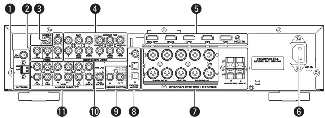
REAR PANEL
1 ANTENNA terminals
FM (75Ω)
Connect an external FM antenna with a coaxial cable, or a cable network FM source.
AM
Connect the supplied AM loop antenna. Position the loop antenna until you hear the best reception.
2VIDEO terminals (DVD,DSS,VCR)
There are 3 video inputs and 1 video output. Connect VCRs, DVD players, and other video components to the video inputs.
3 MONITOR OUT teminal
This is a monitor outputs.
4 COMPONENT VIDEO terminals (DVD, DSS, VCR)
This unit has 3 component video input connectors to obtain the color information (Y, P_B / C_B, P_R / C_R) directly from the recorded DVD signal or other video component and 1 component video output connector to output it directly into the matrix decoder of the display device.
HDMI terminals (BLU-RAY, GAME, DVD, DSS)
The unit has 4 HDMI inputs and 1 HDMI output.
6 AC INLET
Plug the supplied power cable into this AC INLET and then into the power outlet on the wall. This unit can be powered by 230V AC only.
SPEAKER SYSTEMS terminals
Seven terminals are provided for the front left, front right, front center, surround left, surround right, surround back left and surround back right speakers.
DIGITAL AUDIO IN 1,2,3
The unit has 1 digital input with coaxial jacks, 2 with optical jacks.
The inputs accept digital audio signals from a CD, DVD, or other digital source component.
The input function can be selected from the OSD menu system. (See page 20)
REMOTE CONTROL IN/OUT terminals
Connect to a Marantz component equipped with remote control (RC-5) terminals.
10 SUB WOOFER PRE OUT terminal
Connect this jack to the line level input of a powered subwoofer.
1 ANALOG AUDIO terminals (CD, DVD, DSS, VCR, AUX2)
There are 5 audio inputs and 1 audio outputs. The audio inputs and outputs require RCA-type connectors.
NAMES AND FUNCTIONS
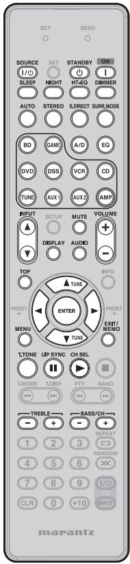
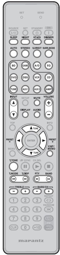
REMOTE CONTROLLER
The provided remote controller is a universal remote controller. The POWER button, numeric buttons and control buttons are used in common across different input source components.
The input source controlled with the remote controller changes when one of the input selector buttons is pressed.
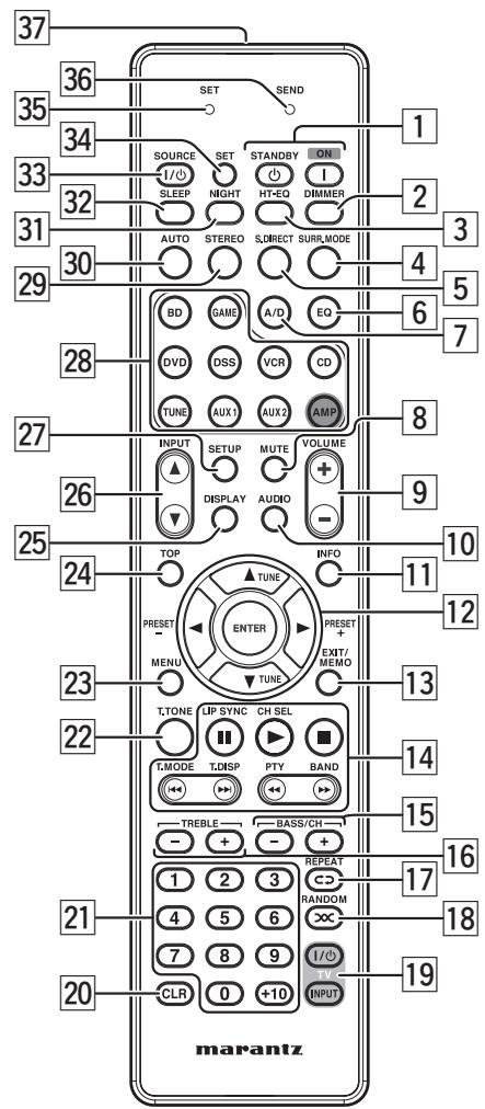
ON1/STANDBY 念 buttons
(When AMP mode is selected)
These buttons are used to turn the unit on or off.
DIMMER button
This button is pressed when dimming the unit's display.
3 HT-EQ button
(When AMP mode is selected)
This button is used to turn on or off HT(Home Theater)-EQ mode.
4 SURR. MODE button
This button is used to selects the surround mode.
S.DIRECT button
This button is used to select SOURCE DIRECT mode.
6 EQ button
This button is used to select Room EQ mode.
7 A/D button
This button is used to switch between the analog and digital inputs.
MUTE button
This button is used to mute the audio for the amplifier.
9 VOLUME + / - buttons
This button is used to adjust the volume for the amplifier.
10 AUDIO button
This button is used to select play using either the MAIN (main channel) sound or SUB (sub channel) sound in the Dolby Digital or DTS bilingual mode.
11 INFO button
This button is not used with this unit.
12 , , , (CURSOR) / ENTER buttons
These buttons are used when controlling the cursor of the unit, DVD or other AV equipment.
(When Tuner mode mode is selected)
PRESET + / PRESET - buttons
Used to select a preset station up and down.
TUNE /TUNE buttons
Used to tune a frequency station up and down.
13 EXIT / MEMO button
(When AMP mode is selected)
This button is used to cancel setting in the setup menu.
(When TUNER mode is selected)
This button is used to store the setting of preset channel and others.
14 CONTROL buttons
These buttons are used when operating PLAY, STOP, PAUSE and other commands of a source.
(When AMP mode is selected)
LIP SYNC button
This button is used to select LIP SYNC mode.
CH SEL button
This button is used to call up CH LEVEL ADJUST and adjust speaker levels.
(When TUNER mode is selected)
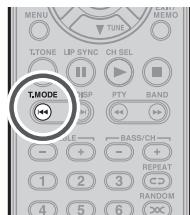
T.MODE button
This button is used to select auto stereo mode or mono mode when the FM band is selected.
T.DISP button
This button is used to select the display mode in RDS.
PTY button
This button is used to display the programme type information of the current station.
BAND button
This button is used to select a radio band.
15 BASS / CH +/- buttons
(When AMP mode is selected)
These buttons are used to adjust the tone control of low frequency sound for left and right speaker.
(When DSS mode are selected)
These buttons are used to change channels.
16 TREBLE +/- buttons
(When AMP mode is selected)
These buttons are used to adjust the tone control of high frequency sound for left and right speaker.
17 REPEAT c3 button
This button is used to select the REPEAT mode of a source.
18 RANDOM xx button
This button is used to select the RANDOM mode of a source.
19 TV CONTROL buttons
These buttons are used when operating of TV and Monitor.
20 CLR button
This button is used to erase the memory or program of a source.
21 Numeric buttons
These buttons are used to switch between 0 to +10 of the source components.
22 T.TONE button
This button is used to output test tones and set the speaker levels.
23 MENU button
(When AMP mode is selected)
This button is used to call up the SETUP MAIN MENU of the unit.
24 TOP button
Pressing this button during setup returns you to the top screen of the setup main menu.
25 DISPLAY button
This button is used to selects the display mode for the front display of the unit.
26 INPUT button
This button is for forward-feeding the input source to select a desired source.
INPUT button
This button is for backward-feeding the input source to select a desired source.
27 SETUP button
This button is used to setup for DVD and other device.
28 SOURCE button
These buttons are used to switch the source of your AV Receiver. Each time a source button is pressed, the remote controller changes to the source which was pressed.
This remote controller can control 10 types of equipment. To change the A/V Receiver source, press this button twice within two seconds. The signal is sent when it is pressed the second time.
Notes
- Press the AMP button to operate the unit's amplifier functions.
- Press the TUNE button to operate the unit's tuner functions.
29 STEREO button
This button is used to select STEREO mode.
30 AUTO button
This button is used to select auto surround.
31 NIGHT button
Pressing this button prevents the Dolby Digital signal from playback at a loud voice.
32 SLEEP button
This button is used for setting the sleep timer.
33 I / SOURCE ON/OFF button
This button is used to turn a specific source (such as a DVD player) on or off independently from the rest of the system.
34 SET button
This button is used to enter preset mode.
35 SET indicator
Indicates when the preset codes of the remote controller are operated.
36 SEND indicator
Indicates when the remote controller is transmitting a signal.
37 Infrared Transmitter
This transmitter emits infrared light. Press the buttons while pointing the transmitter towards the infrared receiver window of the unit or other AV equipment.
BASIC CONNECTIONS
SPEAKER PLACEMENT
The ideal surround speaker system for this unit is 7-speaker systems, using front left and right speakers, a center speaker, surround left and right speakers, a surround back left and right speakers, and a subwoofer. For best results we recommend that all front speakers be of the same type, with identical or similar driver units. This will deliver smooth pans across the front sound stage as the action moves from side to side. Your center channel speaker is very important as over 80% of the dialog from a typical motion picture emanates from the center channel.
It should possess similar sonic characteristics to the main speakers. Surround channel speakers need not be identical to the front channel speakers, but they should be of high quality.
The surround center speaker is useful for playback of Dolby Digital Surround EX or DTS-ES.
One of the benefits of both Dolby Digital and DTS is that surround channels are discrete full range, while they were frequency limited in earlier "Pro Logic' type systems.
Bass effects are an important part of home theater. For optimal enjoyment a subwoofer should be used as it is optimized for low frequency reproduction. If you have full range front speakers, however, they may be used in place of a subwoofer with proper setting of the switches in the menu system.
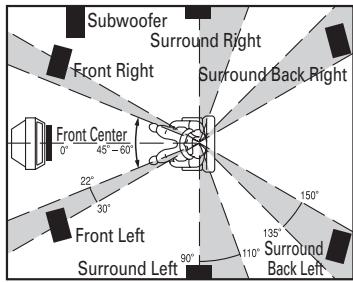
FRONT LEFT AND RIGHT SPEAKERS
We recommend to set the front L and R speakers with 45-60 degrees from the listening position.
CENTER SPEAKER
Align the front line of the center speaker with the front L/R speakers. Or place the center speaker a little backward from the line.
When this unit is used in surround operation, the preferred location for surround speakers is on the side walls of the room, at or slightly behind the listening position.
The center of the center speaker should face the center of the room.
Surround back speakers are required when a full 7.1-channel system is installed.
Speakers should be placed on a rear wall, behind the listening position.
The center of the speaker should face into the room.
SUBWOOFER
We recommend using a sub-woofer to have maximum bass effect. As the subwoofer only handles low frequencies, you can place it any where in the room.
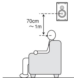
HEIGHT OF THE SPEAKER UNITS
FRONT LEFT AND RIGHT SPEAKERS,
AND A CENTER SPEAKER
Align the tweeters and mid-range drivers on the three front speakers at the same height, as best as possible.
Note
Use magnetically-shielded speakers for front left, right and the center speakers when the speakers are installed near the TV.
Place the surround left, right and surround back speakers higher than your ears by about 70cm-1m. Also place the speakers at the same height, as best as possible.
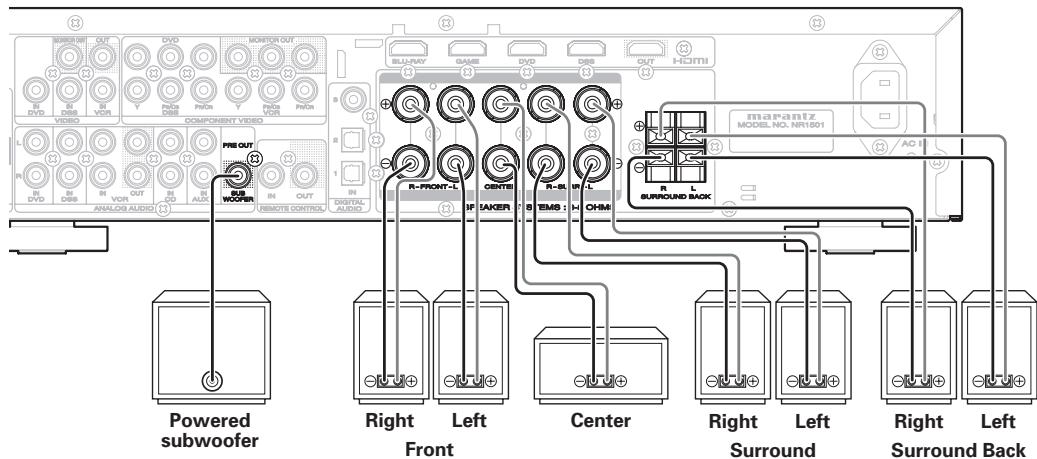
CONNECTING SPEAKERS
- Be sure to use speakers with the specified impedance as shown on the rear panel of this unit.
- When connecting a powered subwoofer (one with a built-in amplifier), connect it to the PRE OUT subwoofer output terminal.
Notes
- To prevent damage to circuitry, do not let the bare speaker wires touch each other and do not let them touch any metal part of this unit.

- Do not touch the speaker terminals when the power is on. It may cause you to receive an electric shocks.
- Do not connect more than one speaker cable to one speaker terminal. Doing so may damage this unit.
- Be sure to connect the positive and negative cables for the speaker properly. If they are miss-connected, the signal phase will be reversed and the signal quality will be corrupted.
CONNECTING SPEAKER WIRE
- Strip away approx. 10mm (3/8 inch) of wire insulation.
- Twist the bared wire ends tight, to prevent short circuits.
1.
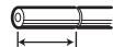
10mm
(3/8 inch)
2.

FRONT R/L
CENTER
SURROUND R/L
- Loosen the knob by turning it counterclockwise.
- Insert the bare part of the wire into the hole in side of each terminal.
- Tighten the knob by turning it clockwise to secure the wire.
3.

4.

5.

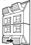
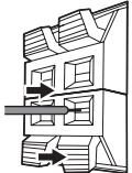
SURROUND BACK R/L
- Push the lever and hold it down.
- Insert the twisted ends of the wires into the hole in the terminal.
- Release the lever.
3.
4.
5.

CONNECTING AUDIO COMPONENTS
The VCR OUT terminals are for recording purposes. The sound of the analog input source component currently selected is output from these terminals.
The digital sound, which has been input to the DIGITAL IN or HDMI terminal, is not output from the VCR OUT terminals.
Notes
- Do not connect this unit and other components to mains power until all connections between components have been completed.
- Insert all plugs and connectors securely. Incomplete connections may make noise.
- Be sure to connect the left and right channels properly.
Red connectors are for the R (right) channel, and white connectors are for the L (left) channel.
- Be sure to connect input and output properly.
- Refer to the instructions for each component that is connected to this unit.
- Do not bundle the connected cables with the power cord or speaker cables. Doing so may produce noise.
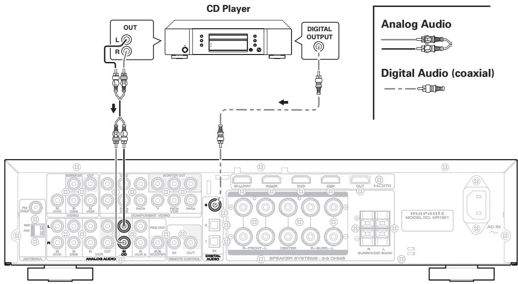
CONNECTING DIGITAL AUDIO COMPONENTS
- There are 3 digital inputs, 2 coaxial jacks and 1 optical jack, on the rear panel. You can use these jacks to input PCM, Dolby Digital and DTS bitstream signals from a CD, DVD, or other digital source components.
- Refer to the instructions for each component. To setup the digital audio format of DVD player, or other digital source's connected to digital input jacks.
- Use fiber optical cables (optical) for DIGITAL AUDIO-1,2 input jacks. Use 75 ohms coaxial cables (for digital audio or video) for DIGITAL AUDIO-3 input jacks.
- You can designate the input for each digital input/output jacks according to your component. (See page 20)
Note
- The digital signal jacks on this unit conform to the EIA standard. If you use a cable that does not conform to this standard, this unit may not function properly.
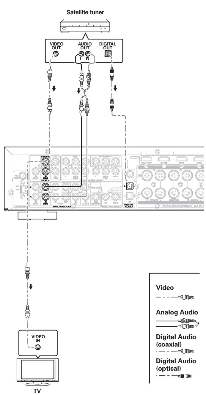
CONNECTINGVIDEOCOMPONENTS
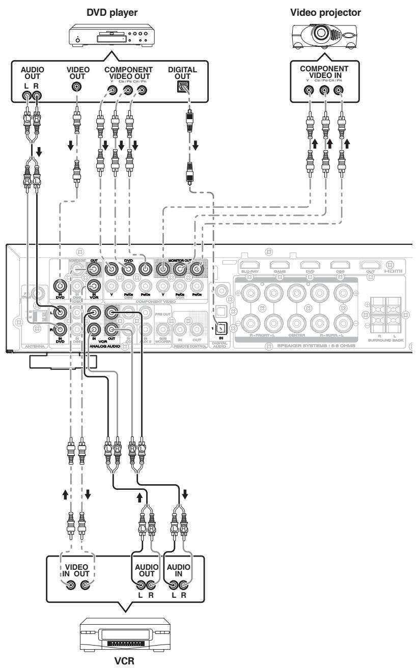
VIDEO COMPONENT JACKS
There are 2 types of video jacks on the rear panel.
VIDEO JACK
The video signal for the VIDEO jacks is the conventional composite video signal.
COMPONENT JACK
Make component video connections to a TV or monitor with component inputs to produce higher quality video images. Use a component video cable or 3 video cords to connect the component video out jacks on the unit to the monitor.
Notes
- Be sure to connect the left and right audio channels properly.
Red connectors are for the R (right) channel, and white connectors are for the L (left) channel. - Be sure to connect the inputs and outputs of the video signals properly.
- The unit has a video convert function. For details on video input/output, refer to page 29.
- You may need to setup the digital audio output format of your DVD player, or other digital source components. Refer to the instructions of the each component connected to the digital input jacks.
CONNECTING HDMI COMPONENTS
HDMI JACKS
This unit has 4 HDMI inputs and 1 HDMI output. It can send digital video and audio signals from Blu-ray's and other sources directly to a display. It minimizes signal degradation caused by analog conversion so that high quality images can be enjoyed.
Notes
- When the HDMI output is connected to a display monitor that does not support HDCP*, signals are not output. To view images in HDMI, it is necessary to connect to a display that supports HDCP.
- Refer to the instruction manual of the TV or display to be connected to the unit for detailed information regarding the HDMI terminal.
- HDCP: High-bandwidth Digital Content Protection
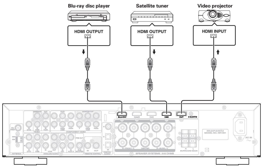
CONNECTING HDMI COMPONENTS
An HDMI cable (sold separately) is used to connect the HDMI jack on the unit with the HDMI jack on the Blu-ray disc player, TV, projector or other component. To transmit multichannel audio via HDMI, the connected player must support multichannel audio transmission through its HDMI jack.
Notes
- Some source devices such as DVD players or set top box do not support HDMI repeater operations like those of the unit. In such case, pictures are not properly projected on monitors such as TVs and projectors.
- When multiple components are connected to this unit, turn power to unused components off to prevent interference between them.
- Disconnecting or connecting cables with the power on can damage the equipment. Turn the power off before disconnecting or connecting cables.
-
The following functions are not available when the unit is connected to equipment that does not support HDMI 1.3a.
-
Deep Color
-
x.v. Color
-
Bitstream audio signal decoding, as for Dolby Digital Plus, Dolby TrueHD, DTS-HD, and so on. For details, refer to the user's manuals of connected equipment.
-
Depending on the quality of the cable used, the HDMI signal may be affected by noise.
- The unit does not support HDMI control. However, it can be connected between devices that support HDMI control, and the HDMI control signals can be passed through the unit to exercise the control concerned ("HDMI control through" function).
"HDMI control" is a function that lets one device control another when both feature HDMI CEC (Consumer Electronics Control). By using HDMI cables to connect the devices, linked operations can be performed between them.
BASIC CONNECTIONS
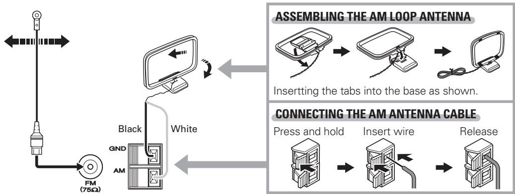
CONNECTING THE ANTENNAS
CONNECTING THE SUPPLIED ANTENNAS
The supplied antennas are for indoor use only.
Notes
- During use, extend the FM antenna and move it in various directions until the clearest sound is received.
Fix it with push pins or similar implements in that cause the least amount of distortion. - Set in the direction and position it to where you receive the clearest sound. Put it as far away as possible from the unit, televisions, speaker cables and power cable.
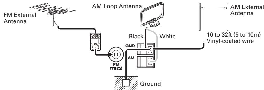
CONNECTING AN OUTDOOR ANTENNAS
If you experience poor reception quality, an outdoor antenna may improve the quality.
Keep the antenna from noise sources (neon signs, busy roads, power lines, transformers, etc)
Notes
- Do not remove the AM loop antenna.
- Do not connect the supplied FM antenna.
- The GND terminal on this unit does not function as a safety ground.
CONNECTING OF AC POWER CABLE
- Plug the supplied AC power cable to the AC IN socket on the rear panel of the main unit.
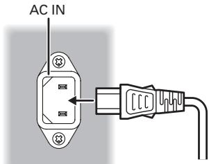
- Plug the power cable into an AC outlet.
BASIC OPERATION
AMP OPERATION
TURNING ON THE UNIT
- Turn the power of the equipment connected to this unit on.
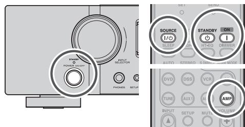
- Press the POWER ON/OFF button on the unit. The power of the unit switches on/off each time this button is pressed.
Pressing POWER OFF or SOURCE ON/OFF after pressing the AMP button on the remote controller causes the STANDBY indicator on the unit to light, and the unit to go into standby mode.
To turn the power on while in standby mode, press the AMP button on the remote controller, then press POWER ON or SOURCE ON/OFF.
SELECTING AN INPUT SOURCE
Before you can listen to any input media, you must first select the input source on the unit.
Example : DVD
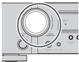
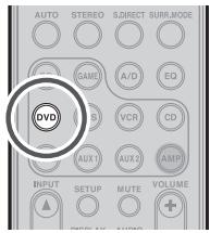
To select DVD, turn the INPUT SELECTOR knob on the front panel or press the DVD button on the remote controller two times in a row. After you have selected DVD, simply turn on the DVD player and play the DVD.
- As the input source is changed, the input name will appear in the display, on the front-panel.
- If you use the FUNCTION RENAME feature (see page 20), the renamed name appears on the display.
- As the input is changed, this unit will automatically switch to the digital input and surround mode, which were entered during the configuration process for that source.
ADJUSTING THE MAIN VOLUME
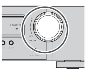
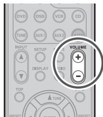
Adjust the volume to a comfortable level using the VOLUME control knob on the front panel or VOLUME + / - buttons on the remote controller. To increase the volume, turn the VOLUME knob clockwise or press VOLUME + button on the remote controller, to decrease the volume, turn counterclockwise or press VOLUME - button on the remote controller.
Note
- If the channel level has been set to +1 dB or more using the CHANNEL LEVEL setting, the maximum volume level will be reduced to below 80. (See page 24.)
ADJUSTING THE TONE (BASS & TREBLE) CONTROL
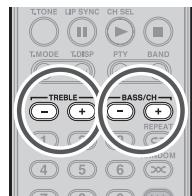
During a listening session you may wish to adjust the Bass and Treble Control to suit your listening tastes or room acoustics.
(Using the remote controller)
To adjust the tone, press the AMP button.
To adjust the bass effect, press BASS + or BASS - button.
To adjust the treble effect, TREBLE + or TREBLE - button.
Notes
The tone control functions cannot be used in the modes given below.
- SOURCE DIRECT mode
- When the ROOM EQ function is used
TEMPORARILY TURNING OFF THE SOUND
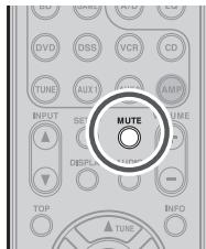
To temporarily silence all speaker outputs such as when interrupted by a phone call, press the MUTE button on the remote controller.
This will interrupt the output to all speakers and the head-phone jack, but it will not affect any recording or dubbing that may be in progress.
When the system is muted, the display will show "MUTE".
Press the MUTE button again to return to normal operation.
BASIC OPERATION
TUNER OPERATION
To operate the unit from the remote controller, press the TUNE button on the remote controller so that the tuner mode is engaged.
LISTENING TO THE TUNER
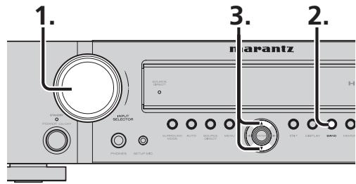
Frequency scan step for AM is selectable.
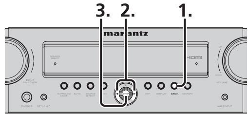
- Default setup is 9kHz step, if your country's standard is 10kHz step.
Press BAND button on the front panel.
-
"AM 9kHz" appears on the display.
-
Press the or cursor buttons on the front panel.
- "AM 10kHz" appears on the display, and the tuning increment is switched to 10 kHz.
- Press ENTER button on the front panel.
Note
- Preset memory for the tuner will clear by changing this setup.
AUTO TUNING
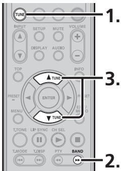
(Using the unit)
- Turn the INPUT SELECTOR knob to select "TUNER".
- Press the BAND button to select either FM or AM.
- Press the or cursor buttons on the front panel for more than 0.5 second to start the auto tuning function.
- Automatic searching begins then stops when a station is tuned in.
(Using the remote controller)
- To select tuner, press the TUNE button twice within two seconds on the remote controller.
- Press the BAND button to select either FM or AM.
- Press and hold the TUNE or button for 0.5 second or more.
- Automatic searching begins then stops when a station is tuned in.
If tuning does not stop at the desired station, use to the "Manual tuning" operation.
MANUAL TUNING
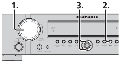
(Using the unit)
- Turn the INPUT SELECTOR knob to select "TUNER".
- Press the BAND button to select either FM or AM.
- Press the or cursor buttons on the front panel to select the desired station.
(Using the remote controller)
- To select tuner, press the TUNE button twice within two seconds on the remote controller.
- Press the BAND button to select either FM or AM.
- Press the TUNE or button to tune in the desired station.
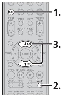
SWITCHING THE FM MODE
FM broadcasts are usually received in stereo, but when the quality of the signals received from a station that broadcasts programs in stereo is poor, the amount of accompanying noise may be significant.
In a case like this, by selecting the FM monaural mode, the level of the noise will be reduced, making it more pleasant to listen to the FM program.
- When the T.MODE button on the remote controller is pressed during FM reception, the ST indicator on the display goes off, and the FM monaural mode is established.
- When the T.MODE button is pressed again, the ST indicator illuminates, and the stereo mode is restored.
To control the unit by your remote controller, you have to select the device AMP or TUNER by pressing the SOURCE button. Please refer below for the details in AMP and TUNER mode.
AMP MODE
| SOURCE | Turns on the unit's power; sets the power to standby |
| STANDBY | Sets the unit's power to standby |
| ON | Turns on the unit's power |
| SLEEP | Sets or releases the sleep timer |
| NIGHT | Turns the NIGHT mode on and off |
| HT-EQ | Turns the HT-EQ on and off |
| DIMMER | Switches the brightness level of the display |
| AUTO | Selects the AUTO SURROUND mode |
| STEREO | Selects the STEREO mode |
| S.DIRECT | Selects the SOURCE DIRECT mode |
| SURR.Mode | Switches the surround mode |
| SOURCE | Selects the source components |
| A/D | Switches between auto, HDMI, digital and analog input |
| EQ | Turns the ROOM EQ on and off |
| AMP | Sets the remote controller to the AMP mode |
| INPUT▲/▼ | Selects the unit's input selector setting |
| MUTE | Temporarily mutes the sound |
| VOLUME+/- | Adjusts the volume level |
| DISPLAY | Selects the display mode |
| TOP | Returns to the top of the menu screen while the setup menu is displayed |
| Cursor | Moves the cursor while the setup menu is displayed |
| ENTER | Checks the settings while the setup menu is displayed |
| MENU | Displays the setup menu |
| EXIT/MEMO | Exports the setup menu |
| T.TONE | Starts the test tones |
| LIP SYNC | Sets the LIP SYNC function |
| CH-SEL | Adjusts the level between the speakers |
| TREBLE+/- | Adjusts the treble sound |
| BASS+/- | Adjusts the bass sound |
TUNER MODE
| SLEEP | Enables the corresponding function in the AMP mode |
| NIGHT | |
| HT-EQ | |
| DIMMER | |
| AUTO | |
| STEREO | |
| S.DIRECT | |
| SURR Modes | |
| SOURCE | |
| A/D | |
| EQ | |
| AMP | |
| INPUT ▲/▼ | |
| MUTE | |
| VOLUME+/- | |
| DISPLAY | |
| AUDIO | |
| TUNE ▲/▼ | Adjusts the frequency tuned |
| PRESET+/- | Selects a station stored in the preset memory |
| EXIT/MEMO | Registers a station in the preset memory |
| T-TONE | Enables the corresponding function in the AMP mode |
| T-MODE | Switches between FM auto stereo and monaural |
| T-DISP | Selects the display mode in RDS |
| PTY | Displays the programme type information of the current station |
| BAND | Switches the frequency band (between FM and AM) |
| TREBLE+/- | Enables the corresponding function in the AMP mode |
| BASS+/- |
ADVANCED CONNECTIONS
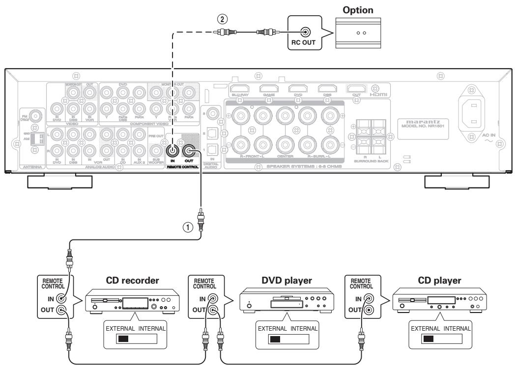
CONNECTING THE REMOTE CONTROL JACKS
①
You can control other Marantz products through this unit with the remote controller by connecting the REMOTE CONTROL terminals on each unit.
The signal transmitted from the remote controller is received by the remote sensor on this unit. Then the signal is sent to the connected device through this terminal. Therefore you need to aim the remote control only at the unit. Also, if a Marantz power amplifier (some models excluded) is connected to one of these terminals, the power amplifier's, power switch is synchronized with this unit's power switch.
Set the REMOTE CONTROL SWITCH on the back of other units (not the NR1501) to "EXT." (EXTERNAL) to use this feature.
②
Whenever external infrared sensors or similar devices are connected to RC-5 IN of the unit, be sure to always disable operation of the infrared sensor on the unit by using the following procedure.
- Hold down the cursor button and the MENU button on the front panel at the same time for five seconds.
- The setting "ENABLE" is shown on the FL DISPLAY.
- Press the CURSOR buttons (▲,▶) to change this to "DISABLE".
- Press the ENTER button. Once this setting is made, the infrared sensor on the unit is disabled.
Note
-
Be sure to set to "ENABLE" when external infrared sensors or similar devices are not connected. Otherwise, the unit will be unable to receive remote control commands.
-
To restore the original setting, perform steps 1 to 4 to set to "ENABLE".
SETUP
After all components are connected, initial setup must be performed.
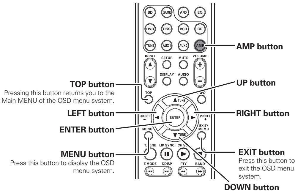
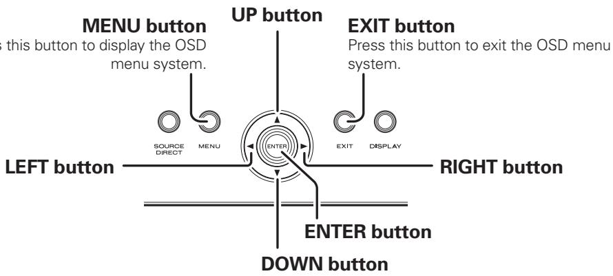
ONSCREEN DISPLAY MENU SYSTEM
This unit incorporates an onscreen menu system, which makes various operations possible by using the cursor ( , , ,) and ENTER buttons on the remote controller or on the front panel.
Note
-
To view the onscreen displays, make certain you have connected the MONITOR OUT jack on the rear panel to the composite, component video or HDMI input of your TV or projector. (See page 10, 11)
-
Press the AMP button on the remote controller. (This step is not needed when operating the setup menus from the unit.)
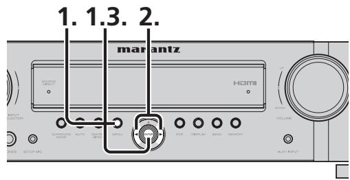
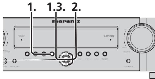
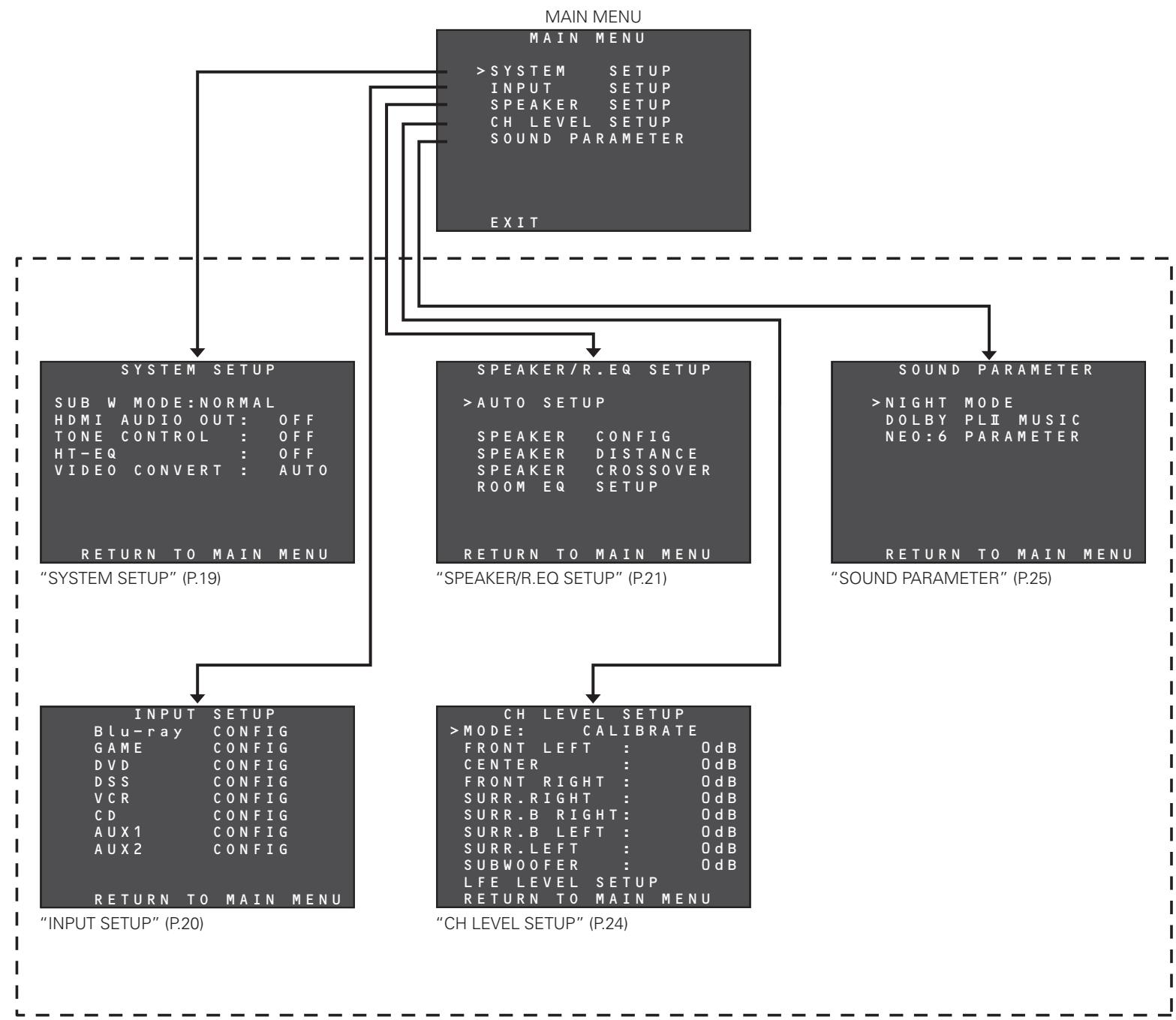
- Press the MENU button on the remote controller or press the MENU button on the front panel. The "MAIN MENU" of the OSD menu system is displayed.
There are 5 items in the MAIN MENU.
- Select the desired sub-menu with the or cursor buttons and press the ENTER button. The display will change to the selected sub-menu.
- To exit from OSD menu system, press the EXIT button, or move the cursor to EXIT and press the ENTER button.
SWITCHING BETWEEN PAL AND NTSC SIGNAL FORMATS
Select the video signal format (PAL or NTSC) used to view the on-screen display menu system.
- The default setting is the PAL signal format.
If the TV monitor used is an NTSC format monitor, hold down the MENU button and ENTER button simultaneously on the front panel for 3 seconds.
-
"PAL" appears on the display.
-
Press the or cursor button on the front panel.
- "NTSC" appears on the display, and the video signals of the on-screen display menu are switched to the NTSC format.
- Press the ENTER button on the front panel.
SWITCHING THE ON SCREEN DISPLAY OUTPUT MODE
Set whether the on screen display menu is operated by the monitor connected to theVIDEO OUT terminal or the monitor connected to the COMPONENTVIDEO MONITOR OUT terminal.
- Hold the MENU and ENTER buttons down simultaneously on the front panel for 3 seconds.
-
"PAL" appears on the display.
-
Press the or cursor button on the front panel.
-
"COLOR OFF" appears on the display. Menu operation switches to the monitor connected to the COMPONENT VIDEO MONITOR OUT terminal.
-
"COLOR ON" appears on the display. Menu operation switches to the monitor connected to the VIDEO OUT terminal.
-
Press the ENTER button on the front panel.
Note
When operating the on screen display menu using the monitor connected to the HDMI OUT terminal, either setting may be used without problem.
RC006SR BUTTON CONTROL
NR1501 FRONT BUTTON CONTROL
SETUP
Note
After you complete this portion of the setup, move cursor to "RETURN TO MAIN MENU" with the , , and cursor buttons and press the ENTER button.
1. SYSTEM SETUP
The unit's main functions are set following the steps below.
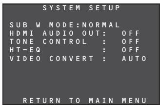
Press the / cursor buttons to move the cursor to the items to be set up.
1-1 SUBWMODE
The subwoofer mode setting takes effect only when the front speaker has been set to FULL RANGE and the subwoofer to YES.
This menu item setting takes effect only when PCM or analog stereo source signals are played.
Tip
For the settings of each speaker, refer to "3. SPEAKER/R.EQ SETUP" (page 21).
Press the cursor buttons to select NORMAL or SW PLUS+.
NORMAL
The bass sound is reproduced through the main left and right speakers only.
- SW PLUS+
The bass sound is reproduced through the main left and right speakers and subwoofer. In this playback mode, the bass sound dispenses uniformly throughout the entire room. However, depending on the size and shape of the room, interference may arise, reducing the actual volume level of the bass sound.
1-2 HDMI AUDIO OUT
This menu item is used to set whether the audio signals that have been input from the HDMI terminal are to be reproduced through the speakers connected to the unit or through the TV or projector connected to the unit's HDMI OUT terminal.
Press the cursor buttons to select ON or OFF.
OFF
The audio signals that have been input from the HDMI terminal are reproduced through the unit. In this case, sound audio signals will not be output from the TV or projector connected to the unit's HDMI OUT terminal.
ON
The audio signals that have been input to the HDMI terminal are not output from the unit's speaker terminals. Instead, the audio data is output straight to the TV or projector connected to the unit's HDMI OUT terminal. This menu setting is used to listen to sound through a TV with a multi-channel capability.
1-3 TONE CONTROL
This menu item is used to switch the tone controls to ON or OFF and set the tone controls.
Press the cursor buttons to select ON or OFF.
OFF
The tone control function is disabled.
ON
The tone control function is enabled.
If the ENTER button on the remote controller is now pressed, the OSD menu appears on the display, and the tone control settings can be selected.
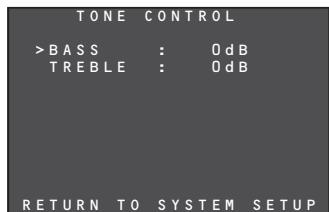
Press the / cursor buttons to select BASS or TREBLE. Then press the / cursor buttons to increment or decrement the decibel values shown. The tone controls can be adjusted in 2 dB steps up to +/-10 dB.
After adjusting the tone controls, move the cursor to RETURN TO SYSTEM SETUP, and press the ENTER button.
Notes
The tone control function cannot be used in the modes listed below.
- SOURCE DIRECT mode
1-4 HT-EQ
When movies are played using audio components designed for the home, the treble range in their sound tracks is boosted, sometimes producing a somewhat shrill sound. This is because these sound tracks are designed to be played in the very large spaces inside movie theaters. However, if the HT-EQ function is enabled when watching movies designed for viewing at the movie theater, the sound will be compensated so that the appropriate tonal balance is attained.
Press the cursor buttons to select ON or OFF.
The HT-EQ function cannot be used in the model listed below.
1-5VIDEOCONVERT
This menu item is used to set the function for up-converting the analog video signals (video and component video signals) that are input to the unit to HDMI output signals.
Press the cursor buttons to select AUTO, COMPONENT, CVBS or OFF.
- AUTO
With this menu item setting, when there are no HDMI signals in the selected input function, the video or component video signals are detected automatically and up-converted to HDMI output signals.
When both video and component video signals have been input, priority is given to up-converting the component video signals.
- COMPONENT
With this menu item setting, the component video signals that have been input to the unit are upconverted to HDMI output signals.
CVBS
With this menu item setting, the video signals that have been input to the unit are up-converted to HDMI output signals.
OFF
With this menu item setting, the unit's video-convert function is shut down.
Notes
- Only HDMI input signals can be connected to the BLU-RAY and GAME terminals on the unit's rear panel, so the video-convert function will not work.
- HDMI digital video signals cannot be downconverted to analog video signals.
- The signals up-converted to HDMI output signals are output without any processing at the resolution of the analog video signals that were input. When up-converting video or component video signals with a 480i resolution, a video monitor (TV set) supporting the 480i resolution must be connected to the unit.
- Some analog video signals that are input to the unit cannot be detected automatically. In a case like this, select COMPONENT or CVBS, and use the signals in a fixed mode.
- When HDMI signals have been input, priority will be given to the output of the HDMI signals, even while the COMPONENT or CVBS fixed mode is set. (The up-converted signals will not be output to HDMI output signals.)
SETUP
2. INPUT SETUP
The input source connected to the unit is set by following the steps below.
| INPUT | SETUP |
| >Blu-ray | CONFIG |
| GAME | CONFIG |
| DVD | CONFIG |
| DSS | CONFIG |
| VCR | CONFIG |
| CD | CONFIG |
| AUX1 | CONFIG |
| AUX2 | CONFIG |
| RETURN TO MAIN MENU | |
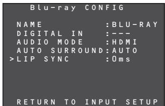
- On the INPUT SETUP OSD menu, press the / cursor buttons to select the function whose settings are to be established. When the ENTER button is now pressed, the corresponding sub-menu is displayed.
| Blu-ray CONFIG | |
| >NAME | : BLU-RAY |
| DIGITAL IN | : --- |
| AUDIO MODE | :HDMI |
| AUTO SURROUND: AUTO | |
| LIP SYNC | : Oms |
| RETURN TO INPUT SETUP | |
2-1 NAME
The names of the input functions can be changed as desired.
The maximum number of characters that can be registered for these names is 8 including spaces.
The function names that have been registered appear on the unit's display.
- Press the / cursor buttons to select NAME on the INPUT SETUP sub-menu, and press the ENTER button.
- The cursor moves to the renaming area.
| Blu-ray CONFIG | |
| >NAME | :BLU-RAY |
| DIGITAL IN | :---- |
| AUDIO MODE | :HDMI |
| AUTO SURROUND | :AUTO |
| LIP SYNC | :0ms |
| RETURN TO INPUT SETUP | |
- Press the cursor buttons to move the cursor (blinking display) to the position of the character that is to be changed.
- Press the / cursor buttons to select the character.
Any of the characters listed below can be selected to replace the existing characters. A~Z 0~9 ( ) *+, - . /
- After all the changes have been made, press the ENTER button to enter the changes.
2-2 DIGITAL IN
The DIGITAL AUDIO IN1, 2 and 3 terminals on the unit's rear panel can be allocated to the desired input functions.
(The numbers of the input terminals are allocated.)
- Press the / cursor buttons to move the cursor to DIGITAL IN on the INPUT SETUP sub-menu.
| Blu-ray CONFIG | |
| NAME | :BLU-RAY |
| > DIGITAL IN | :1 |
| AUDIO MODE | :HDMI |
| AUTO SURROUND | :AUTO |
| LIP SYNC | :0ms |
| RETURN TO INPUT SETUP | |
- Press the cursor buttons to select the digital input.
1: Optical input
2: Optical input
3: Coaxial cable input
If "_____ " is selected at this point, no digital input will be allocated.
2-3 AUDIO MODE
The audio signals (analog input, digital input, HDMI input) that are to be input to the unit are set by following the steps below.
- Press the / cursor buttons to move the cursor to AUDIO MODE on the INPUT SETUP sub-menu.
| Blu-ray CONFIG | |
| NAME | : BLU-RAY |
| DIGITAL IN | : ---- |
| >AUDIO MODE | : HDMI |
| AUTO SURROUND: AUTO | |
| LIP SYNC | : Oms |
| RETURN TO INPUT SETUP | |
- Press the cursor buttons to select the AUTO, HDMI, DIGITAL or ANALOG audio mode.
- AUTO
At this setting, the audio signals that are input to the unit are detected.
The playback signals are selected automatically in the sequence of HDMI input digital input analog input.
HDMI
At this setting, the HDMI input signals are played. Select this mode to use only HDMI signals.
Note
A function with no HDMI input (functions other than Blu-ray, GAME, DVD or DSS) cannot be set to this mode.
DIGITAL
At this setting, the digital input signals are played. Select this mode to use only digital signals.
ANALOG
At this setting, the analog input signals are played. Select this mode to use only analog signals.
Note
A function with no analog input (such as Blu-ray or GAME) cannot be set to this mode.
2-4 AUTO SURROUND
The function which automatically selects the surround mode that supports the input signals is set by following the steps below.
- Press the / cursor buttons to move the cursor to AUTO SURROUND on the INPUT SETUP sub-menu.
| Blu-ray CONFIG | |
| NAME | : BLU-RAY |
| DIGITAL IN | : --- |
| AUDIO MODE | : HDMI |
| >AUTO SURROUND | : AUTO |
| LIP SYNC | : Oms |
| RETURN TO INPUT SETUP | |
- Press the cursor buttons to select ON or OFF.
ON
At this setting, the surround mode that supports the audio signals which have been input is selected automatically, and played.
OFF
At this setting, the manual mode is established. Set the surround mode desired.
Tip
For details on the surround mode manual settings, refer to "SURROUND MODE" (page 38).
2-5 LIP SYNC
With some video components connected to the unit, there may be a time lag between the video signal processing and the audio signals. While it may be a mere time lag, it can seriously affect the enjoyment of movies or music.
The LIP.SYNC function delays the audio signals and adjusts the difference in their timing from the video signals.
The default setting is 0 ms, and adjustment up to 200 ms is possible.
- Press the / cursor buttons to move the cursor to LIP SYNC on the INPUT SETUP sub-menu.
- Press the cursor buttons to adjust the time lag.
Tip
For adjusting the time lag while monitoring the images on the display, projector or other video component, refer to "LIP.SYNC FUNCTION" (page 28).
Note
- 0 ms is set for this function in the SOURCE DIRECT mode. When the SOURCE DIRECT mode is released, the value that has been set is restored.
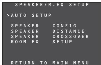
3 SPEAKER/R. EQ SETUP
After you have installed the unit connected all the components and determined the speaker layout, it is now time to perform the settings in the Speaker Setup menu for the optimum sound acoustics for your environment and speaker layout.
Before you perform the following settings, it is important that you first determine the following characteristics:
- AUTO SETUP:
"3-1 AUTO SETUP" (see page 22)
- MANUAL SETUP:
"SPEAKER COFIG" (see page 22)
"SPEAKER DISTANCE" (see page 23)
"SPEAKER CROSSOVER" (see page 23)
"ROOM EQ SETUP" (see page 23)
- Select "SPEAKER SETUP" from the MAIN MENU with or cursor buttons and press the ENTER button.
- Select the desired menu with the or cursor buttons, and press the ENTER button.
Note
After you complete this the portion of the setup, press the , , and cursor button. The cursor will move to "RETURN TO SETUP MENU" and press the ENTER button to go to the Sub-menu.
SETUP
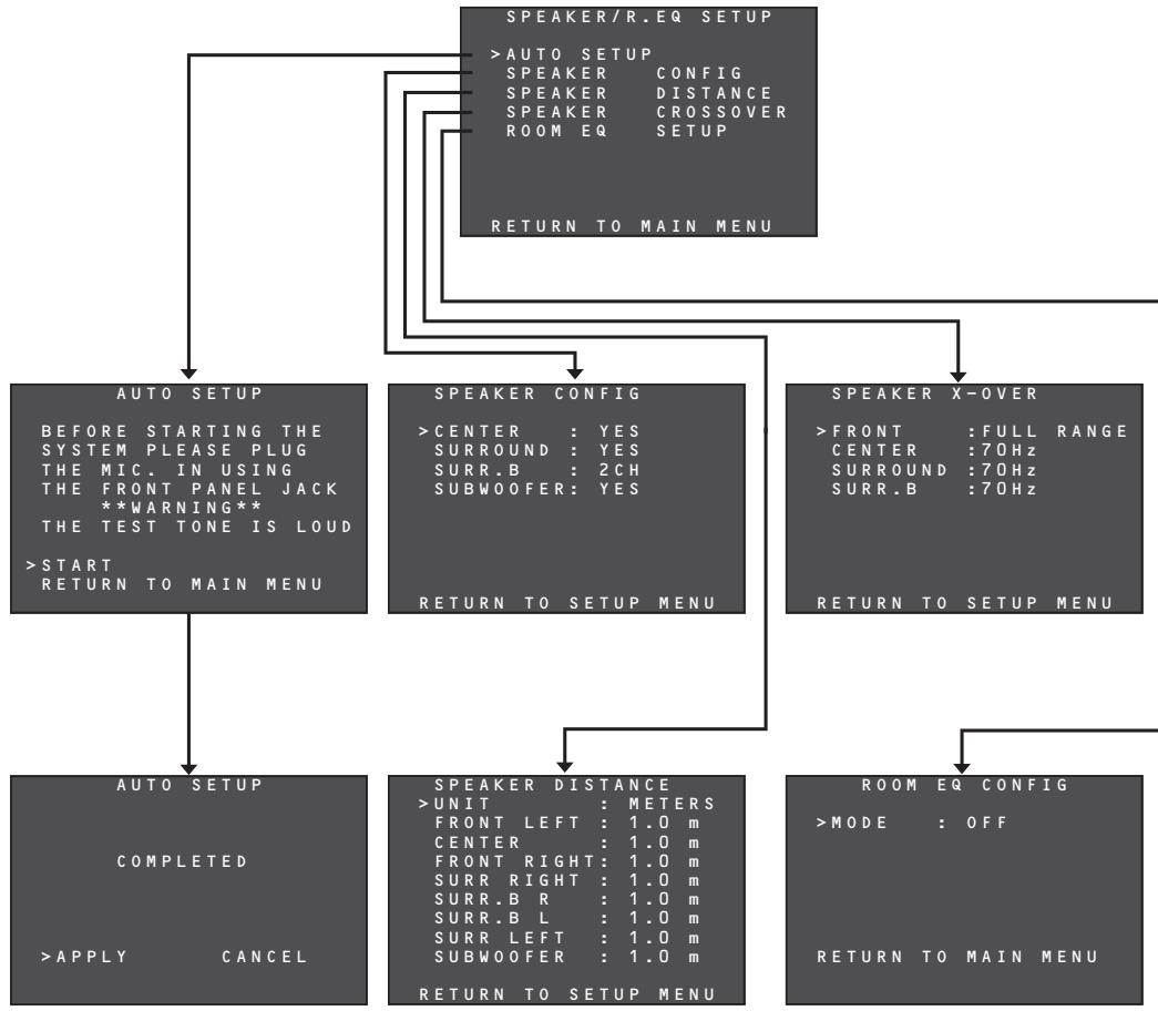
3-1 AUTO SETUP
The unit's AUTO SETUP function automatically measures the acoustic characteristics of the speaker systems and listening room where the unit is installed using the microphone provided, and sets the optimum listening environment.
HOW TO OPERATE AUTO SETUP
During the measurement process, as the current statuses will be displayed on the OSD menu screen, turn on the monitor's power.
- Connect the microphone provided to the SETUP MIC jack on the front panel.
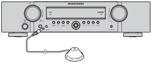
- Position the microphone at the main listening point.
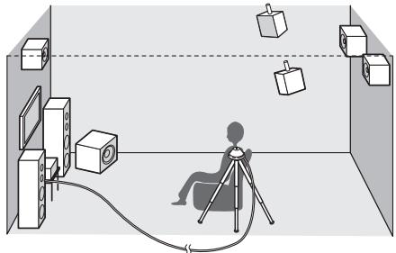
Notes
- Place the microphone at the main listening point before carrying out the measurements.
- With the microphone pointed straight up at the ceiling at the listening point, use a stand or tripod to adjust the microphone to the same height above the floor level as your ears.
- Be sure not to place any obstacles between the speakers and microphone.
-
When using a subwoofer with built-in amplifier, set the volume control to the center position, and set the crossover frequency to off or the highest frequency.
-
While the measurements are being performed, do not stand between the microphone and either speaker. Make the listening room as quiet as possible. Dark noise may adversely affect the indoor measurements. Close the windows, and turn off the power of all devices (such as cell phones, TV, radio, air conditioner, fluorescent lights, electrical appliances or dimmers).
- During the measurement process, place your cell phone at a distance from all the audio electronic devices.
Cell phones, even when they are not being used, may adversely affect the measurements due to RFI (radio frequency interference).
- We recommend that the AUTO SETUP operation be performed using the remote controller rather than the front panel controls.
- The volume levels of the test tones played from each channel will exceed the peripheral noise in the listening environment and continue to increase until the optimum signal-to-noise ratio is attained.
-
Proceed while taking the environment and any nearby children into consideration.
-
Select SPEAKER SETUP on the MAIN MENU, press the / cursor buttons to select AUTO SETUP, and press the ENTER button to display the start screen.
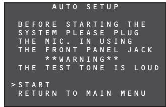
- Press the / cursor buttons to select START, and press the ENTER button to start the measurements.
When the measurements have been completed, the screen shown below will appear.
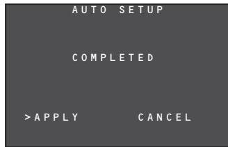
To reflect the measurement results, move the cursor to APPLY, and press the ENTER button. The results that have been set by the AUTO SETUP can be monitored on the menu setting screens shown below.
- SPEAKER CONFIG (see page 22)
- SPEAKER DISTANCE (see page 23)
- SPEAKER CROSSOVER (see page 23)
- ROOM EQ SETUP (see page 23)
- CH LEVEL SETUP (see page 24)
3-2 MANUAL SETUP
When you want to set up the system to your specifications rather than using AUTO SETUP, set the following items.
- SPEAKER CONFIG
- SPEAKER DISTANCE
- SPEAKER CROSSOVER
ROOM EQ SETUP - CH LEVEL SETUP

- Select SPEAKER SETUP from the MAIN MENU.
- Press the / cursor buttons to select an item.
- Press the ENTER button to enter what has been selected.
- Repeat steps 2 and 3 until all the settings have been selected. Then press the / cursor buttons to select RETURN TO SETUP MENU, and press the ENTER button.
SPEAKER CONFIG
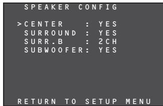
The configuration of the speakers connected to the unit is set by following the steps below.
- Press the / cursor buttons to select the speakers of each channel.
- Press the cursor buttons to set whether a speaker is to be selected (YES) or not (NO).
CENTER:
Set whether the center speaker is to be selected (YES) or not (NO).
SURROUND:
Select whether the surround left and right speakers are to be selected (YES) or not (NO).
SURR.B:
Set the surround back left and right speakers.
2CH:
Select this when using the surround back left and right speakers.
1CH:
Select this when using one surround back speaker. The audio signals will be output from the SURR.-L terminal. Check the connections.
NO:
Select this when not using both surround back left and right speakers.
SUBWOOFER:
Select whether the subwoofer is to be selected (YES) or not (NO).
- When all the settings have been selected, press the / / cursor buttons to select RETURN TO SETUP MENU, and press the ENTER button to return to the menu (SPEAKER/R.EQ SETUP).
SPEAKER DISTANCE
| SPEAKER DISTANCE | |
| >UNIT : METERS | |
| FRONT LEFT : 1.0 m | |
| CENTER : 1.0 m | |
| FRONT RIGHT : 1.0 m | |
| SURR RIGHT : 1.0 m | |
| SURR.B R : 1.0 m | |
| SURR.B L : 1.0 m | |
| SURR LEFT : 1.0 m | |
| SUBWOOFER : 1.0 m | |
| RETURN TO SETUP MENU |
The distances from the listening position to each speaker are set by following the steps below. The delay time will be calculated automatically based on these distances.
First, determine the ideal position where you usually sit in the listening room.
This is an important step for setting the acoustic timing that creates the best available sound field.
Note
-
If NO has been set on the SPEAKER CONFIG menu for a speaker, that speaker cannot be set on the SPEAKER DISTANCE menu.
-
Press the cursor buttons to set UNIT (display unit) to meters or feet.
- Press the / cursor buttons to select channels.
- Press the cursor buttons to set the distances to the speakers.
FRONT LEFT:
Set here the distance from the regular listening position to the front left speaker.
CENTER:
Set here the distance from the regular listening position to the center speaker.
FRONT RIGHT:
Set here the distance from the regular listening position to the front right speaker.
SURR RIGHT:
Set here the distance from the regular listening position to the surround right speaker.
SURR.B R:
Set here the distance from the regular listening position to the surround back right speaker.
SURR.BL:
Set here the distance from the regular listening position to the surround back left speaker.
SURR LEFT:
Set here the distance from the regular listening position to the surround left speaker.
SUBWOOFER:
Set the distance from the subwoofer to your normal listening position.
Notes
- The distances to the speakers are set in meters (METER) or feet (FEET) as below.
METERS:
The distances can be set in 0.3-meter increments from 0.0 to 9m - FEET:
The distances can be set in 1-foot increments from 0.5 to 30.0 ft.
(These distances are displayed in their approximate value on the monitor.)
- The speaker that has been set to NO is not displayed on the SPEAKER DISTANCE menu.
- If 2CH was selected as the surround back speaker setting on the SPEAKER CONFIG menu, the SURR.B L and SURR.B R settings are displayed.
-
The SURR.BACK setting is displayed if YES was selected as the surround back speaker setting on the SPEAKER CONFIG menu.
-
When all the settings have been completed, press the / cursor buttons to move the cursor to RETURN TO SETUP MENU, and press the ENTER button to return to the menu (SPEAKER/R.EQ SETUP).
SPEAKER X-OVER
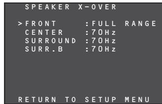
When the subwoofer is to be used, the speaker's cutoff frequency can be selected. The crossover frequency levels are selected in accordance with the sizes of the speakers by following the steps below.
The bass components below the frequency set here will be output from the subwoofer.
Sound in all frequency bands will be output from speakers with the FULL RANGE setting.
- Press the / cursor buttons to select the channels.
- Press the cursor buttons to set the crossover frequencies.
Notes
- No setting on the SPEAKER X-OVER menu is possible for a speaker if NO has been set for that speaker on the SPEAKER CONFIG menu.
-
If settings other than FULL RANGE have been selected for the front speakers while NO was set for the subwoofer on the SPEAKER CONFIG menu, ON will be automatically selected as the subwoofer setting on the SPEAKER CONFIG menu.
-
When all the settings have been completed, press the / cursor buttons to move the cursor to RETURN TO SETUP MENU, and press the ENTER button to return to the menu (SPEAKER/R.EQ SETUP).
ROOM EQ CONFIG
In order for the acoustic characteristics of the listening room measured at the AUTO SETUP stage to be adjusted to achieve the optimum environment, the frequency characteristics of all the speakers are compensated for by following the steps below.
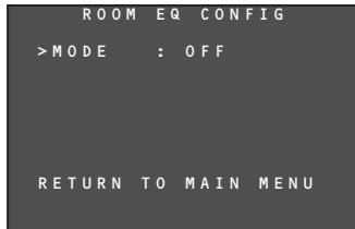
- Press the cursor buttons to set the mode.
MODE
ON:
The frequency characteristics are compensated for.
OFF:
The frequency characteristics are not compensated for.
- When all the settings have been completed, press the / cursor buttons to move the cursor to RETURN TO MAIN MENU, and press the ENTER button to return to the menu (SPEAKER/R.EQ SETUP).
SETUP
4. CH LEVEL SETUP
Each channel level can be adjusted to suit the program source played as well as your own preferences.
A maximum of two channel levels that have been adjusted can be stored in the unit's memory.
4-1 MEMORY MODE
The channel level settings can be stored in the memory and the stored settings can be called by following the steps below.
- Press the / cursor buttons to move the cursor to MODE on the CH LEVEL SETUP menu.
| CH LEVEL SETUP | |
| >MODE: CALIBRATE | |
| FRONT LEFT : 0dB | |
| CENTER : 0dB | |
| FRONT RIGHT : 0dB | |
| SURRRight : 0dB | |
| SURR_B RIGHT : 0dB | |
| SURR_B LEFT : 0dB | |
| SURR_LEFT : 0dB | |
| SUBWOOFER : 0dB | |
| LFE LEVEL SETUP | |
| RETURN TO MAIN MENU |
- Press the cursor buttons to select CALIBRATE, AUTO, REFERENCE 1 or REFERENCE 2 as the memory mode.
CALIBRATE:
Each channel level that has been set is displayed.
In this state, the channel levels that you want to change can be changed.
For details on the level adjustments, refer to "4-2 ADJUSTING THE CHANNEL LEVELS."
AUTO:
The channel levels automatically set by the AUTO SETUP function are displayed.
(For details on AUTO SETUP, refer to page 22.)
In this state, the channel levels that you want to change can be changed.
For details on the level adjustments, refer to "4-2 ADJUSTING THE CHANNEL LEVELS."
REFFERENCE 1, REFFERENCE 2:
The settings stored in the memory by the user can be called.
For details on storing the channel levels in the memory, refer to "4-4 STORING THE CHANNEL LEVELS IN THE MEMORY."
4-2 ADJUSTING THE CHANNEL LEVELS
Each channel level is adjusted by following the steps below.
- Press the / cursor buttons to move the cursor to the channel on the CH LEVEL SETUP menu whose level is to be adjusted.
| CH LEVEL SETUP | |
| MODE: CALIBRATE | |
| FRONT LEFT : 0dB | |
| >CENTER : 0dB | |
| FRONT RIGHT : 0dB | |
| SURRRight : 0dB | |
| SURR_B RIGHT : 0dB | |
| SURR_B LEFT : 0dB | |
| SURR_LEFT : 0dB | |
| SUBWOOFER : 0dB | |
| LFE LEVEL SETUP | |
| RETURN TO MAIN MENU |
-
Press the cursor buttons to adjust the volume level.
-
Adjust the volume from all the speakers to the same level.
Each channel can be adjusted to any level in the range from -15 dB to +15 dB. -
Repeat steps 1 and 2 to adjust the levels of all the channels.
4-3 LFE LEVEL SETUP
The output level of the LFE signals included in the Dolby Digital signals or DTS signals can be adjusted by following the steps below.
- Press the / cursor buttons to move the cursor to LFE LEVEL SETUP on the CH LEVEL SETUP menu.
| CH LEVEL SETUP | |
| MODE: CALIBRATE | |
| FRONT LEFT : 0dB | |
| CENTER : 0dB | |
| FRONT RIGHT : 0dB | |
| SURRRight : 0dB | |
| SURR.B RIGHT : 0dB | |
| SURR.B LEFT : 0dB | |
| SURR.Left : 0dB | |
| SUBWOOFER : 0dB | |
| >LFLEVEL SETUP | |
| RETURN TO MAIN MENU |
- If the ENTER button is now pressed, a submenu will appear.
| L FE | LE VEL | SETUP | |
| >DOLBY | : 0 dB | ||
| DTS | : 0 dB | ||
| RETURN TO | SETUP | MENU | |
- Press the / cursor buttons to select the DOLBY or DTS signals, and press the / cursor buttons to adjust their levels.
- The LFE signals can be adjusted to any level within the range from 0 dB to -10 dB.
- When all the level adjustments have been completed, press the / cursor buttons to move the cursor to RETURN TO SETUP MENU, and press the ENTER button to return to the CH LEVEL SETUP menu.
| L FE | LEVEL | SETUP |
| D O L B Y | : 0 dB | |
| D T S | : 0 dB | |
| >RETURN TO | SETUP | MENU |
4-4 STORING THE CHANNEL LEVELS IN THE MEMORY
Each channel level that has been adjusted can be stored in the memory, whether in memory mode REFERENCE 1 or memory mode REFERENCE 2.
- When the adjustment of all the channel levels has been completed, press the ENTER button on the CH LEVEL SETUP menu.
Note
If the cursor is now moved to LFE LEVEL SETUP, a sub-menu appears. Move the cursor to a position other than LFE LEVEL SETUP.
| CH LEVEL SETUP | |
| MODE: CALIBRATE | |
| >FRONT LEFT : 2dB | |
| CENTER : 1dB | |
| FRONT RIGHT : 2dB | |
| SURRRight : -1dB | |
| SURR.B RIGHT : 0dB | |
| SURR.B LEFT : 0dB | |
| SURR.Left : -1dB | |
| SUBWOOFER : 3dB | |
| LFE LEVEL SETUP | |
| RETURN TO MAIN MENU |
- Move the cursor to MODE, and highlight REFERENCE 1 for memory mode.
| CH LEVEL SETUP | |
| >MODE: | REFERENCE1 |
| FRONT LEFT : | 2 dB |
| CENTER : | 1 dB |
| FRONT RIGHT : | 2 dB |
| SURR-right : | -1 dB |
| SURR_B RIGHT : | 0 dB |
| SURR_B LEFT : | 0 dB |
| SURR_LEFT : | -1 dB |
| SUBWOOFER : | 3 dB |
| LFE_LEVEL | SETUP |
| RETURN TO MAIN | MEN |
- Press the cursor buttons to select REFERENCE 1 or REFERENCE 2, and press the ENTER button to store the settings in the memory.
- When all the settings have been completed, press the / cursor buttons to move the cursor to RETURN TO MAIN MENU, and press the ENTER button to return to MAIN MENU.
| CH LEVEL SETUP | |
| MODE: | REFERENCE1 |
| FRONT LEFT : | 2dB |
| CENTER : | 1dB |
| FRONT RIGHT : | 2dB |
| SURRRight : | -1dB |
| SURR_B RIGHT : | 0dB |
| SURR_B LEFT : | 0dB |
| SURR_LEFT : | -1dB |
| SUBWOOFER : | 3dB |
| LFE LEVEL SETUP | |
| >RETURN TO MAIN MENU | |
5. SOUND PARAMETER
The NIGHT mode, the Dolby PLII MUSIC and NEO:6 PARAMETER are set by following the steps below.
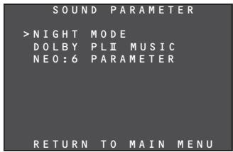
5-1 NIGHT MODE
In the NIGHT mode, the dynamic range of the sound played is reduced, making it possible to listen more clearly to a softer sound while keeping the overall volume level relatively low at night or in similar circumstances. This mode works only with Dolby digital sound.
- Press the / cursor buttons to move the cursor to NIGHT MODE on the SOUND PARAMETER menu, and when the selection is entered using the ENTER button, a submenu appears.
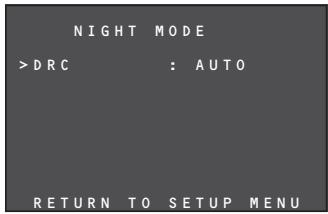
-
Press the cursor buttons to set AUTO or set the compression rate from 0.0 to 1.0.
-
When AUTO is set, the signals contained in the Dolby TrueHD software are detected, and the NIGHT mode is automatically activated. The NIGHT mode is deactivated with any Dolby digital sound signals that are not Dolby TrueHD signals.
- When the compression rate is set to 0.0, the NIGHT mode function is deactivated.
-
When the NIGHT mode is activated, the parameter is set in 0.1-step increments from 0.1 (low) to 1.0 (high).
-
When all the settings have been completed, press the / cursor buttons to move the cursor to RETURN TO SETUP MENU, and press the ENTER button to return to SOUND PARAMETER menu.
The Dolby PLII MUSIC mode creates an environment for playing CDs and other stereo sources in which the listener is enveloped by a full and rich sound.
- Press the / cursor buttons to move the cursor to DOLBY PLII MUSIC on the SOUND PARAMETER menu, and when the selection is entered using the ENTER button, a sub-menu appears.
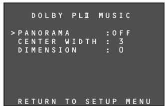
PANorama:
In the PANorama mode, the sound delivered from the front left and right speakers envelops the listener to create a 3-dimensional sound space.
Press the cursor buttons to set the PANorama mode to ON or OFF.
CENTERWIDTH:
This function gradually assigns the center channel components to the front left and right speakers. By assigning them in this way, inconsistencies in the tone colors between the speakers can be smoothed out.
Adjustment in eight steps from 0 to 7 is possible using the cursor buttons.
This setting cannot be selected if NO has been selected as the center speaker setting.
DIMENSION:
The DIMENSION function is used to adjust level differences between the front and rear. Depending on the input source, some sound is heard more strongly at the front and others more strongly at the rear. When this function is used, the desired balance can be achieved.
Adjustment in seven steps from -3 to 3 is possible using the cursor buttons.
- When all the settings have been completed, press the / cursor buttons to move the cursor to RETURN TO SETUP MENU, and press the ENTER button to return to the SOUND PARAMETER menu.
5-3 NEO:6 PARAMETER
The DTS NEO:6 mode allows the sound of up to 6.1 channels to be output when 2-channel sound has been input. (It also supports the input of 5.1-channel sound.)
In this mode, the sound images of the center speaker are expanded.
- Press the / cursor buttons to select NEO:6 PARAMETER.
- Press the ENTER button to enter the selection.
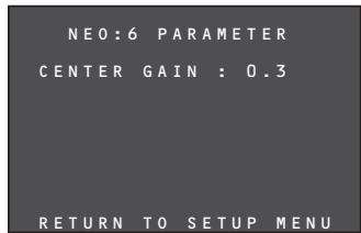
- The CENTER GAIN level can be selected in 0.1 increments from 0.0 to 1.0 using the cursor buttons.
Notes
- This setting takes effect only in the NEO:6 MUSIC mode.
- When all the settings have been completed, press the / cursor buttons to move the cursor to RETURN TO SETUP MENU, and press the ENTER button.
ADVANCED OPERATION
AMP OPERATION
USING THE SLEEP TIMER
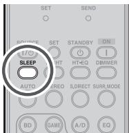
To program this unit for automatic standby, press the SLEEP button on the remote controller.
Each press of the button will increase the time before shut down in the following sequence.
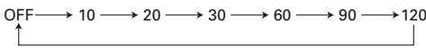
The sleep time will be shown for a few seconds in the display on the front panel, and it will count down until the time has elapsed.
When the programmed sleep time has elapsed, the unit will automatically turn off.
Note that the indicator on the display will illuminate when the Sleep function is programmed.
To cancel the sleep function, repeatedly press the SLEEP button on the remote controller until the timer time is cleared. When it is canceled, the * indicator on the display goes off.
DISPLAY MODE
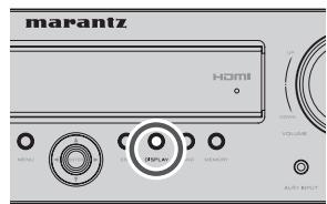
You can select the display mode for the front display of the unit.
To select this mode, press the DISPLAY on the remote controller or the front panel.
When this button is pressed, the display mode is switched in the following sequence.
Input function Volume Surround Input signals Input function
Input function:
The status of the input function that was set in FUNCTION INPUT SETUP (see page 20) is displayed.
Volume:
The current volume level is displayed.
Surround:
The status of the selected surround mode is displayed.
Input signals:
The status of the signals that have been input to the selected function is displayed.
DIMMER
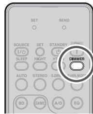
When this button is pressed once, the display is dimmed.
When this button is pressed twice, the display is turned off and the indicator lights up.
Press this button again to turn the display on again.
Note
- In the display off status, only the indication on the unit's display illuminates to indicate that this function is operational.
RECORDING AN ANALOG SOURCE
In normal operation, the audio or video source selected for listening through this unit is sent to the record outputs.
This means that any program you are watching or listening to may be recorded simply by placing machines connected to the outputs for VCR OUT in the record mode.
To record the input source signal you are currently watching or listening to
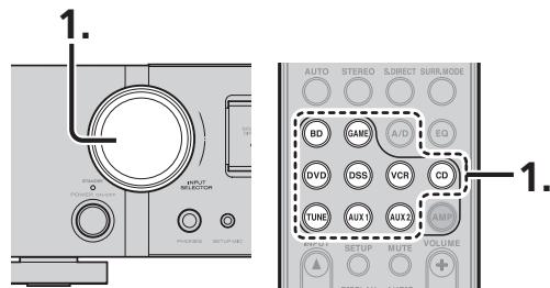
- Select the input source to record by turning the INPUT SELECTOR knob on the front panel or simply press the input selector buttons on the remote controller.
The input source is now selected and you may watch or listen to it as desired. - The currently selected input source signal is output to the VCR OUT outputs for recording.
- Start recording to the recording component as desired.
Notes
- When connecting only digital signal input, output cannot be made to the VCR OUT terminals. When using recording functions, be sure to also make connections for analog signal input.
- No conversion is made from component video signal input to Video signal output. Always use the same signal type for both input and output.
- Video or audio signals input to HDMI input terminals cannot be recorded.
SELECTING ANALOG AUDIO INPUT OR DIGITAL AUDIO INPUT
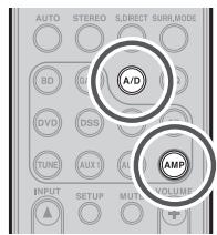
If you have already assigned the digital inputs, you can temporarily select the audio input mode for each input source as following procedures.
Press the AMP button and press the A/D button.
When this button is pressed, the input mode is switched in the following sequence.
Auto HDMI Digital Analog Auto
Auto mode:
The types of signals being input to the digital and analog input jacks for the selected input source are detected automatically.
If no digital signal is being input, the analog input jacks are selected automatically.
HDMI mode:
HDMI mode can be selected only when an HDMI input has been assigned as an input source.
When "HDMI AUDIO" under PREFERENCE of the SETUP MENU is set to "THROUGH", the HDMI mode cannot be selected.
Digital mode:
The input signal is fixed to an assigned digital input terminal.
Analog mode:
The analog input jacks are selected.
To select the Auto surround mode during playback, press the AUTO button on the front panel.
(Using the remote controller)
To select the Auto surround mode, press the AMP button and press the AUTO button.
- For surround modes, see "Surround Mode" on page 38.
NIGHT MODE
In the NIGHT mode, the dynamic range of the sound played is reduced, making it possible to listen more clearly to a softer sound while keeping the overall volume level relatively low at night or in similar circumstances.
This mode works only with Dolby digital sound.
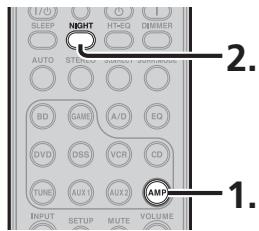
- Press the AMP button on the remote controller.
- Each time the NIGHT button is pressed, the NIGHT mode value changes as below.
AUTO 0.0 0.1 0.2 1.0 AUTO
The value represents the dynamic range level.
- When the NIGHT mode is set to 0.0, it is deactivated; when set to 1.0, it is at the maximum.
- When the NIGHT mode is set to AUTO, the signals contained in the Dolby TrueHD software are detected, and the NIGHT mode is automatically activated.
- The NIGHT mode is deactivated with any Dolby digital sound signals which are not Dolby TrueHD signals.
- When the SOURCE DIRECT mode has been selected, the NIGHT mode is deactivated.
ADJUSTING THE DIFFERENCE IN THE VOLUME LEVELS BETWEEN SPEAKERS (WITH TEST TONES)
Test tones can be output from each speaker, and any difference in the volume levels between speakers can be adjusted.
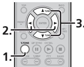
- Press the T.TONE button on the remote controller.
The test tones are output for 2 seconds each for each channel in the following sequence which is repeated: Front left center front right surround right surround back right surround back left surround left subwoofer front left ...
- The test tone will not be output for a speaker if NO has been set for that speaker on the SPEAKER CONFIG menu.
- Press the cursor buttons to adjust the volume level of the speaker.
- Press the / cursor buttons to select the speaker from which to output the test tone.
- Repeat steps 2 and 3, and adjust the volume level of the test tone that is output from each speaker until the level for all the speakers is the same.
REGISTERING THE SPEAKER VOLUME LEVEL SETTING
Up to two volume levels that have been set as desired can be stored in the memory.
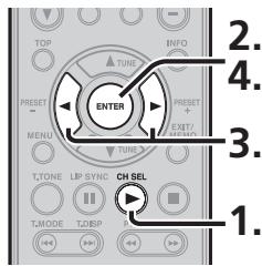
- Press the CH SEL button on the remote controller.
- Press the ENTER button. "REF-1" blinks for several seconds on the monitor and display.
- Press the cursor buttons to switch the storage location from REF1 to REF2 or vice versa, and press the ENTER button.
- Press the ENTER button to store the current volume level setting.
CALLING REGISTERED SPEAKER VOLUME LEVEL SETTINGS
The volume level settings that have been registered can be called.
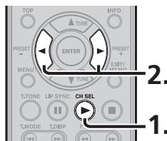
- Press the CH SEL button on the remote controller.
- Each time the cursor buttons are pressed, the volume level setting is switched between AUTO, REF1 and REF2.
Tip
- When AUTO is selected, the speaker level that was set automatically by AUTO SETUP is called.
For details on AUTO SETUP, see page 22.
ADVANCED OPERATION
ADJUSTING DIFFERENCES IN VOLUME LEVELS BETWEEN SPEAKERS (WITHOUT TEST TONES)
Differences in the volume levels between speakers can be adjusted without using test tones.
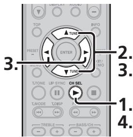
- Press the CH SEL button on the remote controller.
-
Each time the / cursor buttons are pressed, the display changes in the following sequence.
CAL (or AUTO, REF1, REF2) FL C FR SR (SBR SBL) or SB SL SUB CAL (or AUTO, REF1, REF2) -
There is no display for a speaker if NO has been set for that speaker on the SPEAKER CONFIG menu.
- Press the cursor buttons to adjust the volume level of the speaker displayed. When the button is pressed, the volume level is increased; conversely, when the button is pressed, it is reduced.
- When the level adjustments for all the speakers have been completed, press the CH.SEL button to exit the settings.
LISTENING THROUGH HEADPHONES
This jack may be used to listen to the unit's output through a pair of headphones. Be certain that the headphones have a standard 1/4'' stereo phono plug.
Note that the speakers will automatically be turned off when the headphone jack is in use.
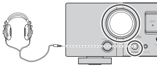
Note
The surround mode returns to the previous setting as soon as the headphone plug is removed from the jack.
HT-EQ
The remote controller is used for the HT-EQ setting.
For details on the HT-EQ function, see page 19.
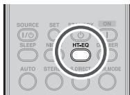
- Press the HT-EQ button on the remote controller.
- Each time the HT-EQ button is pressed, the function is switched between OFF and ON.
ON: The HT-EQ function is used.
OFF: The HT-EQ function is not used.
ROOM EQ
The ROOM EQ (room equalizer) function for compensating for the acoustic characteristics of the listening room that was measured by the AUTO SETUP function is set to ON or OFF.
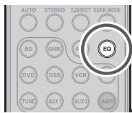
For details on AUTO SETUP, see page 22.
- Press the EQ button on the remote controller.
- Each time the EQ button is pressed, the function is switched between OFF and ON. ON: The ROOM EQ function is used. OFF: The ROOM EQ function is not used.
LIP.SYNC FUNCTION
The LIP.SYNC function adjusts the difference in the timing between the video signals and audio signals by delaying the audio signals before outputting them.
For details on LIP.SYNC, see page 21.
- Press the LIP.SYNC button on the remote controller.
- Each time the LIPSYNC button is pressed, the difference in the timing can be adjusted in 10-ms increments using the cursor buttons.
The default setting is 0 ms, and adjustment up to 200 ms is possible.
Perform the adjustment while monitoring the images on the display, projector or other video component.
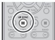
Note
This function is deactivated (0 ms) in the SOURCE DIRECT mode. When the SOURCE DIRECT mode is released, the value that has been set is restored.
BILINGUAL FUNCTION
When the input source contains Dolby or DTS bilingual sound, this function enables selection of the sound to be played.
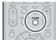
- Press the AUDIO button on the remote controller.
- Each time the AUDIO button is pressed, the audio mode is switched.
MAIN:
BIL MAIN
The sound of the main channel (left) is played.
SUB:
BIL SUB
The sound of the sub-channel (right) is played.
MAIN + Sub:
BIL M+S
The sound of the main and sub-channels is played.
VIDEO CONVERT FUNCTION
The unit is equipped with a video convert function which outputs analog video input (video input or component video input) signals to HDMI.
This means that these signals can be viewed simply by connecting one HDMI cable between the unit's HDMI OUT terminal and monitor regardless of the method used to connect the player and the unit's VIDEO terminals or COMPONENT VIDEO terminals.
(For the setting procedure, see page 19.)
Notes
- With this function, the media may not be properly played in the still, fast forward, reverse play and other modes.
- With the video-convert function, out-of-sync or other types of trouble may arise depending on the TV, projector or component used. In such cases, deactivate the video-convert function.
EXAMPLES OF CONNECTIONS
- When the monitor has been connected to the unit's HDMI OUT terminal
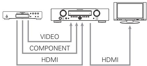
Note
-
The signals up-converted to HDMI output signals are output without any processing at the resolution of the analog video signals that were input. When up-converting video or component video signals with a 480i resolution, a video monitor (TV set) supporting the 480i resolution must be connected to the unit.
-
When the monitor has been connected to the unit's VIDEO MONITOR OUT terminal
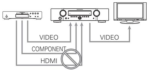
Note
- The HDMI video signals and component video signals that are input from the player are not output from the unit'sVIDEO MONITOR OUT terminal.
- When the monitor has been connected to the unit's COMPONENTVIDEO MONITOR OUT terminal
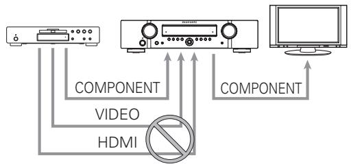
Note
- The HDMI video signals and video signals that are input from the player are not output from the unit's COMPONENT MONITOR OUT terminal.
TUNER OPERATIONS (PRESET MEMORY)
With this unit, up to 30 FM and AM broadcast stations can be preset in the sequence desired. For each of these stations, the frequency and reception mode can be stored in the memory as needed.
AUTO PRESET MEMORY
This function makes it possible to scan the FM band automatically and store all stations with suitable signal strength in the unit's preset memories.
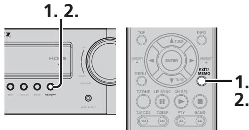
- Hold down the unit's MEMORY button or the EXIT/MEMO button on the remote controller for at least two seconds.
"AUTO MEM" appears on the display, and scanning starts from the lowest frequency. - Scanning automatically stops when all 30 preset memories have been set or when auto scanning has reached the uppermost limit of the band.
To stop the auto preset memory operation at any time, press the unit's MEMORY button or the EXIT/MEMO button on the remote controller.
Note
The auto preset cannot be performed for AM stations. Perform the manual preset instead.
MANUAL PRESET MEMORY
(When performing the operations using the unit's controls)
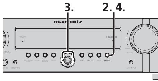
- Tune into the frequency of the broadcast station to be set.
(Refer to the section on "MANUAL TUNING" or "AUTO TUNING".) - Press the unit's MEMORY button. The MEM indicator starts blinking on the display.
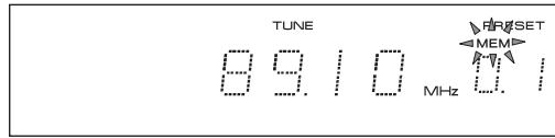
- While the MEM indicator is still blinking, press the cursor buttons to select the preset number.
- Press the MEMORY button again to enter the selection.
The indicator stops blinking, and the broadcast station is stored in the preset memory selected.
(When performing the operations using the remote controller)
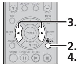
- Tune into the frequency of the broadcast station to be set.
(Refer to the section on "MANUAL TUNING" or "AUTO TUNING".)
ADVANCED OPERATION
- Press the EXIT/MEMO button on the remote controller. The MEM indicator starts blinking on the display.

- While the MEM indicator is still blinking, press the cursor buttons to select the preset number.
- Press the EXIT/MEMO button again to enter the selection.
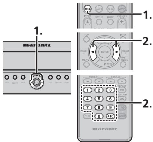
CALLING PRESET STATIONS
(When performing the operations using the unit's controls)
- Press the unit's cursor buttons to select the preset station to be called.
(When performing the operations using the remote controller) - Press the TUNE button on the remote controller twice in succession.
- Press the cursor buttons to select the preset station whose programs are to be heard.
Alternatively, press the numeric buttons to select the preset station.
Now in use in many countries, RDS (Radio Data System) is a description of the station's programming hidden space in the FM signal.
Your new unit is equipped with RDS to assist in the selection of FM stations using station and network names, rather than broadcast frequencies. Additional RDS functions include the ability to search for programme types.
RADIO TEXT
Some RDS stations broadcast RADIO TEXT, which is additional information on the station and programme being broadcast.
RADIO TEXT information appears as 'running' text in the display. RADIO TEXT is transmitted character by the radio station. As a result of that it may take some time until the entire text has been completely received.
RDS DISPLAY
When a unit is tuned to an FM station that is transmitting RDS data, the Front Panel Information Display will automatically show the station name or RDS TEXT in place of the typical display of the station's broadcast frequency.
To change the display, press the TUNE button and press the T.DISP button on the remote controller or the DISPLAY button on the unit.
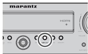
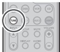
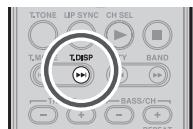
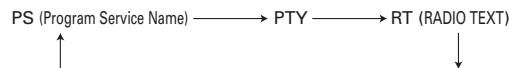
Frequency Volume Surround mode Signal Input
PTY SEARCH
Your unit is equipped to automatically search for stations transmitting any of 29 different programme types. To search for a PTY, follow these procedures:
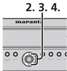
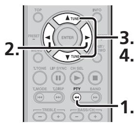
- Press the PTY button in the TUNER MODE on the remote controller. The current station's PTY will be displayed, or the currently selected PTY group will be displayed in blinking if no station or RDS data is present.
- To change to a new PTY type, press the TUNE or button on the front panel or press the or button on the remote controller until the desired PTY is shown in the display.
- Once the desired PTY group or type has been selected, press the or button on the front panel or press the or button on the remote controller. The PTY Auto search will start, and the tuner will pause at each station broadcasting RDS PTY information corresponding to the selected choice.
- To advance to the next RDS station with the desired PTY, press the or button on again
| NUMBER | DISPLAY | PROGRAMME TYPE |
| 1 | POP M | Pop Music |
| 2 | ROCK M | Rock Music |
| 3 | EASY M | M. O. R. Music |
| 4 | LIGHT M | Light classical |
| 5 | CLASSICS | Serious classical |
| 6 | OTHER M | Other Music |
| 7 | WEATHER | Weather |
| 8 | FINANCE | Finance |
| 9 | CHILDREN | Children's programmes |
| 10 | SOCIAL | Social Affairs |
| 11 | RELIGION | Religion |
| 12 | PHONE IN | Phone In |
| 13 | TRAVEL | Travel |
| 14 | LEISURE | Hobbies |
| 15 | JAZZ | Jazz Music |
| 16 | COUNTRY | Country Music |
| 17 | NATION M | National Music |
| 18 | OLDIES | Oldies Music |
| 19 | FOLK M | Folk Music |
| 20 | DOCUMENT | Documentary |
| 21 | NEWS | News |
| 22 | AFFAIRS | Current Affairs |
| 23 | INFO | Information |
| 24 | SPORT | Sport |
| 25 | EDUCATE | Education |
| 26 | DRAMA | Drama |
| 27 | CULTURE | Culture |
| 28 | SCIENCE | Science |
| 29 | VARIED | Varied |
This remote controller is preset with a total of 10 types of remote codes, including Marantz BD (Blu-ray), GAME, DVD, VCR (VCR deck), DSS (satellite broadcasting tuner), TUNER, CD, AUX1, AUX2, and AMP (amplifier).
1. Press the SOURCE button.
For this example, press DVD.
Pressing the SOURCE button once changes the remote control to the settings for the source that was pressed.
To change the amplifier on other source, press the SOURCE button twice (double-click). The code is sent, and then the amplifier source changes to DVD.
PRESET MODE
WHEN OPERATING NON-MARANTZ AV
EQUIPMENTPRODUCTS
This remote controller is preset with remote control codes from AV equipment by other manufacturers. The preset codes are TV, CD, DVD, BD and DSS. Settings can be made in one of two ways.
When the preset codes are set, the following codes are contained in the source button of the remote controller.
See the attached manufacturer number list for the preset manufacturers, devices, preset numbers, and other settings.
| Remote controller source name | Corresponding preset code | Device name |
| TV | TV | Television |
| BD | ||
| DVD | DVD | DVD player |
| CD | CD | CD player |
| DSS | SATELLITE | Satellite broadcasting tuning equipment |
Importants
- Some codes may be not match your equipment.
- The preset codes do not cover full functions.
- When the batteries are getting weak, the preset procedure is not successful.
PROGRAMMING WITH THE 4-DIGIT CODE
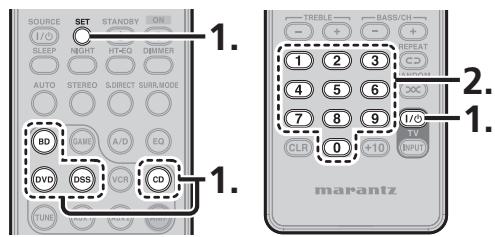
-
Press and hold down the SOURCE button for the appliance which should be controlled and press SET button until the SEND indicator blinks twice. Then SET indicator flashes. In case of TV, press and hold down the TV Power On/off button and SET button.
-
Press the 4-digit code by numeric buttons for appliance (code table at the end of this book) When the procedure is successful, the SEND indicator will blink twice.
Note
If the indicator did not blink twice, then repeat steps 1 through 2 and try entering the same code again.
SCANNING THE CODE TABLE
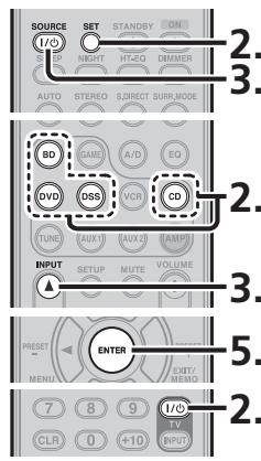
- Switch on the appliance which should be controlled.
- Press and hold down the SOURCE button for appliance which should be controlled and press SET button until the SEND indicator blinking twice. Then SET indicator flashes. In case of TV, press and hold down the TV Power On/off button and SET button.
- Aim the remote control at the appliance and slowly alternate between pressing INPUT button and the SOURCE ON/OFF button for the appliance. In case of TV, press INPUT button and the TV Power On/off button alternately.
- Stop when the appliance turns off.
- Press ENTER button once to lock in the code.
CHECKING THE CODE
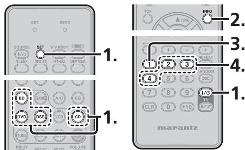
- Press and hold down the SOURCE button for appliance which should be controlled and press SET button until the SEND indicator blinking twice then SET indicator flashes.
In case of TV, press and hold down the TV Power On/off button and SET button.
- Press the INFO button.
The SEND indicator will blink twice.
- To view the code for first digit, press 1 once.
Wait 3 seconds, count the SEND indicator blinks (e.g. 3 blinks = 3) and write down the number.
Note
If a code digit is "0", the SEND indicator will not blink.
- Repeat step 3 three more times for remaining digits. Use 2 for the second digit, 3 for the third digit, and 4 for the fourth digit.
RESETTING THE CODE
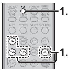
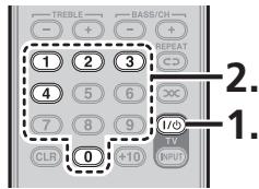
- Press and hold down the SOURCE button for appliance which should be controlled and press SET button until the SEND indicator blinking twice.
Then SET indicator flashes.
In case of TV, press and hold down the TV Power On/off button and SET button.
- Press the below codes to reset.
TV :1000
DVD:2000
CD :3000
DSS:4000
BD :5000
The indicator will blink twice.
Note
After this procedure, the selected SOURCE button is set initial code.
ADVANCED OPERATION
CONTROLLING MARANTZ COMPONENTS
- Press the desired SOURCE button.
-
Press the desired operation buttons to play the selected component.
-
For details, refer to the component's user guide.
- It may not be possible to operate some models.
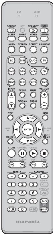
BLU-RAY DISC MODE
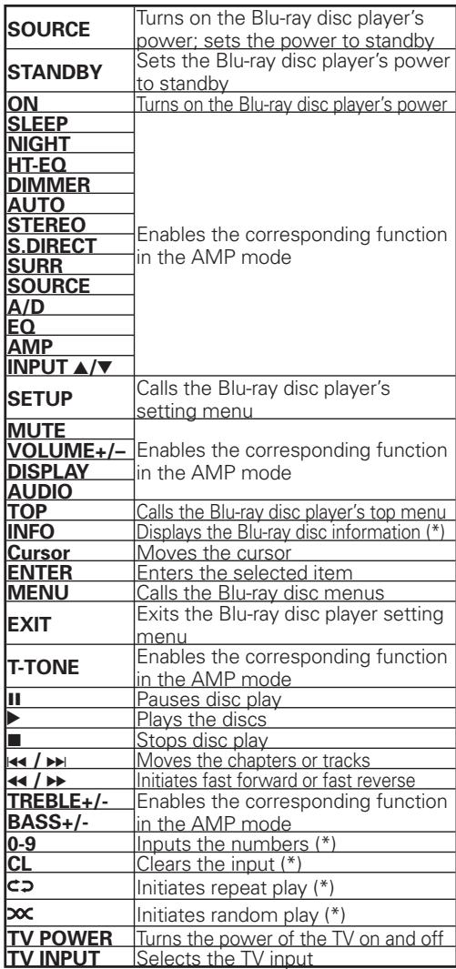
(*) The preset code libraries of products made by other manufacturers are not provided for these buttons.
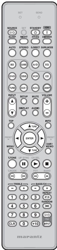
DVD MODE
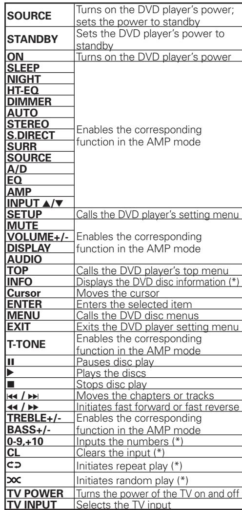
(*) The preset code libraries of products made by other manufacturers are not provided for these buttons.
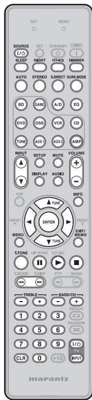
DSS MODE
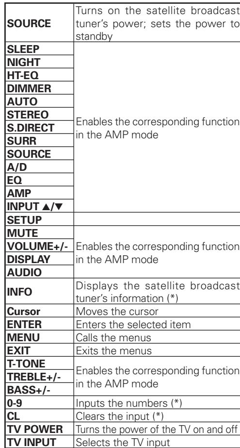
(*) The preset code libraries of products made by other manufacturers are not provided for these buttons.
CD MODE
| SET | SEND | ||
| ○ | ○ | ○ | ○ |
| SOURCE | SET | STANDBY | ON |
| I/O | ○ | ○ | I |
| BEEP | NIGHT | HT-EO | DBIMER |
| AUTO | STEREO | SIRECT | SURE_MODE |
| BD | GAMP | A/D | EQ |
| DVD | DSS | VCR | CD |
| TUNE | AUX1 | AUX2 | AMP |
| INPUT | SETUP | MUTE | VOLUME |
| TOP | DISPLAY | AUDIO | + |
| TOP | TUNE | ○ | |
| PRESET | ENTER | PRESET | + |
| MENU | TUNE | EXT1/EXT2 | |
| TONE | LP SYNC CH SEL | ||
| T MODE | TO ESP | PTY | BAND |
| TREBLE | ← | → | |
| MARANTZ | |||
| SOURCE | Turns on the CD player's power; sets the power to standby |
| STANDBY | Sets the CD player's power to standby |
| ON | Turns on the CD player's power |
| SLEEP | Enables the corresponding function in the AMP mode |
| NIGHT | |
| HT-EQ | |
| DIMMER | |
| AUTO | |
| STEREO | |
| S.DIRECT | |
| SURR | |
| SOURCE | |
| A/D | |
| EQ | |
| AMP | |
| INPUT ▲/▼ | |
| MUTE | |
| VOLUME+/- | |
| DISPLAY | |
| AUDIO | |
| ENTER | Enters the selected items |
| MENU | Calls the menus |
| T-TONE | Enables the corresponding function in the AMP mode |
| II | Pauses disc play |
| ▷ | Plays the discs |
| ■ | Stops disc play |
| ← / → | Moves the chapters or tracks |
| ← / → | Initiates fast forward or fast reverse |
| TREBLE+/- | Enables the corresponding function in the AMP mode |
| BASS+/- | |
| 0-9,+10 | Inputs the numbers (*) |
| CL | Cleared the input (*) |
| CD | Initiates repeat play (*) |
| ×× | Initiates random play (*) |
| TV POWER | Turns the power of the TV on and off |
| TV INPUT | Selects the TV input |
(*) The preset code libraries of products made by other manufacturers are not provided for these buttons.
AUX2 MODE
| SET | SEND | ||
| ○ | ○ | ||
| SOURCE | SET | STANDBY | ON |
| I/O | I | ||
| SLEEP | NIGHT | H-TEQ | DIMMER |
| AUTO | STEREO | S-IRECT | SUM-MODE |
| BD | GAMD | A/D | CO |
| DVD | DSS | VCR | CD |
| TUNE | AUX1 | AUX2 | AMP |
| INPUT | SETUP | MUTE | VOLUME |
| + | |||
| YOP | - | ||
| TUNE | |||
| PRESENT | ENTER | PHSET+ | |
| MENU | TUNE | EXT/MELO | |
| TONE | LP SYNC | CH SEL | |
| TAGODE | TO-BP | PTY | BAND |
| TREBLLE | BASS/CH- | ||
| + | |||
| 1 | 2 | 3 | REPEAT |
| 4 | 5 | 6 | RANDOM |
| 7 | 8 | 9 | I/O |
| CLR | 0 | <10 | TV |
| INPUT | |||
| marantz | |||
| SOURCE | Turns on the universal dock's power; sets the power to standby |
| STANDBY | Sets the universal dock's power to standby |
| ON | Turns on the universal dock's power |
| SLEEP | Enables the corresponding function in the AMP mode |
| NIGHT | |
| HT-EQ | |
| DIMMER | |
| AUTO | |
| STEREO | |
| S.DIRECT | |
| SURR | |
| SOURCE | |
| A/D | |
| EQ | |
| AMP | |
| INPUT▲/▼ | |
| SETUP | Changes the user interface |
| MUTE | Enables the corresponding function in the AMP mode |
| VOLUME+/- | |
| DISPLAY | |
| AUDIO | |
| Cursor | Moves the cursor |
| ENTER | Enters the selected items |
| MENU | Calls the menus |
| T-TONE | Enables the corresponding function in the AMP mode |
| II | Pauses play |
| ▶ | Initiates play |
| ■ | Stops play |
| ←/→ | Moves the chapters or tracks |
| ←/→ | Initiates fast forward or fast reverse |
| TREBLE+/- | Enables the corresponding function in the AMP mode |
| BASS+/- | |
| 0-9 | Inputs the numbers (*) |
| CL | Cleared the input (*) |
| ⊂ | Initiates repeat play (*) |
| ×× | Initiates random play (*) |
| TV POWER | Turns the power of the TV on and off |
| TV INPUT | Selects the TV input |
(*) The preset code libraries of products made by other manufacturers are not provided for these buttons.
TROUBLESHOOTING
If you have any problem using this product, please be sure to check the items in the following table.
If you trouble cannot be solved, please unplug the power cable immediately and contact your Marantz authorized dealer or service center.
GENERAL
| Symptom | Cause | Solution | Page |
| The unit does not turn on. | The AC power cord is not properly connected. | Check AC power cord connections. | 12 |
| Make sure the AC power cord is firmly inserted into the unit. | 12 | ||
| Make sure the power plug is firmly inserted into the power outlet. | 12 | ||
| There is no sound. | The input cables are not fully connected. | Check the connection of the input cables between this unit and the source component (CD player, etc.), referring to the connection diagram. | 9, 10, 11 |
| The input selector is in the wrong position. | Set the input selector to the input terminal to which the source component (CD player, etc.) is connected. | 13 | |
| The volume is too low. | Adjust the volume. | 13 | |
| The mute function has been activated. | Cancel the mute function. | 13 | |
| Headphones are connected to the unit. | Remove the headphones. | 28 | |
| There is no sound from a certain speaker. | The speaker is not properly connected. | Refer to the connection diagram to properly connect the speaker. | 8 |
| The sound image does not localize correctly and is unnatural. | • The polarity (+/-) of some speaker cables is incorrect. • Speaker position and speaker cable connections are incorrect. | Unplug the AC power cord and check the speaker cable connections. | 8 |
| The STANDBY indicator is blinking slowly (twice a second). | • The speaker cable has short-circuited. • The unit was played at a higher volume than it was designed to be played. • You are using speakers with lower impedance than required. • The unit was placed and used on a narrow rack or similar confined space and became overheated inside. | • Unplug the AC power cord and check the speaker cable connections. • Turn the volume down a bit. • Always use speakers with the required impedance. • For safety's sake, always leave enough space around the unit. • Use the remote controller to turn on the power. • If the same problem occurs again, unplug the AC power cord and have the unit serviced at the nearest service center. | 2, 8 |
| Symptom | Cause | Solution | Page |
| The STANDBY indicator is blinking fast (8 times a second). | There may be something wrong with the unit. | Immediately unplug the AC power cord and have the unit serviced at the nearest service center. | - |
| The display is not displaying properly. | The unit uses a computer that on rare occasions can malfunction if affected by static electricity, lightning or so on. | Unplug the AC power cord and then plug it in again. | 12 |
| Cannot use the remote controller to operate the unit. | The batteries are dead. | Replace the batteries with new ones. | 3 |
| The remote controller is out of range. | Use the remote controller within range of the unit. | 3 | |
| There is an obstacle between the unit and remote controller. | Remove the obstacle. | 3 | |
| Strong light is falling on the unit's infrared receptor window. | Prevent strong light from falling on the infrared receptor window. | 3 | |
| The mode of the remote controller is not properly set. | Press the remote controller's AMP button before operating. | 7 | |
| The unit is set to IR = DISABLE. | Change the setting to IR = ENABLE. | 16 | |
| A hissing noise (residual noise) is generated when there is no input signal. | The unit has a surround DSP, which can sometimes make a noticeable hissing noise. | If the noise bothers you when listening to a 2CH source, listen in SOURCE DIRECT mode. | - |
| A humming noise is generated from inside the unit. | Sometimes a sound will result depending on power source conditions in the home. | Turn off electric heaters, etc. | - |
SURROUND
| Symptom | Cause | Solution | Page |
| There is no sound from the front speaker. | An AM program, TV sound or other monaural source is being played in a surround mode other than STEREO. | Sound is heard from the center speaker. There is nothing wrong with the unit. Set the speaker selector to the correct position. | 8 |
| There is no sound from the center speaker. | The surround mode is set to STEREO. | When the surround mode is set to STEREO, no sound will come from the center speaker. Set the unit to another surround mode. | 38 |
| CENTER = NO is selected on the SPEAKER CONFIG menu. | Set CENTER to YES. | 22 | |
| There is no sound from the surround speakers. | The surround mode is set to STEREO. | When the surround mode is set to STEREO, no sound will come from the surround speakers. Set the unit to another surround mode. | |
| SURROUND = NO is selected on the SPEAKER CONFIG menu. | Set SURROUND to YES. | 22 | |
| There is no sound from the surround back speakers. | The PL IIx mode or other 6.1 or 7.1 channel surround sound mode has not been set as the surround mode. | See the surround mode table. | 38 |
| SURROUND BACK = NO is selected on the SPEAKER CONFIG menu. | Set SURROUND BACK to YES or 2CH. | 22 | |
| Connection has been made to SURROUND BACK R even though the system is being used with the surround back speakers set to YES. | Connect the speaker to SURROUND BACK L when SURROUND BACK is set to YES. | 8, 22 | |
| There is no sound from the subwoofer. | • The subwoofer is not turned on. • The subwoofer level is too low. • SUBWOOFER = NO is selected on the SPEAKER CONFIG menu. | • Turn on the power to the subwoofer. • Raise the subwoofer level. • Select SUBWOOFER = YES. | 22 |
| FRONT: FULL RANGE is set on on the SPEAKER X-OVER menu, SUB W MODE: NORMAL is set on the SYSTEM SETUP menu, and an analog or PCM source is being played. | When SW PLUS+ is selected as the SUB W MODE setting, the bass components are played from the front speakers and subwoofer, and the sound heard may be unnatural because of interference. | 19, 23 | |
| The playback source does not contain any LFE or sound in the low range. | - | ||
| Cannot select the NEO:6 mode. | There is no interchangeability in the input signals. | Use 2-channel DTS input signals, PCM input signals or analog input signals. | - |
| NIGHT mode does not function. (Only applies to units with NIGHT mode) | A source that is not recorded in Dolby Digital is being played. | Use a source recorded in Dolby Digital. | - |
| Cannot select the desired surround mode. | The surround modes available are limited by input signal and speaker settings. | See the surround mode table. | 38 |
| A noise is generated during playback of DTS-encoded CDs, etc. | • The unit is connected using an analog connection. • The player is conducting search playback. • Some inappropriate digital processing (level adjustment, change of sampling frequency, etc.) is happening in the player. | • Use a digital (optical or coaxial) or HDMI connection. • Noise may occur during search playback depending on the component. There is nothing wrong with the unit. • See the player's instruction manual. | 9, 11 |
| Symptom | Cause | Solution | Page |
| Cannot play back audio like Dolby Digital or DTS. (Indicator does not light up.) | ·The digital signal output of the player, etc., is set to PCM. ·The unit is connected using an analog connection. | ·See the instruction manual of the player, etc. ·Use a digital or HDMI connection. | - |
| Cannot play back audio like Dolby TrueHD or DTS-HD. (Indicator does not light up.) | ·The player or other source component does not support these audio mode outputs. ·The audio output of the player is not set properly. ·The HDMI connections have not been performed. | ·Connect a component (with HDMI version 1.3a or higher) which supports Dolby TrueHD and DTS-HD. ·Set the output so that the source component will be able to output these audio modes. | 11 |
| When playing a CD on a DVD player, the next track is played with part of the beginning missing when track skipping, etc., is conducted. | Depending on the player, the digital signal may be interrupted when a track is skipped. The start of the song may be slightly interrupted in order to determine the surround system. | If using such a DVD player, you can play back the audio without problem by using an analog connection. | 10 |
TROUBLESHOOTING
VIDEO
| Symptom | Cause | Solution | Page |
| No image on the monitor TV. | ·The monitor TV connection, input switching, etc., are not set up correctly. ·The unit has an HDMI connection to the source component, but no HDMI connection to the monitor TV. | ·See the monitor TV's instruction manual. ·Make an HDMI connection to the monitor TV. | 11 |
| The audio or the image does not match the selected source. | The input cables are not correctly connected. | Connect the cables properly, referring to the connection diagram. | 9, 10, 11 |
| Cannot record to a VCR, etc. | ·The video recording component jack does not match the source component jack. ·A copy-protected signal is being received. | ·Make sure the recording component jack matches the source component jack. (Video input) ·Video signals that include copy-protected signals cannot be recorded. | 10 |
| The converted video signals are disturbed. | When special playback is performed by the video deck, the conversion may not be carried out normally, causing the video signals to be disturbed and preventing the images from being shown. | Connect a monitor TV using the same format (video or component) as the source component. | 10 |
HDMI
| Symptom | Cause | Solution | Page |
| There is no picture with the HDMI connection. | The HDMI cable is improperly connected. | Check the HDMI cable connection. | 11 |
| The unit is connected with a non-spec HDMI cable. | Use of a cable no longer than 5 meters is recommended to ensure stable operation, prevent picture degradation, etc. | 11 | |
| The connection between components over an HDMI connection has not been authenticated. | Turn the power on again to all the components on the HDMI connection. | - | |
| The HDMI settings are incorrect. | Make sure the unit's HDMI settings are correct. | - | |
| Set the unit for HDMI input, as explained in the instruction manual of the video component (TV, projector, etc.). | - | ||
| Make settings to enable HDMI output, as explained in the instruction manual of the source device (Blu-ray disc player, Set Top Box, etc.). | 19 | ||
| Match the resolution for both components, as explained in the instruction manual of the component on the HDMI connection. | - | ||
| The unit is connected to the video component (TV, projector, etc.) by DVI connector. | Connect an HDCP-compatible video component. | - | |
| The power to the unit is turned off. (HDMI connections are not enabled when the unit is in STANDBY mode.) | Turn on the main power to the unit. | 12 | |
| It takes time for the image to be displayed over an HDMI connection. | The connection is being authenticated between components on the HDMI connection. | Some HDMI components require time for authentication. There is nothing wrong with the unit. | - |
| There is no audio playback over an HDMI connection. | The HDMI settings are incorrect. | Make settings to enable HDMI audio output, as explained in the instruction manual of the source device (Blu-ray disc player, Set Top Box, etc.). | 19 |
| Set so that the HDMI audio output setting matches the signals supported by the unit, as explained in the instruction manual of the source device (Blu-ray disc player, Set Top Box, etc.). | - | ||
| ON has been set for HDMI AUDIO OUT on the SYSTEM SETUP menu. | No sound is heard from the unit when ON is set for HDMI AUDIO OUT. Select OFF as this menu item's setting. | 19 | |
| No sound is heard from the monitor TV connected to the HDMI terminal. | OFF has been set for HDMI AUDIO OUT on the SYSTEM SETUP menu. | No sound is heard from the monitor TV in the OFF mode. Select ON. | 19 |
| Image and audio are unstable over an HDMI connection. (There is noise, the stream is interrupted, etc.) | The connection uses a long cable. | Use a short cable. Use of a cable no longer than 5 meters is recommended. | 11 |
| Use a Category 2 (high-speed supported) cable. | 11 |
TUNER
| Symptom | Cause | Solution | Page |
| Cannot receive AM or FM signals. | The antennas have not been connected properly. | Make sure the AM and FM antennas are properly connected to the AM and FM antenna terminals, respectively. | 12 |
| A noise is generated when receiving an AM signal. | The unit is receiving interference from other equipment. | Change the location of the AM antenna. | 12 |
| A noise is generated when receiving an FM signal. | The signal from the broadcasting station is weak. | Install an outdoor FM antenna. | 12 |
WHEN MALFUNCTIONING HAS OCCURRED
If an abnormal display or malfunction display appears on the unit's display, turn off the power immediately.
If the trouble persists even after the power has been turned back on, disconnect the AC power cord.
Then contact the dealer where you purchased the unit, your nearest Marantz sales office or Marantz service center.

MEMORY BACKUP
Even when the unit's main power is off, the various settings that have been selected will remain stored in the non-volatile memory inside the unit.

TO RESTORE THE DEFAULT SETTINGS (RESETTING)
If the trouble cannot be resolved even by following the instructions in the "TROUBLESHOOTING" sections, try resetting the unit.
However, bear in mind that resetting the unit will cause all the information on the settings selected on the setup menu and on the surround mode settings to be erased from the memory.
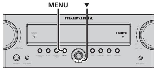
- Check that the power is on.
- While pressing the unit's MENU button, hold down the cursor button for at least 3 seconds.
After "M-CLEAR" has appeared on the display, the STANDBY mode is established, the settings that were selected are initialized, and the default settings are restored.
OTHERS
SURROUND MODE
This unit is equipped with many surround modes. These are provided to reproduce a variety of surround sound effects, according to the content of the source to be played.
The available surround modes may be restricted depending on the input signal and speaker setup.
The relationship between the selected surround mode and the input signal
The surround mode is selected with the surround mode selector on the unit or the remote controller. However, the sound you hear is subject to the relationship between the selected surround mode and the input signal. That relationship is as follows:
| Surround Mode | Input Signal | Decoding | Output Channel | Front information display | ||||
| L/R | C | SL/SR | SBL/SBR | SubW | Signal format indicators | |||
| AUTO | Dolby Surr.EX | Dolby Digital EX | O | O | O | O | O | ☐ D, EX |
| Dolby D (5.1ch) | Dolby Digital 5.1 | O | O | O | - | O | ☐ D | |
| Dolby D (2ch) | Dolby Digital 2.0 | O | - | - | - | O | ☐ D | |
| Dolby D (2ch Surr) | Pro Logic IIx movie | O | O | O | O | O | ☐ D | |
| Dolby Digital Plus (2ch) | DolbyDigital + | O | - | - | - | O | ☐ D, + | |
| Dolby Digital Plus (5.1ch) | DolbyDigital + | O | O | O | - | O | ☐ D, + | |
| Dolby Digital Plus (6.1ch) | DolbyDigital + | O | O | O | O | O | ☐ D, + | |
| Dolby Digital Plus (7.1ch) | DolbyDigital + | O | O | O | O | O | ☐ D, + | |
| Dolby TrueHD (2ch) | DolbyTrueHD | O | - | - | - | O | ☐ HD | |
| Dolby TrueHD (5.1ch) | DolbyTrueHD | O | O | O | - | O | ☐ HD | |
| Dolby TrueHD (6.1ch) | DolbyTrueHD | O | O | O | O | O | ☐ HD | |
| Dolby TrueHD (7.1ch) | DolbyTrueHD | O | O | O | O | O | ☐ HD | |
| DTS-ES | DTS-ES | O | O | O | O | O | DTS, ES | |
| DTS 96/24 | DTS-96/24 | O | O | O | - | O | DTS, 96/24 | |
| DTS (5.1ch) | DTS 5.1 | O | O | O | - | O | DTS | |
| DTS-HD (2ch) | DTS-HD | O | - | - | - | O | DTS, HD | |
| DTS-HD (5.1ch) | DTS-HD | O | O | O | - | O | DTS, HD | |
| DTS-HD (6.1ch) | DTS-HD | O | O | O | O | O | DTS, HD | |
| DTS-HD (7.1ch) | DTS-HD | O | O | O | O | O | DTS, HD | |
| Multi Ch-PCM | Multi Ch-PCM | O | O | O | O | O | ||
| Multi Ch-PCM 96kHz | Multi Ch-PCM 96kHz | O | O | O | O | O | ||
| PCM (Audio) | PCM (Stereo) | O | - | - | - | O | ||
| PCM 96kHz | PCM (Stereo 96kHz) | O | - | - | - | O | ||
| Analog | Stereo | O | - | - | - | O | ||
| SOURCE DIRECT | Dolby Surr.EX | Dolby Digital EX | O | O | O | O | O | ☐ D, EX |
| Dolby D (5.1ch) | Dolby Digital 5.1 | O | O | O | - | O | ☐ D | |
| Dolby D (2ch) | Dolby Digital 2.0 | O | - | - | - | O | ☐ D | |
| Surround Mode | Input Signal | Decoding | Output Channel | Front information display | ||||
| L/R | C | SL/SR | SBL/SBR | SubW | Signal format indicators | |||
| DOLBY (PLIIx movie) (PLIIx music) (PLIIx game) | Dolby Digital Plus (2ch) | Pro Logic IIx | O | O | O | O | O | ☐ D, + |
| Dolby Digital Plus (5.1ch) | DolbyDigital + | O | O | O | - | O | ☐ D, + | |
| Dolby TrueHD (2ch) | Pro Logic IIx | O | O | O | O | O | ☐ HD | |
| Dolby TrueHD (5.1ch) | DolbyTrueHD | O | O | O | - | O | ☐ HD | |
| Multi Ch-PCM | Multi Ch-PCM + PLIIx | O | O | O | O | O | ☐ PLIIx | |
| PCM (Audio) | Pro Logic IIx | O | O | O | O | O | ☐ PLIIx | |
| Analog | Pro Logic IIx | O | O | O | O | O | ☐ PLIIx | |
| DTS (Neo:6 Cinema) (Neo:6 Music) | DTS-ES | DTS 5.1 | O | O | O | - | O | DTS, ES |
| DTS 96/24 | DTS-96/24 | O | O | O | - | O | DTS, 96/24 | |
| DTS (5.1ch) | DTS 5.1 | O | O | O | - | O | DTS | |
| DTS-HD (2ch) | Neo:6 | O | O | O | O | O | DTS, HD | |
| DTS-HD (5.1ch) | DTS-HD | O | O | O | - | O | DTS, HD | |
| DTS-HD (6.1ch) | DTS-HD | O | O | O | O | O | DTS, HD | |
| DTS-HD (7.1ch) | DTS-HD | O | O | O | O | O | DTS, HD | |
| PCM (Audio) | Neo:6 | O | O | O | O | O | NEO:6 | |
| Analog | Neo:6 | O | O | O | O | O | NEO:6 | |
| STEREO | Dolby Surr:EX | Stereo | O | - | - | - | O | ☐ D, EX |
| Dolby D (5.1ch) | Stereo | O | - | - | - | O | ☐ D | |
| Dolby D (2ch) | Stereo | O | - | - | - | O | ☐ D | |
| Dolby D (2ch Surr) | Stereo | O | - | - | - | O | ☐ D | |
| Dolby Digital Plus (2ch) | Stereo | O | - | - | - | O | ☐ D, + | |
| Dolby Digital Plus (5.1ch) | Stereo | O | - | - | - | O | ☐ D, + | |
| Dolby Digital Plus (6.1ch) | Stereo | O | - | - | - | O | ☐ D, + | |
| Dolby Digital Plus (7.1ch) | Stereo | O | - | - | - | O | ☐ D, + | |
| Dolby TrueHD (2ch) | Stereo | O | - | - | - | O | ☐ HD | |
| Dolby TrueHD (5.1ch) | Stereo | O | - | - | - | O | ☐ HD | |
| Dolby TrueHD (6.1ch) | Stereo | O | - | - | - | O | ☐ HD | |
| Dolby TrueHD (7.1ch) | Stereo | O | - | - | - | O | ☐ HD | |
| DTS-ES | Stereo | O | - | - | - | O | DTS, ES | |
| DTS 96/24 | Stereo | O | - | - | - | O | DTS, 96/24 | |
| DTS (5.1ch) | Stereo | O | - | - | - | O | DTS | |
| DTS-HD (2ch) | Stereo | O | - | - | - | O | DTS, HD | |
| DTS-HD (5.1ch) | Stereo | O | - | - | - | O | DTS, HD | |
| DTS-HD (6.1ch) | Stereo | O | - | - | - | O | DTS, HD | |
| DTS-HD (7.1ch) | Stereo | O | - | - | - | O | DTS, HD | |
| Multi Ch-PCM | Stereo | O | - | - | - | O | ||
| Multi Ch-PCM 96kHz | Stereo | O | - | - | - | O | ||
| PCM (Audio) | Stereo | O | - | - | - | O | ||
| PCM 96kHz | Stereo | O | - | - | - | O | ||
| Analog | Stereo | O | - | - | - | O | ||
| MULTI CH STEREO | PCM (Audio) | Multi channel stereo | O | O | O | O | O | |
| PCM 96kHz | Multi channel stereo | O | O | O | O | O | ||
| Analog | Multi channel stereo | O | O | O | O | O | ||
| VIRTUAL | PCM (Audio) | Virtual | O | O | O | O | O | |
| PCM 96kHz | Virtual | O | O | O | O | O | ||
| Analog | Virtual | O | O | O | O | O | ||
Notes
- Dolby Digital (2 channel L / R ): Speakers for signal with Dolby Surround are fully equipped.
- No sound is outputs from the surround speaker, center speaker and subwoofer if the DVD disc has no surround data.
- Surround modes other than Stereo are not available during Dolby TrueHD, Dolby Digital Plus, or DTS-HD playback.
If surround modes other than Stereo are selected and Dolby TrueHD, Dolby Digital Plus, or DTS-HD content is played, the surround mode setting is disabled.
Abbreviations
L/R : Front speakers
C:Center speaker
SL/SR : Surround speakers
BR : Surround back speakers
SubW: Subwoofer
AUTO
When this mode is selected, the unit determines whether the digital input signal is Dolby Digital, Dolby Digital Surround EX, Dolby Digital Plus, Dolby TrueHD, DTS-HD, DTS, DTS-ES, DTS 96/24 or PCM audio.
Surround EX & DTS-ES will operate for multichannel sources that have a Dolby Digital Surround EX or DTS-ES auto trigger flag in the digital signal.
When a Dolby Digital or DTS signal is input, the number of channels for which the corresponding signal is encoded will be played.
Inputting a Dolby Digital two channel signal with Dolby surround status automatically subjects that signal to Pro Logic IIx movie processing before play.
PCM 96 kHz source material can be played in this mode.
Notes
- When you use this mode with certain DVD and CD players, performing operations such as skip or stop may momentarily interrupt the output.
- When the signal is not decoded, the mode is changed to AUTO mode automatically. See page 38 to confirm the available decoding modes.
SOURCE DIRECT
In SOURCE DIRECT mode, the tone control circuit ROOM EQ and HT-EQ are bypassed for full-range frequency response and the purest audio reproduction.
Dolby Digital EX
In a movie theater, film soundtracks that have been encoded with Dolby Digital Surround EX technology are able to reproduce an extra channel which has been added during the mixing of the program.
This channel, called surround back, places sounds behind the listener in addition to the currently available front left, front center, front right, surround right, surround left and subwoofer channels.
This additional channel provides the opportunity for more detailed imaging behind the listener and brings more depth, spacious ambience and sound localization than ever before.
Dolby Digital EX is not available in systems that do not have without surround back speaker(s).
DTS-ES (Discrete 6.1, Matrix 6.1)
DTS-ES adds the surround center channel audio to the DTS 5.1 channel format to improve the acoustic positioning, and makes acoustic image movement more natural with the 6.1 channel reproduction.
This unit incorporates a DTS-ES-decoder, which can handle DTS-ES Discrete-encoded and DTS-ES Matrix-encoded program sources from DVD, etc.
DTS-ES Discrete 6.1 features digital discrete recording of all channels, including the surround back channel(s), and higher quality audio reproduction.
DTS-ES is not available in systems that do not have surround back speakers.
MODE
(Dolby Digital, Pro Logic IIx MOVIE, Pro Logic IIx MUSIC, Pro Logic IIx GAME)
This mode is used with source materials encoded in Dolby Digital and Dolby Surround.
DOLBY DIGITAL
This mode is enabled when playing source materials encoded in Dolby Digital.
Playing multichannel-encoded 5.1 channel Dolby Digital sources provides 5 main audio channels (left, center, right, surround left and surround right) and a Low Frequency Effect channel.
Dolby Digital EX decoding is not available in this mode.
Dolby Pro Logic IIx has 5 modes:
Pro Logic IIx MOVIE
This mode provides 6.1 or 7.1 channel surround sound from Dolby Surround, encoded stereo movie soundtracks.
Pro Logic IIx MUSIC
This mode provides 6.1 or 7.1 channel surround sound from conventional stereo sources (analog or digital), such as CD, tape, FM, TV, stereo VCR, etc.
Pro Logic IIx GAME
This mode restores the impact low-frequency surround effects by routing them to the system's subwoofer.
5.1ch + Pro Logic IIx Movie
This mode provides 7.1 channel surround sound from 5.1 channel sources movie soundtracks.
5.1ch + Pro Logic IIx Music
This mode provides 6.1 or 7.1 channel surround sound from 5.1 channel sources music soundtracks.
Notes
- Pro Logic IIx mode will decode as Pro Logic II mode when the Surr. B is set to "NO" from SPEAKER SETUP menu. (See page 22)
- Pro Logic IIx mode is available for a 2 channel input signal which is encoded in Dolby Digital, HDCD or PCM format.
DTS
dts, Neo:6 Cinema, Neo:6 Music
This mode is for DTS-encoded source materials such as laserdisc, CD and DVD. Neo:6 is for some 2 channel sources.
dt
This mode is enabled when playing source materials encoded in dts multichannel.
Playing multichannel encoded-5.1 channel dts sources provides five main audio channels (left, center, right, surround left and surround right) and a Low Frequency Effects channel.
dts-ES decoding is not available in this mode.
The DTS mode cannot be used when an analog input has been selected.
Neo:6 Cinema, Neo:6 Music
This mode decodes 2 channel signals into 6 channel signals using high-accuracy digital matrix technology.
The DTS Neo:6 decoder has near-discrete properties in the frequency characteristics of the channels as well as in channel separation.
According to the signals to be played back, DTS Neo:6 uses either the Neo:6 Cinema mode optimized for movie playback or the Neo:6 Music mode optimized for music playback.
Note
- The Neo:6 mode is available for 2 channel input signals which are encoded in Dolby Digital, HDCD or PCM format.
STEREO
This mode bypasses all surround processing.
In stereo program sources, the left and right channels play normally when PCM audio or analog stereo is input.
With Dolby Digital and DTS sources, the 5.1 channels are converted to two channel stereo. 96 kHz PCM source material can be played back in stereo mode.
OTHERS
MULTI CH STEREO
This mode is used to create a wider, deeper and more natural soundstage from two channel source material. This is done by feeding the left channel signal to both the left front and left surround speakers and the right channel signal to both the right front and right surround speakers. Additionally, the center channel reproduces a mix of the right and left channels.
Note
- Audio is not output from the CENTER channel when using MULTI CH. MUSIC mode.
VIRTUAL
This mode provides a dynamic and broad sound space to heighten the overall impact of the sound track.
CAUTION
Note for DTS
- To connected DVD player, laserdisc player or CD player needs to support DTS digital output. You may not be able to play some DTS source signals from certain CD players and LD players even if you connect the player to the unit digitally. This is because the digital signal has been processed (such as the output level, sampling frequency or frequency response), and the unit cannot recognize the signal as DTS data.
- Depending on the player used, DTS play may produce a short noise. This is not a malfunction.
- While signals from a DTS laserdisc or CD are playing in another surround mode, you cannot switch to digital input or from digital input to analog input from the INPUT SETUP in the MAIN MENU or by pressing the A/D button.
- The outputs for VCR OUT output analog audio signals only. Do not record from CDs or LDs that support DTS using these outputs. If you do, the DTS-encoded signal will be recorded as noise.
Note or Dolby Digital Surround EX
- When playing Dolby Digital Surround EX-encoded software in 6.1 channels, it is required to set the EX/ES mode.
Note that some Dolby Digital Surround EX-encoded software does not contain the identification signal. In this case, set the EX/ES mode manually.
Note for 96 kHz PCM audio
- The AUTO, Pure Direct, and Stereo modes can be used when playing PCM signals with a sampling frequency of 96kHz (such as from DVD-Video/ Audio discs).
Certain DVD player models inhibit digital output. For details, refer to the player's operation manual. - Some DVD discs feature copy protection. When using such disc, 96 kHz PCM signal are not output from the DVD player. For details, refer to the player's operation manual.
DESCRIPTION

dtts
Digital Surround ES | Neo:6 | 96/24
Manufactured under license under U.S. Patent #s: 5,451,942; 5,956,674; 5,974,380; 5,978,762; 6,226,616; 6,487,535; 7,003,467 & other U.S. and worldwide patents issued & pending. DTS, DTS Digital Surround, ES, and Neo:6 are registered trademarks and the DTS logos, Symbol and DTS 96/24 are trademarks of DTS, Inc. © 1996-2007 DTS, Inc. All Rights Reserved.
- dts Digital Surround
DTS was introduced in 1994 to provide 5.1 channels of discrete digital audio into home theater systems. DTSbringsyoupremiumqualitydiscretemultichannel digital sound to both movies and music.
DTS is a multichannel sound system designed to create full range digital sound reproduction.
The no compromise DTS digital process sets the standard of quality for cinema sound by delivering an exact copy of the studio master recordings to neighborhood and home theaters.
Now, every moviegoer can hear the sound exactly as the moviemaker intended.
DTS can be enjoyed in the home for either movies or music on of DVD's, LD's, and CD's.
- dts Neo:6
The advantages of discrete multichannel systems over matrix are well known.
But even in homes equipped for discrete multichannel, there remains a need for high-quality matrix decoding. This is because of the large library of matrix surround motion pictures available on disc and on VHS tape; and analog television broadcasts. The typical matrix decoder of today derives a center channel and a mono surround channel from two-channel matrix stereo material. It is better than a simple matrix in that it includes steering logic to improve separation, but because of its mono, band-limited surround it can be disappointing to users accustomed to discrete multichannel.
Neo:6 offers several important improvements as follow,
- Neo:6 provides up to six full-band channels of matrix decoding from stereo matrix material. Users with 6.1 and 5.1 systems will derive six and five separate channels, respectively, corresponding to the standard home-theater speaker layouts.
- Neo:6 technology allows various sound elements within a channel or channels to be steered separately, and in a way which follows naturally from the original presentation.
- Neo:6 offers a music mode to expand stereo nonmatrix recordings into the five- or six-channel layout, in a way which does not diminish the subtlety and integrity of the original stereo recording.
- dts Digital Surround ES®
DTS-ES Extended Surround is a new multichannel digital signal format developed by Digital Theater Systems Inc. While offering high compatibility with the conventional DTS Digital Surround format, DTS-ES Extended Surround greatly improves the 360-degree surround impression and space expression thanks to further expanded surround signals. This format has been used professionally in movie theaters since 1999.
In addition to the 5.1 surround channels (FL, FR, C, SL, SR and LFE), DTS-ES Extended Surround also offers the SB (Surround Back) channel for surround playback with a total of 6.1 channels. DTS-ES Extended Surround includes two signal formats with different surround signal recording methods, as DTS-ES Discrete 6.1 and DTS-ES Matrix 6.1.
- dts Digital Surround 96/24
The stereo CD is a 16-bit medium with sampling at 44.1kHz . Professional audio has been 20- or 24-bit for some time, and there is increasing interest in higher sampling rates both for recording and for delivery into the home. Greater bit depths provide extended dynamic range. Higher sampling rates allow wider frequency response and the use of antilalias and reconstruction filters with more favorable aural characteristics.
DTS 96/24 allows for 5.1channel sound tracks to be encoded at a rate of 96kHz / 24 bits on DVD-Video titles.
When DVD-video appeared, it became possible to deliver 24-bit, 96kHz audio into the home, but only in two channels, and with serious limitations on picture. This capability has had little use.
DVD-audio allows 96/24 in six channels, but a new player is needed, and only analog outputs are provided, necessitating the use of the D/A converters and analog electronics provided in the player.
DTS 96/24 offers the following:
- Sound quality transparent to the original 96/24 master.
- Full backward compatibility with all existing decoders. (Existing decoders will output a 48 kHz signal)
- No new player required: DTS 96/24 can be carried on DVD-video, or in the video zone of DVD-audio, accessible to all DVD players.
4.96/24 5.1-channel sound with full-quality full-motion video, for music programs and motion picture soundtracks on DVD-video.

dtshD
Master Audio
DTS-HD Master Audio is capable of delivering audio that is a bit-for-bit identical to the studio master. DTS-HD Master Audio delivers audio at super high variable bit rates -24.5 mega-bits per second (Mbps) on Blu-ray discs and 18.0 Mbps on HD-DVD - that are significantly higher than standard DVDs. This bit stream is so "fast" and the transfer rate is so "high" that it can deliver the Holy Grail of audio: 7.1 audio channels at 96k sampling frequency/24 bit depths that are identical to the original. With DTS-HD Master Audio, you will be able to experience movies and music, exactly as the artist intended: clear, pure, and uncompromised.
Manufactured under license under U.S. Patent #s: 5,451,942; 5,956,674; 5,974,380; 5,978,762; 6,226,616; 6,487,535 & other U.S. and worldwide patents issued & pending.
DTS is a registered trademark and the DTS logos, Symbol, DTS-HD and DTS-HD Master Audio are trademarks of DTS, Inc. © 1996-2007 DTS, Inc. All Rights Reserved.

dtshD
High Resolution Audio
DTS-HD High Resolution Audio can deliver up to 7.1 channels of sound that is virtually indistinguishable from the original. DTS-HD High Resolution Audio delivers audio at high constant bit rates superior to standard DVDs—6.0 Mbps on Blu-ray discs and 3.0 Mbps on HD-DVD to produce outstanding sound quality. It is capable of delivering up to 7.1 channels at 96k sampling frequency/24 bit depth resolution. It allows content creators to deliver rich, high definition audio on movies where disc space may not allow for DTS-HD Master Audio.
Manufactured under license under U.S. Patent #s: 5,451,942; 5,956,674; 5,974,380; 5,978,762; 6,226,616; 6,487,535 & other U.S. and worldwide patents issued & pending. DTS is a registered trademark and the DTS logos, Symbol, DTS-HD, DTS-HD High Resolution
Audio and DTS-HD High Res Audio are trademarks of DTS, Inc. © 1996-2007 DTS, Inc. All Rights Reserved.

DOLBY
DIGITAL EX RO LOGIC IIx
Dolby Digital identifies the use of Dolby Digital audio coding for such consumer formats as DVD and DTV. As with film sound, Dolby Digital can provide up to five full-range channels for left, center, and right screen channels, independent left and right surround channels, and a sixth (.1") channel for low-frequency effects.
Dolby Surround Pro Logic II is an improved matrix decoding technology that provides better spatiality and directionality on Dolby Surround program material; provides a convincing three-dimensional soundfield on conventional stereo music recordings; and is ideally suited to bring the surround experience to automotive sound. While conventional surround programming is fully compatible with Dolby Surround Pro Logic II decoders, soundtracks will be able to be encoded specifically to take full advantage of Pro Logic II playback, including separate left and right surround channels. (Such material is also compatible with conventional Pro Logic decoders.)
Dolby Digital EX creates six full-bandwidth output channels from 5.1-channel sources. This is done using a matrix decoder that derives three surround channels from the two in the original recording. For best results, Dolby Digital EX should be used with movies soundtracks recorded with Dolby Digital Surround EX.
About Dolby Pro Logic IIx
Dolby Pro Logic IIx technology delivers a natural and immersing 7.1-channel listening experience to the home theater environment. A product of Dolby's expertise in surround sound and matrix decoding technologies, Dolby Pro Logic IIx is a complete surround sound solution that maximizes the entertainment experience from stereo as well as 5.1-channel encoded sources.
Dolby Pro Logic IIx is fully compatible with Dolby Surround Pro Logic technology and can optimally decode the thousands of commercially available Dolby Surround encoded video cassettes and television programs with enhanced depth and spatiality. It can also process any high-quality stereo or Advanced Resolution 5.1-channel music content into a seamless 6.1- or 7.1-channel listening experience.

DOLBY
TRUEID
Dolby® TrueHD is Dolby's next-generation lossless technology developed for high-definition disc-based media. Dolby TrueHD delivers tantalizing sound that is bit-for-bit identical to the studio master, unlocking the true high-definition entertainment experience on next-generation discs. When coupled with high-definition video, Dolby TrueHD offers an unprecedented home theater experience that lets you enjoy sound as stunning as the high-definition picture.

DOLBY
DIGITAL PLUS
Dolby Digital Plus is a highly sophisticated and versatile audio codec based on Dolby Digital and designed specifically to adapt to the changing demands of future audio, video delivery, and audio storage systems while simultaneously retaining backwards compatibility with the existing Dolby Digital 5.1-channel home theater systems in use today.
Manufactured under license from Dolby Laboratories. "Dolby", "Pro Logic", "Surround EX", and the double-D symbol are trademarks of Dolby Laboratories.
HOMI
HDMI, the HDMI and High-Definition Multimedia Interface are trademarks or registered trademarks of HDMI Licensing LLC.
OTHERS
SPECIFICATIONS

FM TUNER SECTION
Frequency Range.87.5 MHz to 108.0 MHz
Usable Sensitivity.IHF 1.8 V / 16.4 dBf
Signal to Noise Ratio (Mono/Stereo) 75 dB / 70 dB
Distortion (Mono/Stereo) 0.3% / 0.5%
Stereo Separation. 1 kHz 35 dB
Alternate Channel Selectivity ...± 300 kHz 60 dB
Image Rejection 98 MHz 60 dB
Tuner Output Level (1 kHz, ± 40 kHz Dev)

AM TUNER SECTION
Frequency Range. 531 kHz to 1602 kHz
Signal to Noise Ratio. 40 dB
Usable Sensitivity (Loop Antenna)....400 V / m
Distortion. 400Hz,30% Mod. 0.7%
Selectivity. ± 18kHz70 dB

AUDIO SECTION
Power Output (20 Hz - 20 kHz/THD=0.08%)
Front L&R (8 ohm load, Per channel) ..50 W
Center (8 ohm load, Per channel) ......... 50 W
Surround L&R (8 ohm load, Per channel) 50 W
Surround Back L&R
(8 ohm load, Per channel) 50 W
Power Output
Front L&R (6 ohm load, Per channel) .... 60 W
Center (6 ohm load, Per channel) 60 W
Surround L&R (6 ohm load, Per channel) 60 W
Surround Back L&R
(6 ohm load, Per channel) 60 W
Input Sensitivity/Impedance .... 200 mV / 47 kΩ
Signal to Noise Ratio(Analog Input / Pure Direct) 100 dB
Frequency Response
(Analog Input / Pure Direct)
8 Hz to 100 kHz (±3 dB)
(Digital Input / 96 kHz PCM)
8 Hz to 45 kHz (±3 dB)
VIDEO
Television Format NTSC/PAL
Input Level/Impedance. 1 Vp-p / 75 Ω
Output Level/Impedance. 1 Vp-p / 75 Ω
Video Frequency Response
5 Hz to 8 MHz (-1 dB)
Video Frequency (Component)
5 Hz to 80 MHz (-1 dB)
S/N 60 dB
HDMI
Version 1.3a [INPUT]
1.3a [OUTPUT]
GENERAL
Power Requirement......AC 230 V 50 / 60 Hz
Power Consumption 250 W
Standby Power Consumption. 0.5 W
Specifications subject to change without prior notice.
USING HEADPHONES
Take care not to turn up the volume too high while you are using headphones. Listening to sound at high-volume levels for prolonged periods can negatively affect your hearing.
COPYRIGHT
Recording and playback of any material may require consent. For further information refer to the following:
Copyright Act 1956
Dramatic and Musical Performers Act 1958
— Performers Protection Acts 1963 and 1972
— Any subsequent statutory enactments and orders
CLEANING OF EQUIPMENT EXTERNAL SURFACES
The exterior finish of your unit will last indefinitely with proper care and cleaning, Never use scouring pads, steel wool, scourging powders or harsh chemical agents (e.g., lye solution), alcohol, thinner, benzine, insecticide or other volatile substances as these wil mar the finish of the equipment. Likewise, never use cloths containing chemical substances. If the equipment get dirty, wipe the external surfaces with a soft, lint-free cloth.
If the equipment becomes heavily soiled:
- dilute some washing up liquid in water, in a ratio of one part detergent to six parts water.
- dip a soft, lint free in the solution and wring the it is damp.
- wipe the equipment with the damp cloth.
- dry the equipment by wiping it with a dry cloth.

REPAIRS
Only the most competent and qualified service technicians should be allowed to service the factory-trained warranty station personnel have the knowledge and special facilities needed for repair and calibration of this precision equipment. After the warranty period has expired, repairs will be performed for a charge if the equipment can be returned to normal operation.
In the event of difficulty, refer to your dealer or write directly to the nearest location to you that is listed on the Marantz Authorized Service Station list. If writing, please include the model and serial number of the equipment together with a full description of what you think is abnormal about the equipment's behavior.
SETUP CODES
TV
Acer. 1141
Admiral. 1002, 1009, 1089
Aiko. 1059
Aiwa 1117, 1118
Akai. 1001
Amtron 1023
Anam 1113
Anam National. 1023, 1069, 1092
AOC. 1003, 1024, 1049, 1127
Audiovox. 1023
Bell & Howell 1009, 1025
Bengq. 1104, 1142
Broksonic 1003, 1097, 1098, 1113
Celebrity. 1001
Citizen. 1003, 1013, 1023
1026, 1059, 1063
Colortyme 1003, 1043
Contec. 1113
Contec/Cony. 1023, 1045, 1047
Craig. 1020, 1022, 1023, 1113
Crown 1023, 1067
Curtis Mathes 1003, 1013, 1025
1026, 1062, 1103, 1110
Daewoo. 1003, 1013, 1024, 1035
1036, 1059, 1084, 1101
Daytron 1003, 1013, 1016
Dimensia. 1103, 1110
Dumont. 1003, 1010, 1153
Electroband. 1001
Electrohome. 1001, 1003, 1069, 1133
Emerson. 1003, 1013, 1015
1020, 1021, 1022, 1023
1025, 1038, 1044, 1045
1048, 1055, 1061, 1094
1096, 1099, 1101, 1113
Envision. 1003
Fisher. 1025, 1051, 1091, 1160
Fujitsu 1038, 1124, 1125, 1155
Funai 1023, 1038, 1113
Gateway 1150
GE. 1003, 1018, 1022, 1046
1054, 1069, 1085, 1103
1110, 1113, 1133, 1136, 1153
Goldstar 1003, 1013, 1024
1030, 1045, 1080
1100, 1112, 1154
Hallmark. 1003
Hisense 1116
Hitachi 1003, 1012, 1031, 1032
1037, 1041, 1045, 1047
1065, 1068, 1082, 1088
1094, 1139, 1140, 1145, 1159
Infinity 1067
Janeil 1134
JBL. 1067
JC Penney 1003, 1013, 1018
1019, 1024, 1026
1046.1047.1054
1063, 1083, 1085
1100, 1103, 1110
1112, 1133, 1154
Jensen 1003
JVC 1028, 1029, 1045
1047, 1050, 1060, 1065
Kawasho 1001, 1003
Kenwood. 1003
Kloss Novabeam 1023, 1056, 1057, 1134
KTV 1013, 1023, 1033
1034, 1073, 1099, 1113
LG. 1024, 1030
M.Wards. 1002, 1009, 1038
Magnavox. 1003, 1052, 1053
1056, 1057, 1063
1067, 1081, 1106
Marantz. 1003, 1031, 1067, 1122
Mitsubishi 1003, 1024, 1051
1115, 1122, 1133
Motorola. 1014, 1069
NEC. 1003, 1012, 1024, 1043, 1069
NET-TV 1137, 1150
Orion. 1020, 1096
Panasonic. 1017, 1067, 1069, 1095, 1111
Philips. 1003, 1011, 1045, 1052
1054, 1056, 1057, 1058
1063, 1067, 1069, 1106
Pioneer. 1003, 1018, 1037
1070, 1071, 1094
1145, 1147, 1149
Plasmsync 1135
Portland 1003, 1013, 1024, 1059
Price Club 1026
Prism 1018
Proscan. 1004, 1005, 1006, 1007
1008, 1085, 1103, 1110
Proton. 1003, 1045
Quasar. 1010, 1069, 1073, 1111, 1153
Radio Shack. 1003, 1013, 1015
1023, 1024, 1025, 1045
1100, 1103, 1110, 1113
RCA. 1003, 1004, 1005
1006, 1007, 1008
1014, 1024, 1049, 1069
1075, 1079, 1085, 1087
1088, 1093, 1094, 1101
1103, 1110, 1113, 1153
Realistic 1025, 1103
Runco 1010, 1153
Sampo 1150
Samsung. 1003, 1013, 1024, 1026
1040, 1045, 1062, 1078
1083, 1090, 1100, 1105, 1114
1120, 1121, 1146, 1148, 1157
Sansui 1119
Sanyo 1003, 1025, 1051, 1072
1077, 1091, 1156, 1157, 1158
Sharp. 1003, 1013, 1014
1015, 1045, 1055, 1064
1066, 1076, 1089, 1123
Signature 1009
Sony. 1001, 1102, 1108
Soundesign 1003, 1023, 1038, 1063, 1113
Starlite 1023
Supre-Macy 1134
Sylvania 1003, 1039, 1042
1052, 1053, 1056, 1057
1063, 1067, 1089, 1151
Symphonic. 1023, 1039, 1044
Tandy 1014
Tatung 1069
Technics 1018
Techwood 1003, 1018
Teknika 1003, 1009, 1013, 1023
1024, 1026, 1038, 1045
1047, 1059, 1063, 1111, 1113
Telecaption. 1074
Toshiba. 1003, 1019, 1025
1026, 1042, 1074, 1098
1107, 1111, 1135, 1136
Totevision 1013
Universal. 1046, 1054
Video Concepts 1113
Viewsonic 1006, 1022, 1109
1128, 1129, 1130, 1131
1138, 1143, 1145, 1150
Wards. 1003, 1009, 1015
1024, 1038, 1044, 1046
1052, 1054, 1056, 1057
1067, 1086, 1103, 1110
White Westinghouse 1001, 1101
Yamaha 1003, 1024
Zenith 1003, 1009, 1010
1132, 1144, 1153
CD
AIWA. 3001, 3002, 3003
AKAI 3004, 3005, 3006
AUDIO 3007
AUDIO LABS 3008
CALIFORNIA 3008
CARVER. 3009, 3010, 3011
CASIO 3012,3020
CURTIS 3012,3020
DENON 3013
EMERSON 3014
FISHER 3011, 3015, 3016, 3017, 3018
GE. 3019
GENEXXA 3014,3020,3021
HARMON 3022,3023,3051
HITACHI 3020
INKEL 3024
JC PENNEY 3012, 3020, 3025
JVC 3026,3027
KARDON 3022, 3023, 3051
KENWOOD 3028,3029,3030,3031
3032, 3033
KRELL 3010
LUXMAN 3035, 3036, 3037, 3038
LX I. 3012, 3014, 3020
MAGNAVOX 3010,3039,3040
MARANTZ 3010,3041,3042,3043
MATHES 3012,3020
MCS. 3012, 3020
MGA 3023
MISSION 3010
SONY 3039,3079,3080,3081,3082,3097
3098, 3099, 3100, 3101
SYLVANIA 3010
SYMPHONIC 3083
TEAC. 3016, 3042, 3057, 3083, 3084
3085, 3086
TECHNICA 3007,3008,3061,3087,3088
THETA DIGITAL 3040
TOSHIBA. 3045
VICTOR. 3026
YAMAHA. 3007, 3089, 3090, 3091, 3092
ZENITH. 3016, 3093, 3094, 3095, 3096
DVD
Aiwa 2036, 2037
Apex 2012, 2017, 2018, 2019, 2021, 2034
BOSE 2038,2039,2063
Denon 2047, 2048
Funai. 2049
GE. 2009, 2020, 2029, 2033
Harman Kardon 2061
Hitachi 2008, 2012, 2031
JVC 2006, 2010, 2040
2041, 2042, 2043
Kenwood 2053, 2054
Koss. 2058
Magnavox. 2007, 2011, 2023, 2025
Marantz. 2025, 2065
Mitsubishi 2011, 2015
Onkyo 2062
Oritron 2009, 2030
Panasonic. 2003, 2015, 2016, 2055
Philips. 2007, 2011, 2058
Pioneer. 2002, 2014, 2056
Proscan. 2009, 2020, 2032
RCA. 2005, 2009, 2020, 2035, 2057
Sampo 2041
Samsung 2008, 2012, 2022, 2024, 2027
Sanyo 2050, 2052
Sharp 2044, 2045
Sherwood 2051
Sony. 2001, 2013, 2059
Toshiba. 2004, 2008, 2026, 2028
Yamaha 2046, 2060
Zenith 2010
DSS
Alphastar 4027
Amstrad 4046,4047,4050
Atsky. 4048
B Sky B. 4021, 4045, 4046
Chaparral 4039
DIRECTV. 4001, 4016, 4044
DISH Network. 4030
Drake. 4026
Echostar....4007, 4017, 4018, 4019, 4020, 4062, 4063, 4064
Eurosky 4047, 4056
Express Vu. 4017
Foxtel 4051
Freesat. 4056
Fujitsu 4025
GE. 4002, 4008, 4009
General Instruments 4036, 4037
Gradient. 4044, 4057
Hitachi 4001, 4015
Hughes. 4001, 4016
Humax. 4049, 4050, 4051, 4052, 4053
Janeil. 4025
JVC 4001, 4017
Mitsubishi 4001, 4016
Nokia. 4058, 4059, 4060, 4061
Optima 4048
Panasonic. 4004, 4010
Philips. 4031, 4035, 4044, 4057
Proscan. 4002, 4008, 4009, 4011
Radio Shack. 4036, 4037
RCA. 4002, 4008, 4009, 4029
Realistic 4040
Rural Cable. 4036
Samsung. 4022, 4027, 4042, 4043, 4050, 4054, 4055
Schneider. 4041, 4043
SKY 4044,4045,4057
Skyplus. 4048
Skysat. 4041, 4047, 4056
Sony. 4003, 4012, 4014, 4065, 4066, 4067
Star Choice. 4032
StarTrak 4024
STS 4038
SuperDish 4028
Teac 4049
Thomson 4046, 4056
Toshiba. 4001, 4034
Uniden. 4005, 4006, 4013
Universum 4056
Video Pall. 4025
Zenith 4023, 4025, 4033
BD (Blu-ray)
Denon. 5034, 5035, 5036
Hitachi. 5031, 5032, 5033
Integra. 5013
JVC. 5014, 5015, 5017, 5018, 5019, 5020
LG. 5010, 5011
Marantz. 5026, 5027
Mitsubishi 5024, 5025
Onkyo 5013
Panasonic. 5001, 5002, 5003
Philips. 5004
Pioneer. 5005
RCA. 5012
Samsung 5005
Sharp. 5028, 5029, 5030
Sony. 5007, 5008, 5009, 5016
Toshiba 5012
Yamaha 5021, 5022, 5023
DIMENSIONS
Unit: mm (in)
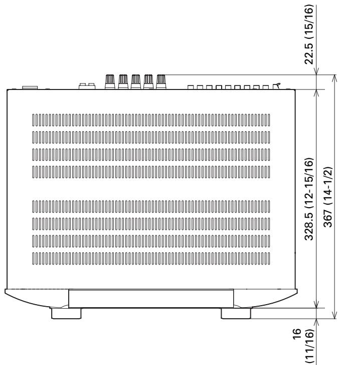
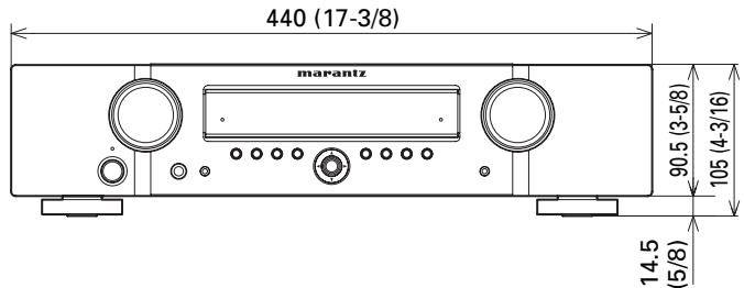
Weight: 8.6kg (19.0 lb)
Specifications subject to change without prior notice.
www.marantz.com
You can find your nearest authorized distributor or dealer on our website.
marantz
is a registered trademark.

- AV Surround Receiver
- NR1501
- ENGLISH
- WARRANTY
- RETAIN YOUR PURCHASE RECEIPT
- IMPORTANT
- FOR U.K. ONLY
- FRANÇAIS
- GARANTIE
- AVERTISSEMENTS
- ACCESSORIES CHECK
- CONTENTS
- FEATURES 2
- BEFORE USE 2
- NAMES AND FUNCTIONS. 4
- BASIC CONNECTIONS 8
- BASIC OPERATION 12
- AUTO SETUP SYSTEM
- 7-CHANNEL DISCRETE AMPLIFIER
- HDMI TERMINALS INCORPORATED
- VIDEO CONVERTER FEATURED
- WIDE-BAND COMPONENTVIDEO SELECTOR
- SLIM-LINE DESIGN FOR GREATER FREEDOM OF INSTALLATION
- OTHER FEATURES
- BEFORE USE
- EQUIPMENT MAINS WORKING SETTING
- DO NOT LOCATE IN THE FOLLOWING PLACES
- KEEP OBJECTS OFF
- CAUTIONS ON HANDLING BATTERIES
- OPERATIONAL RANGE
- Caution
- NAMES AND FUNCTIONS
- FRONT PANEL
- ① POWER switch and STANDBY indicator
- ② INPUT SELECTOR knob
- ③ SURROUND MODE button
- ④ AUTO button
- ⑤ SOURCE DIRECT button and indicator
- ⑥ MENU button
- ⑦ EXIT button
- ⑧ DISPLAY button
- ⑨ BAND button
- ⑩ MEMORY button
- ① HDMI indicator
- ⑫ VOLUME control knob
- AUX1 INPUT jack
- ⑭ Cursor (▲,▼,▲,▶) / ENTER button
- INFRARED receiving sensor window
- SETUP MIC jack
- PHONES jack
- FL DISPLAY AND INDICATOR
- Main Information Display
- AUTO indicator
- RDS indicators
- TUNER's indicators
- indicator
- MEM indicator
- PRESET indicator
- HDMI indicator
- indicator
- DIGITAL Indicator
- SIGNAL FORMAT indicators
- DTS
- DTS HD
- DTS ES
- DTS 96/24
- NEO:6
- HD
- D D
- D+
- DEX
- DO PLIIx
- DSP
- ANTENNA terminals
- FM (75Ω)
- AM
- 2VIDEO terminals (DVD,DSS,VCR)
- MONITOR OUT teminal
- COMPONENT VIDEO terminals (DVD, DSS, VCR)
- HDMI terminals (BLU-RAY, GAME, DVD, DSS)
- AC INLET
- SPEAKER SYSTEMS terminals
- DIGITAL AUDIO IN 1,2,3
- REMOTE CONTROL IN/OUT terminals
- SUB WOOFER PRE OUT terminal
- ANALOG AUDIO terminals (CD, DVD, DSS, VCR, AUX2)
- REMOTE CONTROLLER
- ON1/STANDBY 念 buttons
- (When AMP mode is selected)
- DIMMER button
- HT-EQ button
- SURR. MODE button
- S.DIRECT button
- EQ button
- A/D button
- MUTE button
- VOLUME + / - buttons
- AUDIO button
- INFO button
- , , , (CURSOR) / ENTER buttons
- (When Tuner mode mode is selected)
- PRESET + / PRESET - buttons
- TUNE /TUNE buttons
- EXIT / MEMO button
- (When TUNER mode is selected)
- CONTROL buttons
- LIP SYNC button
- CH SEL button
- T.MODE button
- T.DISP button
- PTY button
- BAND button
- BASS / CH +/- buttons
- (When DSS mode are selected)
- TREBLE +/- buttons
- REPEAT c3 button
- RANDOM xx button
- TV CONTROL buttons
- CLR button
- Numeric buttons
- T.TONE button
- MENU button
- TOP button
- DISPLAY button
- INPUT button
- INPUT button
- SETUP button
- SOURCE button
- Notes
- STEREO button
- AUTO button
- NIGHT button
- SLEEP button
- I / SOURCE ON/OFF button
- SET button
- SET indicator
- SEND indicator
- Infrared Transmitter
- BASIC CONNECTIONS
- SPEAKER PLACEMENT
- FRONT LEFT AND RIGHT SPEAKERS
- CENTER SPEAKER
- SUBWOOFER
- HEIGHT OF THE SPEAKER UNITS
- FRONT LEFT AND RIGHT SPEAKERS,
- AND A CENTER SPEAKER
- Note
- CONNECTING SPEAKERS
- CONNECTING SPEAKER WIRE
- FRONT R/L
- CENTER
- SURROUND R/L
- SURROUND BACK R/L
- CONNECTING AUDIO COMPONENTS
- CONNECTING DIGITAL AUDIO COMPONENTS
- CONNECTINGVIDEOCOMPONENTS
- VIDEO COMPONENT JACKS
- VIDEO JACK
- COMPONENT JACK
- CONNECTING HDMI COMPONENTS
- HDMI JACKS
- CONNECTING THE ANTENNAS
- CONNECTING THE SUPPLIED ANTENNAS
- CONNECTING AN OUTDOOR ANTENNAS
- CONNECTING OF AC POWER CABLE
- BASIC OPERATION
- AMP OPERATION
- TURNING ON THE UNIT
- SELECTING AN INPUT SOURCE
- ADJUSTING THE MAIN VOLUME
- ADJUSTING THE TONE (BASS & TREBLE) CONTROL
- (Using the remote controller)
- TEMPORARILY TURNING OFF THE SOUND
- TUNER OPERATION
- LISTENING TO THE TUNER
- AUTO TUNING
- (Using the unit)
- MANUAL TUNING
- SWITCHING THE FM MODE
- AMP MODE
- TUNER MODE
- ADVANCED CONNECTIONS
- SETUP
- ONSCREEN DISPLAY MENU SYSTEM
- SWITCHING BETWEEN PAL AND NTSC SIGNAL FORMATS
- SWITCHING THE ON SCREEN DISPLAY OUTPUT MODE
- RC006SR BUTTON CONTROL
- NR1501 FRONT BUTTON CONTROL
- SYSTEM SETUP
- 1-1 SUBWMODE
- Tip
- NORMAL
- - SW PLUS+
- 1-2 HDMI AUDIO OUT
- OFF
- ON
- 1-3 TONE CONTROL
- 1-4 HT-EQ
- 1-5VIDEOCONVERT
- - AUTO
- - COMPONENT
- CVBS
- INPUT SETUP
- 2-1 NAME
- 2-2 DIGITAL IN
- 2-3 AUDIO MODE
- HDMI
- DIGITAL
- ANALOG
- 2-4 AUTO SURROUND
- 2-5 LIP SYNC
- SPEAKER/R. EQ SETUP
- 3-1 AUTO SETUP
- HOW TO OPERATE AUTO SETUP
- 3-2 MANUAL SETUP
- SPEAKER CONFIG
- CENTER:
- SURROUND:
- SURR.B:
- 2CH:
- 1CH:
- NO:
- SUBWOOFER:
- SPEAKER DISTANCE
- FRONT LEFT:
- FRONT RIGHT:
- SURR RIGHT:
- SURR.B R:
- SURR.BL:
- SURR LEFT:
- SPEAKER X-OVER
- ROOM EQ CONFIG
- MODE
- ON:
- OFF:
- CH LEVEL SETUP
- 4-1 MEMORY MODE
- CALIBRATE:
- AUTO:
- REFFERENCE 1, REFFERENCE 2:
- 4-2 ADJUSTING THE CHANNEL LEVELS
- 4-3 LFE LEVEL SETUP
- 4-4 STORING THE CHANNEL LEVELS IN THE MEMORY
- SOUND PARAMETER
- 5-1 NIGHT MODE
- PANorama:
- CENTERWIDTH:
- DIMENSION:
- 5-3 NEO:6 PARAMETER
- ADVANCED OPERATION
- USING THE SLEEP TIMER
- DISPLAY MODE
- Input function:
- Volume:
- Input signals:
- DIMMER
- RECORDING AN ANALOG SOURCE
- To record the input source signal you are currently watching or listening to
- SELECTING ANALOG AUDIO INPUT OR DIGITAL AUDIO INPUT
- Auto mode:
- HDMI mode:
- Digital mode:
- Analog mode:
- NIGHT MODE
- ADJUSTING THE DIFFERENCE IN THE VOLUME LEVELS BETWEEN SPEAKERS (WITH TEST TONES)
- REGISTERING THE SPEAKER VOLUME LEVEL SETTING
- CALLING REGISTERED SPEAKER VOLUME LEVEL SETTINGS
- ADJUSTING DIFFERENCES IN VOLUME LEVELS BETWEEN SPEAKERS (WITHOUT TEST TONES)
- LISTENING THROUGH HEADPHONES
- HT-EQ
- ROOM EQ
- LIP.SYNC FUNCTION
- BILINGUAL FUNCTION
- MAIN:
- BIL MAIN
- SUB:
- BIL SUB
- MAIN + Sub:
- BIL M+S
- VIDEO CONVERT FUNCTION
- EXAMPLES OF CONNECTIONS
- TUNER OPERATIONS (PRESET MEMORY)
- AUTO PRESET MEMORY
- MANUAL PRESET MEMORY
- RADIO TEXT
- RDS DISPLAY
- PTY SEARCH
- Press the SOURCE button.
- PRESET MODE
- WHEN OPERATING NON-MARANTZ AV
- EQUIPMENTPRODUCTS
- Importants
- PROGRAMMING WITH THE 4-DIGIT CODE
- SCANNING THE CODE TABLE
- CHECKING THE CODE
- RESETTING THE CODE
- CONTROLLING MARANTZ COMPONENTS
- TROUBLESHOOTING
- WHEN MALFUNCTIONING HAS OCCURRED
- MEMORY BACKUP
- TO RESTORE THE DEFAULT SETTINGS (RESETTING)
- OTHERS
- SURROUND MODE
- The relationship between the selected surround mode and the input signal
- Abbreviations
- AUTO
- SOURCE DIRECT
- Dolby Digital EX
- DTS-ES (Discrete 6.1, Matrix 6.1)
- (Dolby Digital, Pro Logic IIx MOVIE, Pro Logic IIx MUSIC, Pro Logic IIx GAME)
- DOLBY DIGITAL
- Pro Logic IIx MOVIE
- Pro Logic IIx MUSIC
- Pro Logic IIx GAME
- 5.1ch + Pro Logic IIx Movie
- 5.1ch + Pro Logic IIx Music
- dts, Neo:6 Cinema, Neo:6 Music
- dt
- Neo:6 Cinema, Neo:6 Music
- STEREO
- MULTI CH STEREO
- VIRTUAL
- Note for DTS
- Note or Dolby Digital Surround EX
- Note for 96 kHz PCM audio
- DESCRIPTION
- dtts
- - dts Digital Surround
- - dts Neo:6
- - dts Digital Surround ES®
- - dts Digital Surround 96/24
- dtshD
- DOLBY
- DIGITAL EX RO LOGIC IIx
- About Dolby Pro Logic IIx
- TRUEID
- DIGITAL PLUS
- HOMI
- SPECIFICATIONS
- FM TUNER SECTION
- AM TUNER SECTION
- AUDIO SECTION
- VIDEO
- GENERAL
- USING HEADPHONES
- COPYRIGHT
- CLEANING OF EQUIPMENT EXTERNAL SURFACES
- REPAIRS
- SETUP CODES
- TV
- CD
- DVD
- DSS
- BD (Blu-ray)
- DIMENSIONS
- www.marantz.com
Brand : MARANTZ
Model : NR1501
Category : AV Receiver