
IS301E - Audio Dock MARANTZ - Free user manual and instructions
Find the device manual for free IS301E MARANTZ in PDF.


| Product type | Audio docking station |
| Brand | Marantz |
| Model | IS301E |
| Compatibility | iPod, iPhone, iPhone |
| Dimensions (approx.) | 300 x 150 x 100 mm |
| Weight (approx.) | 1.5 kg |
| Power supply | AC adapter 100-240 V, 50/60 Hz |
| Power consumption | 15 W (max) |
| Audio output | 3.5 mm headphone jack, built-in stereo speakers |
| Main functions | Charging connected device, audio playback, remote control |
| Maintenance and cleaning | Unplug before cleaning; use a dry cloth |
| Safety instructions | Do not expose to water, heat sources, do not block vents |
| Spare parts and repairability | Contact Marantz after-sales service |
| General information | Class B digital device complies with Canadian NMB-003 standard. Warranty: keep proof of purchase. |
Frequently Asked Questions - IS301E MARANTZ
User questions about IS301E MARANTZ
0 question about this device. Answer the ones you know or ask your own.
Ask a new question about this device
Download the instructions for your Audio Dock in PDF format for free! Find your manual IS301E - MARANTZ and take your electronic device back in hand. On this page are published all the documents necessary for the use of your device. IS301E by MARANTZ.
USER MANUAL IS301E MARANTZ
natural_image
Pure electrical circuit lines without any symbolsmarantz®
Wireless Dock for iPod IS301

Made for
iPod
CAUTION
RISK OF ELECTRIC SHOCK DO NOT OPEN

CAUTION: TO REDUCE THE RISK OF ELECTRIC SHOCK, DO NOT REMOVE COVER (OR BACK) NO USER-SERVICEABLE PARTS INSIDE REFER SERVICING TO QUALIFIED SERVICE PERSONNEL
The lightning flash with arrowhead symbol within an equilateral triangle is intended to alert the user to the presence of uninsulated “dangerous voltage” within the product’s enclosure that may be of sufficient magnitude to constitute a risk of electric shock to persons.

The exclamation point within an equilateral triangle is intended to alert the user to the presence of important operating and maintenance (servicing) instructions in the literature accompanying the product.
WARNING
TO REDUCE THE RISK OF FIRE OR ELECTRIC SHOCK, DO NOT EXPOSE THIS APPLIANCE TO RAIN OR MOISTURE.
NOTE:
This equipment has been tested and found to comply with the limits for a Class B digital device, pursuant to Part 15 of the FCC Rules. These limits are designed to provide reasonable protection against harmful interference in a residential installation. This equipment generates, uses and can radiate radio frequency energy and, if not installed and used in accordance with the instructions, may cause harmful interference to radio communications. However, there is no guarantee that interference will not occur in a particular installation. If this equipment does cause harmful interference to radio or television reception, which can be determined by turning the equipment off and on, the user is encouraged to try to correct the interference by one or more of the following measures:
Reorient or relocate the receiving antenna. Increase the separation between the equipment and receiver. Connect the equipment into an outlet on a circuit different from that to which the receiver is connected. Consult the dealer or an experienced radio/TV technician for help.
NOTE:
Changes or modifications may cause this unit to fail to comply with Part 15 of the FCC Rules and may void the user's authority to operate the equipment.
This Class B digital apparatus complies with Canadian ICES-003.
IMPORTANT SAFETY INSTRUCTIONS
READ BEFORE OPERATING EQUIPMENT
This product was designed and manufactured to meet strict quality and safety standards.
There are, however, some installation and operation precautions which you should be particularly aware of.
- Read these instructions.
- Keep these instructions.
- Heed all warnings.
-
Follow all instructions.
-
Do not use this apparatus near water.
-
Clean only with dry cloth.
-
Do not block any ventilation openings. Install in accordance with the manufacture's instructions.
-
Do not install near any heat sources such as radiators, heat registers, stoves, or other apparatus (including amplifiers) that produce heat.
-
Do not defeat the safety purpose of the polarized or grounding-type plug. A polarized plug has two blades with one wider than the other. A grounding type plug has two blades and a third grounding prong. The wide blade or the third prong are provided for your safety. If the provided plug does not fit into your outlet, consult an electrician for replacement of the obsolete outlet.
-
Protect the power cord from being walked on or pinched particularly at plugs, convenience receptacles, and the point where they exit from the apparatus.
-
Only use attachments/accessories specified by the manufacturer.
-
Use only with the cart, stand, tripod, bracket, or table specified by the manufacturer, or sold with the apparatus. When a cart is used, use caution when moving the cart/apparatus combination to avoid injury from tip-over.

-
Unplug this apparatus during lightning storms or when unused for long periods of time.
-
Refer all servicing to qualified service personnel. Servicing is required when the apparatus has been damaged in any way, such as power-supply cord or plug is damaged, liquid has been spilled or objects have fallen into the apparatus, the apparatus has been exposed to rain or moisture, does not operate normally, or has been dropped.
ENGLISH
WARRANTY
For warranty information, contact your local Marantz distributor.
RETAIN YOUR PURCHASE RECEIPT
Your purchase receipt is your permanent record of a valuable purchase. It should be kept in a safe place to be referred to as necessary for insurance purposes or when corresponding with Marantz.
IMPORTANT
When seeking warranty service, it is the responsibility of the consumer to establish proof and date of purchase. Your purchase receipt or invoice is adequate for such proof.
FOR U.K. ONLY
This undertaking is in addition to a consumer's statutory rights and does not affect those rights in any way.
FRANÇAIS
GARANTIE
- Do not expose the equipment to rain, moisture, dripping or splashing.
- Do not handle the AC adaptor with wet hands.
- Do not cover the ventilation with any items such as tablecloths, newspapers, curtains, etc.
- No naked flame sources, such as lighted candles, should be placed on the equipment.
- When disposing of used batteries, please comply with governmental regulations or environmental public instruction's rules that apply in your country or area.
- Make a space of about 0.1 meter around the unit.
- No objects filled with liquids, such as vases, shall be placed on the equipment.
- When the switch is in the OFF position, the equipment is not completely switched off from MAINS.
- The equipment shall be installed near the power supply so that the power supply is easily accessible.
- Do not expose the unit and batteries to excessive heat such as direct sunlight, fire or the like.
Français
AVERTISSEMENTS
In line with CE marking regulations: the CE mark and the class 2 identifier are added to the equipment:

| ENGLISH | A NOTE ABOUT RECYCLINGThis product's packaging materials are recyclable and can be reused. This product and the accessories packed together are the applicable product to the WEEE directive except batteries.Please dispose of any materials in accordance with your local recycling regulations.When discarding the unit, comply with your local rules or regulations.Batteries should never be thrown away or incinerated but disposed of in accordance with your local regulations concerning chemical wastes. |  |
| FRANÇAIS | REMARQUE CONCERNANT LE RECYCLAGELe matériel d'emballage de cet appareil est recyclable et peut être réutilisé. Cet appareil et les accessoires qui sont emballés avec celui-ci sont conformes, à l'exception des piles, à la directive DEEE (relative aux déchets d'équipements électriques et électroniques).Jetez ce matériel conformément aux réglementations de recyclage locales.Pour mettre l'appareil au rebut, respectez les règles ou réglementations locales.Les piles ne doivent jamais être jetées ou incinérées, mais être mises au rebut conformément aux réglementations locales concernant les déchets chimiques. |  |
| DEUTSCH | RECYCLING-HINWEISDas Verpackungsmaterial dieses Produkts ist für Recycling geeignet und kann wiederverwendet werden. Dieses Produkt und das in seinem Verpackungskarton enthaltene Zubehör mit Ausnahme der Batterien entsprechen der WEEE-Direktive.Bitte beachten Sie bei der Entsorgung irgendwelcher Materialien die örtlichen Recycling-Bestimmungen.Bei der Entsorgung des Gerätes sind die einschlägigen Umweltschutzauflagen sorgfältig zu befolgen.Batterien dürfen nicht weggeworfen oder verbrannt werden, sondern müssen gemäß den örtlichen Vorschriften zur Entsorgung von chemischem Abfall entsorgt werden. |  |
| NEDERLANDS | RECYCLING VAN APPARATUUR EN VERPAKKINGSMATERIAALDe verpakking van dit product is geschikt voor recycling. Dit product en de accessoires, als geheel verpakt, zijn het relevante product volgens de WEEE-richtlijn, behalve de batterijen.Gooi materialen bij het afval volgens de gemeentelijke voorschriften voor recycling.Gooi dit apparaat bij het afval volgens de gemeentelijke wetten of voorschriften.Batterijen mogen nooit bij het normale afval en mogen nooit worden verbrand, maar moeten worden weggegooid volgens de gemeentelijke voorschriften voor chemisch afval. |  |
| ESPAÑOL | NOTA SOBRE EL RECICLADOLos materiales de embalaje de este producto son reciclables y pueden ser reutilizados. En este producto y sus accesorios incluidos es aplicable la directiva europea sobre residuos de aparatos eléctricos y electrónicos (RAEE), excepto en lo referente a las pilas.Se ruega eliminar cualquiera de esos materiales de acuerdo con las normas locales de reciclado.Cuando deseche esta unidad, cumpla con las normas o reglamentaciones locales.Las pilas no deben tirarse ni incinerarse, sino que deben eliminarse de acuerdo con las normas locales sobre residuos químicos. |  |
| ITALIANO | NOTA SUL RICICLAGGIOI materiali di imballaggio di questo prodotto sono riciclabili e possono essere riutilizzati. Questo prodotto e gli accessori in dotazione con esso, eccettuate le batterie, rappresentano il prodotto applicabile per la direttiva RAEE (rifiuti di apparecchiature elettriche ed elettroniche).Smaltirli seguendo le proprie normative locali sul riciclaggio.Quando si desidera eliminare l'apparecchio, attenersi alle indicazioni e alle normative locali.Non gettare via le batterie e non bruciarle, ma smaltirle in conformità alle normative locali relative ai rifiuti chimici. |  |
| SVENSKA | OM ÅTERVINNINGDen här produktens förpackningsmaterial är återvinningsbart och kan återanvändas. Den här produkten och de med produkten levererade tillbehören, förutom batterierna, överensstämmer med WEEE-direktivet.Kassera allt material i enlighet med lokala miljöföreskrifter.När enheten ska kasseras ska du följa lokala miljöföreskrifter.Batterier får aldrig slängas i hushållsavfall eller brännas. Dom ska hanteras i enlighet med lokala miljöföreskrifter för kemiskt avfall. |  |
安全上のご注意
Thank you for purchasing the Marantz IS301 Wireless Dock for iPod.
This remarkable component has been engineered to provide you with many years of listening enjoyment. Please take a few minutes to read this manual thoroughly before you connect and operate the IS301.
As there are a number of connection and configuration options, you are encouraged to discuss your own particular system setup with your Marantz authorized dealer.
CONTENTS
FEATURES ....1
BEFORE USE 1
CONNECTABLE iPod PRODUCTS ....1
CHECKING THE PRODUCT AND ACCESSORIES 2
NAMES AND FUNCTIONS....3
HANDSET (IS301)....3
BASE UNIT (IS301DS) 4
EXTENDER (IS301RX) 5
BASIC OPERATIONS....6
PREPARATION OF THE AC ADAPTOR 6
WIRELESS CONNECTION 6
IS-LINK (WIRED) CONNECTIONS....10
ADVANCED OPERATIONS....12
CONNECTING THE EXTENDER WITH OTHER BLUETOOTH DEVICES .... 12
MOUNTING ON A WALL 13
USE OF THE REMOTE CONTROLLER (RC001IS) 15
TROUBLESHOOTING....17
OTHERS 17
SPECIFICATIONS 18
FEATURES
- By connecting an iPod and your home audio equipment via this unit, you can play back audio files in the iPod with your audio equipment.
- According to your purposes and environment of use, either wireless connection or wired connection can be selected.
- Thanks to audio wireless transmission technologies using the Bluetooth® A2DP profile, the handset and extender can be used via wireless connection.
- Thanks to wireless remote control technologies using the Bluetooth® AVRCP Profile, you can remotely control Marantz audio amplifiers and other equipment that supports the Bluetooth® AVRCP Profile.
- This unit supports the SCMS-T content protection method for Bluetooth®. (IS301RX)
• Video signals can be output from an iPod. - Thanks to the thickness adjustment knob on the handset, an iPod can be attached to the handset without using a docking adaptor.
- Two methods for installing this unit are available: on the table or on the wall.
- An iPod can be easily attached or detached.
- Recharging of an iPod is possible.
BEFORE USE
CONNECTABLE iPod PRODUCTS
- iPod touch (1st and 2nd generations)
- iPod classic
- iPod nano (1st, 2nd, 3rd, and 4th generations)
- iPod (4th and 5th generations)
- iPod mini
iPod is a trademarks of Apple Inc., registered in the U.S. and other countries.
Notes
- Before use, be sure to update your iPod product to the latest version.
- Visit and acquire the updater for updating your iPod to the latest version from the Web site of Apple Inc.
BEFORE USE
CHECKING THE PRODUCT AND ACCESSORIES
After opening the cover of the packing box, check that the following product and accessories are included.
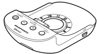
● Handset (IS301) 1
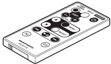
● Remote controller (RC001IS).... 1
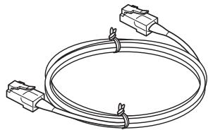
● IS-LINK cables (CAT5/LAN straight-type cables) ... 2
natural_image
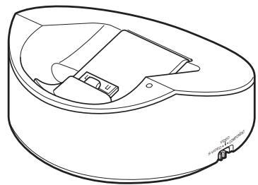
Pure electrical circuit lines without any symbols● Base unit (IS301DS)....1
natural_image
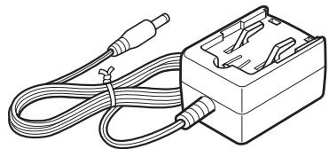
Line drawing of a mechanical component with internal parts and mounting features (no text or symbols)● AC adaptors (for the base unit and extender) .. 2
natural_image
Line drawing of a cable and plug assembly with no text or symbols● AV cable 1
- Remote cable....1
- USB cable .... 1
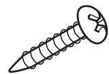
● Wall-mounting screws....4
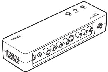
● Extender (IS301RX)....1
natural_image
Line drawing of a portable electronic device with ports and connectors (no text or symbols)● Power plugs for the AC adaptors
- For the U.S.A./Japan....2
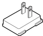
- For Europe .... 2

-
User Guide....1
● Warranties -
For Canada....1
- For the U.S.A. 1
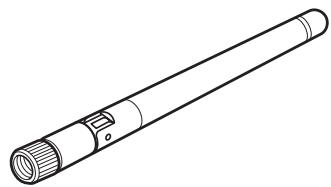
- Antenna for the extender .... 1
natural_image
Line drawing of a cylindrical device with a flanged end and internal ports (no text or symbols)NAMES AND FUNCTIONS
HANDSET (IS301)
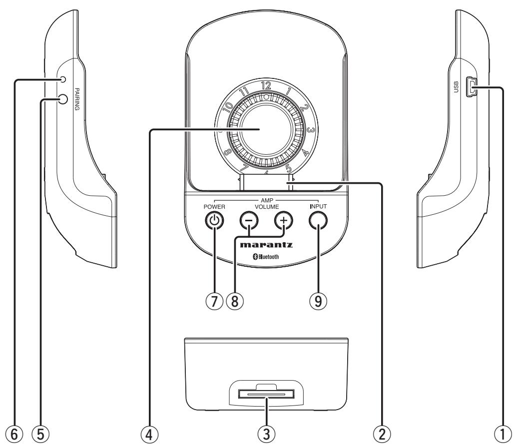
① USB connector
Connect your PC, using the supplied USB cable. Synchronizing the iPod with iTunes is possible with your iPod docked in the handset.
② iPod docking connector
Connect the docking connector of the iPod.
③ Base connector
Connect the Handset connector of the base unit.
④ Thickness adjustment knob
Turn this knob to adjust the thickness, according to the thickness of your iPod product. Inappropriate thickness adjustment may result in damage to the connectors.
For details, see "CONNECTING YOUR iPOD WITH THE HANDSET" (page 8).
⑤ PAIRING button
Use this button to establish Bluetooth connection with the extender.
⑥ PAIRING indicator
This indicates connection status with the extender with lighting/flashing and colors.
⑦ POWER button (AMP control buttons)
This button turns ON/OFF the Marantz amplifier/receiver that is remotely connected with the extender.
⑧ VOL +/- buttons (AMP control buttons)
These buttons increase/decrease the volume of the Marantz amplifier/receiver that is remotely connected with the extender.
⑨ INPUT button (AMP control buttons)
This button switches the input sources of the Marantz amplifier/AV receiver that is remotely connected with the extender.
(Some products do not correspond to this function.)
NAMES AND FUNCTIONS
BASE UNIT (IS301DS)
TOP VIEW
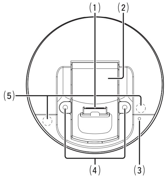
SIDE AND BOTTOM VIEWS
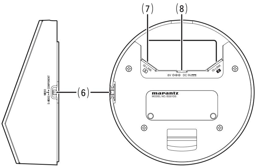
(1) Handset connector
Connect the handset here.
Note
NEVER connect an iPod directly with this connector, because the shape of this connector is different from the docking connector of the iPods.
(2) Handset holder
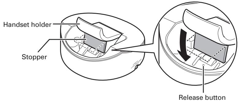
When the base unit is mounted on a wall, raise this holder. For details, see INSTALLATION PROCEDURES FOR THE BASE UNIT (page 13).
(3) Power indicator
This indicator lights when power is supplied from the AC adaptor or when the base unit is connected with the powered extender via the IS-LINK cable. It flashes when an infrared signal from the remote controller is received.
(4) Holes for wall mounting
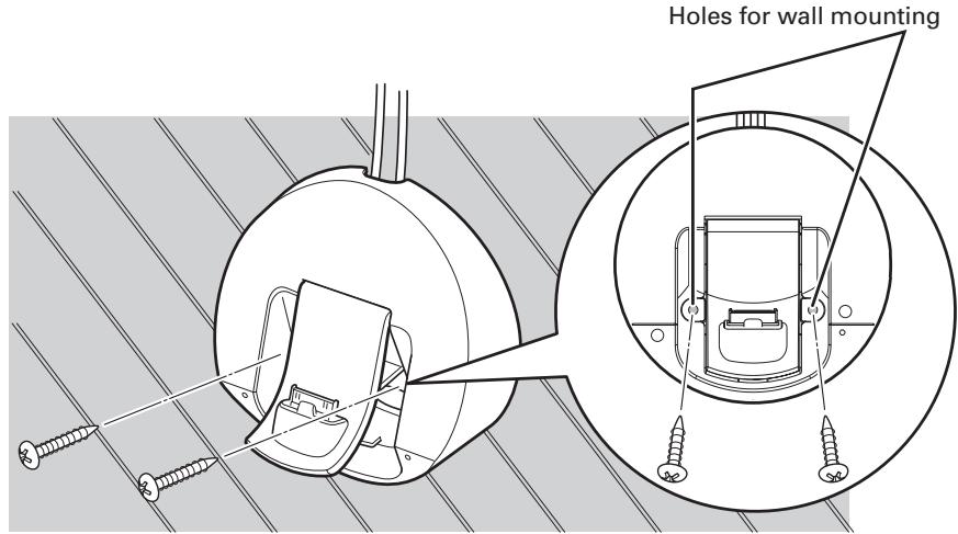
Use these holes when mounting the base unit on a wall.
(5) Infrared signal reception window
This is the reception window for infrared signals from the remote controller.
(6) Video selection switch
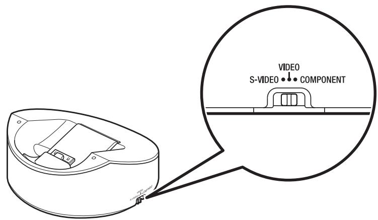
Select video signals (S-VIDEO/VIDEO/COMPONENT) that are output from the extender. If the Video selection switch is switched during video playback, the output signal may not be switched, depending on the type of iPods being connected. In such a case, go back to the MENU screen then restart video playback.
(7) IS-LINK A/V terminals
Used to connect the base unit and the extender via the supplied IS-LINK cables.
Before connection, unplug the power cord then check that the connections to the IS-LINK A and V terminals are properly made.
TRANSMISSION SIGNALS VIA IS-LINK A
- Audio signal
- Remote control signal
- Power
TRANSMISSION SIGNALS VIA IS-LINK V
- Video signal
- External control signal
(8) AC adaptor terminal
Connect the supplied AC adaptor.
If the base unit and the extender is connected by the IS-LINK A connection, power will be supplied from the extender.
Therefore, it is not required to connect the AC adaptor to the base unit.
NAMES AND FUNCTIONS
EXTENDER (IS301RX)
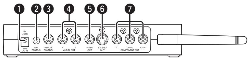
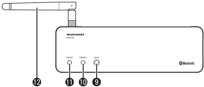
natural_image
Pure technical diagram of a mechanical or electrical component with no text, numbers, or symbols① AC adaptor terminal
Connect the supplied AC adaptor.
② EXT. CONTROL terminal
Used to connect an external control system.
③ REMOTE CONTROL terminal
Connect to a Marantz product equipped with a remote control terminal.
4 AUDIO OUT L/R terminals
Connect to the audio input terminals of an amplifier/receiver/TV.
⑤ VIDEO OUT terminal
Connect to the video input terminal of a receiver/TV.
⑥ S-VIDEO OUT terminal
Connect to the S-VIDEO input terminal of a receiver/TV.
⑦ COMPONENT (Y, Cb/Pb, Cr/Pr) VIDEO OUT terminals
Connect to the component video input terminals of a receiver/TV.
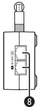
8 IS-LINK A/V terminals
Used to connect the base unit and the extender via the supplied IS-LINK cables.
Connect the supplied IS-LINK cables.
Before connection, unplug the power cord then check that the connections to the IS-LINK A and V terminals are properly made.
TRANSMISSION SIGNALS VIA IS-LINK A
- Audio signal
- Remote control signal
- Power
TRANSMISSION SIGNALS VIA IS-LINK V
- Video signal
• External control signal
⑨ MODE button
Use this button to establish a wireless connection between the handset and extender.
10 PAIRING indicator
This indicates connection status with the handset with lighting/flashing and colors.
11 POWER indicator
This indicator lights when the AC adaptor is connected to the extender.
12 Antenna
This is an antenna for wireless communication. At shipment, this antenna is packed separately from the extender. For details on how to mount on the extender, see page 7.
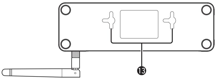
⑬ Holes for wall mounting
Use these holes when mounting the extender on the wall.
BASIC OPERATIONS
PREPARATION OF THE AC ADAPTOR
POWER PLUG ATTACHMENT PROCEDURES
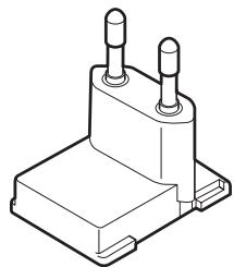
- Attach the supplied power plug to the supplied AC adaptor, by sliding the plug in the direction of the arrow.
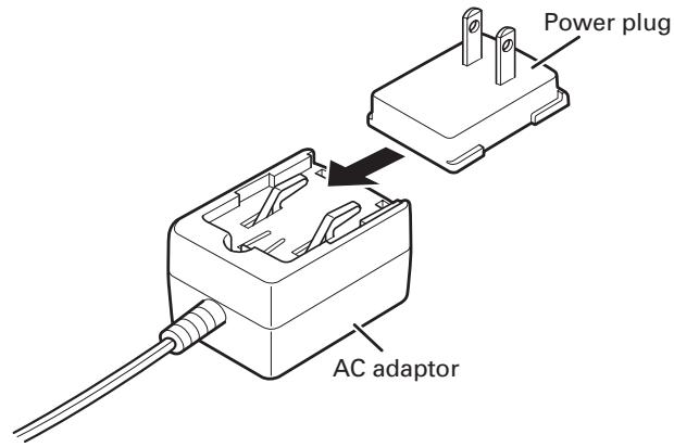
● For the U.S.A./Japan
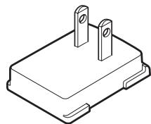
For Europe
natural_image
Isometric line drawing of a mechanical component with two cylindrical pins (no text or symbols)Notes
- NEVER use the power plug with equipment other than the supplied AC adaptor.
- Connect the AC adaptor to the wall outlet nearest its installation position.
- Before plugging/unplugging the cable of the AC adaptor to/from the AC input terminal, make sure that the power cord is unplugged from the wall outlet.
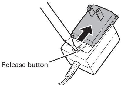
- If an improper power plug is attached to the AC adaptor, detach it by pressing the release button with a pointed object, such as a pen, as shown in the figure below.
ON POWER SUPPLY TO THIS UNIT
A power switch is not provided for this unit.
After connecting the AC adaptor to this unit, when the AC adaptor is plugged into a wall outlet, power is supplied to this unit.
WIRELESS CONNECTION
WHAT ARE AVAILABLE WHEN WIRELESS CONNECTIONS ARE USED
- Audio playback
- Remote operations of a Marantz amplifier or receiver, using the AMP control buttons on the handset
- Use of an iPod with the handset detached from the base unit
- Control of a Marantz amplifier, using the supplied remote controller (When the handset is connected with the base unit)
BEFORE CONNECTION
Notes
- If the cable is connected to the IS-LINK terminals, wireless connection will not be enabled.
- If an iPod and the handset are used detached from the base unit, the handset will be powered by the built-in battery of the iPod. This makes it difficult to use them for a long duration.
The operable time will differ, depending on the type of iPod products you use. - What are NOT available when wireless connections are made are as follows:
- Video playback
- Use of the base unit as an infrared signal receiver for controlling a Marantz product
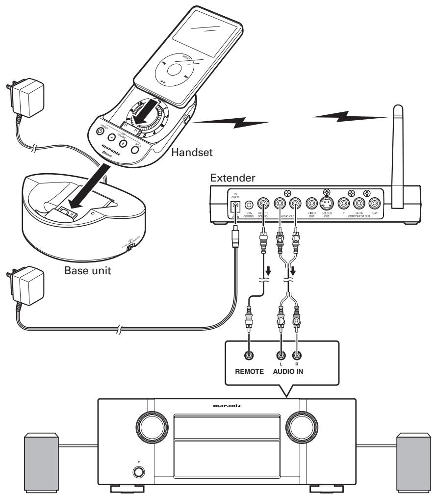
① CONNECTING THE EXTENDER AND AN AMPLIFIER
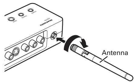
- Attach the supplied antenna to the antenna terminal of the extender.
- Connect the AUDIO OUT terminals of the extender with the line input terminals of an amplifier/receiver, via the supplied AV cable.
- If you wish to remotely control the connected amplifier/receiver using the Marantz remote control terminals, connect the REMOTE CONTROL terminals of both pieces of equipment via the supplied remote cable.
This connection makes it possible to operate the Marantz amplifier/receiver with the AMP control buttons (POWER button, VOLUME +/- buttons, and INPUT button) on the handset.
- Connect the supplied AC adaptor to the AC adaptor terminal of the extender. (For details, see "PREPARATION OF THE AC ADAPTOR". (page 6))
BASIC OPERATIONS
② CONNECTING THE HANDSET TO THE BASE UNIT
- Attach the handset to the base unit, as shown in the figure below.
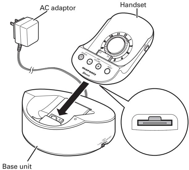
- Connect the supplied AC adaptor to the AC adaptor terminal of the base unit. (For details, see "PREPARATION OF THE AC ADAPTOR". (page 6))
③ CONNECTING iPod TO THE HANDSET
- Turn the Thickness adjustment knob of the handset, according to the type of your iPod. For details on the positions of the knob, see the "LIST OF THICKNESS ADJUSTMENT KNOB POSITIONS" table.
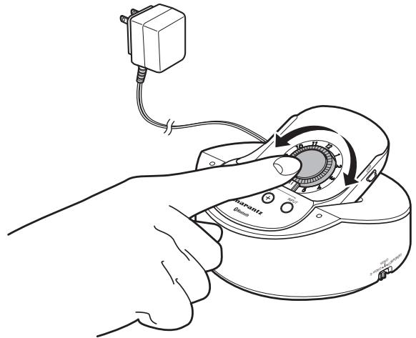
LIST OF THICKNESS ADJUSTMENT KNOB POSITIONS
| iPod | Positions of the knob | iPod | Positions of the knob |
iPod touch 1G/2G  | 3 | iPod 4G Photo 20GB/30GB | 7 |
iPod classic 160GB  | 9 | iPod 4G Photo 40GB/60GB | 12 |
iPod classic 80GB/120GB  | 4 | iPod 4G 20GB | 6 |
iPod 5G Video 60GB/80GB  | 9 | iPod 4G 40GB | 11 |
| iPod 5G Video 30GB [8DS2] | 4 | iPod nano 1G/2G/3G/4G | 1 |
| G in the table stands for Generation of iPod products. Example: iPod 5G (iPod, 5th generation) | iPod mini | 7 | |
Notes
natural_image
Pure technical line drawing of a rectangular device with internal components and dimension lines (no text or symbols)- The location of the docking connector on an iPod product varies, according to the generation, type, and capacity of products.
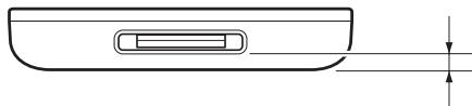
- Before attaching an iPod, be sure to turn the Thickness adjustment knob to an appropriate position. If an iPod is plugged/unplugged without adjusting the thickness to an appropriate position, damage to the connectors may result.

natural_image
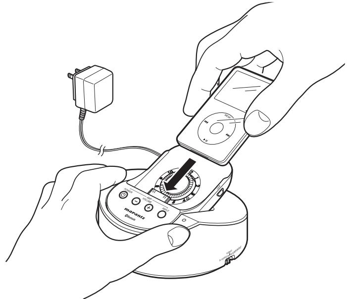
Three technical line drawings of a curved mechanical component with mounting holes, shown in different angles (no text or symbols)2. Securely connect the iPod to the docking connector of the handset.
natural_image
Line drawing of hands using a multimeter to interact with a device, no text or symbols presentNotes
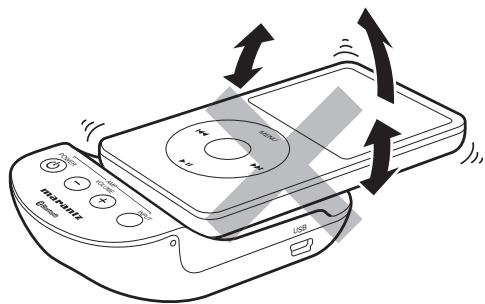
- When attaching/detaching the iPod to/from the handset, be sure to grip the handset by hand. Improper attaching/detaching of the iPod may damage the connectors.
- When attaching/detaching the iPod to/from the handset, be sure NOT to twist the iPod, as this may damage the connectors.
- Be careful NOT to tilt the iPod forward during use, as this may damage the connectors.
natural_image
Illustration of a CD-ROM device with scroll arrows indicating rotation or sound waves (no text or symbols)- NEVER insert the iPod into the handset with its protective case attached. Doing so may result in poor connection or damage to the connectors.
- Do not use other accessories, such as an FM transmitter or microphone, with the handset. This may result in a malfunction.
- Marantz accepts no responsibility whatsoever for any loss or damage of iPod data resulting from the use of an iPod product connected with this unit.
④ MAKING WIRELESS CONNECTION BETWEEN THE HANDSET AND EXTENDER
For wireless connection between the handset and extender, pairing is required for mutual authentication and registration. Perform pairing, according to the procedures shown below.
PAIRING PROCEDURES
- Attach the handset to the base unit.
- Locate the extender near the base unit and connect the AC adaptors to each of them.
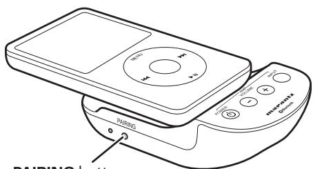
- Press and release the PAIRING button of the handset and the MODE button of the extender once. The PAIRING indicator will light in red (connection not established).
PAIRING button
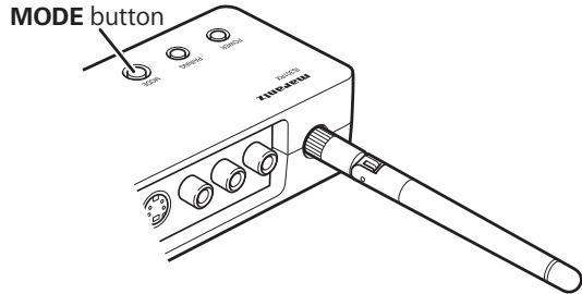
- Press and hold the PAIRING button of the handset and the MODE button of the extender for 5 seconds or more until the PAIRING indicator starts alternate flashing in blue and red at intervals of 0.5 second. The handset and extender will search for each other's pairing device.
- After searching and pairing are completed, the color of the flashing PAIRING indicator at intervals of 0.5 second will change to blue. The unit will automatically start preparing for wireless audio playback.
When the PAIRING indicator starts flashing in blue at intervals of 5 seconds, preparation for audio playback is completed.
Play back the iPod.
Notes
- Even if wireless connection is interrupted for some reason, such as radio wave interference or power failure, reconnection will automatically be performed.
- If reconnection is not possible, the PAIRING indicator will light in red.
In such a case, press the PAIRING button of the handset twice to disconnect then press the same button again so that the PAIRING indicator lights in red.
Then press the PAIRING button once again. The PAIRING indicator will start flashing in blue at intervals of 0.5 second to start preparing for reconnection. When the PAIRING indicator starts flashing in blue at intervals of 5 seconds, preparation for reconnection is completed.
IN A CASE WHERE THE IPOD AND HANDSET ARE USED DETACHED FROM THE BASE UNIT
Depending on the type of iPod, the handset may not enter Wireless mode when the iPod is started. In such a case, detach the iPod from the handset with the iPod's power on then reconnect it to the handset.
BASIC OPERATIONS
IS-LINK (WIRED) CONNECTIONS
WHAT ARE AVAILABLE WHEN IS-LINK CONNECTIONS ARE USED
• Audio and video playback
- Remote operations of a Marantz amplifier or receiver, using the AMP control buttons on the handset
- Remote control of a Marantz amplifier, using the supplied remote controller
- Use of the base unit as an infrared signal receiver for controlling a Marantz product
BEFORE CONNECTION
Notes
- What are NOT available when IS-LINK connections are made are as follows:
- Video playback of an iPod when the iPod and the handset are detached from the base unit
- During IS-LINK connection, power is supplied to the base unit from the extender. Therefore, it is not necessary to connect the AC adaptor to the base unit.
- Three types of video signals are output from the extender. Set the Video selection switch of the base unit according to the video output signal to be used.
- If the Video selection switch is switched during video playback, the output signal may not be switched, depending on the type of iPods being connected. In such a case, go back to the MENU screen then restart video playback.
- Some iPods do not support component video output.
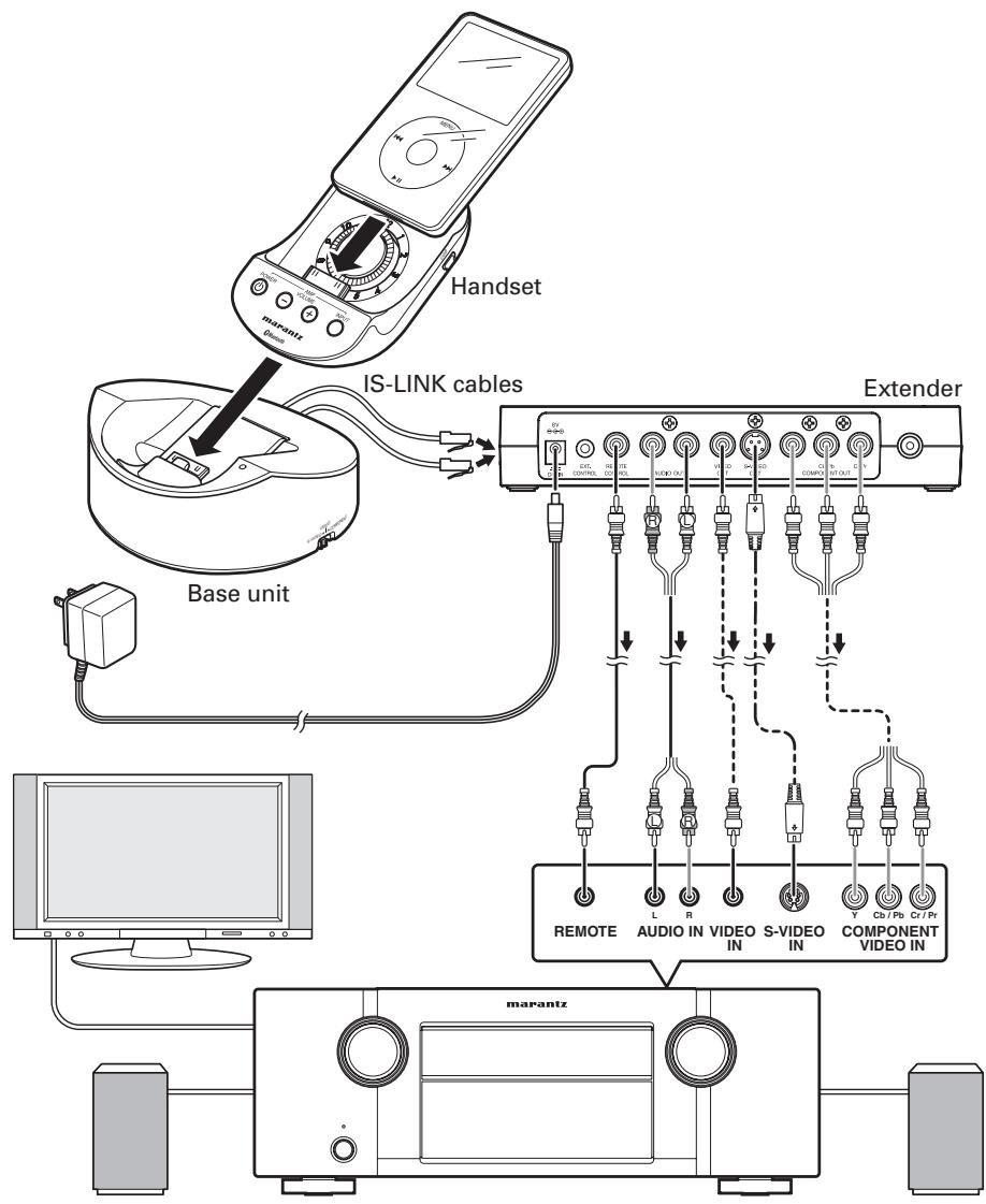
flowchart
graph TD
    A["Handset"] --> B["IS-LINK cables"]
    B --> C["Base unit"]
    C --> D["External Components"]
    D --> E["Remote Audio In Video In S-Video In COMPONENT Video In"]
    E --> F["Computer"]
① CONNECTING THE EXTENDER AND AN AMPLIFIER
- Connect the AUDIO OUT terminals of the extender with the line input terminals of an amplifier/receiver, via the supplied AV cable.
- Connect the video input terminal of an amplifier/receiver/TV to one of the VIDEO OUT terminals (VIDEO/S-VIDEO/COMPONENT) of the extender, using an appropriate video cable.
The S-VIDEO and component video cables are not supplied with this unit. Use a commercially available video cable.
Note
NEVER connect different video cables simultaneously, as this may result in disturbed video signals or a failure.
- If you wish to remotely control the connected equipment using the Marantz REMOTE CONTROL terminals, connect the REMOTE CONTROL terminals of the connected equipment and the extender with the supplied remote cable.
② CONNECTING THE BASE UNIT AND EXTENDER WITH IS-LINK
- Connect the base unit and extender with two supplied IS-LINK cables.
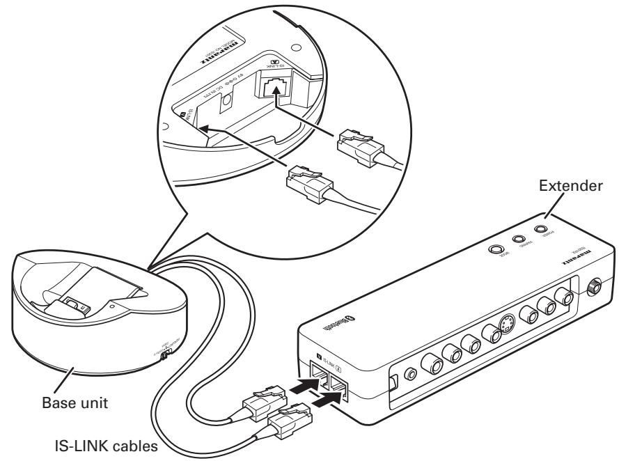
- Connect the supplied AC adaptor to the AC adaptor terminal of the extender. (For details on preparation of the AC adaptor, see page 6.)
③ CONNECTING THE HANDSET TO THE BASE UNIT
For details on connection, see page 8.
- During IS-LINK connection, power is supplied to the base unit from the extender. Therefore, it is not necessary to connect the AC adaptor to the base unit.
④ CONNECTING AN iPod TO THE HANDSET
For details on connection, see page 8.
ADVANCED OPERATIONS
CONNECTING THE EXTENDER WITH OTHER BLUETOOTH DEVICES
The extender can be connected with other Bluetooth devices with the A2DP profile.
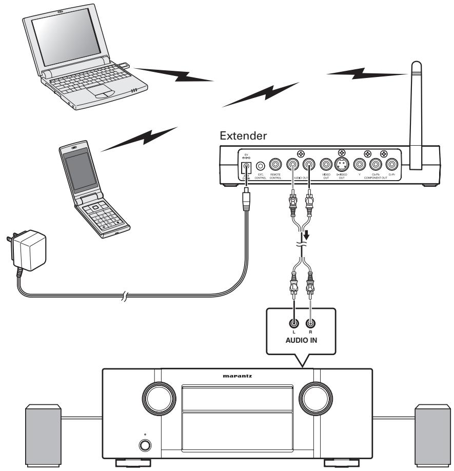
flowchart
graph TD
    A["Laptop"] -->|Wireless Link| B["Extender"]
    C["Laptop"] -->|Wireless Link| B
    D["Marantz"] -->|Audio In| B
    B --> E["Audio IN"]
    B --> F["AUDIO IN"]
    B --> G["Audio IN"]
    style A fill:#f9f,stroke:#333
    style C fill:#f9f,stroke:#333
    style D fill:#f9f,stroke:#333
    style B fill:#ccf,stroke:#333
    style E fill:#cff,stroke:#333
    style F fill:#cff,stroke:#333
    style G fill:#cff,stroke:#333
- When the handset and extender are connected wirelessly, press the PAIRING button of the handset. The PAIRING indicator will light in red, and wireless communication on the handset side will stop.
Let the handset for 10 seconds.
- Locate other Bluetooth device near the extender.
- Press the MODE button of the extender once. The PAIRING indicator will light in red. Refer to the operation manual of your Bluetooth device for pairing procedures of the connected Bluetooth device.
- Hold the MODE button pressed for 5 seconds or more until the PAIRING indicator starts alternate flashing in blue and red at intervals of 0.5 second. The unit will search for a device for pairing.
- After a device to be paired is found, the color of the flashing PAIRING indicator at intervals of 0.5 second will change to blue. The unit will automatically start preparing for wireless audio playback.
If passcode input is requested on the other Bluetooth device, enter "0000".
- After connection with the A2DP/AVRCP profiles is established, the PAIRING indicator starts flashing in blue at intervals of 5 seconds, and preparation for playback is completed.
Notes
- Once pairing is completed, further pairing operation is not required for the same devices from the next Bluetooth communication.
- Up to 8 Bluetooth devices that have A2DP/AVRCP profiles can be paired with this unit.
- If the number of paired devices exceeds 8, each time a new device is paired, the already paired devices are cleared from the oldest one.
- Connection of the handset with other Bluetooth devices is possible in the same way as with the handset.
- Bluetooth and its logo are trademarks of Bluetooth SIG, Inc. and Marantz uses them based on the appropriate license.
- Connection with all existing Bluetooth devices is not guaranteed.
MOUNTING ON A WALL
This unit can be mounted on a wall. Read the precautions described below and carefully install the unit. For safety, it is recommended to delegate mounting to a professional contractor.
NOTES ON INSTALLATION LOCATION
- Before installation, check the material and construction compatibilities of the installation location. If they are not assured, the unit may fall, which may result in personal injury.
- NEVER mount the unit in a location subject to lot of vibration, shock, or strong force. Doing so may cause a fall or damage of the unit and may result in personal injury.
- Before installation, make sure that there is no electrical wiring nor piping inside the wall.
PRECAUTIONS ON INSTALLATION
- NEVER modify the unit or use it in an inappropriate way. Dropping the unit may result in personal injury.
- The supplied wall-mounting screws are for wooden walls. If the unit is to be mounted on a wall other than wooden walls, procure commercially available screws suitable for the structure and materials of the wall.
- Secure the screws tightly when mounting the base unit. Loose screws may cause an accident, such as falling of the unit. NEVER leave the screws not securely tightened.
- NEVER mount the unit so that it will protrude away from an exterior corner of the wall. Doing so may lead to personal injury, because a person or object may bump into the unit.
- Marantz accepts no responsibility whatsoever for any accident or damage resulting from improper mounting or handling.
- When mounting, be careful not to pinch your fingers or hands.
- Make sure that the two screws are securely tightened in the holes for wall mounting of the extender.
INSTALLATION PROCEDURES FOR THE BASE UNIT
- Remove the handset from the base unit.
- Push the stopper holder from through the hole on the bottom of the base unit.
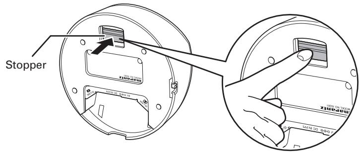
- With the handset holder raised, push the stopper down so that it clicks and locks in place.
- Connect the cables.
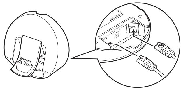
natural_image
Technical illustration of a device's internal components, showing a close-up view and cable installation (no text or symbols)ADVANCED OPERATIONS
- Secure the base unit on the wall, by tightening the screws of the size shown in the figure below, using a screwdriver, through the holes for wall mounting of the base unit.

Notes
- Check that the unit is securely fixed on the wall.
- Securely connect the cables to the unit.
- To detach the unit from the wall and use it on a table, return the stopper to its original position, by holding the release button pressed, then return the handset holder to its original position.
INSTALLATION PROCEDURES FOR THE EXTENDER
The extender can be mounted on a wall or a rack, using the two holes provided on the bottom of the extender.
The extender can be installed in either a horizontal or vertical orientation. Select the orientation according to the installation conditions.
Notes
- Reception sensitivity varies, depending on the direction of the antenna. Before installing the extender, adjust the orientation of the antenna and check that radio waves can be securely received.
- The supplied wall-mounting screws are for wooden walls. If the unit is to be mounted on a wall other than wooden walls, procure commercially available screws suitable for the structure and materials of the wall.
-
Before mounting on a wall, read the precautions thoroughly.
-
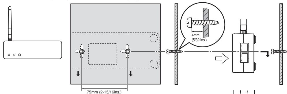
Procure two screws that are suitable for the strength and material of the wall surface. The size of the screws is shown in the figure below.

- The relative positions of the holes for wall mounting of the extender and screw-mounting positions are shown in the figure below. (Use the template provided on the last page of this manual.)
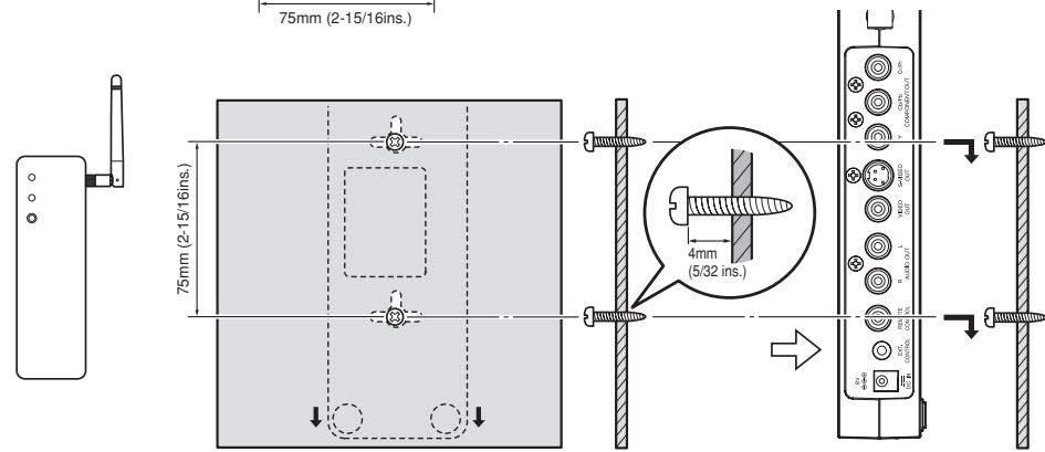
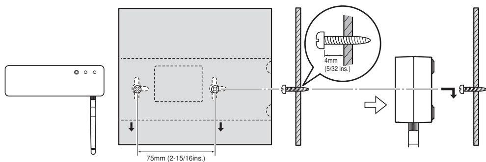
Note
When tightening the screws in the wall surface, leave a gap between the wall surface and the head of the screw, as shown in the figure.
- Place the extender so that the two screws in the wall are inserted through the holes for wall mounting of the extender, then slide the extender downward to secure it on the wall.
- After securing the extender on the wall, connect the AC adaptor and other cables.
Notes
- Check that the extender is securely fixed to the wall.
-
Securely connect the AC adaptor and cables to the extender.
-
To detach the extender from the wall, lift it upward then pull out toward you.
USE OF THE REMOTE CONTROLLER (RC001IS)
NAMES AND FUNCTIONS OF THE REMOTE CONTROLLER
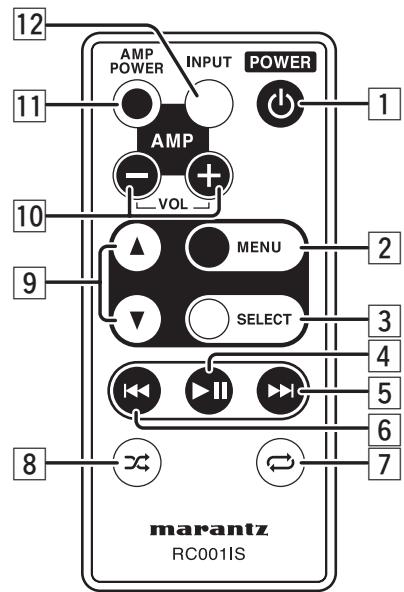
1 POWER button
Used to turn the power to the iPod on or off.
2 MENU button
This button operates in the same way as the MENU button on the iPod.
3 SELECT button
This button operates in the same way as the Select button on the iPod.
4 ▶II (Playback/pause) button
This button operates in the same way as the ▶II button on the iPod.
5 ▶▶▶ (Skip) button
Press this button once to skip to the next content.
6 |◀◀ (Back skip) button
Press this button once to return to the beginning of the content being played back.
Press this button twice consecutively to return to the previous content.
7 Repeat button
Used to change the Repeat mode of the iPod. (One song → All songs → Off)
8 Shuffle button
Used to change the Shuffle mode of the iPod. (Songs → Albums → Off)
9 ▲▼ buttons
These buttons operate in the same way as the Up (▲) and Down (▼) buttons on the iPod.
These buttons are also used to move the cursor. (Volume adjustment of the iPod is excluded.)
10 AMP VOL +/- buttons
Used to increase/decrease the volume of a Marantz amplifier/receiver remotely connected with this unit.
11 AMP POWER button
Used to turn ON/OFF a Marantz amplifier/receiver remotely connected with this unit.
12 AMP INPUT button
Used to switch the input sources of a Marantz amplifier/receiver remotely connected with this unit. (Some models cannot be remotely controlled with this button.)
Note
Operations of the remote controller may differ, depending on the generation and model of the iPod products.
ADVANCED OPERATIONS
BEFORE USING THE REMOTE CONTROLLER
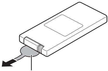
A lithium battery comes installed in the remote controller.
Before use, pull out the insulation sheet.
natural_image
Diagram of a rectangular electronic device with a key inserted, showing internal components and an arrow indicating direction (no text or symbols present)Insulation sheet
BATTERY REPLACEMENT
If the battery of the remote controller is exhausted, the operable distance of the remote controller becomes extremely short. In such a case, replace the battery with a new one.
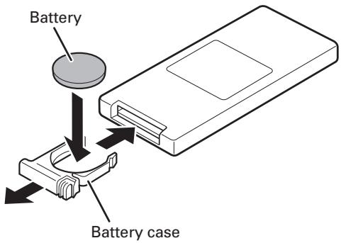
- Pull out the battery case, referring to the figures depicted on the rear panel of the remote controller.
- Pull out the old lithium battery from the battery case and insert a new one. Place the battery so that the + (positive) side faces upward.
- Replace the battery case in its original position.
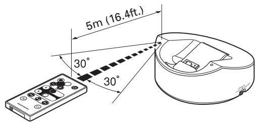
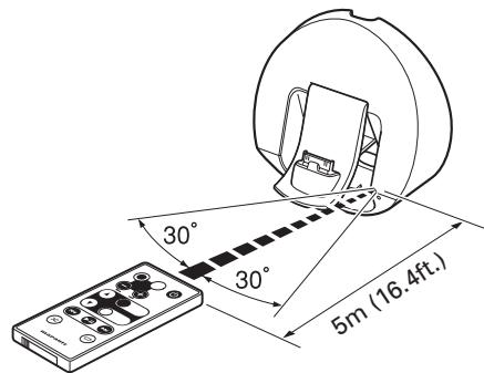
The operable range of the remote controller is shown in the figure below.
Notes On Use
- Do not allow direct sunlight, an inverter fluorescent light or other strong light to shine onto the unit's infrared signal reception window (remote sensor). Doing so may disable operation of the remote controller.
- Note that operating the remote controller may cause other devices operated by infrared rays to be operated by mistake.
- The remote controller cannot be operated if the line of sight between the remote controller and the unit's remote sensor is obstructed.
- Do not place any objects on top of the remote controller. Doing so may cause one or more buttons to be held down, which will cause the battery to run down.
CAUTIONS ON HANDLING BATTERIES
Misuse of the lithium battery can result in heat buildup, ignition, or rupture. Bear in mind the following points when using or replacing batteries.
- The supplied battery is for testing the functionality of the remote controller.
- Use a CR2032 lithium battery.
• NEVER recharge the battery. - Do not handle the battery roughly or deconstruct the battery.
- When replacing the battery, place it with correct polarity (+ and -).
- Do not leave the battery in a place subject to high temperature, such as a place subject to direct sunlight.
- Keep the battery in a place beyond infants' or children's reach. If a battery is swallowed, consult a physician immediately.
- If electrolyte has leaked, discard the battery immediately. Be careful when handling such a battery, because if the electrolyte is attached to your skin or clothes, you may be burned. If it is accidentally attached, immediately wash with tap water then consult a physician.
- When a battery which is no longer required is to be discarded, insulate it with tape, etc. and dispose of it in a place without fire, by following the directions (regulations) laid down by the local authorities in the area concerned for its disposal.
TROUBLESHOOTING
Be sure to check the items in the following list if you experience problems. If checking the following items does not resolve your problem, please contact the retail store where you purchased your product, your nearest Marantz authorized dealer or the Marantz Service Center in your country.
| Symptom | Possible cause | Resolution |
| No sound or video | The iPod is not properly connected with the iPod docking connector of this unit. | Disconnect the iPod from the docking connector then connect it again. |
| No playback from the iPod | Play back the iPod. | |
| The cables connected to this unit are not fully plugged in. | Check the cable connections. | |
| The AC adaptor is not securely connected to this unit or is unplugged from the wall outlet. | Securely connect the AC adaptor to the unit and plug it into the wall outlet. | |
| No sound | Pairing for Bluetooth communication has not been properly completed. | Perform pairing for Bluetooth (wireless) communication again. |
| The receiver or amplifier connected to this unit is not turned on. | Turn the receiver or amplifier on. | |
| The input terminal on the receiver or amplifier to which the output signal from the iPod is fed is not properly selected. | Check the input of the receiver or amplifier. | |
| The volume of the receiver or amplifier to which this unit is connected is very low. | Increase the volume of the receiver or amplifier. | |
| No video | Wireless connection is used. | IS-LINK connections are required. |
| The video output setting of the iPod is not proper. | Check the video output setting of the iPod. | |
| The setting of the Videoselection switch on the base unit is inappropriate. | Set the Video selection switch, according to the video output terminal to which the video cable is connected. | |
| Distorted sound | There is a device, such as a wireless LAN or microwave, that uses radio waves in the same frequency band (2.4-GHz) as this unit. | Change the locations of the handset and extender. |
| No operation with the supplied remote controller | The iPod is not properly connected with the iPod docking connector of this unit. | Disconnect the iPod from the docking connector then connect it again. |
| There is an object that interrupts infrared signals between the unit and the remote controller. | Remove any object between the unit and the remote controller. | |
| The remote control cable is not properly connected. | Check the cable connections. |
OTHERS
CLEANING OF EQUIPMENT EXTERNAL SURFACES
The exterior finish of your unit will last indefinitely with proper care and cleaning, Never use scouring pads, steel wool, scourging powders or harsh chemical agents (e.g., lye solution), alcohol, thinner, benzine, insecticide or other volatile substances as these will mar the finish of the equipment. Likewise, never use cloths containing chemical substances. If the equipment get dirty, wipe the external surfaces with a soft, lint-free cloth.
If the equipment becomes heavily soiled:
- dilute some washing up liquid in water, in a ratio of one part detergent to six parts water.
- dip a soft, lint free in the solution and wring the it is damp.
- wipe the equipment with the damp cloth.
- dry the equipment by wiping it with a dry cloth.

REPAIRS
Only the most competent and qualified service technicians should be allowed to service the factory-trained warranty station personnel have the knowledge and special facilities needed for repair and calibration of this precision equipment.
After the warranty period has expired, repairs will be performed for a charge if the equipment can be returned to normal operation.
In the event of difficulty, refer to your dealer or write directly to the nearest location to you that is listed on the Marantz Authorized Service Station list. If writing, please include the model and serial number of the equipment together with a full description of what you think is abnormal about the equipment's behavior.
OTHERS
SPECIFICATIONS
IS301 (HANDSET)
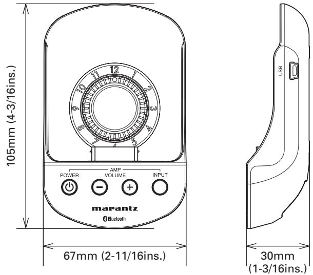
Power supply ....5 V DC from iPod accessory power supply Weight ....68g/2.4ozs External dimensions (W/H/D)....67 × 105 × 30 mm (2-11/16 × 4-3/16 × 1-3/16 ins.) Terminals....USB mini B
IS301DS (BASE UNIT)
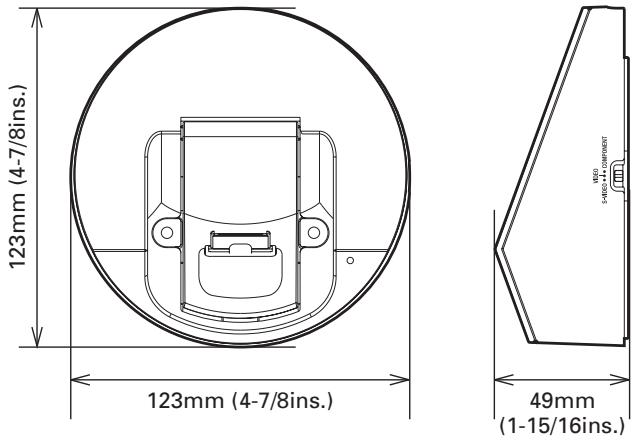
Power supply ....8 V DC IN (from the dedicated AC adaptor) Weight ....230g/8.1ozs External dimensions (W/H/D)....123 × 123 × 49 mm (4-7/8 × 14-7/8 × 1-15/16 ins.) Terminals....RJ-45 ×2
IS301RX (EXTENDER)
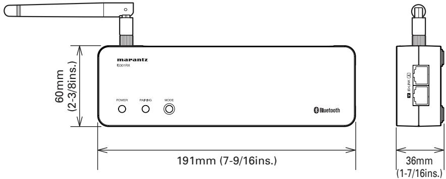
Power supply ....8 V DC IN (from the dedicated AC adaptor) Weight ....230g/8.1ozs External dimensions (W/H/D)....191 ×60 ×36 mm (7-9/16 ×2-3/8 ×1-7/16 ins.) Terminals.....Video output (S-VIDEO ×1, VIDEO ×1, COMPONENT ×1) .....Analog audio ×1, Remote terminal ×1, RS-232C terminal ×1, RJ-45 ×2
BLUETOOTH-RELATED (IS301/IS301RX)
Communication method ....Bluetooth ver. 2.1 + EDR Transmission output....Bluetooth Power Class 2 Maximum transmission distance....Line-of-sight distance approx. 10 m (32.8ft.)(*1) Transmission frequency band ....2.400 GHz to 2.4835 GHz Modulation method....FH-SS Supporting Bluetooth profiles....A2DP (Advanced Audio Distribution Profile), AVRCP (Audio Video Remote Control Profile) Supporting CODEC....SBC (Subband Codec) Supporting content protection....SCMS-T (Only for the IS301RX) Passcode....0000
(*1) The transmission distance is an approximate value. It may vary, depending on the ambient environment.
- The Bluetooth® word mark and logos are registered trademarks owned by Bluetooth SIG, Inc. and any use of such marks by D&M Holdings Inc. is under license. Other trademarks and trade names are those of their respective owners.
- Connection with all existing Bluetooth devices is not guaranteed.
SUPPLIED AC ADAPTOR
Power supply 100 V - 240 V AC (50 Hz/60 Hz) 1A
The specifications and external appearance of this unit may be changed without prior notification for the purpose of improvement.
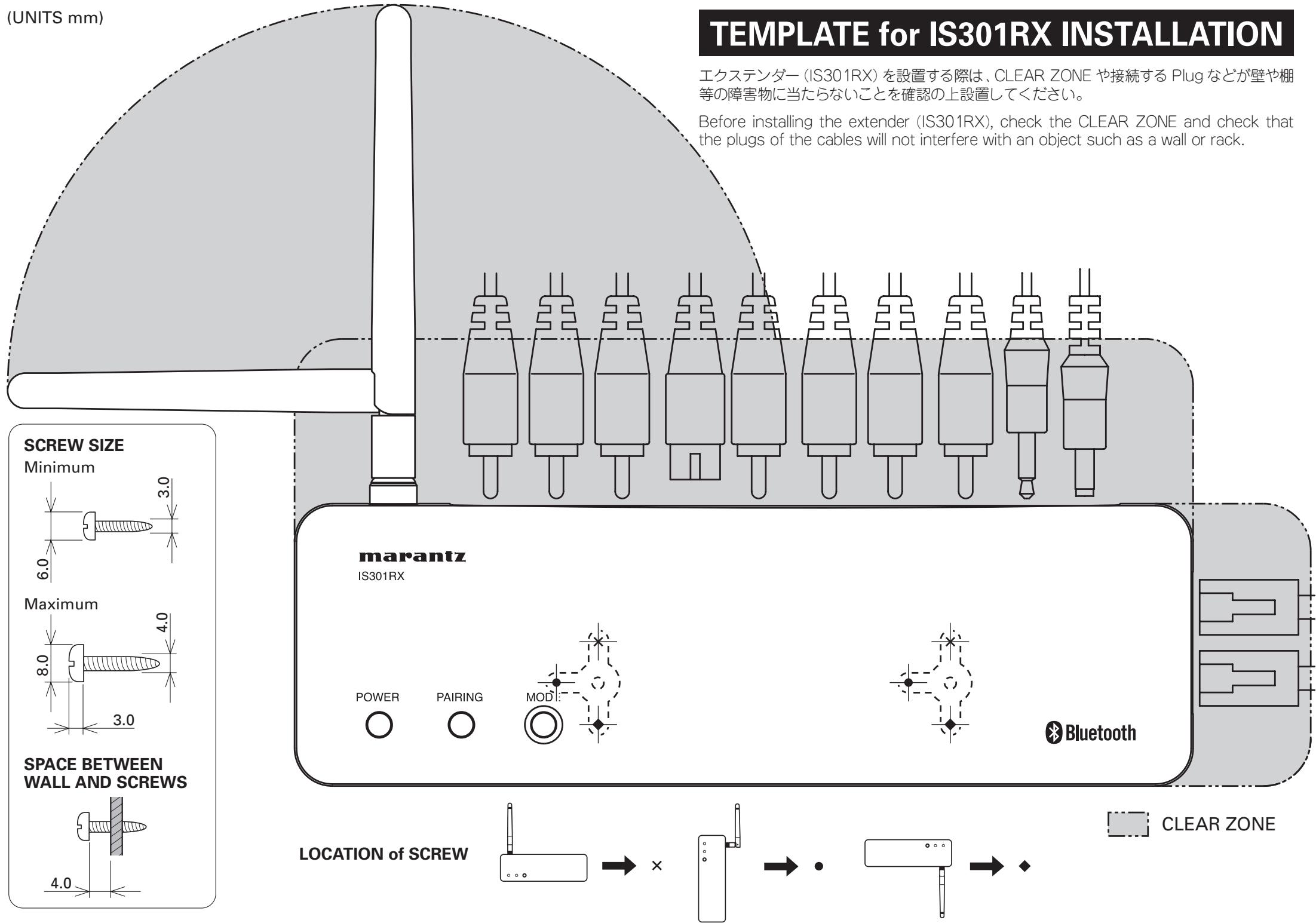
TEMPLATE for IS301RX INSTALLATION
Before installing the extender (IS301RX), check the CLEAR ZONE and check that the plugs of the cables will not interfere with an object such as a wall or rack.
www.marantz.com
You can find your nearest authorized distributor or dealer on our website.
marantz ^® is a registered trademark.

- marantz®
- Wireless Dock for iPod IS301
- CAUTION
- WARNING
- TO REDUCE THE RISK OF FIRE OR ELECTRIC SHOCK, DO NOT EXPOSE THIS APPLIANCE TO RAIN OR MOISTURE.
- NOTE:
- IMPORTANT SAFETY INSTRUCTIONS
- READ BEFORE OPERATING EQUIPMENT
- ENGLISH
- WARRANTY
- RETAIN YOUR PURCHASE RECEIPT
- IMPORTANT
- FOR U.K. ONLY
- FRANÇAIS
- GARANTIE
- AVERTISSEMENTS
- 安全上のご注意
- CONTENTS
- FEATURES
- BEFORE USE
- CONNECTABLE iPod PRODUCTS
- Notes
- CHECKING THE PRODUCT AND ACCESSORIES
- NAMES AND FUNCTIONS
- HANDSET (IS301)
- ① USB connector
- ② iPod docking connector
- ③ Base connector
- ④ Thickness adjustment knob
- ⑤ PAIRING button
- ⑥ PAIRING indicator
- ⑦ POWER button (AMP control buttons)
- ⑧ VOL +/- buttons (AMP control buttons)
- ⑨ INPUT button (AMP control buttons)
- BASE UNIT (IS301DS)
- Handset connector
- Note
- Handset holder
- Power indicator
- Holes for wall mounting
- Infrared signal reception window
- Video selection switch
- IS-LINK A/V terminals
- TRANSMISSION SIGNALS VIA IS-LINK A
- TRANSMISSION SIGNALS VIA IS-LINK V
- AC adaptor terminal
- EXTENDER (IS301RX)
- ① AC adaptor terminal
- ② EXT. CONTROL terminal
- ③ REMOTE CONTROL terminal
- AUDIO OUT L/R terminals
- ⑤ VIDEO OUT terminal
- ⑥ S-VIDEO OUT terminal
- ⑦ COMPONENT (Y, Cb/Pb, Cr/Pr) VIDEO OUT terminals
- IS-LINK A/V terminals
- ⑨ MODE button
- PAIRING indicator
- POWER indicator
- Antenna
- ⑬ Holes for wall mounting
- BASIC OPERATIONS
- PREPARATION OF THE AC ADAPTOR
- POWER PLUG ATTACHMENT PROCEDURES
- ON POWER SUPPLY TO THIS UNIT
- WIRELESS CONNECTION
- WHAT ARE AVAILABLE WHEN WIRELESS CONNECTIONS ARE USED
- BEFORE CONNECTION
- ① CONNECTING THE EXTENDER AND AN AMPLIFIER
- ② CONNECTING THE HANDSET TO THE BASE UNIT
- ③ CONNECTING iPod TO THE HANDSET
- Securely connect the iPod to the docking connector of the handset.
- ④ MAKING WIRELESS CONNECTION BETWEEN THE HANDSET AND EXTENDER
- PAIRING PROCEDURES
- IN A CASE WHERE THE IPOD AND HANDSET ARE USED DETACHED FROM THE BASE UNIT
- IS-LINK (WIRED) CONNECTIONS
- WHAT ARE AVAILABLE WHEN IS-LINK CONNECTIONS ARE USED
- ② CONNECTING THE BASE UNIT AND EXTENDER WITH IS-LINK
- ③ CONNECTING THE HANDSET TO THE BASE UNIT
- ④ CONNECTING AN iPod TO THE HANDSET
- ADVANCED OPERATIONS
- CONNECTING THE EXTENDER WITH OTHER BLUETOOTH DEVICES
- MOUNTING ON A WALL
- NOTES ON INSTALLATION LOCATION
- PRECAUTIONS ON INSTALLATION
- INSTALLATION PROCEDURES FOR THE BASE UNIT
- INSTALLATION PROCEDURES FOR THE EXTENDER
- USE OF THE REMOTE CONTROLLER (RC001IS)
- NAMES AND FUNCTIONS OF THE REMOTE CONTROLLER
- POWER button
- MENU button
- SELECT button
- ▶II (Playback/pause) button
- ▶▶▶ (Skip) button
- |◀◀ (Back skip) button
- Repeat button
- Shuffle button
- ▲▼ buttons
- AMP VOL +/- buttons
- AMP POWER button
- AMP INPUT button
- BEFORE USING THE REMOTE CONTROLLER
- BATTERY REPLACEMENT
- Notes On Use
- CAUTIONS ON HANDLING BATTERIES
- TROUBLESHOOTING
- OTHERS
- CLEANING OF EQUIPMENT EXTERNAL SURFACES
- REPAIRS
- SPECIFICATIONS
- IS301 (HANDSET)
- IS301DS (BASE UNIT)
- IS301RX (EXTENDER)
- BLUETOOTH-RELATED (IS301/IS301RX)
- SUPPLIED AC ADAPTOR
- TEMPLATE for IS301RX INSTALLATION
- www.marantz.com
Brand : MARANTZ
Model : IS301E
Category : Audio Dock