
RANGE 5 - Camera MINOLTA - Free user manual and instructions
Find the device manual for free RANGE 5 MINOLTA in PDF.
| Product Type | Non-contact 3D Scanner |
| Brand | Konica Minolta |
| Model | RANGE 5 |
| Measurement Method | Triangulation by Light Projection |
| Light Source | Semiconductor laser, 660 nm, class 2 |
| Sensor | CMOS 1.31 megapixels (1280 × 1024) |
| Measurement Distance | 450 to 800 mm |
| Measurement Range (at 450 mm) | X×Y: 150×188 mm, Z: 109 mm |
| Accuracy (distance between balls) | ±80 μm |
| Repeatability (Z, σ) | 8 μm |
| Scan Time | Approximately 2 seconds |
| Focus Functions | Autofocus, multifocal focusing |
| 3D Preview Function | Yes, approx. 0.4 s/scan |
| Ambient Lighting Conditions | 500 lx maximum |
| Output Interface | USB 2.0 High Speed |
| Power Supply | AC adapter 100-240 VAC, 50/60 Hz |
| Dimensions (W × H × D) | 295 × 190 × 200 mm (without handles or lens) |
| Weight | Approximately 6.7 kg |
| Operating Temperature Range | 10 to 40°C |
| Maintenance | Clean the exterior with a soft, dry cloth. Avoid solvents. |
| Safety | Do not look directly into the laser beam. Use a suitable power source. |
| Spare Parts / Repairability | Optional accessories available (stand, rotating table, carrying case). Contact authorized service center. |
Frequently Asked Questions - RANGE 5 MINOLTA
User questions about RANGE 5 MINOLTA
0 question about this device. Answer the ones you know or ask your own.
Ask a new question about this device
Download the instructions for your Camera in PDF format for free! Find your manual RANGE 5 - MINOLTA and take your electronic device back in hand. On this page are published all the documents necessary for the use of your device. RANGE 5 by MINOLTA.
USER MANUAL RANGE 5 MINOLTA
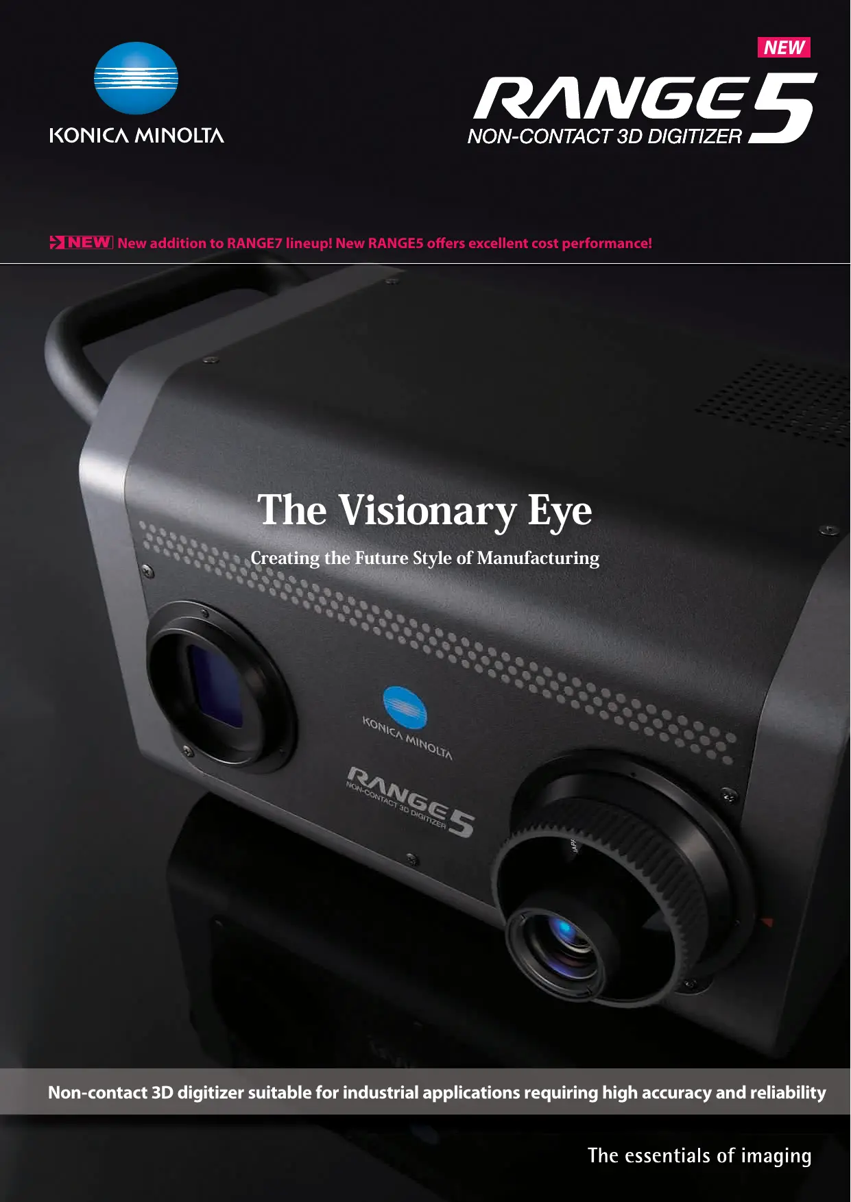
NEW New addition to RANGE7 lineup! New RANGE5 offers excellent cost performance!
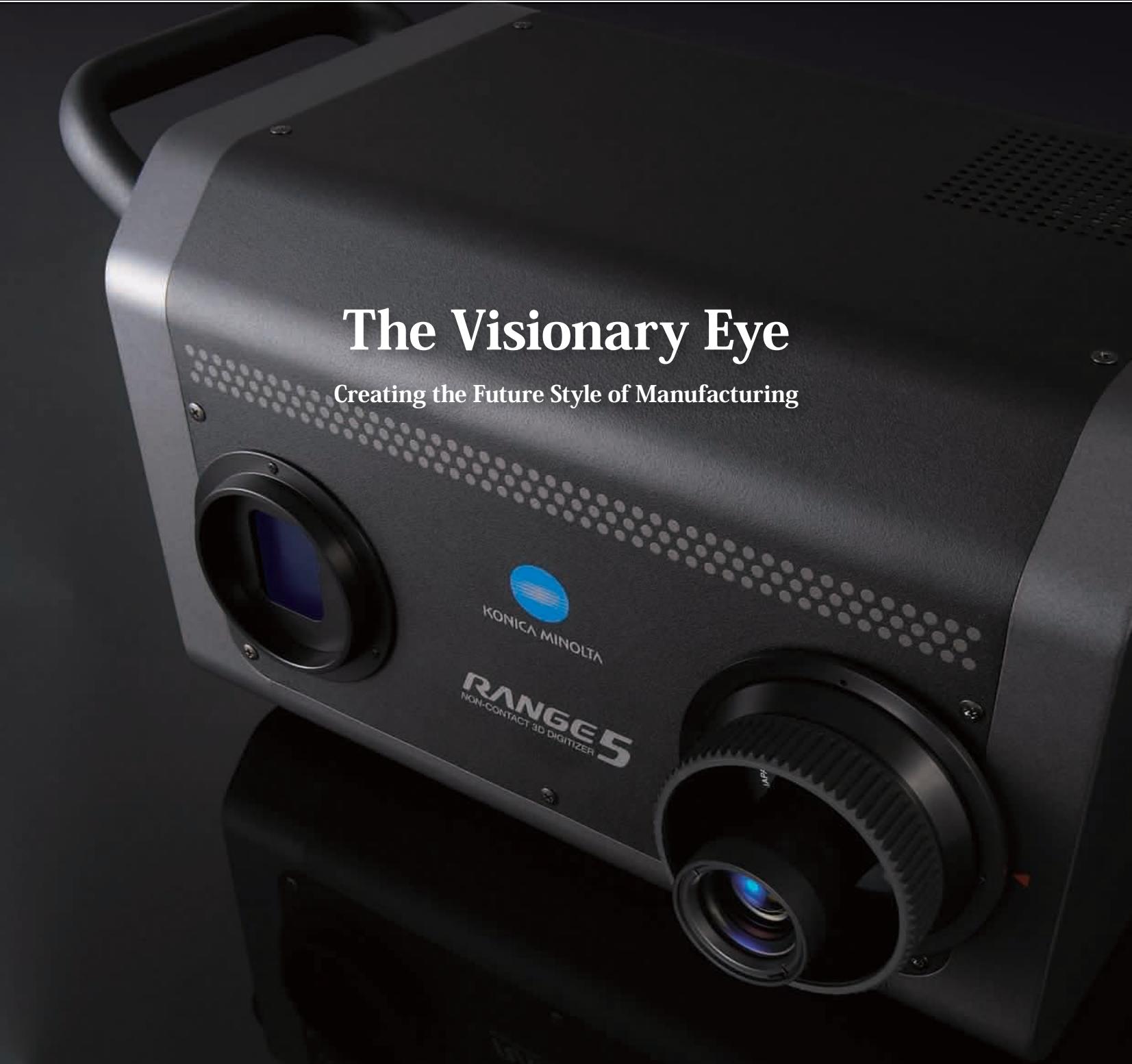
Non-contact 3D digitizer suitable for industrial applications requiring high accuracy and reliability
Do you make 2D drawings simply to check your 3D model?
How reliable is your surface profile evaluation, such as checking of distortion in a free-form surface?
Is the evaluation of wall thickness or machining stock inspection for cast parts sufficient?
Do you spend too much time correcting the dies for press parts?
Are the bosses, ribs and holes of plastic parts formed in accordance with the original design?
Is inspection totally dependent on skilled workers?
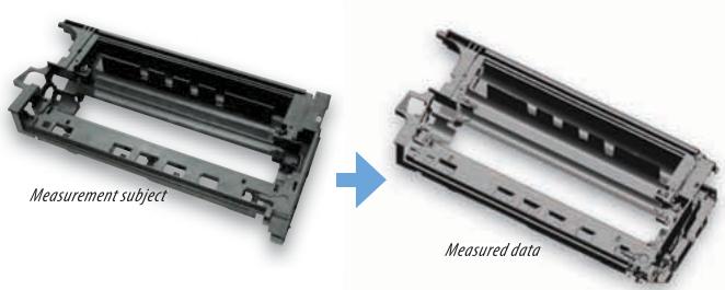
Non-contact 3D digitizer KONICA MINOLTA RANGE5 can instantaneously digitize the external profiles of various industrial parts, including press parts, machined parts, dies, prototypes, cast parts and injection molded parts, into 3D data. The digitized profile data can then be accurately reproduced on a computer screen. By comparing this data against 3D CAD data with optional application software, you can quickly output measurement reports on overall deviation, cross-sectional deviation, wall thickness distribution and GD&T (Geometric Dimensioning and Tolerance). This allows increased speed and improved quality in the manufacturing process.
In addition to measurement for inspection and quality control, KONICA MINOLTA RANGES offers various applications including:
- Reverse engineering
Rapid prototyping - Creation of machining data
- Digital mockup
KONICA MINOLTA RANGE5 opens up the future possibilities of non-contact 3D measurement by adding the elements of increased reliability, improved operability and easier transportability to Konica Minolta's accumulated optical technologies and auto-focus function.
Principal applications and measurement targets
Quality inspection (confirmation and verification of whether parts are manufactured to specifications) and reverse engineering (quantification of quality and capability of parts, etc.) from development to prototyping phases
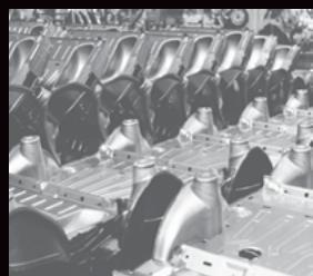
- Cast and other formed materials
- Pressed parts
- Injection molded parts
- Various machined parts
KONICA MINOLTA RANGES will change the process of manufacturing.
Problems can be solved by using KONICA MINOLTA RANGE5 and 3D CAD data, without the need for 2D drawings.
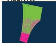
The direct comparison of 3D scan data against 3D CAD data provides visual and quantitative evaluation of surface distortion and cross-sections of part exteriors, even those with multiple free-form surfaces. By doing this, you can confirm and verify whether parts are manufactured to the design.
1 Contour evaluation
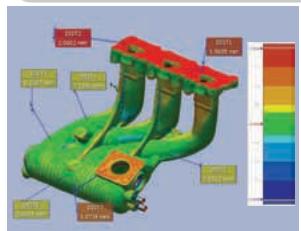
* Screen shot examples from optional application software.
^② Cross-section inspection
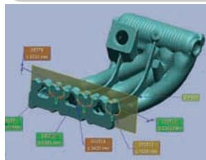
3 Dimension inspection (GD&T)
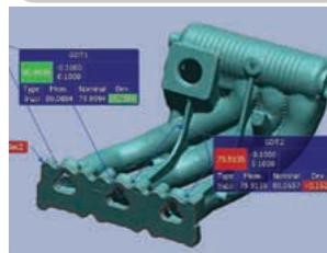
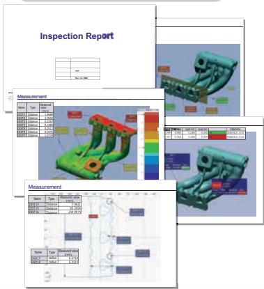
Report output
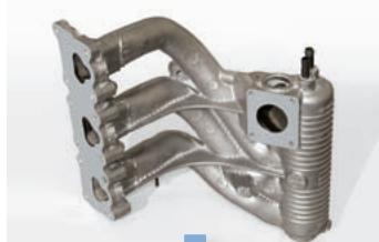
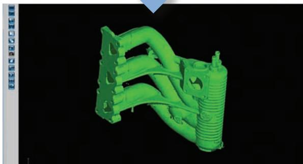
Solution 1
Cast parts can be visualized and quantified for the evaluation of wall thickness distribution, enabling inspection for excessively thin walls and lack of machining stock. Early feedback of the results to the design and production processes reduces losses in later processes.
Solution 2
By visualizing the spring-back which occurs during forming trials in press die making, the location and amount of distortion can be pinpointed precisely, leading to improved accuracy of die correction and reduced correction cycles.
Solution 3
By creating 3D CAD data of the dimensions and tolerances for inspection points such as the positions of bosses, ribs and holes of plastic products in advance, you can automatically create dimension inspection reports on GD&T analysis, etc., resulting in the development of a routine and speeding up the inspection process.

KONICA MINOLTA RANGE5 is designed to provide high operability and reliability. It is a user-friendly 3D digitizer that provides easy operation with intuitive GUIs, minimization of erroneous measurements, and always offers high-quality 3D data regardless of the target shape or surface conditions.

Innovative performance offered by a next-generation 3D digitizer
Full of various types of know-how to enable high-quality 3D data to be obtained quickly and easily.
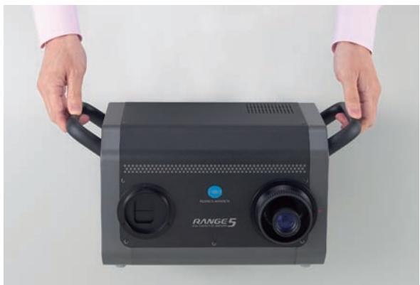
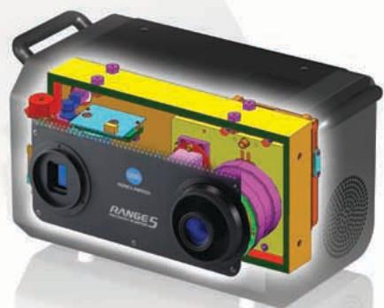
01 Easy-to-carry digitizer with integrated camera and controller
The KONICA MINOLTA RANGES is a new 3D digitizer series full of 3D digitizing know-how accumulated from Kona Minolta's over 10 years of experience. The compact and lightweight design integrates the camera and controller in a single body weighing only approximately 6.7kg , providing high mobility on measurement sites.
02 Various focusing functions for quick capturing of clear 3D data
The auto-focus (AF) function implements further advances that only Konica Minolta could provide, to offer a multi-focus mode which automatically shifts the focus position in two steps to obtain more accurate and sharper 3D measurement data. This is especially effective for measurement of deep objects. The adjustment of distance and angle of view is also easy by using the point AF function which adjusts the focus to the point specified by the user and the Field of View (FOV) indicator which shows the current measurement area.
The FOV indicator shows the current measurement area.
03 The 3D preview function reduces erroneous measurements
The 3D preview function allows users to predict measurement results quickly. With a pre-scan of only 0.4 seconds, users can check for measurement area depth, dead angles, scan problems due to surface conditions, etc. beforehand to greatly reduce erroneous measurements.
Check the focus on the monitor screen.
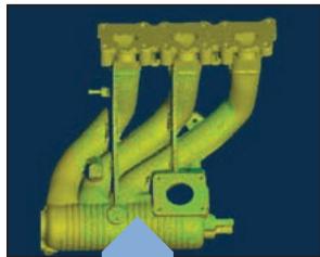
Measurement results
Preview is displayed in 0.4 seconds.
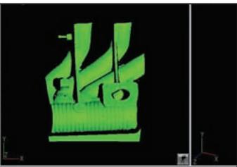
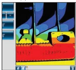
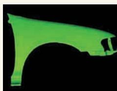
04 Excellent ability to measure glossy surfaces, surpassing normal assumptions regarding optical 3D digitizers
The new sensor and original measurement algorithm ensure a wider dynamic range. Even glossy objects, such as metallic surfaces, can be measured reliably.
Measurement of the machined surface of a cast part
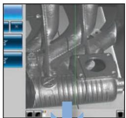
The newly developed software RANGE VIEWER allows comfortable scanning operations.
The software, designed specifically for KONICA MINOLTA RANGE Series, makes the process from scanning to data integration quick and easy.
01 Capable of measuring dark surfaces without using spray or a special darkroom.
The RANGE5 is equipped with a new Dark Surface Mode measurement function ^+1 developed utilizing our original data-processing technology that enables measurements of dark objects (with reflectances as low as 2.5% ^{*2}). Since spraying before measurement is not required, measurement inaccuracies caused by uneven spray layer thickness are eliminated, and since spray and cleaning liquids are not used, environmental load is also reduced. Plus, measurements can be taken in a normal office environment ^+3 , so there is no need to invest in a special darkroom.
1 Although it has been greatly improved compare to our previous instruments, there is no guarantee that the RANGES can measure all dark surfaces or metallic gloss surfaces without spraying. Whether or not treatment of the surface prior to measurement is necessary depends on actual use conditions.
2 Reflectance at 660nm excluding specular reflectance. Based on Konica Minolta standard measurement conditions.
*3 500 lx or less
Measurement example using Dark Surface Mode measurement function
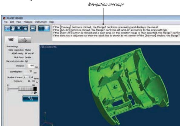
02 User-friendly software with navigation messages
"RANGE VIEWER" is newly developed 3D data processing software included as standard. It provides various editing functions from scanning control of the instrument to alignment of measured data and data merging. Easy-to-see icons and a flexible GUI allow scanning and data editing to be done seamlessly. The navigation messages which show instructions or the next step allow beginners to easily and quickly learn operation. RANGE VIEWER supports 64-bit editions of Windows®, enabling large volumes of data to be processed. It also allows quick data transfer to optional application software via IPC (Inter Process Communication) without the need to save files.
- For detailed specifications, refer to the Operating Environment of RANGE VIEWER in this catalog.
03 Easy operation and high processing ability for reduced total operation time
The total operation time from the setting of distance and angle of view, through scanning, to data integration is about 35 minutes* to measure Konica Minolta's standard sample from 30 directions. High operability and a processing ability of approximately
1 minute/cycle on average has been achieved.
* Measurement using markers (optional accessory). Other conditions are according to Konica Minolta Sensing standards.
Measurement procedure with KONICA MINOLTA RANGE5 (measurement using markers)

① Attach markers so that five to ten markers are displayed on the monitor screen during measurement.
② Perform measurement and check that the markers are displayed on the monitor screen.
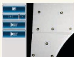
③ Position is aligned according to the automatic recognition of three or more matching markers in overlapped images during measurements.
④ Results of the measurement of the entire target are obtained by repeating steps ② and ③
Toward new horizons for optical 3D digitizers
The KONICA MINOLTA RANGE5 boasts high accuracy and reliability. Points Konica Minolta Sensing cannot compromise as a manufacturer of measuring instruments.
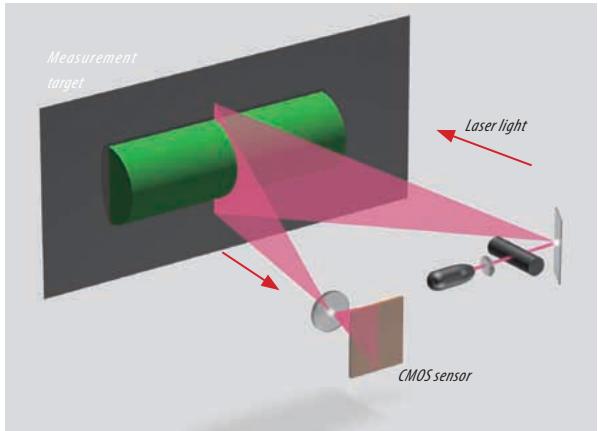
01 Stable scanning with light sectioning method
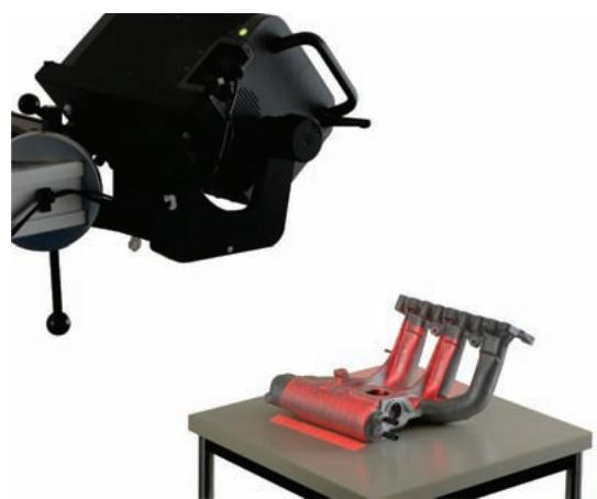
KONICA MINOLTA RANGE5 employs triangulation by the light sectioning method, using a Class-2 semiconductor laser to sweep the target with laser light. In as little as approximately 2 seconds, a target is scanned with laser light that has passed through a slit, and the reflected light is received by the 1.31-megapixel CMOS sensor that provides high-resolution information.
The information is then converted into 3D data using the data for distance to the target calculated based on the triangulation principle. One scan can obtain up to approximately 1,310,000 points (1,280 × 1,024 points) of 3D coordinate data.
02 High reliability with minimized influence from environment conditions
The KONICA MINOLTA RANGES5 has adopted a new optical system which adjusts focus based on the signal from the image pickup device. It also has an integrated inner base-plate made of CFRP (carbon fiber reinforced plastic). As a result, the KONICA MINOLTA RANGES5 has achieved a lightweight body, great rigidity and high driving accuracy. At the time of measurement, the KONICA MINOLTA RANGES5 provides high reliability when operating in various environments by minimizing the influence of instrument tilt, temperature changes, etc.
03 High measurement accuracy based on strict inspection standards
The KONICA MINOLTA RANGE5 has achieved high measurement accuracy1 of ± 80~ m^2 in accuracy evaluation using ball bars3 according to the guidelines in "VDI/VDE 26344 Part 2". The testing method utilizing ball bars is planned to be included in a Japanese Industrial Standards proposal related to the testing of optical non-contact coordinate measuring instruments.
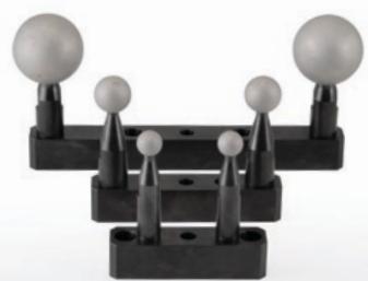
Ball bars
(For RANGE7, 5)
Konica Minolta performs testing based on "VDI/VDE 2634 Part 2" using ball bars calibrated by the National Institute of Advanced Industrial Science and Technology of Japan for all KONICA MINOLTA RANGES5 units. We build confidence by clearly indicating the product accuracy and by conducting strict testing for each unit before shipment.
1 Accuracy: Measuring instrument accuracy expressed as error limits under the defined conditions.
2 Measured at a distance of 450 ~mm and ambient temperature of 20 ± 1^ C . Other conditions are according to Konica Minolta Sensing standards.
3 Ball bar: Equipment for evaluation of accuracy, consisting of a bar that has balls attached at both ends.
4 VDI/VDE 2634: Optical measurement system testing guidelines issued by Germany in 2002.
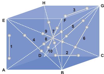
Measurement of a ball bar at 10 positions inside a defined space as pre-shipment inspection (conceptual image)
04 On-site calibration for maintaining high reliability
A compact calibration chart that can be set up on a table is supplied as standard. When calibration is required due to changes in ambient temperature, all you have to do is to scan the calibration chart according to the software guidance.
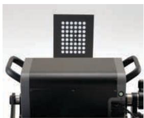
Compact calibration chart (standard accessory)
This will ensure measurements with the same accuracy as the time of shipment from the factory.
Increased mobility and operability of the compact, lightweight KONICA MINOLTA RANGES
Various accessories specifically designed for KONICA MINOLTA RANGE Series offer flexible system configuration according to the application and operating environment.

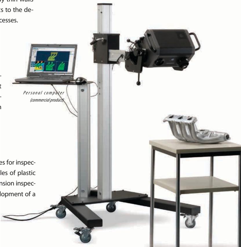
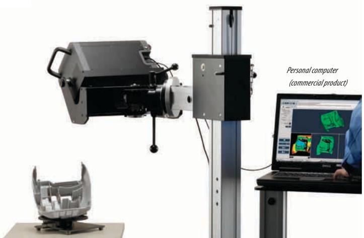
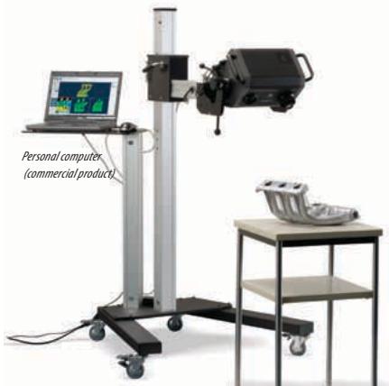
Measuring Stand Set with laptop shelf
(optional accessory)
The optional measuring stand allows stress-free work in cases where measurement requires the KONICA MINOLTA RANGE5 to
be moved around.
Since the stand has a shelf on which a laptop PC can be placed, an all-in-one system can be built to provide high mobility within the measurement environment.

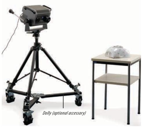
Tripod Set (optional accessory)
The tripod can also be used with a dolly (optional accessory) for easy movement.

Carrying Case (optional accessory)
The instrument, calibration chart and cables can be stored securely.
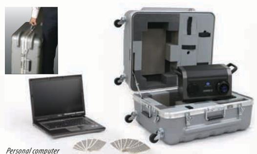
Personal computer (commercial product)

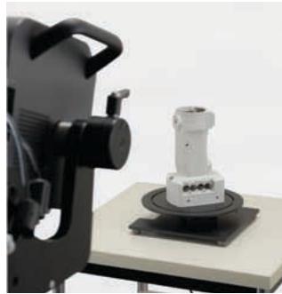
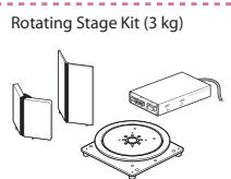
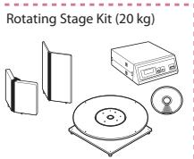
Rotating Stage Kit (3 kg/20 kg)
(optional accessory)
The rotating stage kit allows automatic positioning of a target for measuring from all sides through 360^ . Two models are available depending on the load: 3 kg and 20 kg.

Optional application software for reverse engineering, testing, etc.
To compliment the advanced features of the KONICA MINOLTA RANGE5 scanner, Konica Minolta offer a range of third-party software solutions. Together we can identify the most effective solution to meet the needs of the user to ensure they obtain maximum benefit from their investment. The software packages offered by Konica Minolta include:

magic

PolyWorks
By InnovMetric Software Inc.

RAPIDFORM
Etc
In addition the data from the KONICA MINOLTA RANGE5 can be output in many standard formats enabling data to be imported to the majority of CAD software packages.
Specifications of KONICA MINOLTA RANGES5
| Measuring method | Triangulation by light sectioning method | |||
| Light source | Semiconductor laser, Wavelength: 660 nm | |||
| Laser class | Class 2 (IEC 60825-1 Edition 2) | |||
| Number of pixels taken | 1.31 megapixels (1280 x 1024) | |||
| Measurement distance | 450 to 800 mm | |||
| Measure-ment range(mm) | Distance | 450 mm | 800 mm | |
| Direction | X × Y | 150×188 | 267×334 | |
| Z | 109 | 194 | ||
| XY direction measurement interval | 0.16 | 0.28 | ||
| Accuracy (Distance be-tween balls)*1 | ±80 μm | |||
| Precision (Z, σ)*2 | 8 μm | |||
| Auto-focus | Provided | |||
| Auto-exposure | Provided | |||
| Scan time | Approx. 2 sec. or more (1 scan) | |||
| Preview function | Approx. 0.4 sec./scan | |||
| Scanning ambient lighting condition | 500 lx or less | |||
| Output interface | USB 2.0 High Speed | |||
| Power | Included AC Adapter Input voltage: 100 to 240 VAC (50/60 Hz), Rat- ing: 1.4 A (at 100 VAC input) | |||
| Dimensions | 295 (W) x 190 (H) x 200 (D) mm (Excluding grips and lens) | |||
| Weight | Approx. 6.7 kg | |||
| Operating temperature/humidity range | 10 to 40°C; Relative humidity 65% or less (no condensation) | |||
| Storage temperature/humidity range | -10 to 50°C; Relative humidity 85% or less (at 35°C, no condensation) | |||
1 When measuring the distance between balls for a ball bar (two balls) as defined in VDI/VDE 2634-2 under Konica Minolta Sensing measurement conditions.
Konica Minolta Sensing measurement conditions: Temperature: 20 ± 1^ C , Measurement distance: 450 ~mm ; Warm-up: 20 ~min ; Software used: Konica Minolta processing software; After calibration of the instrument; Measurement target: Konica Minolta standard target (2 balls); Arrangement of measurement target: Konica Minolta standard arrangement (10 positions inside measurement space); Uncertainty of standard target not included.
2 Measurement conditions: Temperature: 20 ± 1^ C ,Measurement distance: 450 mm ; Warm-up: 20 min ; Measurement target: Konica Minolta standard planar chart; Software used: Konica Minolta processing software; 1 σ value
*3 Using Konica Minolta processing software
Specifications of 3D Data Processing Software RANGE VIEWER
Major Functions>
| Readable data formats | Readable data formats Konica Minolta proprietary formats: .rgv (Single-scan data group), .rvm (more than one piece of data) |
| Data output | STL (binary), ASCII point group Konica Minolta proprietary formats: .rgv, .rvm, .rmk |
| Measurement functions | Monitor image, Preview, AF/AE, Measurement Control of rotating stage (Konica Minolta optional accessory) |
| Editing functions | Data alignment, Data merging (integration), Point group deletion |
| Drawing | Point group shading |
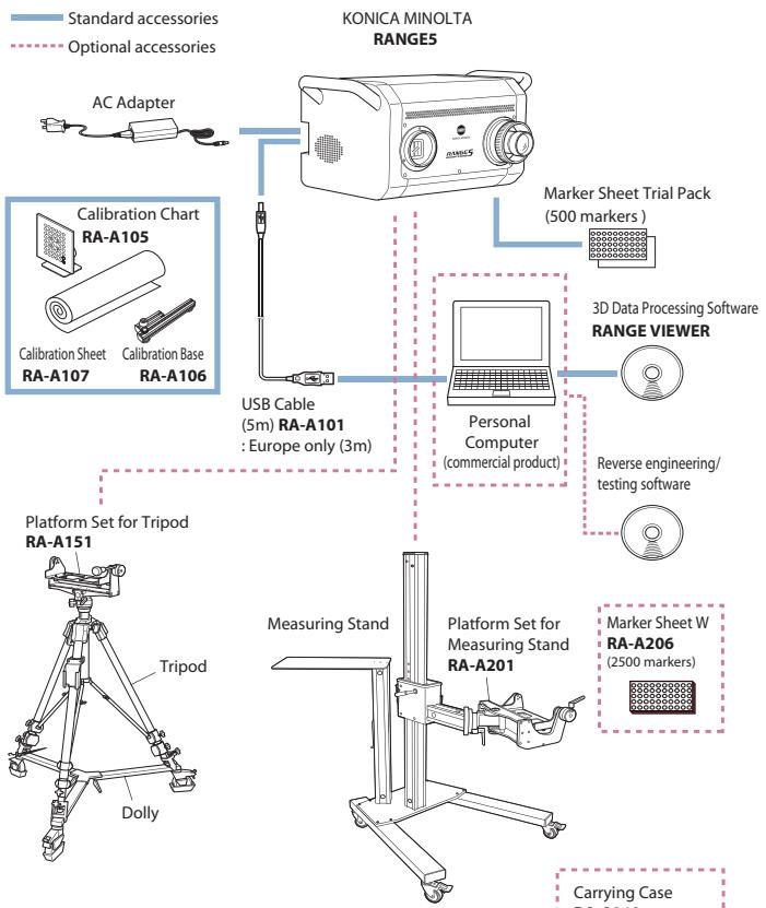
System configuration
Carrying Case RA-A213

- Specifications and appearance shown herein subject to change without notice.
- Company names and product names used herein are trademarks or registered trademarks of their respective companies.
- Screens shown are for illustration purpose only.
| OS | Windows® Vista Business SP1(64bit), Windows® XP Professional x64 Edition SP2 (64bit) |
| CPU | Core2 Duo, Xeon or higher |
| RAM | 4 GB or more |
| Display | Graphics display capability of 1280 x 1024 or more |
| Graphics board | OpenGL compatible board (Konica Minolta verified compatible board recommended) |
| Interface | USB 2.0 port |
SAFETY PRECAUTIONS
Read all safety and operating instructions before operating the KONICA MINOLTA RANGE5.
- Use only a power source of the specified rating. Improper connection may cause a fire or electric shock.
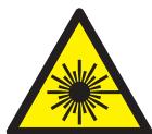
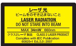
- Do not stare into the laser beam. (MAX. 34mW 660nm, CLASS 2 (IEC) LASER PRODUCT)


Registration No.:YKA 0937154
Registration date: March 3, 1995
Registration No.: JQA-E-80027
Registration date: March 12, 1997
| KONICA MINOLTA SENSING, INC. | Osaka, Japan | EMail : 3dsales@konicaminolta.jp | Web : http://konicaminolta.com/instruments | |
| Konica Minolta Sensing Americas, Inc. | New Jersey , U.S.A. | Phone: 888-473-2656 (in USA), 201-236-4300 (outside USA) Fax: 201-785-2482 E-mail : vivid3d@se.konicaminolta.us | Web : http://se.konicaminolta.us/3d | |
| Konica Minolta Sensing Europe B.V. | German Office | München, Germany E-mail : info.germany@seu.konicaminolta.eu | Phone: +49(0)89 4357 156 0 Web : http://www.konicaminolta.eu | Fax: +49(0)89 4357 156 99 |
| French Office | Roissy CDG, France E-mail : info.france@seu.konicaminolta.eu | Phone: +33(0)1 493-82519 Web : http://www.konicaminolta.eu | Fax: +33(0)1 493-84771 | |
| UK Office | Milton Keynes, United Kingdom E-mail : info.uk@seu.konicaminolta.eu | Phone: +44(0)1908 540-622 Web : http://www.konicaminolta.eu | Fax: +44(0)1908 540-629 | |
| Italian Office | Milan, Italy E-mail :info.italy@seu.konicaminolta.eu | Phone: +39 02 39011.425 Web : http://www.konicaminolta.eu | Fax: +39 02 39011.223 | |
| Polish Office | Wroclaw, Poland E-mail : info.poland@seu.konicaminolta.eu | Phone: +48(0)71 33050-01 Web : http://www.konicaminolta.eu | Fax: +48(0)71 734 52 10 | |
| Konica Minolta (CHINA) Investment Ltd. | SE Sales Division | Shanghai, China Singapore | Phone: +86-021-5489 0202 | Fax: +86-021-5489 0005 |
| Konica Minolta Sensing Singapore Pte Ltd. | Phone: +65 6563-5533 | Fax: +65 6560-9721 | ||
- Principal applications and measurement targets
- KONICA MINOLTA RANGES will change the process of manufacturing.
- Contour evaluation
- ② Cross-section inspection
- Dimension inspection (GD&T)
- Report output
- Solution 1
- Solution 2
- Solution 3
- Innovative performance offered by a next-generation 3D digitizer
- Easy-to-carry digitizer with integrated camera and controller
- Various focusing functions for quick capturing of clear 3D data
- The 3D preview function reduces erroneous measurements
- Excellent ability to measure glossy surfaces, surpassing normal assumptions regarding optical 3D digitizers
- The newly developed software RANGE VIEWER allows comfortable scanning operations.
- Capable of measuring dark surfaces without using spray or a special darkroom.
- User-friendly software with navigation messages
- Easy operation and high processing ability for reduced total operation time
- Measurement procedure with KONICA MINOLTA RANGE5 (measurement using markers)
- Toward new horizons for optical 3D digitizers
- Stable scanning with light sectioning method
- High reliability with minimized influence from environment conditions
- High measurement accuracy based on strict inspection standards
- On-site calibration for maintaining high reliability
- Increased mobility and operability of the compact, lightweight KONICA MINOLTA RANGES
- Measuring Stand Set with laptop shelf
- Rotating Stage Kit (3 kg/20 kg)
- Optional application software for reverse engineering, testing, etc.
- SAFETY PRECAUTIONS
Brand : MINOLTA
Model : RANGE 5
Category : Camera