
DDC 707 DF - Cooker DELONGHI - Free user manual and instructions
Find the device manual for free DDC 707 DF DELONGHI in PDF.


| Brand | DeLonghi |
| Model | DDC 707 DF |
| Product type | Freestanding dual-fuel cooker |
| Width | 70 cm |
| Height | 85 cm |
| Depth | 60 cm |
| Hob type | Gas hob with 4 burners |
| Hob features | Triple-ring wok burner, automatic electric ignition |
| Oven type | Electric oven with fan-assisted convection |
| Oven functions | Conventional, fan, grill, fan-assisted grill, defrost |
| Oven capacity | 71 litres |
| Power supply | 230 V / 50 Hz electrical; natural gas or LPG |
| Oven power | 2200 W |
| Safety features | Flame failure device on all gas burners, cool-touch door |
| Control panel | Ergonomically placed rotary knobs, clear markings |
| Cleaning | Removable inner glass door, enamel-coated oven cavity |
| Maintenance | Accessible burner caps and pan supports, replaceable oven bulb |
| Spare parts | Available from DeLonghi authorised service centres |
| Repairability | Modular design with easily replaceable heating elements and thermostats |
| Weight | 52 kg |
| Colour | Stainless steel / silver finish |
Frequently Asked Questions - DDC 707 DF DELONGHI
User questions about DDC 707 DF DELONGHI
0 question about this device. Answer the ones you know or ask your own.
Ask a new question about this device
Download the instructions for your Cooker in PDF format for free! Find your manual DDC 707 DF - DELONGHI and take your electronic device back in hand. On this page are published all the documents necessary for the use of your device. DDC 707 DF by DELONGHI.
USER MANUAL DDC 707 DF DELONGHI
Gas installation 15 - 20
Electrical section 21 - 22
Advice For The Users....24
Cooking Hob 25
Control Panel 26
Electronic programmer....27 - 32
Use of hob burners....33 - 35
Bottom main oven....36 - 37
Cooking Advice 38
Top conventional electric oven 39 - 41
Oven Temperature....42 - 43
Cleaning & maintenance....44 - 49
Guarantee & After Sales Service 50
Dear Customer,
Thank you for purchasing the DeLonghi DDC 707 DF dual fuel cooker.
The safety precautions and recommendations listed below are for your own safety and that of others. They will also provide a means by which to make full use of the features offered by your appliance.
Please retain this booklet for future reference.
This appliance must be used only for the task it has explicitly been designed for, that is for cooking foodstuffs. Any other form of usage is to be considered as inappropriate and therefore potentially dangerous.
The manufacturer declines all responsibility in the event of damage caused by improper, incorrect or illogical use of the appliance.
IMPORTANT INFORMATION FOR CORRECT DISPOSAL OF THE PRODUCT IN ACCORDANCE WITH EC DIRECTIVE 2012/19/EC.
At the end of its working life, the product must not be disposed of as urban waste. It must be taken to a special local authority differentiated waste collection centre or to a dealer providing this service.
Disposing of a household appliance separately avoids possible negative consequences for the environment and health deriving from inappropriate disposal and enables the constituent materials to be recovered to obtain significant savings in energy and resources. As a reminder of the need to dispose of household appliances separately, the product is marked with a crossed-out wheeled dustbin.

DECLARATION OF CE CONFORMITY
- This appliance has been designed to be used only for cooking. Any other use (such as heating a room) is improper and dangerous.
-
This appliance has been designed, constructed, and marketed in compliance with:
-
Safety requirements of the "Gas" Regulation (EU) 2016/426;
- Safety requirements of the "Low voltage" Directive 2014/35/EU;
- Safety requirements of the "EMC" Directive 2014/30/EU;
- Requirements of EU Directive 93/68/EEC;
- Requirements of EU Directive 2011/65/EU.

IMPORTANT: This appliance is designed and manufactured solely for the cooking of domestic (household) food and is not suitable for any non domestic application and therefore should not be used in a commercial environment.
The appliance guarantee will be void if the appliance is used within a non domestic environment i.e. a semi commercial, commercial or communal environment.
Read the instructions carefully before installing and using the appliance.
- This appliance has been designed and manufactured in compliance with the applicable standards for the household cooking products and it fulfills all the safety requirements shown in this manual, including those for surface temperatures.
Some people with sensitive skin may have a more pronounced temperature perception with some components although these parts are within the limits allowed by the norms.
The complete safety of the appliance also depends on the correct use, we therefore recommend to always pay a extreme attention while using the product, especially in the presence of children.
- After having unpacked the appliance, check to ensure that it is not damaged and that the oven door closes correctly.
In case of doubt, do not use it and consult your supplier or a professionally qualified technician. - Packing elements (i.e. plastic bags, polystyrene foam, nails, packing straps, etc.) should not be left around within easy reach of children, as these may cause serious injuries.
- Some appliances are supplied with a protective film on steel and aluminium parts. This film must be removed before using the appliance.
- IMPORTANT: The use of suitable protective clothing/gloves is recommended when handling or cleaning this appliance.
- Do not attempt to modify the technical characteristics of the appliance as this may become dangerous to use. The
manufacturer declines all responsibility for any inconvenience resulting from the inobservance of this condition.
- CAUTION: this appliance must only be installed in a permanently ventilated room in compliance with the applicable regulations.
- Do not operate your appliance by means of an external timer or separate remote-control system.
- Do not carry out cleaning or maintenance operations on the appliance without having previously disconnected it from the electric power supply.
- WARNING: Ensure that the appliance is switched off before replacing the oven lamp to avoid the possibility of electric shock.
- Do not use a steam cleaner because the moisture can get into the appliance therefore making it unsafe.
- Do not touch the appliance with wet or damp hands (or feet).
- Do not use the appliance whilst in bare feet.
- If you should decide not to use this appliance any longer (or decide to substitute another model), before disposing of it, it is recommended that it be made inoperative in an appropriate manner in accordance to health and environmental protection regulations, ensuring in particular that all potentially hazardous parts be made harmless, especially in relation to children who could play with unused appliances.
- The various components of the appliance are recyclable. Dispose of them in accordance with the regulations in force in your country. If the appliance is to be scrapped, remove the power cord.
• After use, ensure that the knobs are in the off position.
- Children less than 8 years of age shall be kept away unless continuously supervised.
- This appliance can be used by children aged from 8 years and above and persons with reduced physical, sensory or mental capabilities or lack of experience and knowledge if they have been given supervision or instruction concerning use of the appliance in a safe way and understand the hazards involved. Children shall not play with the appliance. Cleaning and user maintenance shall not be made by children without supervision.
- The manufacturer declines all liability for injury to persons or damage to property caused by incorrect or improper use of the appliance.
-
WARNING: During use the appliance and its accessible parts become hot; they remain hot for some time after use.
-
Care should be taken to avoid touching heating elements (on the hob and inside the oven).
- The door is hot, use the handle.
-
To avoid burns and scalds, young children should be kept away.
-
Make sure that electrical cables connecting other appliances in the proximity of the cooker cannot come into contact with the hob or become entrapped in the oven door.
- WARNING: Unattended cooking on a hob with fat or oil can be dangerous and may result in fire. NEVER try to extinguish a fire with water, but switch off the appliance and then cover flame e.g. with a lid or a fire blanket.
- WARNING: Danger of fire: do not store items on the cooking surfaces.
- WARNING: When correctly installed, your product meets all safety requirements laid down for this type of product category. However special care should be taken around the rear or the underneath of the appliance as these areas are not designed or intended to be touched and may contain sharp or rough edges, that may cause injury.
- FIRST USE OF THE OVEN - it is advised to follow these instructions:
– Furnish the interior of the oven as described in the chapter "CLEANING AND MAINTENANCE".
- Switch on the empty oven on max to eliminate grease from the heating elements.
- Disconnect the appliance from the electrical power supply, let the oven cool down and clean the interior of the oven with a cloth soaked in water and neutral detergent; then dry carefully.
- CAUTION: Do not use harsh abrasive cleaners or sharp metal scrapers to clean the oven door glass since they can scratch the surface, which may result in shattering of the glass.
- Do not line the oven walls or base with aluminium foil. Do not place baking trays or the drip tray on the base of the oven chamber.
- Do not cover the hob with aluminium foils.
- FIRE RISK! Do not store flammable material in the oven or in the storage compartment.
- Always use oven gloves when removing the shelves and food trays from the oven whilst hot.
- Do not hang towels, dishcloths or other items on the appliance or its handle – as this could be a fire hazard.
- Clean the oven regularly and do not allow fat or oils to build up in the oven base or tray. Remove spillages as soon as they occur.
- Do not stand on the cooker or on the open oven door.
- Always stand back from the appliance when opening the oven door to allow steam and hot air to escape before removing the food.
- SAFE FOOD HANDLING: Leave food in the oven for as short a time as possible before and after cooking. This is to avoid contamination by organisms which may cause food poisoning. Take particular care during warmer weather.
- WARNING: Take care NOT to lift the cooker by the door handle.
- CAUTION: The cooking process has to be supervised. A short term cooking process has to be supervised continuously.
- The appliance must not be installed behind a decorative door in order to avoid overheating.
- The oven accessories (e.g. oven wire rack) must be fitted correctly as indicated at page 47.
- IMPORTANT NOTE: The oven shelves (for some products one shelf only is provided) have not been designed to place the food directly on the shelf itself. When cooking, always place the food in special containers or use specific materials suitable for the food contact.
- If the power supply cable is damaged, it must be replaced only by an authorized service agent in order to avoid a hazard.
- If the appliance is not fitted with a supply cord and a plug, or with other means for disconnection from the supply mains having a contact separation in all poles that provide full disconnection
under overvoltage category III conditions, means for disconnection must be incorporated in the fixed wiring in accordance with the wiring rules.
- WARNING: The appliance and its accessible parts become hot during use.
Care should be taken to avoid touching heating elements.
Children less than 8 years of age shall be kept away unless continuously supervised.
- WARNING: Use only hob guards designed by the manufacturer of the cooking appliance or indicated by the manufacturer of the appliance in the instructions for use as suitable or hob guards incorporated in the appliance. The use of inappropriate guards can cause accidents.
ENERGY LABELLING/ECODESIGN
- Commission delegated regulation (EU) No 65/2014 (supplementing Directive 2010/30/EU of the European Parliament and of the Council).
- Commission regulation (EU) No 66/2014 (implementing Directive 2009/125/EC of the European Parliament and of the Council).
Reference to the measurement and calculation methods used to establish compliance with the above requirements:
• Standard EN 60350-1 (electric ovens).
- Standard EN30-2-1 (hobs: gas fired burners).
USE OF THE APPLIANCE, ENERGY SAVING TIPS
OVEN
- Check the oven door always closes properly and the door gasket is clean and in order. During use, open the oven door only when strictly necessary to avoid heat losses (for some functions it may be necessary to use the oven with the door half-closed, check the oven operating instructions).
- Turn off the oven 5-10 minutes before the end of the theoretical cooking time to recuperate the stored heat.
- We recommend using oven proof dishes and adjusting the oven temperature during cooking if necessary.
HOB
GAS FIRED BURNERS
- It is important that the diameter of the pot be suitable to the size of the burner so as not to compromise the high output of the burners and therefore energy waste. A small pot on a large burner does not give you a boiling point in a shorter amount of time since the capacity of heat absorption of a liquid mass depends on the volume and the surface of the pot.
- Avoid keeping a burner on without something on it (without pot).
Advice for the installer
IMPORTANT
- The appliance is designed and approved for domestic use only and should not be installed in a commercial, semi commercial or communal environment, in Motorhomes, Caravans (except Static/Park Homes), or any boat or vessel used on the sea, estuary, lakes or inland waterways.
Your product will not be guaranteed if installed in any of the above environments and could affect any third party or public liability insurances you may have.
The appliance may be installed in a kitchen, kitchen/diner or a bed sitting room, but not in a room or space containing a bath or a shower without first consulting current regulations.
The appliance must not be installed in a bed-sitting room of less than 20m3 .
- Cooker installation must only be carried out by a SUITABLY QUALIFIED AND REGISTERED TECHNICIAN and in compliance with local safety standards.
Failure to observe this rule will invalidate the warranty.
- Incorrect installation, for which the manufacturer accepts no responsibility, may cause personal injury of damage.
- This appliance shall only be serviced by authorized personnel.
- Always disconnect the appliance from the power supply before carrying out any maintenance operations or repairs.
• Take care NOT to lift the oven by the door handle/s. - Some appliances are supplied with a protective film on steel and aluminium parts. This film must be removed before using the cooker.
- Important: The use of suitable protective clothing/gloves is recommended when handling or installing this appliance.
- The walls of the units must not be higher than work top and must be capable of resisting temperatures of 70 °C above room temperature.
- We would point out that the adhesive which bonds the plastic laminate to the furniture must withstand temperatures not less than 150°C to avoid delamination.
- Do not install the appliance near inflammable materials (e.g. curtains).
WARNING
When correctly installed, your product meets all safety requirements laid down for this type of product category.
However special care should be taken around the rear or the underneath of the appliance as these areas are not designed to be touched and may contain sharp or rough edges, that may cause injury.
1 - INSTALLATION
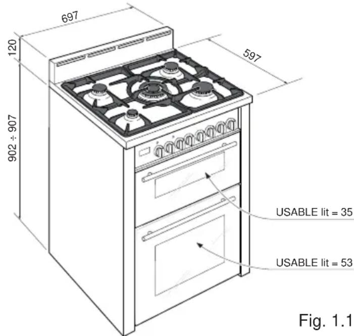
This cooker has class "2/1" overheating protection so that it can be installed next to a cabinet.
If the cooker is installed adjacent to furniture which is higher than the gas hob cooktop, a gap of at least 200 mm must be left between the side of the cooker and the furniture.
The walls and kitchen furniture surrounding the appliance must be made of non-flammable material. The veneered synthetical material and the glue used must be resistant to a temperature of 150 °C in order to avoid ungluing or deformations. It is recommended that a 10 mm gap to each side is made if the adjacent kitchen furniture is made of a plastic laminate wrap.
Curtains must not be fitted immediately behind appliance or within 500 mm of the sides.
It is essential that the cooker is positioned as stated below.
We do not recommend the cooker is located on a plinth. If this is unavoidable, it will be necessary to provide safety measures to prevent the appliance falling off.
The cooker must be installed by a suitably qualified technician and in compliance with local safety standards.

Before installing the cooker level the appliance by screwing or unscrewing the four adjustable feet fitted below.
WARNING!
For safety reasons unscrew the feet (from screwed in position) to the maximum extent of 5 mm (fig. 1.3).

BACKGUARD
- Remove the screws "A" from the rear of the cooktop.
• Assemble the backguard as shown in fig 1.4 and fix it by screwing the no.3 screws "A".
It is mandatory to install the backguard.

MOVING THE COOKER
WARNING: When raising cooker to upright position always ensure two people carry out this manoeuvre to prevent damage to the adjustable feet (fig. 1.5).

WARNING
Be careful: do not lift the cooker by the door handle when raising to the upright position (fig. 1.6).
WARNING
When moving cooker to its final position DO NOT DRAG (fig. 1.7). Lift feet clear of floor (fig. 1.5).

Fig. 1.7

Anti-Tilt Bracket
Important!
To restrain the appliance and prevent it tipping accidentally, the anti-tilt bracket supplied must be fitted according to the instructions below.
To fit the anti-tilt bracket:
-
After you have located where the cooker is to be positioned, mark on the wall and on the floor the place where the four screws of the anti-tilt bracket have to be fitted. Please follow the indications given in fig. 1.8.
-
Drill four 8 mm diameter holes for the fixing screws (two in the wall and two in the floor-see fig. 1.8) and insert the plastic plugs supplied.
Important!
Before drilling the holes, check that you will not damage any pipes or electrical wires.
-
Attach the anti-tilt bracket to the floor and rear wall using the four screws supplied, as shown in fig. 1.8.
-
After attaching the anti-tilt bracket securely, slide the cooker into place. Ensure that the rear left foot slides under the bracket, as shown in fig. 1.8.
Attention!
When sliding the cooker into place pay special not to trap the power supply cable in the stability bracket.
Pay special attention to the gas connection hose.

Provision for Ventilation
- The appliance should be installed into a room or space with an air supply in accordance with BS 5440-2: 2000.
- For rooms with a volume of less than 5 m 3 - permanent ventilation of 100 cm 2 free area will be required.
- For rooms with a volume of between 5 m 3 and 10 m 3 a permanent ventilation of 50 cm 2 free area will be required unless the room has a door which opens directly to the outside air in which case no permanent ventilation is required.
- For rooms with a volume greater than 10 m 3 - no permanent ventilation is required.
Note: Regardless of room size, all rooms containing the appliance must have direct access to the outside air via a window that can be opened or equivalent.
- Where there are other fuel burning appliances in the same room, BS 5440-2:2000 should be consulted to determine the correct amount of free area ventilation requirements.
- The above requirements allow also for use of a gas oven and grill but if there are other gas burning appliances in the same room, consult a qualified engineer.
This appliance is supplied for use on NATURAL GAS or LPG (check the gas regulation label attached on the appliance).
- Appliances supplied for use on NATURAL GAS are adjusted for this gas only and cannot be used on any other gas (LPG) without modification. The appliances are manufactured for conversion to LPG.
- Appliances supplied for use on LPG are adjusted for this gas only and cannot be used on any other gas (NATURAL GAS) without modification. The appliances are manufactured for conversion to NATURAL GAS.
If the NATURAL GAS/LPG conversion kit is not supplied with the appliance this kit can be purchased by contacting the After-Sales Service.
INSTALLATION & SERVICE REGULATIONS (UNITED KINGDOM)
It is a legal requirement that all gas appliances are Installed & Serviced by a competent person in accordance with the current editions of the following Standards & Regulations or those regulations appropriate to the geographical region in which they are to be installed:
• Gas Safety (Installation & Use) Regulations
• Building Regulations
• British/European Standards
• Regulations for Electrical Installation
Installation and service of any gas product must be made by a suitably qualified and registered person competent on the type of product being installed or serviced and holding a valid certificate of competence for the work being carried out. Currently the proof of competence is the Accredited Certification Scheme (ACS) or N/SVQ that has been aligned to the ACS.
It is also a requirement that all businesses or self employed installers are members of a class of person approved by the Health and Safety Executive.
Failure to install the appliance correctly could invalidate any manufacturers warranty and lead to prosecution under the above quoted regulations.
GAS CONNECTION

Cat: II 2H 3+
It is a requirement that a restraining chain (not supplied with the appliance) is also used to prevent stress being applied to the gas hose or pipework. The chain should be attached securely to the product and on the wall (fig. 2.1).
Fig. 2.1
RESTRAINING CHAIN


Installation to Natural Gas
Installation to Natural Gas must conform to the Code of Practice, etc.
The supply pressure for Natural Gas is 20 mbar.
The installation must conform to the relevant British/European Standards.
Installation to LP Gas
When operating on Butane gas a supply pressure of 28-30 mbar is required.
When using Propane gas a supply pressure of 37 mbar is required.
The installation must conform to the relevant British/European Standards.
Warning: Only a suitably qualified and registered installer, also with technical knowledge of electricity should install the appliance.
He should observe the Regulations and Codes of Practice governing such installation of gas appliances.
Note: It is recommended that the gas connection to the appliance is installed with a flexible hose connecting tube made to BS669.
Notes:
- Flexible hoses can be used where the sited ambient temperature of the hose does not exceed 70 °C. These hoses must be manufactured in accordance with BS669 part 1 and be of the correct construction for the type of gas being used.
- Gas hoses designed for natural gas MUST NOT be used for supplying LPG gas (LPG gas hoses can be identified by a either a red band or stripe on the rubber outer coating of the hose).
The hose should not be crushed or trapped or be in contact with sharp or abrasive edges.
IMPORTANT! It is the responsibility of the gas installer to ensure that the product is fully tested and commissioned in accordance with current regulations to ensure there are no gas escapes.
Gas connection (figs. 2.2, 2.3, 2.4)
- The gas supply must use the gas inlet pipe which is located at the left hand side at the rear of the appliance.
- IMPORTANT NOTE: Before connecting the appliance to the gas mains fit the female connector (supplied with the appliance in a separate kit) to the left inlet pipe using the fibre washer supplied.
IMPORTANT: Check the correct positioning of the connector as per pictures and always operate using two suitable spanners.
- The hose should not be crushed or trapped or be in contact with sharp or abrasive edges. It should also not be subjected to corrosion by acidic cleansing agents.
The hose should also be connected in such away that it does not touch the floor and must hang in a natural loop between the appliance and the bayonet fitting.
- To avoid damage to the appliance gas rail inlet pipe the fittings should be tightened using two suitable spanners.

Fig. 2.2

IMPORTANT PRESCRIPTIONS FOR GAS CONNECTION

Fig. 2.4
CONVERSION TO NATURAL GAS OR TO LPG
Injectors Replacement of Top Burners
Every cooker is provided with a set of injectors for the various types of gas.
Injectors not supplied can be obtained from the After-Sales Service.
Select the injectors to be replaced according to the table at page 21.
The nozzle diameters, expressed in hundredths of a millimetre, are marked on the body of each injector.
To replace the injectors proceed as follows:
- Remove the pan supports, the burner caps and flame speaders.
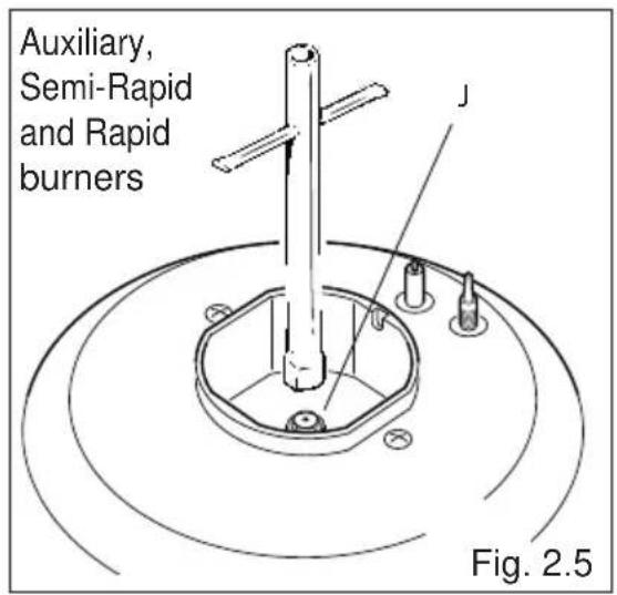
- Using a wrench, substitute the nozzle injectors "J" (figs. 2.5 - 2.6) with those most suitable for the kind of gas for which it is to be used (see "Table for the choice of the injectors").
The burners are constructed in such a way so as not to require the regulation of the primary air.

Adjusting of the Minimum of the Top Burners
Considering that in the minimum position the flame must have a length of about 4 mm and must remain lit even with a quick turn from the maximum position to that of minimum.
The flame adjustment is done in the following way:
- Turn on the burner
- Turn the tap to the MINIMUM position
• Take off the knob - With a thin screwdriver turn the screw "F" until adjustment is correct (fig. 2.7).
Normally for LPG, tighten up the regulation screw.

TABLE FOR THE CHOICE OF THE INJECTORS

Cat: II 2H3+
| Burners | Nominal Power kW | Reduced Power kW | G30 - 28-30 mbarG31 - 37 mbar | G20 - 20 mbar |
| ∅ Injector1/100 mm | ∅ Injector1/100 mm | |||
| Auxiliary (A) 1,00 0,30 50 7 | 2 (X) | |||
| Semi-Rapid (SR) 1,75 0,45 | 65 97 (Z) | |||
| Rapid (R) 3,00 0,75 85 115 | (Y) | |||
| Double-Ring (DR) 3,50 1,50 | 95 135 (T) |
| Increase of Air Necessary for Gas Combustion (2 m3/h x kW) | |
| Burners Air necessary for combustion (m | 3/h) |
| Auxiliary (A) 2,00 | |
| Semi-Rapid (SR) 3,50 | |
| Rapid (R) 6,00 | |
| Double-Ring (DR) | 7,00 |
Lubrication of the Gas Taps
The operations must be executed by a qualified technician.
IMPORTANT: All intervention regarding installation maintenance and conversion of the appliance must be fulfilled with original factory parts.
The manufacturer declines any liability resulting from the non-compliance of this obligation.
3 - ELECTRICAL INSTALLATION
IMPORTANT: The appliance must be installed in accordance with the manufacturer's instructions. Incorrect installation, for which the manufacturer accepts no responsibility, may cause damage to persons, animals and property.
The connection of the appliance to earth is mandatory. The manufacturer declines all responsibility for any inconvenience resulting from the inobservance of this condition.
Before carrying out any work on the electrical parts of the appliance, the appliance must be disconnected and locked off from the mains.
The appliance must be connected to the electrical network verifying that the voltage corresponds to the value indicated on the specifications plate and that the cables section of the electrical wiring can bear the load which is indicated on the rating plate.
We recommend that the appliance is connected by a suitably qualified person who will comply with the current IEE and local regulations.
It is recommended that the appliance is connected via a dedicated cooker circuit using a double pole cooker switch with a rating equal or greater than the total loading of the cooker, with a minimum opening between the contacts of 3 mm.
Alternative connection methods may be available as long as they conform to current IEE wiring regulations.
The power supply cable must not touch the hot parts and must be positioned so that it does not exceed 50 °C at any point.
Once the cooker has been installed, the switch must always be easily accessible within 2 metres.
ELECTRICAL FEEDER CABLE CONNECTION
WARNING: The power supply cable must be connected only by an authorised service agent in order to avoid a hazard.
If the power supply cable is damaged, it must be replaced only by an authorised service agent in order to avoid a hazard.
To connect the supply cable:
- Unhook the terminal board cover by inserting a screwdriver into the two hooks "A" (fig. 3.1).
- Unscrew the screw "D" and open completely the cable clamp "E" (fig. 3.2).
- Connect the phase, neutral and earth wires to terminal board "G" according to the diagram in fig. 3.3.
- Strain the feeder cable and block it with cable clamp "E" (by screwing screw "D").
- Close the terminal block cover (check the two hooks "A" are correctly hooked).
NOTE: The earth conductor must be left about 3 cm longer than the others.
IMPORTANT: To connect the power supply cable DO NOT unscrew the screws fixing the cover plate behind the terminal block.
POWER SUPPLY
230 V 50 Hz 4300 W
FEEDER CABLE SPECIFICATIONS Type "H05RR-F" or "H05VV-F"
3 × 2.5 mm2


Advice for the Users
1 - COOKING HOB
Fig. 1.1

GAS BURNERS
- Auxiliary burner (A) 1,00 kW
- Semi-rapid burner (SR) 1,75 kW
- Rapid burner (R) 3,00 kW
- Double-ring burner (DR) 3,50 kW
Caution!
Do not cover the hob with aluminium foil.
Notes:
• The electric ignition is incorporated in the knobs.
- The appliance has a safety valve system fitted, the flow of gas will be stopped if and when the flame should accidentally go out.
CAUTION:
If the burner is accidentally extinguished, turn the gas off at the control knob and wait at least 1 minute before attempting to relight.
CAUTION:
Gas hobs produce heat and humidity in the environment in which they are installed. Ensure that the cooking area is well ventilated by opening the natural ventilation grilles or by installing an extractor hood connected to an outlet duct that vents to the outside.
CAUTION:
If the hob is used for a prolonged time it may be necessary to provide further ventilation by opening a window or by increasing the suction power of the extractor hood (if fitted).
2 - CONTROL PANEL
Fig. 2.1
10 11

98765432
CONTROL PANEL - Controls description
- Electronic programmer (bottom main oven only)
- Fan oven switch/thermostat control knob (bottom main oven)
- Conventional oven switch control knob (top oven)
- Conventional oven thermostat control knob (top oven)
- Front left auxiliary burner control knob
- Rear left semi-rapid burner control knob
- Central double-ring burner control knob
- Rear right semi-rapid burner control knob
- Front right rapid burner control knob
Pilot lamps:
- Fan oven temperature indicator light
- Conventional oven on indicator light
NOTE:
The knob and symbols may vary.
Please note: This appliance incorporates a safety cooling fan which you will hear operating whenever the oven or grill is being used.
The cooling fan may even run on after the appliance has been switched off.
The duration of this time is dependent on several factors, including previous cooking temperature, duration and ambient temperature. Times in excess of 30 minutes are not uncommon.
3 - ELECTRONIC PROGRAMMER (BOTTOM MAIN OVEN ONLY)
The electronic programmer is a device which groups together the following functions:
• 24 hours clock with illuminated display
• Timer (up to 23 hours and 59 minutes)
- Program for automatic oven cooking (bottom main oven only)
- Program for semi-automatic oven cooking (bottom main oven only)
Description of the buttons:

Timer

Cooking time

End of cooking time

Simultaneously: Switching to manual and program reset.

To increase the numbers on the digital display

To decrease the numbers on the digital display.
Description of the illuminated symbols:
flashing - Programmer in
A automatic position but not programmed
illuminated - Programmer in
A automatic position with program inserted.

Automatic cooking taking place

Timer in operation

and A - flashing - Program error.
(The time of day lies between the calculated cooking start and end time).
Note:
Select a function by the respective button and, in 5 seconds, set the required time with the ▲ / ▽ buttons ("one-hand" operation).
After a power cut the display resets to zero and cancels the set programs.


Fig. 3.1
Caution: If the electricity supply is cut off (the display numbers will flash), the clock will reset and all the programs entered will be cancelled.
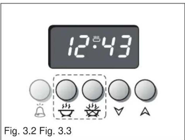
SETTING TIME OF DAY (fig. 3.2)
The programmer is provided with an electronic clock with luminous figures showing the hour and minutes.
The first time the oven is connected up to the electricity supply and after a power cut, three zeroes will flash on the programmer display.
To adjust the time, the two buttons must be pressed simultaneously and then the button or until the correct time is set.
Setting speed automatically increases if you keep the setting buttons pressed.
MANUAL OPERATION
To use the oven manually, i.e. without the programmer, you must cancel the flashing A by pressing the two buttons 🎨 simultaneously (the letter A will go out and the symbol 🎨 will come on).
CANCELLING A PROGRAMME
If the letter A is not flashing (which means that a cooking program has already been set) by pressing the two buttons simultaneously you will cancel the program and switch to manual.
If the oven is on, you must switch it off manually.

MINUTE MINDER
The minute counter function consists simply of an acoustic signal which can be set for a maximum of 23 hours 59 minutes.
If the letter A is flashing, press the two buttons simultaneously.
To set the time, press button and then button or until the required time appears on the display (fig. 3.4).
The symbol ⚠ will come on.
Countdown will begin immediately and can be seen on the display at any time by simply pressing button 🎨.
When the time expires, the symbol will go out and an intermittent acoustic signal will come on which can be switched off by pressing any of the buttons.
AUDIBLE SIGNAL
The audible signal sounds at the end of a minute minder cycle or of a cooking programme for a period of 7 minute.
The signal can be cancelled by pressing any function button.
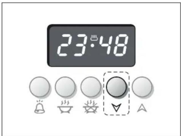
Pressing the ▼ button without having previously selected a function the frequency of the signal change. You can choose from three variations.
The selected signal is audible as long as the button \ is pressed.

Fig. 3.4 Fig. 3.5
SEMI - AUTOMATIC COOKING
This automatically switches the oven off after the required cooking time. There are two methods of semi-automatic cooking:
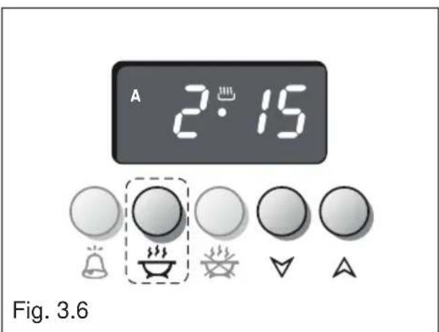
1° METHOD: Programming the cooking time (fig. 3.6)
- Set the cooking time by pressing button 📋 and then button to move forward or to move back if you have gone beyond the required time.
The letter A and the symbol will appear.
2° METHOD: Programming the end of cooking time (fig. 3.7)
- Set the end of cooking time by pressing button 🎨 and then button ↗ to move forward or ↘ to move back if you have gone beyond the required time.
The letter A and the symbol will appear.
Having programmed according to one of the above methods, set the temperature and function via the function selector and thermostat knob (see specific chapters).
The oven will come on immediately and when the set time or programmed end of cooking time expires, it will automatically switch off.
During cooking the letter A and the symbol remains on; press button to display the remaining time until end of cooking or press button to display the end of cooking time.
The cooking program can be cancelled at any time by pressing the two buttons simultaneously.
At the end of cooking, turn the oven knob to the off position the symbol will go out. The letter A will flash and the acoustic signal will come on - this can be switched off by pressing any of the buttons.
Reset the function selector and thermostat knob and set the programmer to manual by pressing the two buttons simultaneously.
Important: Also if oven is turned off automatically by the programmer, remember to turn to the off position the function selector and the thermostat knob. If not, when pressing two buttons simultaneously for manual use, the oven will start to operate.
Remember to press the two buttons simultaneously to be able to use the oven in manual setting.

AUTOMATIC COOKING
To cook in the oven in automatic mode follow the instructions below:
- Set the cooking time
- Set the end of cooking time
- Set the cooking temperature and function
These operations are carried out as follows:
- Set the cooking time by pressing button and then to move forward or to move back if you have gone beyond the required time (fig. 3.8).
The letter A and the symbol appear.
- Press button the cooking time already added to the clock time appear.
Set the end of cooking time by pressing button △if you go beyond the required time, you can go back by pressing button ▼
The symbol 🐘 go out and the letter A remains on (fig. 3.9).
If during the setting the letter A begins to flash on the display and the acoustic signal comes on, this indicates a programming error, i.e. the cooking cycle has been superimposed on the clock time. In this case alter the end of cooking time or the cooking time as above.
- Set the cooking temperature and function via the function selector and thermostat knob (see specific chapters).
The oven is now programmed and everything will work automatically; the oven will come on as required and finish cooking at the programmed time.
At the start of the cooking the symbol 🎨 appear.
During cooking the letter A and the symbol remains on; press button to display the remaining time until end of cooking or press button to display the end of cooking time.
The cooking program can be cancelled at any time by pressing the two buttons simultaneously.
At the end of cooking, the oven switch off, the symbol 🎨 go out, the letter A flash and the acoustic signal come on - this can be switched off by pressing any of the buttons.
Reset the function selector and thermostat knob and set the programmer to manual by pressing the two buttons simultaneously.
Important: Also if oven is turned off automatically by the programmer, remember to turn to the off position the function selector and the thermostat knob. If not, when pressing two buttons simultaneously for manual use, the oven will start to operate.
Remember to press the two buttons simultaneously to be able to use the oven in manual setting.

Fig. 3.8

IMPORTANT – MAIN OVEN NOT WORKING
If the main Oven is not working, it may have been accidentally set to “AUTOMATIC” or the power to the appliance was interrupted. If the Timer is showing the letter “A” as below or the time of day is flashing, the Oven may not turn on or be delayed in its operation.

Before requesting a service call, please refer to the timer set up instructions in this handbook and ensure the timer is set to "MANUAL" operation ensuring the cook symbol 🔊 appears in the timer as shown below.

NB. A service charge will be made if an engineer is called out to re-set the timer, as this is not covered by the guarantee.
4 - USE OF THE HOB BURNERS
Hob Burners
Each hob burner is controlled by a separate gas valve operated by a control knob (fig. 4.1) which has 3 positions marked on the control panel, these are:
- Symbol : Tap closed (burner off)
- Symbol ★ : High (maximum)
- Symbol : Low (minimum)
Push in and turn the knob anti-clockwise to the selected position.
The maximum aperture position permits rapid boiling of liquids, whereas the minimum aperture position allows slower warming of food or maintaining boiling conditions of liquids.
To reduce the gas flow to minimum, rotate the knob further anticlockwise to point the indicator towards the small flame symbol.
Other intermediate operating adjustments can be achieved by positioning the indicator between the maximum and minimum aperture positions, not between the maximum aperture and closed positions.
Note: When the hob is not being used, set the gas knobs to their closed positions and also close the cock valve on the gas bottle or the main gas supply line.

NOTE: The knob and symbols may vary.
Lighting of the Hob Burners
To ignite the burner, the following instructions are to be followed:
-
Press in the corresponding knob and turn counter-clockwise to the full flame position marked by the ⚠ symbol (fig. 4.1) and hold the knob in until the flame has been lit. In the case of a mains failure light the burner with a match or lighted taper.
-
Wait about ten seconds after the gas lighting before releasing the knob (starting time for the valve).
-
Adjust the gas valve to the desired power.
Important
If the burner flame should go out for some reason, the safety valve will automatically stop the gas flow.
To re-light the burner, return the knob to the closed “●” position, wait for at least 1 minute and then repeat the lighting procedure.
If your local gas supply makes it difficult to light the burner with the knob set to maximum, set the knob to minimum and repeat the operation.
Choice of Burner
On the control panel, near every knob there is a diagram that indicates which burner is controlled by that knob.
The suitable burner must be chosen according to the diameter and the capacity used.
The burners and pans must be used in accordance with the following instructions:
| Burner Size | Minimum Pan Diameter (cm) | Maximum Pan Diameter (cm) |
| Auxiliary 12 14 | ||
| Semi-Rapid 16 24 | ||
| Rapid 24 26 | ||
| Double-Ring 26 28 | ||
| Wok max 36 cm | ||
| Do not use pans with concave or convex bases. | ||
It is important that the diameter of the pot be suitable for the chosen burner so as not to compromise the high output of the burners and therefore waste energy.
A small pot on a large burner does not give you a boiling point in a shorter amount of time since the capacity of heat absorption of a liquid mass depends on the volume and the surface of the pot.
CAUTION: Make sure the pans are central to the burner for maximum stability and greater efficiency.
Make sure the pans are not in contact with the control knobs, otherwise the flame could overheat the knobs and permanently damage them.
Caution!
The cooking hob becomes very hot during operation.
Keep children well out of reach.
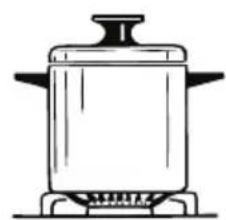

Fig. 4.2
CORRECT USE OF THE DOUBLE-RING BURNER
Only flat bottom pans of the correct size are to be placed on the pan support above the Double-ring burner.
When using a WOK, the supplied wok stand must be placed onto the pan stand to avoid any faulty operation of the Double-ring burner (fig. 4.3a). The wok should not be placed directly onto the pan support without the use of the supplied wok stand (fig. 4.3b).
IMPORTANT:
When using the wok stand it MUST ONLY BE PLACED over the pan support for the Double-ring burner (fig. 4.3a). Under no circumstances should the wok stand be placed under the pan supports (figs 4.4a - 4.4b). Incorrect placement of the wok stand in this manner may impinge the flame resulting in incomplete combustion and give rise to harmful levels of Carbon Monoxide (CO).


5 - HOW TO USE THE FAN OVEN (BOTTOM MAIN OVEN)
GENERAL FEATURES
Fan cooking is more economical and quicker than cooking in a conventional oven.
The moving hot air surrounds the food and penetrates it more quickly than in a conventional oven.
The oven is equipped with a circular element (2200 W) and a fan.
Note:
Upon first use, it is advisable to operate the oven at the maximum temperature (thermostat knob on position 250) for 60 minutes to eliminate any traces of grease from the electrical element.
Smells and fumes produced during this burn off process are not a cause of alarm. Adequate ventilation should however be provided in the room where the appliance is installed, e.g. by opening a window.
OPERATING PRINCIPLES
Heating and cooking in this oven are obtained by forced convection.
A fan sucks in the air contained in the oven muffle, which sends it through the circular heating element and then sends it back through the muffle. Before the hot air is sucked back again by the fan to repeat the described cycle, it envelops the food in the oven, provoking a complete and rapid cooking.
It is possible to cook several dishes simultaneously.
IMPORTANT
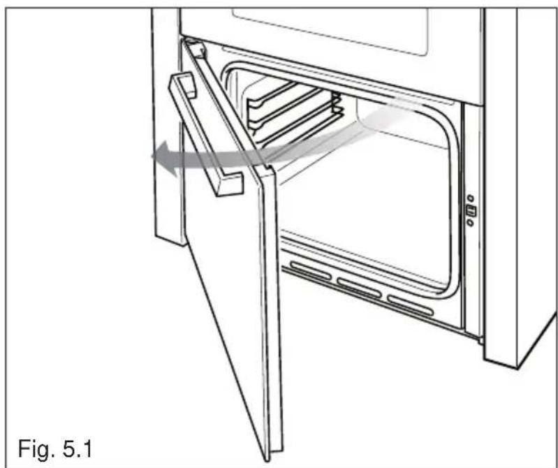
To open the bottom door operate as indicated in fig. 5.1.
Attention:
The oven door becomes very hot during operation.
WARNING:
The door is hot, use the handle.
ATTENTION - MOST IMPORTANT
Pay special attention not to touch the hot heating element inside the oven cavity.
SWITCH / TEMPERATURE SELECTOR
Rotate the knob clockwise to set the oven for one of the following functions:

Off as per fig. 5.2
Only the oven fan is on.
The fan operates without the heating element, this function can be used for defrosting.
50 to 250
The oven light is switched on.
The oven temperature can be set between 50° C - 250° C.
The set temperature has been reached when the temperature indicator light goes off.
Several different meals may be cooked simultaneously on various shelves, as the heated air circulates evenly throughout the oven.
The hot air system cooks more quickly than conventional static system, therefore the temperature should be set 15° C - 20° C below the values recommended in your recipe books.

6 - COOKING ADVICE
STERILISATION
Sterilisation of foods to be conserved, in full and hermetically sealed jars, is done in the following way:
a. Set the selector knob to position 185 °C and preheat the oven.
b. Fill the grill pan with hot water.
c. Set the jars onto the grill pan making sure they do not touch each other and the door and set the knob to position 135° C . When sterilisation has begun, that is, when the contents of the jars start to bubble, turn off the oven and let cool.
REGENERATION
Set the selector knob to position 150 °C.
Bread becomes fragrant again if wet with a few drops of water and put into the oven for about 10 minutes at the highest temperature.
ROASTING
To obtain classical roasting, it is necessary to remember:
- that it is advisable to maintain a temperature between 180°C and 200°C .
- that the cooking time depends on the quantity and the type of foods.
OVEN COOKING
Before introducing the food, preheat the oven to the desired temperature.
For a correct preheating operation, it is advisable to remove the tray from the oven and introduce it together with the food, when the oven has reached the desired temperature.
Check the cooking time and turn off the oven 5 minutes before the theoretical time to recuperate the stored heat.
SIMULTANEOUS COOKING OF DIFFERENT FOODS
The fan allows a simultaneous cooking of different foods. Different foods such as fish, cake and meat can be cooked together without mixing the smells and flavours together. This is possible since the fats and vapours are oxidized while passing through the electrical element and therefore are not deposited onto the foods.
The only precaution to follow are:
- The cooking temperatures of the different foods must be as close to as possible, with a maximum difference of 20° - 25°C .
- The introduction of the different dishes in the oven must be done at different times in relation to the cooking times of each one.
• The time and energy saved with this type of cooking is obvious.
7 - HOW TO USE THE CONVECTION OVEN (TOP OVEN)
WARNING:
The door is hot, use the handle.
During use the appliance becomes hot. Care should be taken to avoid touching heating elements inside the oven.
Attention: The oven door becomes very hot during operation. Keep children away.
GENERAL FEATURES
The convection oven is equipped with 3 electrical heating elements:
• 2 elements (upper and lower) for normal oven cooking;
- 1 grill element, on the top of the oven, for grilling which must be done with the oven door closed.
The input of the elements is:
- Upper element
- Lower element
- Grill element
Note:
Upon first use, it is advisable to operate the oven at the maximum temperature (thermostat knob on position 250° C ) for 60 minutes in the position and for another 15 minutes in the mode in order to eliminate any traces of grease from the electrical resistances.
OPERATING PRINCIPLES
Heating and cooking in the CONVENTIONAL oven are obtained in the following ways:
a. by normal convection
The heat is produced by the upper and lower heating elements.
b. by radiation
The heat is radiated by the infra red grill element (use with the oven door closed).

NOTE: The knob and symbols may vary.
THERMOSTAT KNOB (fig. 7.2)
This only sets the cooking temperature and does not switch the oven on.
Rotate clockwise until the required temperature is reached (from 50 °C to 250 °C).
The light between the thermostat and the function selector will illuminate when the oven is switched on.
FUNCTION SELECTOR KNOB (fig. 7.1)
Rotate the knob clockwise to set the oven for one of the following functions.

OVEN LIGHT
The oven is equipped with a light that illuminates the oven to enable visually controlling the food that is cooking.
This light is controlled by the function selector knob (fig. 7.1).
It remains on in all the cooking modes.

TRADITIONAL CONVECTION COOKING
The upper and lower heating elements are switched on. The heat is diffused by natural convection and the temperature must be regulated between 50 °C and 250 °C with the thermostat knob.
It is necessary to preheat the oven before introducing the foods to be cooked.
Recommended for:
For foods which require the same cooking temperature both internally and externally, i. e. roasts, spare ribs, meringue, etc.
eco ECO FUNCTION (ENERGY SAVING)
The upper and lower heating elements are switched on. The heat is diffused by natural convection.
This function reduces the appliance's energy consumption, it is therefore particularly beneficial for the gentle cooking of small quantities of food on a single shelf. It is not necessary to preheat the oven and use with the oven door closed.
Cooking times may be longer than standard functions.
Do not use this function to preheat the oven.
Recommended for:
Foods that require gentle cooking. To keep foods hot after cooking. To slowly heat already cooked foods.

GRILLING
The infra-red heating element is switched on. The heat is diffused by radiation.
Use with the oven door closed and the thermostat knob to between 50 °C and 200 °C.
For correct use see chapter "USE OF THE GRILL".
Before using the grill, preheat for about five minutes.
Always grill with the oven door closed and do not use the grill for longer than 30 minutes at any one time.
Caution: The oven door becomes very hot during operation.
Keep children well out of reach.
Recommended for:
Intense grilling action for cooking with a broiler; browning, crisping, "au gratin", toasting, etc.
USE OF THE GRILL
Leave to warm up for approximately 5 minutes with the door closed. Place the food inside positioning the rack as near as possible to the grill. Insert the drip pan under the rack to collect the cooking juices.
Grilling with the oven door closed and do not for longer than 30 minutes at any one time.
Attention: the oven door becomes very hot during operation. Keep children away.
OVEN COOKING
Before introducing the food, preheat the oven to the desired temperature.
For a correct preheating operation, it is advisable to remove the tray from the oven and introduce it together with the food, when the oven has reached the desired temperature.
Check the cooking time and turn off the oven 5 minutes before the theoretical time to recuperate the stored heat.
8 - OVEN TEMPERATURE GUIDE
| Cooking process | Oven heat Gas | mark | Electric oven temperature | |
| °C °F | ||||
| Keeping food hot, milk puddings | very cool 1⁄2 1 | 20 250 | ||
| Egg custards cool 1 | 40 275 | |||
| Rich fruit cakes, braising | cool 2 150 | 300 | ||
| Low temperature roasting, shortbread | moderate 3 | 60 325 | ||
| Victoria sandwich, plain fruit cake, baked fish | moderate 4 | 80 350 | ||
| Small cakes, choux pastry | fairly hot 5 | 90 375 | ||
| Short pastry, Swiss rolls, soufflés | fairly hot 6 | 200 400 | ||
| High temperature roasting, flaky pastry, scones | hot 7 220 | 425 | ||
| Puff pastry, bread very hot 8 | 230 450 | |||
| Small puff pastries, browning cooked foods | very hot 9 | 240 475 | ||
These temperatures relate to the centre oven temperature.
Remember to use ovenproof dishes and to adjust the oven temperature during cooking if necessary.
NOTE: Reduce the oven temperature by 10 – 20 °C for fan assisted ovens.
For dishes that take over an hour to cook, reduce the cooking time by 10 minutes per hour.
Do's and do not's
- Do always grill with the oven door closed.
- Do read the user instructions carefully before using the cooker for first time.
- Do allow the oven to heat for one and a half hours, before using for the first time, in order to expel any smell from the new oven insulation, without the introduction of food.
- Do clean your oven regularly.
- Do remove spills as soon as they occur.
- Do always use oven gloves when removing food shelves and tray from the oven.
- Do not allow children near the cooker when in use.
- Do not allow fat or oils to build up in the oven tray, or oven base.
- Do not place cooking utensils or plates directly onto the oven base.
- Do not grill food containing fat without using the grid.
- Do not cover the grilling grid with aluminium-foil.
- Do not use the oven tray for roasting.
- Do not place hot enamel parts in water. Leave them to cool first.
- Do not allow vinegar, coffee, milk, saltwater, lemon or tomato juice to remain in contact with enamel parts (inside the oven and on the oven tray).
- Do not use abrasive cleaners or powders that will scratch the surfaces and the enamel.
- Do not attempt to repair the internal workings of your cooker.
- Do remove the protective film before the first use.
• Fire risk! Do not store flammable material in the ovens or in the storage compartment.
For Your Safety
- The product should only be used for its intended purpose which is for the cooking of domestic foodstuffs.
- Under no circumstances should any external covers be removed for servicing or maintenance except by suitably qualified personnel
- Household appliances are not intended to be played with by children.
- Keep children away from the appliance during use.
• Children, or persons with a disability which limits their ability to use the appliance, should have a responsible person to instruct them in its use. The instructor should be satisfied that they can use the appliance without danger to themselves or their surroundings. - Do not operate your appliance by means of an external timer or separate remote-control system.
Important Notes
Installation, and any demonstration, information or adjustments are not included in the warranty.
The oven must be installed by a suitably qualified and registered person in accordance with the relevant Standards.
ATTENTION:
The appliance gets very hot, mainly around the cooking areas. It is very important that children are not left alone in the kitchen when you are cooking.
Important: The manufacturer declines all liability for possible damage caused by the use of unsuitable products to clean the appliance.
9 - CLEANING AND MAINTENANCE
It is advisable to clean when the appliance is cold and especially for cleaning the enamelled parts.
Avoid leaving alkaline or acidic substances (lemon juice, vinegar, etc.) on the surfaces.
Avoid using cleaning products with a chlorine or acidic base.
Clean surfaces with a damp cloth and use gentle, neutral cleaning products. Dry with a clean, dry cloth.
IMPORTANT: Do not use any abrasive products (e.g. certain types of sponge) and/or aggressive products (e.g. caustic soda, products containing corrosive substances), which could cause irreparable surface damage.
WARNING
When correctly installed, your product meets all safety requirements laid down for this type of product category. However special care should be taken around the rear or the underneath of the appliance as these areas are not designed or intended to be touched and may contain sharp or rough edges, that may cause injury.
Flexible Tube
From time to time, check the flexible tube connecting the gas supply to the cooker.
It must be always in perfect condition; in case of damage arrange for it to be replaced by a suitably qualified and registered installer.
Stainless steel hob: Spillage on the hob can usually be removed by a damp soapy cloth. More obstinate stains can be removed by using a proprietary stainless steel cleaning product that does not contain chlorine or acidic base.
Control panel facia: Clean very carefully with water and neutral soap; the cloth used must be rinsed well and must be free of any cleaning chemicals to avoid damaging any screen print on the facia.
Door, glass & painted surfaces: Clean very carefully with water and neutral soap; the cloth used must be rinsed well and must be free of any cleaning chemicals.
Pan stands & burner caps: Clean with a sponge and soapy water or proprietary cream cleaner. Alway dry throughly. DO NOT PUT IN THE DISHWASHER.
Burner bodies (aluminium alloy): They should be cleaned with soapy water and a clean cloth. For stubborn stains a proprietary cream or stainless steel cleaner may be used; however to maintain an uniform finish we would recommend the whole area is cleaned. NOTE: Please ensure the slots/castlellations are kept free of the any material/cleaner.
IMPORTANT:
Before any operation of cleaning and maintenance disconnect the appliance from the electrical supply.
ATTENTION:
Let the oven cool down and pay special attention not to touch the hot heating elements inside the oven cavity.
CAUTION:
Do not use abrasive substances or nonneutral detergents as these will irreparably damage the surface.
CAUTION:
Do not use a steam cleaner because the moisture can get into the appliance thus make it unsafe.
CAUTION:
Do not store flammable material in the oven or in the storage compartment.
CAUTION:
Do not use harsh abrasive cleaners or sharp metal scrapers to clean the oven door glass since they can scratch the surface, which may result in shattering of the glass.
GAS TAPS
- Do not let cleaning products come into contact with the valves.
• Periodic lubrication of the gas taps must be carried out by specialist personnel only. - In the event of operating faults in the gas taps, call the Service Department.
Burners and Grids
These parts must be cleaned using a sponge and soapy water or other suitable non-abrasive products. Dry with a soft cloth.
Warning! Not dishwasher safe.
After cleaning, the burners and their flame spreaders must be well dried and correctly replaced.
It is very important to check that the burner flame spreader and the cap have been correctly positioned. Failure to do so can cause serious problems.
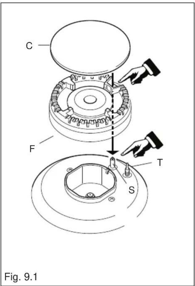
Check that the electrode "S" (figs. 9.1 - 9.3) next to each burner is always clean to ensure trouble-free sparking.
Check that the sensor "T" (figs. 9.1 - 9.3) next to each burner is always clean to ensure correct operation of the safety valves.
Both the sensor and ignition plug must be very carefully cleaned.
Note: To avoid damage to the electric ignition do not use it when the burners are not in place.
Note: Continuous use may cause a change in the glaze around the burners and grids, corresponding to the areas exposed to the heat. This is a natural phenomenon and does not prevent the parts from working properly.
Correct Positioning of the Auxiliary, Semi-Rapid and Rapid Burners
It is very important to check that the burner flame spreader "F" and the cap "C" have been correctly positioned (see figs. 9.1 and 9.2).
Failure to do so can cause serious problems.
Correct Position of the Double-Ring Burner
The double-ring burner must be correctly positioned (see fig. 9.5); the burner ribs must be fitted in their housing as shown by the arrow.
The burner correctly positioned must not rotate (fig. 9.4).
Then position the cap "A" and the ring "B" (figs. 9.4 - 9.5)


ASSEMBLING AND DISMANTLING OF THE SIDE RUNNER FRAMES
- Assemble the wire racks to the oven walls using the 2 screws (figs. 9.6a - 9.6b).
- Slide the tray and rack into the runners (figs. 9.7a - 9.7b).
The rack must be fitted so that the safety notch, which stops it sliding out, faces the inside of the oven; the guard rail should be at the back.
• To dismantle, operate in reverse order.


Inside of Oven
The oven should always be cleaned after use when it has cooled down.
The cavity should be cleaned using a mild detergent solution and warm water.
Suitable proprietary chemical cleaners may be used after first consulting with the manufacturers recommendations and testing a small sample of the oven cavity. Abrasive cleaning agents or scouring pads/cloths should not be used on the cavity surface.
NOTE: The manufacturers of this appliance will accept no responsibility for damage caused by chemical or abrasive cleaning.
Let the oven cool down and pay special attention not to touch the hot heating elements inside the oven cavity.
REPLACING THE HALOGEN OVEN LIGHT
WARNING: Ensure the appliance is switched off before replacing the lamp to avoid the possibility of electric shock.
- Let the oven cavity and the heating elements cool down.
- Switch off the electrical supply.
- Remove the protective cover "C" (fig. 9.8).
- Replace the halogen lamp “B” with a new one suitable for high temperatures having the following specifications: 220-240 V or 230-240 V, 50 Hz and same power (check watt power as stamped in the bulb itself) as the replaced lamp.
IMPORTANT WARNING: Never replace the lamp with bare hands; contamination from your fingers can cause premature failure. Always use a clean cloth or gloves.
- Refit the protective cover "C".
NOTE: Oven bulb replacement is not covered by your guarantee.
The intended purpose of the lamps, fitted on this appliance, is to illuminate the oven cavity and thus help the user to better monitor the food while cooking. These lamps are not suitable for other usage (e.g. environments lighting).
This product contains more than one light source of energy efficiency class G.


Fig. 9.8
TOP OVEN DOOR REMOVING THE OVEN DOOR
The oven door can easily be removed as follows:
- Open the door to the full extent (fig. 9.9a).
- Open the lever A completely on the left and right hinges (fig. 9.9b).
- Hold the door as shown in fig. 9.9.
- Gently close the door (fig. 9.9c) until left and right hinge levers A are hooked to part B of the door (fig. 9.9b).
- Withdraw the hinge hooks from their location following arrow C (fig. 9.9d).
- Rest the door on a soft surface.
• To replace the door, repeat the above steps in reverse order.


Important!
Always keep a safe distance from the door hinges, paying special attention to position of your hands.
If the door hinges are not correctly hooked, they could unhook and close suddenly and unexpectedly with risk of injury.


10 - GUARANTEE
Your new “De’Longhi” product comes with 12-month guarantee covering all parts and labour.
If your appliance proves to be defective as a result of faulty materials or workmanship during the guarantee period, these parts will be repaired or replaced free of charge.
AFTER SALES SERVICE
IMPORTANT – MAIN OVEN NOT WORKING: if the main oven is not working please make sure electronic programmer is set to MANUAL operations (see pag. 32).
Should you require service, spares or product information and advice:
- Please Telephone 01908 733 010 (Great Britain)
028 9744 2461 (Northern Ireland - Mon to Fri 9:00am to 5:00pm Excluding Bank Holidays)
- Details of your purchase receipt will be required if you require service within the first 12-month of purchase.
- The rights and benefits under this guarantee are additional to your statutory rights, which are not affected by this guarantee.
- The manufacturer undertakes within the specified period, to repair or replace free of charge any parts of the appliance found to be defective provided that:
• We are promptly informed of the defect.
- The appliance is installed and used in accordance with the written instructions enclosed with the appliance.
- The appliance is used only on an electrical supply as indicated on the rating label fixed to the appliance.
- The appliance has not been altered in any way or subject to misuse or repaired by a person other than an authorised service agent.
- No rights are given under this guarantee to a person acquiring the appliance second hand or for commercial, semi-commercial or communal use.
- This guarantee applies throughout the UK and Channel Islands.
- Any repaired or replacement appliances will be guaranteed on these terms for the unexpired portion of the guarantee.

Descriptions and illustrations in this booklet are given as simply indicative. The manufacturer reserves the right, considering the characteristics of the models described here, at any time and without notice, to make eventual necessary modifications for their construction or for commercial needs.
www.delonghi-cookers.co.uk
- DEAR CUSTOMER
- IMPORTANT INFORMATION FOR CORRECT DISPOSAL OF THE PRODUCT IN ACCORDANCE WITH EC DIRECTIVE 2012/19/EC
- DECLARATION OF CE CONFORMITY
- ENERGY LABELLING/ECODESIGN
- USE OF THE APPLIANCE, ENERGY SAVING TIPS
- OVEN
- HOB
- GAS FIRED BURNERS
- ADVICE FOR THE INSTALLER
- IMPORTANT
- WARNING
- INSTALLATION
- BACKGUARD
- IT IS MANDATORY TO INSTALL THE BACKGUARD
- MOVING THE COOKER
- ANTI-TILT BRACKET
- ATTENTION
- PROVISION FOR VENTILATION
- NOTE: REGARDLESS OF ROOM SIZE, ALL ROOMS CONTAINING THE APPLIANCE MUST HAVE DIRECT ACCESS TO THE OUTSIDE AIR VIA A WINDOW THAT CAN BE OPENED OR EQUIVALENT
- INSTALLATION & SERVICE REGULATIONS (UNITED KINGDOM)
- GAS CONNECTION
- INSTALLATION TO NATURAL GAS
- INSTALLATION TO LP GAS
- NOTES
- GAS CONNECTION (FIGS. 2.2, 2.3, 2.4)
- CONVERSION TO NATURAL GAS OR TO LPG
- INJECTORS REPLACEMENT OF TOP BURNERS
- ADJUSTING OF THE MINIMUM OF THE TOP BURNERS
- TABLE FOR THE CHOICE OF THE INJECTORS
- LUBRICATION OF THE GAS TAPS
- ELECTRICAL INSTALLATION
- ELECTRICAL FEEDER CABLE CONNECTION
- POWER SUPPLY
- FEEDER CABLE SPECIFICATIONS TYPE "H05RR-F" OR "H05VV-F
- ADVICE FOR THE USERS
- COOKING HOB
- GAS BURNERS
- CAUTION
- CONTROL PANEL
- CONTROL PANEL - CONTROLS DESCRIPTION
- PILOT LAMPS
- NOTE
- THE KNOB AND SYMBOLS MAY VARY
- ELECTRONIC PROGRAMMER (BOTTOM MAIN OVEN ONLY)
- DESCRIPTION OF THE BUTTONS
- DESCRIPTION OF THE ILLUMINATED SYMBOLS
- SETTING TIME OF DAY (FIG. 3.2)
- MANUAL OPERATION
- CANCELLING A PROGRAMME
- MINUTE MINDER
- AUDIBLE SIGNAL
- SEMI - AUTOMATIC COOKING
- ° METHOD: PROGRAMMING THE COOKING TIME (FIG. 3.6)
- ° METHOD: PROGRAMMING THE END OF COOKING TIME (FIG. 3.7)
- AUTOMATIC COOKING
- IMPORTANT – MAIN OVEN NOT WORKING
- USE OF THE HOB BURNERS
- HOB BURNERS
- LIGHTING OF THE HOB BURNERS
- CHOICE OF BURNER
- CORRECT USE OF THE DOUBLE-RING BURNER
- HOW TO USE THE FAN OVEN (BOTTOM MAIN OVEN)
- GENERAL FEATURES
- OPERATING PRINCIPLES
- ATTENTION - MOST IMPORTANT
- SWITCH / TEMPERATURE SELECTOR
- COOKING ADVICE
- STERILISATION
- REGENERATION
- ROASTING
- OVEN COOKING
- SIMULTANEOUS COOKING OF DIFFERENT FOODS
- HOW TO USE THE CONVECTION OVEN (TOP OVEN)
- BY NORMAL CONVECTION
- BY RADIATION
- THERMOSTAT KNOB (FIG. 7.2)
- FUNCTION SELECTOR KNOB (FIG. 7.1)
- OVEN LIGHT
- TRADITIONAL CONVECTION COOKING
- RECOMMENDED FOR
- ECO ECO FUNCTION (ENERGY SAVING)
- GRILLING
- USE OF THE GRILL
- OVEN TEMPERATURE GUIDE
- DO'S AND DO NOT'S
- FOR YOUR SAFETY
- IMPORTANT NOTES
- CLEANING AND MAINTENANCE
- FLEXIBLE TUBE
- GAS TAPS
- BURNERS AND GRIDS
- WARNING! NOT DISHWASHER SAFE
- CORRECT POSITIONING OF THE AUXILIARY, SEMI-RAPID AND RAPID BURNERS
- CORRECT POSITION OF THE DOUBLE-RING BURNER
- ASSEMBLING AND DISMANTLING OF THE SIDE RUNNER FRAMES
- INSIDE OF OVEN
- REPLACING THE HALOGEN OVEN LIGHT
- TOP OVEN DOOR REMOVING THE OVEN DOOR
- GUARANTEE
- AFTER SALES SERVICE
- IMPORTANT – MAIN OVEN NOT WORKING: IF THE MAIN OVEN IS NOT WORKING PLEASE MAKE SURE ELECTRONIC PROGRAMMER IS SET TO MANUAL OPERATIONS (SEE PAG. 32)
Brand : DELONGHI
Model : DDC 707 DF
Category : Cooker