
DEGHSL90 - Cooker DELONGHI - Free user manual and instructions
Find the device manual for free DEGHSL90 DELONGHI in PDF.


| Brand | DeLonghi |
| Model | DEGHSL90 |
| Product Type | Freestanding Cooker (Range) |
| Category | Cooker |
| Width | 90 cm |
| Depth | 60 cm |
| Height | 85 cm (approx.) |
| Weight | 65 kg (approx.) |
| Fuel Type | Natural Gas or LPG (convertible) |
| Oven Type | Gas oven with grill |
| Number of Gas Burners | 5 burners with different power levels |
| Ignition | Automatic electric ignition |
| Safety Features | Flame failure safety devices on all burners |
| Oven Functions | Gas oven with thermostat control and grill function |
| Control Settings | Manual valves and thermostat dials |
| Cleaning | Easy-clean enamel interior |
| Door Type | Drop-down oven door with inner glass |
| Storage | Storage compartment at the base |
| Electrical Supply | 220-240 V, 50/60 Hz (for ignition and oven light) |
| Gas Supply | 20 mbar (Natural Gas) / 28-30 mbar (LPG) adjustable |
| Finish | Stainless steel and black enamel |
| Additional Features | Integrated oven light |
| Repairability | Spare parts available; replaceable burners, thermostats, and seals |
| Warranty | Standard DeLonghi warranty (depending on region) |
Frequently Asked Questions - DEGHSL90 DELONGHI
User questions about DEGHSL90 DELONGHI
0 question about this device. Answer the ones you know or ask your own.
Ask a new question about this device
Download the instructions for your Cooker in PDF format for free! Find your manual DEGHSL90 - DELONGHI and take your electronic device back in hand. On this page are published all the documents necessary for the use of your device. DEGHSL90 by DELONGHI.
USER MANUAL DEGHSL90 DELONGHI
INSTALLATION and SERVICE INSTRUCTIONS USE and CARE INSTRUCTIONS
DEGHSL60
DEGHSL75
DEGHSL90
GAS COOKTOPS
distributed by
DeLonghi Australia Pty Ltd
DeLonghi New Zealand Ltd
DēLonghi
Dear Customer,
Thank you for having purchased and given your preference to our product.
The safety precautions and recommendations reported below are for your own safety and that of others. They will also provide a means by which to make full use of the features offered by your appliance.
Please keep this booklet in a safe place. It may be useful in future, either to yourself or to others in the event that doubts should arise relating to its operation.
This appliance must be used only for the task it has explicitly been designed for, that is for cooking foodstuffs. Any other form of usage is to be considered as inappropriate and therefore dangerous.
The manufacturer declines all responsibility in the event of damage caused by improper, incorrect or illogical use of the appliance or be faulty installation.
This cooktop has been designed and constructed in accordance with the following codes and specifications:
AGA101 (AS 4551) Approval Requirements for Domestic Gas cooking appliances
AS/NZS 60335.1 General Requirements for Domestic electrical appliances
AS/NSZ 60335.2.102 Particular Requirements for Domestic electrical cooking appliances
AS/NZS CISPR 14.1 Electromagnetic Compatibility Requirements
PRODUCT LABEL
IMPORTANT SAFETY PRECAUTIONS AND RECOMMENDATIONS
IMPORTANT: This appliance is designed and manufactured solely for the cooking of domestic (household) food and is not suitable for any non domestic application and therefore should not be used in a commercial environment.
The appliance guarantee will be void if the appliance is used within a non domestic environment i.e. a semi commercial, commercial or communal environment.
Read the instructions carefully before installing and using the appliance.
• After having unpacked the appliance, check to ensure that it is not damaged.
In case of doubt, do not use it and consult your supplier or a professionally qualified technician.
- Packing elements (i.e. plastic bags, polystyrene foam, nails, packing straps, etc.) should not be left around within easy reach of children, as these may cause serious injuries.
- Some appliances are supplied with a protective film on steel and aluminium parts. This film must be removed before using the appliance.
- IMPORTANT: The use of suitable protective clothing/gloves is recommended when handling or cleaning this appliance.
- Do not attempt to modify the technical characteristics of the appliance as this may become dangerous to use. The manufacturer declines all responsibility for any inconvenience resulting from the inobservance of this condition.
- CAUTION: This appliance must only be installed in a permanently ventilated room in compliance with the applicable regulations.
- Do not carry out cleaning or maintenance operations on the appliance without having previously disconnected it from the electric power supply.
- Do not use a steam cleaner because the moisture can get into the appliance thus make it unsafe.
- Do not touch the appliance with wet or damp hands (or feet).
- Do not use the appliance whilst in barefoot.
- If you should decide not to use this appliance any longer (or decide to substitute another model), before disposing of it, it is recommended that it be made inoperative in an appropriate manner in accordance to health and environmental protection regulations, ensuring in particular that all potentially hazardous parts be made harmless, especially in relation to children who could play with unused appliances.
- The various components of the appliance are recyclable. Dispose of them in accordance with the regulations in force in your country. If the appliance is to be scrapped, remove the power cord.
• After use, ensure that the knobs/controls are in the off position. - Children should be supervised to ensure that they do not play with this appliance.
- This appliance is not intended for use by persons (including children) with reduced physical, sensory or mental capabilities, or lack of experience and knowledge, unless they have been given supervision or instruction concerning use of the appliance by a person responsible for their safety.
- The manufacturer declines all liability for injury to persons or damage to property caused by incorrect or improper use of the appliance.
- WARNING: During use the appliance and its accessible parts become hot; they remain hot for some time after use.
- Care should be taken to avoid touching heating elements on the hob.
- To avoid burns and scalds, young children should be kept away.
- Make sure that electrical cables connecting other appliances in the proximity of the cooktop cannot come into contact with the hob.
-
WARNING: Unattended cooking on a hob with fat or oil can be dangerous and may result in fire. NEVER try to extinguish a fire with water, but switch off the appliance and then cover flame e.g. with a lid or a fire blanket.
-
CAUTION: The cooking process has to be supervised. A short term cooking process has to be supervised continuously.
- WARNING: Danger of fire: do not store items on the cooking surfaces.
- WARNING: If the hob is cracked or otherwise damaged by falling objects etc., disconnect the appliance from the electrical power supply to avoid the possibility of electric shock and call Customer Service.
- WARNING: When correctly installed, your product meets all safety requirements laid down for this type of product category. However special care should be taken around the underneath of the appliance as this area is not designed or intended to be touched and may contain sharp or rough edges, that may cause injury.
• DO NOT USE OR STORE FLAMMABLE MATERIALS NEAR THIS APPLIANCE.
• DO NOT SPRAY AEROSOLS IN THE VICINITY OF THIS APPLIANCE WHILE IT IS IN OPERATION.
• DO NOT MODIFY THIS APPLIANCE. - WHERE THIS APPLIANCE IS INSTALLED IN MARINE CRAFT OR IN CARAVANS, IT SHALL NOT BE USED AS A SPACE HEATER.'
INSTALLATION
CAUTION:
■ Important: The use of suitable protective clothing/gloves is recommended when handling or cleaning of this appliance.
This appliance must be installed in accordance with these installation instructions, local gas fitting regulations, municipal building codes, w supply regulations, electrical wiring regulations, - Gas Installations and ony other relevant statutory regulations.
■ The appliance must be housed in heat-resistant units.
■ We would point out that the adhesive which bonds the plastic laminate to the furniture must withstand temperatures not less than 150° C to avoid delamination.
■ Do not install the appliance near inflammable materials (eg. curtains).
■ This appliance is to be installed only by an authorised person.
■ This appliance shall be only be serviced by authorized personnel.
■ Incorrect installation, for which the manufacturer accepts no responsibility, may cause personal injury of damage.
■ Always disconnect the appliance from mains power supply before carrying out any maintenance operations or repairs.
In the room where the appliance is installed, there must be enough air to allow the gas to burn correctly, according to the current local regulations.
WARNING!
When correctly installed, your product meets all safety requirements laid down for this type of product category. However special care should be taken around the underneath of the appliance as this area is not designed or intended to be touched and may contain sharp or rough edges, that may cause injury.
ELECTRICAL REQUIREMENTS
■ The appliance must be connected to the mains checking that the voltage corresponds to the value given in the rating plate and that the electrical cable sections can withstand the load specified on the plate.
■ The plug must be connected to an earthed socket in compliance with safety standards.
■ If the appliance is supplied without plug, fit a standard plug which is suitable for the power consumed by the appliance.
■ The wires in the power cable are coloured in accordance with the following code: Green/Yellow = Earth, Blue = Neutral, Brown = Active.
If the colours of the wires in the power cable to the appliance do not correspond with the coloured markings identifying the terminals in the junction terminal, proceed as follows:
- The wire which is coloured green and yellow must be connected to the terminal marked "E" (Earth) or " 1/= " coloured Green.
-
The wire which is coloured blue must be connected to the terminal marked "N" (Neutral) or coloured Black.
-
The wire which is coloured brown must be connected to the terminal marked "L" (Live) or "A" (Active) or coloured Red.
■ A suitable isolating switch providing full disconnection from the mains power supply (under overvoltage category III conditions) shall be incorporated in the permanent wiring, mounted and positioned to comply with the local wiring rules and regulations. The isolating switch must be of an approved type and provide a 3 mm air gap contact separation in all poles (or in all active [phase] conductors if the local wiring rules allow for this variation of the requirements).
■ The power supply cable must not touch the hot parts and must be positioned so that it does not exceed 50° C above ambient.
■ Once the appliance has been installed, the switch or socket must always be accessible.
If the supply cord is damaged it must be replaced by the manufacturer or its Service Agent or a similarly qualified person in order to avoid a hazard.
N.B. The connection of the appliance to earth is mandatory.
If the installation requires alterations to the domestic electrical system call a qualified electrician.
He should also check that the socket cable section is suitable for the power drawn by the appliance.
Replacing the power cord must be done by a qualified electrician in accordance with the instructions supplied by the manufacturer and in compliance with established electrical regulations.
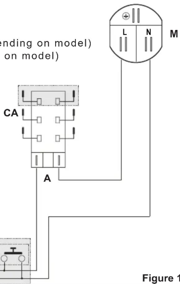
ELECTRIC DIAGRAM KEY
A Ignition coil
PA Ignition switches group (4÷6 depending on model)
CA Spark electrodes (4÷6 depending on model)
M Terminal block
DEGHSL75 model only:
If fitted with a 6-spark ignition coil, the 6th outlet, not used, is earthed by a ground strap in contact with the basepan.
![graph TD A["Component 1"] --> B["Component 2"] B --> C["Component 3"] C --> D["Component 4"] D --> E["Component 5"] E --> F["Component 6"] F --> G["Component 7"]](/content/2026/08/1624973/images/570a2046d2a9f450da5a1c25c2d71563e258b056ab4df4db2d17174b522e504e.jpg)
CLEARANCES
Installation clearances and protection of combustible surfaces shall comply with the current local regulations e.g. AS/NZS5601 - Gas Installations code.


Figure 2cFigure 2
| Measures (mm) | |||||||
| Description A B | C D E F | (minimum) | G (minimum) | ||||
| Model DEGHSL60 6 | 00 510 | 49 (*) 56 | 0 480 6 | 0 (**) 20 | 0 (***) | ||
| Model DEGHSL75 7 | 50 510 | 49 (*) 56 | 0 480 6 | 0 (**) 20 | 0 (***) | ||
| Model DEGHSL90 9 | 00 510 | 49 (*) 84 | 0 480 6 | 0 (**) 20 | 0 (***) | ||
(*) From top of countertop
(**) Between the back edge of the cut-out and the back of the countertop.
(***) From the side edge of the cut-out to any vertical combustible surface. If this distance is less than 200 mm, the surface shall be protected (in accordance with AS/NZS5601) to a height of not less than 150 mm above the hob for the full dimension (width or depth) of the cooking surface area.
IMPORTANT NOTE:
THIS APPLIANCE SHALL NOT BE USED AS A SPACE HEATER, ESPECIALLY IF INSTALLED IN MARINE CRAFT OR CARAVANS.
The installation shall comply with the dimensions in figs. 2a, 2b bearing in mind that:
■ A 40mm ventilation gap must be provided between the bottom of the appliance and any cabinetry, draw unit, thermal protection barrier or appliance.
If the cooktop is installed directly above an oven (which does not have a cooling fan motor) or if its base is accessible through a cupboard or drawer space after installation, a thermal protection barrier must be installed below the base of the cooktop as indicated in fig. 2c.
■ If the oven installed below the cooktop has a cooling fan motor, the thermal protection barrier is not required.
If the cooktop is installed above an oven, the two appliances shall be connected to the gas and/or electrical supply with independent connections.
■ Overhead clearances - In no case shall the clearance between the highest part of the hob and a range hood be less than 600 mm, or for an overhead exhaust fan 750 mm. Any other downward facing combustible surface less than 600 mm above the highest part of the hob shall be protected for the full width and depth of the cooking surface area in accordance with local regulations in force. However, in no case shall this clearance to any surface be less than 450 mm.
Standards requirement
Temperature of nearby surfaces. Australian and New Zealand Gas Installation Standards (AS/NZS5601) require a cooktop to be installed so that the surface temperature of any nearby combustible surface will not exceed 65° C above ambient.
This is typically achieved by:
■ having the cooktop spaced away from the wall (see figures 2a, 2b);
AND
■ protecting the wall to a height of at least 150 mm along its length (minimum height of non-combustible material when used on adjacent walls) with non-combustible surface materials such as:
- 5 mm-thick ceramic tiles (these alone are adequate);
- tempered glass or sheetmetal, minimum thickness 0.4 mm (acceptable when used in front of a fire resistant material).
FASTENING THE COOKTOP
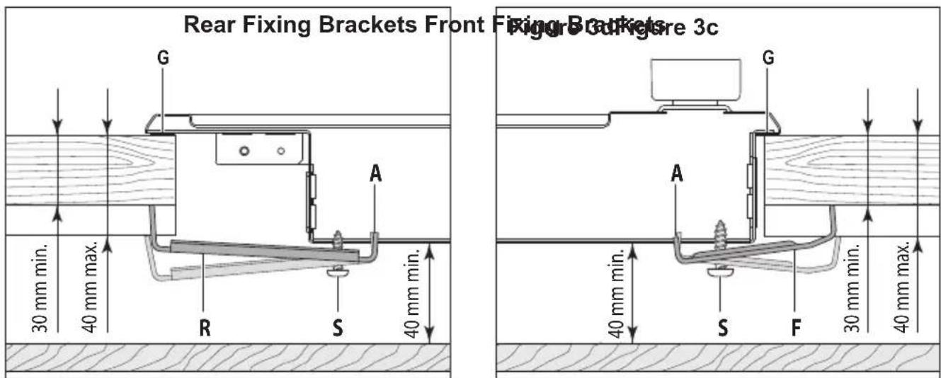
Each cooktop is provided with an installation kit including brackets and screws for fastening the cooktop to benches from 30 to 40mm thick.
Models DEGHSL60, DEGHSL75 (fig. 3a): The kit includes two "F" type brackets (for the front of the cooktop), two "R" type brackets (for the rear of the cooktop) and four self-threading screws "S".
Model DEGHSL90 (fig. 3b): The kit includes four "F" type brackets (for the front of the cooktop), three "R" type brackets (for the rear of the cooktop) and seven self-threading screws "S".
- Cut the unit according to the dimensions in fig. 2a.
- Stretch gasket "G" over the edge of the hole made, being careful to overlay the junction edges.
- Fasten the brackets "F" and "R" to the appropriate socket holes, without tightening the screws "S" for the moment. Make sure that the tabs are mounted correctly, as shown (figs. 3a, 3b, 3c, 3d). Rotate the tabs so that the cooktop can be put into the cutout.
- Put the cooktop into the cutout and position it correctly.
- Put the brackets "F" and "R" into place; tooth "A" of the brackets should go into the hole (figs. 3c, 3d).
- Tighten screws "S" until the cooktop is completely secured to the bench.
- Using a sharp cutter or trimmer knife, trim the excess sealing material around the edge of the cooktop.
Take care not to damage the workbench.


GAS SUPPLY
■ This appliance is suitable for use with Natural Gas or ULPG (Check the "gas type" sticker attached to the appliance).
■ For Natural Gas the gas supply must be regulated to obtain a pressure of 1 kPa:
-with the two semi-rapid (SR) burners operating at the maximum - model DEGHSL60 only;
-with the triple-ring (TR) burner operating at the maximum - model DEGHSL75 only;
-with the dual (DB) burner operating at the maximum (inside and outside flames in simultaneously at the maximum) - model DEGHSL90 only.
■ For ULPG models connect the gas supply directly to the appliance test point adaptor (supplied with the conversion kit) and ensure that the supply pressure is regulated to 2.75 kPa.
■ Do NOT force the "elbow" rotation prior to loosening nut.
■ Do NOT over tighten the nut at the "elbow".
- After connecting the gas supply, check the piping and connections for leaks using a soap and water solution. The presence of bubbles indicates a leak,
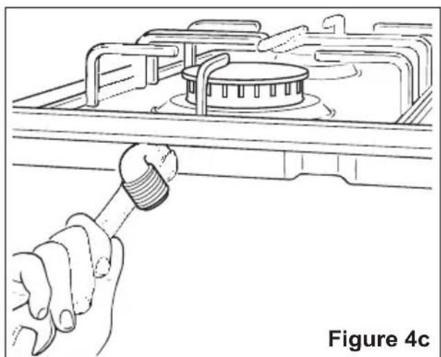


tighten or replace connections as appropriate.
Warning: Do not use any naked flame to check for leaks.
- The operation of the appliance MUST be tested before leaving.
- Adjust the test point pressure or supply pressure to the value which is appropriate for the gas type.
- Turn on the appliance gas controls and light each burner. Check for a well defined blue flame without any yellow tipping. If any abnormality is evident then check that the burner flame spreader and burner cap/s are both located properly.
- Check the minimum burner setting by quickly rotating the gas control knob from the maximum to the minimum position, the flame must not go out. If adjustment is required carry out the "MINIMUM BURNER SETTING ADJUSTMENT" procedure described below.
- If satisfactory performance cannot be obtained, the installer shall check the installation and notify the local gas supply authority for a gas supply problem, or if it is an appliance problem, our Customer Service Centre should be called to obtain the nearest authorized Delonghi Service Agent.
- Where the appliance data plate cannot be easily read with the appliance in the installed position the duplicate data plate must be attached to adjacent surface and the duplicate Natural gas / ULPG conversion label should also be included where a Natural gas / ULPG conversion has been completed.
INSTALLATION WITH A FLEXIBLE HOSE ASSEMBLY
If this appliance has to be installed with a hose assembly, the installer shall refer to the network operator or gas supplier for confirmation of the gas type, if in doubt.
■ When used with a flexible hose, the connector on the wall should be between 800 mm to 850 mm above the floor and in the region outside the width of the appliance to a distance of 250 mm.
The supply connection point shall be accessible with the appliance installed.
■ Flexible hose assemblies should be AS/NZS 1869 Class B or Class D certified.
The thread connection shall be Rp 1/2" (ISO 7-1) male.
■ IMPORTANT WARNING: After connection the installer must check that the hose is not kinked, subjected to abrasion or permanently deformed. The installer must check also that the hose is not near (or in contact) with any hot surfaces e.g. base of metal hotplate, underbench oven etc.
■ The hose assembly shall be as short as practicable and comply with relevant AS/NZS5601 requirements.
■ IMPORTANT WARNING: The installer shall ensure the hose assembly is restrained from accidental contact with the flue outlet of an underbench oven.
TABLE FOR THE CHOICE OF THE INJECTORS
| Natural Gas ULPG | ||||
| Test Point Pressure [kPa] 1.0 2.75 | ||||
| BURNER | Injector Orifice Dia. [mm] | Gas Consumption [MJ/h] | Injector Orifice Dia. [mm] | Gas Consumption [MJ/h] |
| Auxiliary (AUX) 0.92 3.90 0.56 | 3.90 | |||
| Semi-rapid (SR) 1.17 6.50 0.70 | 6.20 | |||
| Rapid (R) (1) 1.54 11.75 0.98 | 11.75 | |||
| Triple-ring compact (TRC) (2) | 1.48 10.70 0.88 9.60 | |||
| Triple-ring (TR) (3) 1.68 13.70 | 1.04 14.10 | |||
| Dual (DB) - inner crown (4) 0.72 2.40 0.43 | 2.10 | |||
| Dual (DB) - outer crown (4) | 1.23 (x2) | 13.80 | 0.66 (x2) | 11.40 |
(1) Only for the models DEGHSL75, DEGHSL90
(2) Only for the model DEGHSL60
(3) Only for the model DEGHSL75
(4) Only for the model DEGHSL90
(Note: Gas type sticker and data plate are attached to the underside of the base of the appliance.)
CONVERSION PROCEDURE (to convert to Natural gas or to ULPG) REPLACING THE INJECTORS
The conversion procedure must be carried out only by an authorised person.
This appliance is suitable for use with Natural gas or Universal LPG (check the “gas type” sticker attached to the appliance).
The nominal gas consumption and injector size details are provided in table above.
To replace the injectors proceed as follows:
■ Remove pan supports and burners from the cooktop.
■ Using a wrench, substitute the injectors "J" (figs. 5a, 5b, 5c, 5d) with those most suitable for the kind of gas for which it is to be used (see table above).
■ Affix to the appliance the warning label stating that the cooktop has been converted for use with Natural gas/ULPG (supplied with the Natural gas/ULPG conversion kit). A second Natural gas/ULPG conversion label should also be affixed to an adjacent surface along with the duplicate data plate.
IMPORTANT
If the cooktop is suitable for use with Natural gas and must be converted for use with Universal LPG, before connecting to gas main remove the appliance gas regulator
and replace with test point adaptor (see figs. 4a, 4b).
■ If the cooktop is suitable for use with Universal LPG and must be converted for use with Natural gas, before connecting to the gas main remove the appliance test point adaptor and replace with gas regulator (see figs. 4a, 4b).
NOTE:
Gas regulator and test point adaptor are supplied with the appliance (packed with conversion kit).
The burners are designed so that regulation of primary air is not required.


MINIMUM BURNER SETTING ADJUSTMENT
Check whether the flame spreads to all burner ports when the burner is lit with the gas tap set to the minimum position. If some ports do not light, increase the minimum gas rate setting.
Check whether the burner remains lit even when the gas tap is turned quickly from the maximum to the minimum position. If the burner does not remain lit, increase the minimum gas rate setting.
The procedure for adjusting the minimum gas rate setting is described below.
■ Using a screwdriver turn screw "A" until the flame setting is correct (fig. 6).
■ Dual burner, model DEGHSL90 only: For the dual burner set the minimum (as indicated above) for both the gas valves (one for the inner and one for the outer crown). The operations must be carried out one gas valve at a time.
Normally for ULPG fully tighten the adjustment screw.
LUBRICATING THE GAS TAP
If a gas tap is difficult to turn, disassemble it, clean it carefully with petrol and spread a little high-temperature-resistant grease on it.
These operations must be performed by an Authorized person/Service agent.
Note: Servicing of this appliance is only to be carried out by Authorised Person.

USE and CARE
CAUTION:
This appliance must be used only for the task it has explicitly been designed for, that is for domestic cooking of foodstuffs. Any other form of usage is to be considered as inappropriate and therefore dangerous. Do not use this appliance as a space heater.
■ Do NOT place combustible materials or products on this appliance at any time. Do NOT use or store flammable materials near this appliance.
■ Do NOT spray aerosols in the vicinity of this appliance while it is in use.
■ Before using for the first time, clean the cooktop with warm soapy water.
■ DO NOT MODIFY THIS APPLIANCE.
■ IMPORTANT NOTE: THIS APPLIANCE SHALL NOT BE USED AS A SPACE HEATER, ESPECIALLY IF INSTALLED IN MARINE CRAFT OR CARAVANS.


GAS BURNERS
- Auxiliary (A)
- Semi-rapid (SR)
- Semi-rapid (SR)
- Rapid (R)
- Triple-ring compact (TRC)
- Triple-ring (TR)
- Dual (DB) (*)
(*) IMPORTANT: The Dual burner (model DEGHSL90 only) is controlled by two separate knobs; one knob for the inner crown only and one knob for the outer crown only.
The inner and outer crown can be used together or separately.
After using the dual burner check both the control knobs are in the closed "●" position.
CONTROL KNOBS
- Burner control knob (1) - Auxiliary
- Burner control knob (2) - Semi-rapid
- Burner control knob (3) - Semi-rapid
- Burner control knob (4) - Rapid
- Burner control knob (5) - Triple-ring compact
- Burner control knob (6) - Triple-ring
- Burner control knob (7) - Dual, inner crown only
- Burner control knob (7) - Dual, outer crown only
NOTES:
■ The electric ignition is incorporated in the knobs.
■ The appliance has a safety valve system fitted, the flow of gas will be stopped if and when the flame should accidentally go out.
USING GAS BURNERS
■ Check that the electricity is switched on to allow spark ignition.
■ Make sure that all controls are turned to “●” (burner off).
■ The gas flow to the burner is controlled by a tap incorporating a safety cut-off valve. If the burner flame should go out for some reason, the safety valve will automatically stop the gas flow. The switch of the electric ignition is incorporated in the knobs.
■ You control the flow by turning the knob indicator to line up with the following symbols:
- Symbol : tap closed (burner off)
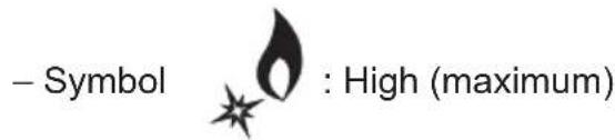
- Symbol : Low (minimum)
■ You can control the temperature by the knob to "High" (maximum) from "Low" "Minimum".
■ To switch off, turn the knob clockwise until you hear the safety click.
■ Note that, if you are using a burner at the minimum setting, you turn the knob clockwise past the maximum setting before reaching the off position.
■ Whenever lighting any of the burners produces an abnormal flame, switch that burner off and relight using the minimum setting.
■ If after relighting the burner, the flame is still abnormal, turn the burner off and contact our Customer Service Centre to obtain the nearest authorized Delonghi Service Agent.
In the case of a mains failure light the burner with a match or lighted taper.
■ Note: When the cooker top is not being used, set the gas knobs to their closed positions and also close the cock valve on the gas bottle or the main gas supply line.
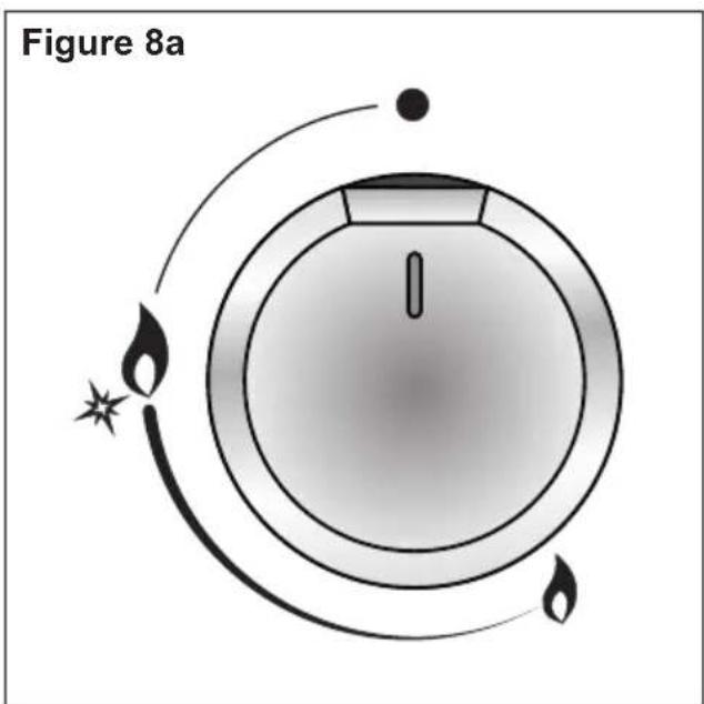
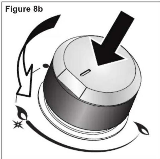
LIGHTING GAS BURNERS FITTED WITH FLAME FAILURE SAFETY DEVICE
In order to light the burner, you must:
- Turn the knob (figs. 8a - 8b) in anti-clockwise direction up to the maximum aperture (symbol “▲”), push in and hold the knob; this will light the gas.
If there is no mains electrical supply, bring a lighted match close to the burner.
- Wait for about ten seconds after the gas burner has been lit before letting go of the knob (valve activation delay).
- Adjust the gas valve to the desired position.
Important
■ If the burner flame should go out, the safety valve will automatically stop the gas flow
■ To re-light the burner, return the knob to closed “●” position (burner off), wait for at least 1 minute and then repeat the lighting procedure.
■ N.B. If your local gas supply makes it difficult to light the burner with the knob set to maximum, set the knob to minimum and repeat the operation.
DUAL BURNER - MODELS DEGHSL90 ONLY
The Dual Burner is a very flexible burner which allows different regulations and optimal cooking.
It is composed by one inner and one outer crown: the inner and outer crown can be used together or separately.
The Dual burner is controlled by two separate knobs (fig. 9):
■ one knob for the inner crown only (“●” symbol identifying the control knob);
■ one knob for the outer crown only ("○" symbol identifying the control knob).
The Dual burner can be used:
■ as a small burner (flame produced only by the inner crown);
■ as a Ultra-rapid burner (flame produced only by the outer crown);
■ as a high-power burner (all flames produced simultaneously by inner and outer crown).

IMPORTANT: After using the dual burner check both the control knobs are in the closed “●” position.
IMPORTANT: After using the dual burner check both the control knobs are in the closed “●” position.
Figure 9
COOKING HINTS FOR GAS HOBS
■ The burner must be chosen according to the diameter of the pans and energy required.
■ The largest can be used for boiling, to seal meat or foods that are cooked quickly, and the smallest for stews and sauces.
■ Always ensure that you use the correct size of saucepan.
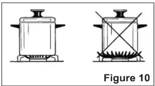
■ For fast boiling, make sure the flame just reaches the edge of the pan. Flames going up the side of the pan means wasted heat and the contents of the pan will take longer to boil.
■ For optimum efficiency use a wok or pan no smaller than 230mm diameter.
■ Saucepans with handles which are excessively heavy, in relationship to the weight of the pan, are safer as they are less likely to tip.
■ Pans which are positioned centrally on burners are more stable than those which are offset.
It is far safer to position the pan handles in such a way that they cannot be accidentally knocked.
■ When deep fat frying:
– Fill the pan only one third full of oil.
- DO NOT cover the pan with a lid and DO NOT leave the pan unattended.
– In the unfortunate event of a fire, leave the pan where it is and turn off all controls.
- Place a damp cloth or correct fitting lid over the pan to smother the flames.
- DO NOT use water on the fire.
- Leave the pan to cool for at least 30 minutes.
WARNING - VERY IMPORTANT NOTICE
During use cooking vessels become hot. Pay special attention not to touch the hot vessels positioned on the cooking hob especially when operating the control knobs.
| DIAMETERS OF PANS WHICH MAY BE USED ON THE BURNERS | ||
| BURNERS MINIMUM MAXIMUM | ||
| Auxiliary 6 cm 14 cm | ||
| Semi-rapid 16 cm 24 cm | ||
| Rapid (models DEGHSL75, DEGHSL90) 24 cm 26 cm | ||
| Triple-ring compact (model DEGHSL60) 26 cm 28 cm | ||
| Triple-ring (model DEGHSL75) | 26 cm 28 cm | |
| Dual (inner crown only) (model DEGHSL90) (*) | 20 cm 24 cm | |
| Dual (outer crown only) (model DEGHSL90) | 26 cm 28 cm | |
| Dual (inner+outer crown) (model DEGHSL90) | 26 cm 28 cm | |
| Wok (**) | - | Max 36 cm |
| do not use pans with concave or convex bases | ||
(*) with small pan adapter: minimum diameter 6 cm
(**) triple-ring compact, triple-ring or dual burner (depending on models) with wok adapter correctly fitted
SMALL PAN ADAPTER - MODEL DEGHSL90 ONLY
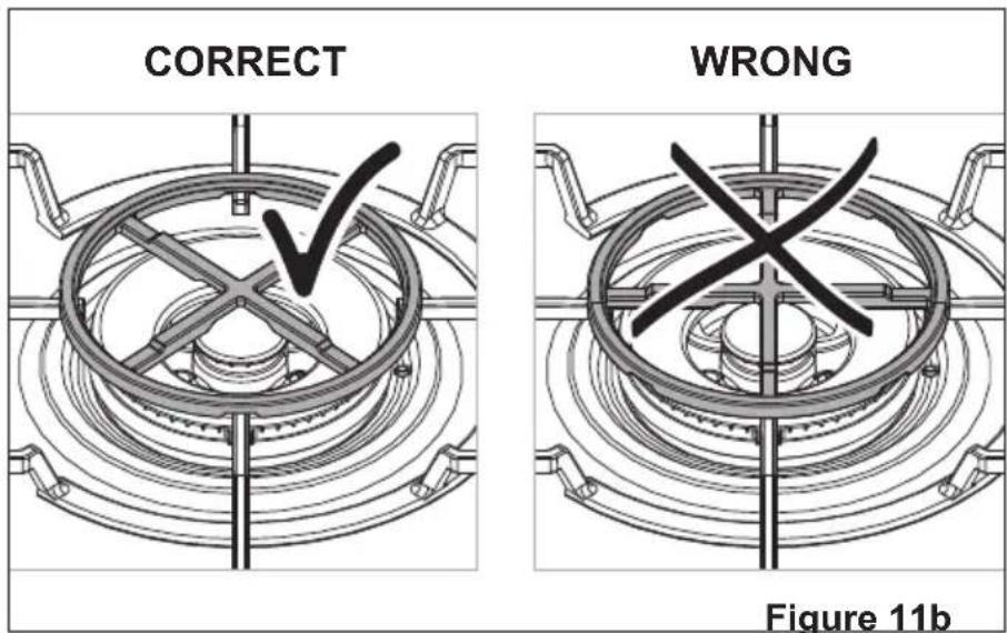
This adapter is to be placed:
■ on top of the Dual burner (used with the inner crown only) when using small diameter pans, in order to prevent them from tipping over.
IMPORTANT:
To avoid any burner malfunction:
■ this adapter MUST be placed correctly (figs. 11a, 11b, 11c);
■ DO NOT USE the outer crown of the Dual burner with the small pan adapter in place;
■ DO NOT USE the inner and outer crown of the Dual burner at the same time with the small pan adapter in place.


WOK STAND
(figs. 12a - 12b, 13a - 13b, 14a - 14b)
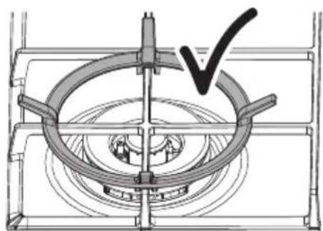
This special grille for woks should be placed over the pan-rest for the triple-ring compact, triple ring or Dual burner (depending on models).
Warning:
■ The flat-bottomed pans are to be placed directly onto the pan-support.
To use the WOK, you must place the wok stand in the CORRECT position as shown.
IMPORTANT:
The special grille for wok pans MUST BE PLACED ONLY over the pan-rest for the triple-ring compact, triple ring or Dual burner (depending on models).
Model: DEGHSL60 (with triple-ring compact burner)
CORRECT

Figure 12a Figure 12b

WRONG

Model: DEGHSL75 (with triple-ring burner)

Figure 13a

Figure 13b
Model: DEGHSL90 (with dual burner)

Figure 14a

Figure 14b
CLEANING and MAINTENANCE
GENERAL ADVICE
■ Before you begin cleaning, you must ensure that the appliance is switched off and disconnected from the electrical power supply.
■ Important: The use of suitable protective clothing/gloves is recommended when handling or cleaning of this appliance.
■ Under no circumstances should any external covers be removed for servicing or maintenance except by suitable qualified personnel.
It is advisable to clean when the appliance is cold and especially when cleaning the enamelled parts.
■ Be very careful that no water penetrates inside the appliance.
■ Avoid leaving alkaline or acidic substances (lemon juice, vinegar, etc.) on the surfaces.
■ Avoid using cleaning products with a chlorine or acidic base.
■ Do not use a steam cleaner because the moisture can get into the appliance thus make it unsafe.
WARNING: When correctly installed, your product meets all safety requirements laid down for this type of product category. However special care should be taken around the underneath of the appliance as this area is not designed or intended to be touched and may contain sharp or rough edges, that may cause injury.
ENAMELLED PARTS
■ All the enamelled parts must be cleaned with a sponge and soapy water only or other non-abrasive products.
■ Dry preferably with a soft cloth.
If acid substances such as lemon juice, tomato conserve, vinegar etc. are left on the enamel for a long time they will etch it, making it opaque.
STAINLESS STEEL SURFACES
■ Stainless steel parts must be rinsed with water and dried with a soft and clean cloth.
■ For persistent dirt, use specific non-abrasive products available commercially or a little hot vinegar.
PAINTED PARTS AND SILKSCREEN PRINTED SURFACES
■ Clean using an appropriate product. Always dry thoroughly.
IMPORTANT: these parts must be cleaned very carefully to avoid scratching and abrasion. You are advised to use a soft cloth and neutral soap.
CAUTION: Do not use abrasive substances or non-neutral detergents as these will irreparably damage the surface.
GAS TAPS
■ Periodic lubrication of the gas taps must be carried out by specialist personnel only.
In the event of operating faults in the gas taps, call the Service Department.
BURNERS
■ These parts can be removed and cleaned with appropriate products.
■ After cleaning, the burners and their flame spreaders must be well dried and correctly replaced.
- Check that the electrode/s "S" (figs. 15a, 15c, 15d, 15e) next to each burner is/are always clean to ensure trouble-free sparking.
- Check that the probe/s "T" (figs. 15a, 15c, 15d, 15e) next to each burner is/are always clean to ensure correct operation of the safety valves.
■ Both the probe and ignition plug must be very carefully cleaned.
■ Note: To avoid damage to the electric ignition do not use it when the burners are not in place.
CORRECT REPLACEMENT OF THE AUXILIARY, SEMI-RAPID AND RAPID BURNER (the rapid burner is available for the models DEGHSL75, DEGHSL90 only)
It is very important to check that the burner flame spreader "F" and the cap "C" have been correctly positioned (see figs. 15a and 15b). Failure to do so can cause serious problems.
■ They shall be level and the flame spreader must not rotate.
CORRECT REPLACEMENT OF THE TRIPLE-RING COMPACT (model DEGHSL60 only), TRIPLE-RING (model DEGHSL75 only) AND DUAL BURNER (model DEGHSL90 only)
It is very important to check that the burner flame spreader "F1", "F2" or "F3" and the caps "A", "B" have been correctly positioned (see figs. 15c, 15d, 15e, 15f, 15g). Failure to do so can cause serious problems.
■ Fit the flame spreader to the housing: the burner ribs must be fitted in their housing as shown by the arrows (see figs. 15c, 15d or 15e).
■ Then position the cap "A" and the ring "B" (see fig. 15f).
■ They shall be level and the flame spreader must not rotate (see fig. 15g).

Figure 15a Figure 15b

TRIPLE-RING COMPACT BURNER
(Model: DEGHSL60)

TRIPLE-RING BURNER (Model:DEGHSL75)

DUAL BURNER
(Model: DEGHSL90)

Figure 15e

Figure 15f Figure 15g

PAN SUPPORTS
■ These parts can be removed and cleaned with appropriate products.
■ After cleaning, they must be well dried and correctly replaced.
It is very important to check that the pan supports have been correctly positioned. Failure to do so can cause serious problems.
■ The prongs of the pan supports must always be centred with the burners (fig. 16a).
■ The raised portion of the pan supports shall NOT face the sides of the cooktop (fig. 16b).
Auxiliary, Semi-rapid & Rapid burner (Rapid for models DEGHSL75 & DEGHSL90 only)

Triple-ring compact burner (model DEGHSL60 only)

Triple-ring burner (model DEGHSL75 only) & Dual burner (model DEGHSL90 only)
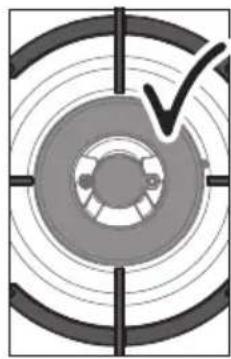

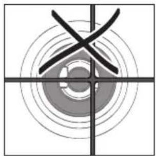
Figure 16a


Figure 16b
SERVICE AND MAINTENANCE
If the ignition spark fails to ignite or does not light the gas, check the following items before calling our Customer Service Centre to obtain the nearest Authorised Delonghi Service Agent:
■ Burner is reassembled and located correctly.
■ Spark electrode and white ceramic are clean and dry.
■ 230 or 240 VAC power supply is connected.
Contact the local gas utility or our Customer Service Centre to obtain the nearest Authorized Delonghi Service Agent.
■ You can smell gas when all burners are turned on.
■ The burners do not remain alight at the minimum marked setting.
■ The burner flame is yellow or emits an unusual odour.
Note that a bi-annual inspection of the appliance by an authorized service agent or your locate gas utility will ensure many years of trouble free operation of your appliance.
Servicing the appliance:
Service may be obtained by contacting our Customer Service Centre to locate the nearest Authorised Delonghi Service Agent.
Servicing shall be carried out only by authorized personnel. The appliance shall not be modified.
LUBRICATION OF THE GAS TAPS
If the gas tap becomes stiff, it is necessary to dismantle it carefully and clean it with petroleum spirit.
Specialist high temperature resistant grease should be used to lubricate the tap before replacing.
These operations must be carried out by an authorized person/service agent.

Descriptions and illustrations in this booklet are given as simply indicative. The manufacturer reserves the right, considering the characteristics of the models described here, at any time and without notice, to make eventual necessary modifications for their construction or for commercial needs.
www.delonghi.com.au www.delonghi.co.nz


- INSTALLATION AND SERVICE INSTRUCTIONS USE AND CARE INSTRUCTIONS
- DEAR CUSTOMER
- PRODUCT LABEL
- IMPORTANT SAFETY PRECAUTIONS AND RECOMMENDATIONS
- INSTALLATION
- CAUTION
- WARNING
- ELECTRICAL REQUIREMENTS
- N.B. THE CONNECTION OF THE APPLIANCE TO EARTH IS MANDATORY
- ELECTRIC DIAGRAM KEY
- DEGHSL75 MODEL ONLY
- CLEARANCES
- IMPORTANT NOTE
- STANDARDS REQUIREMENT
- FASTENING THE COOKTOP
- GAS SUPPLY
- INSTALLATION WITH A FLEXIBLE HOSE ASSEMBLY
- CONVERSION PROCEDURE (TO CONVERT TO NATURAL GAS OR TO ULPG) REPLACING THE INJECTORS
- IMPORTANT
- NOTE
- MINIMUM BURNER SETTING ADJUSTMENT
- LUBRICATING THE GAS TAP
- USE AND CARE
- GAS BURNERS
- CONTROL KNOBS
- NOTES
- USING GAS BURNERS
- LIGHTING GAS BURNERS FITTED WITH FLAME FAILURE SAFETY DEVICE
- DUAL BURNER - MODELS DEGHSL90 ONLY
- COOKING HINTS FOR GAS HOBS
- WARNING - VERY IMPORTANT NOTICE
- SMALL PAN ADAPTER - MODEL DEGHSL90 ONLY
- WOK STAND
- CLEANING AND MAINTENANCE
- GENERAL ADVICE
- ENAMELLED PARTS
- STAINLESS STEEL SURFACES
- PAINTED PARTS AND SILKSCREEN PRINTED SURFACES
- GAS TAPS
- BURNERS
- CORRECT REPLACEMENT OF THE AUXILIARY, SEMI-RAPID AND RAPID BURNER (THE RAPID BURNER IS AVAILABLE FOR THE MODELS DEGHSL75, DEGHSL90 ONLY)
- CORRECT REPLACEMENT OF THE TRIPLE-RING COMPACT (MODEL DEGHSL60 ONLY), TRIPLE-RING (MODEL DEGHSL75 ONLY) AND DUAL BURNER (MODEL DEGHSL90 ONLY)
- PAN SUPPORTS
- SERVICE AND MAINTENANCE
- SERVICING THE APPLIANCE
- LUBRICATION OF THE GAS TAPS
Brand : DELONGHI
Model : DEGHSL90
Category : Cooker