
ZKC6244X - Range hood ZANKER - Free user manual and instructions
Find the device manual for free ZKC6244X ZANKER in PDF.


| Product type | Range hood |
| Brand | ZANKER |
| Model | ZKC6244X |
| Width | 59,8 cm |
| Depth | 45 cm |
| Height (external extraction version) | 62,2 - 115,2 cm |
| Height (recirculation version) | 69,9 - 115,2 cm |
| Total nominal power | 160 W |
| Motor power | 120 W |
| Lighting | 2 bulbs × 20 W (G4) |
| Cable length | 150 cm |
| Voltage | 220 - 240 V |
| Use version | External extraction or recirculation (optional charcoal filter) |
| Exhaust duct diameter | 150 mm (reducible to 120 mm with sleeve) |
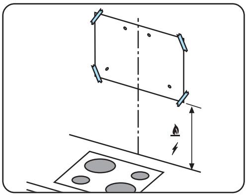
| Minimum safety distance (electric cooking) | 50 cm |
| Minimum safety distance (gas or mixed cooking) | 65 cm |
| Metal grease filter | Dishwasher safe, clean every 4 weeks |
| Charcoal filter (optional) | Type 20, dishwasher safe + oven drying, replace every 3 years |
| Motor speed | 3 adjustable speeds |
| Included mounting material | TORX bits, reduction sleeve, deflector, chimney bracket, wall plugs, screws, washers |
Frequently Asked Questions - ZKC6244X ZANKER
User questions about ZKC6244X ZANKER
0 question about this device. Answer the ones you know or ask your own.
Ask a new question about this device
Download the instructions for your Range hood in PDF format for free! Find your manual ZKC6244X - ZANKER and take your electronic device back in hand. On this page are published all the documents necessary for the use of your device. ZKC6244X by ZANKER.
USER MANUAL ZKC6244X ZANKER
natural_image
Isometric line drawing of a metal shelf with a gridded top (no text or symbols)ZKC 9244
ZKC 6244
natural_image
Diagram showing a downward arrow and a small object on a horizontal line, no text or symbols presentnatural_image
Illustration of a hand holding a small object with a magnifying glass above it, no text or symbols present.natural_image
Technical line drawing of a mechanical device with a rotating knob and directional arrow (no text or symbols)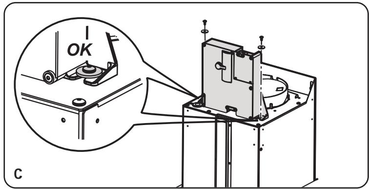
natural_image
Technical line drawing of a mechanical assembly with an inset showing a close-up view of a component labeled 'OK' (no text or symbols beyond the label)Befestigung
natural_image
Diagram showing a structural frame with a vertical dimension and a lightning bolt symbol, no text or labels present.natural_image
Diagram showing a hand holding a pen with coordinate axes and arrows, no text or symbols present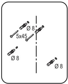
natural_image
Technical line drawing of an electrical switch mechanism with no visible text or symbolsnatural_image
Diagram of a mechanical assembly with a coiled spring and base device (no text or symbols)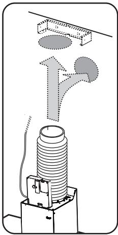
natural_image
Diagram of a mechanical or electrical component with a coiled spring and upward flow arrow (no text or symbols)natural_image
Technical diagram of a mechanical assembly with a cylindrical component and mounting bracket (no text or symbols)natural_image
Technical line drawing of a mechanical device with a component and directional arrows (no text or symbols)
natural_image
Isometric line drawing of a three-tiered cylindrical structure with labeled components (no text or symbols)natural_image
Diagram showing a downward arrow and a small object on a horizontal line, no text or symbols presentnatural_image
Illustration of a hand holding a small object with a magnifying glass above it, no text or symbols present.natural_image
Technical line drawing of a mechanical device with a rotating knob and directional arrow (no text or symbols)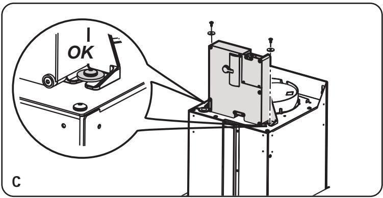
natural_image
Technical line drawing of a mechanical assembly with an inset showing a close-up view of a component labeled 'OK' (no text or symbols beyond the label)Installatie
natural_image
Diagram showing a structural frame with vertical and horizontal dimensions, and a patterned surface with circular holes (no text or symbols)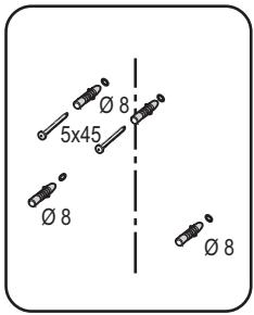
natural_image
Technical line drawing of an electrical device with wiring and directional arrows indicating motion (no text or symbols)natural_image
Diagram of a mechanical device with a cylindrical component and a base unit, showing internal structure without any text or symbols.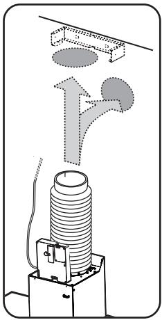
natural_image
Diagram of a mechanical or electrical component with internal structure and airflow direction arrows (no text or symbols)natural_image
Technical diagram of a mechanical assembly with a cylindrical component and mounting bracket (no text or symbols)natural_image
Technical line drawing of a mechanical device with a cylindrical component and a bracket, showing motion indicators (no text or symbols)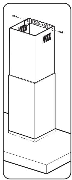
- Monteer het/de vetfilter/s.
natural_image
Diagram showing a downward arrow and a small object on a horizontal line, no text or symbols presentnatural_image
Illustration of a hand holding a small device with a magnifying glass above it, no text or symbols present.natural_image
Technical line drawing of a mechanical device with a rotating knob and directional arrow (no text or symbols)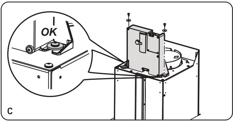
natural_image
Technical line drawing of a mechanical assembly with an inset showing a close-up view of a component labeled 'OK' (no text or symbols beyond the label)Installation de la hotte
natural_image
Diagram showing a structural frame with vertical dimension and a lightning bolt symbol, no text or labels presentnatural_image
Hand holding a pen to coordinate axes with arrows, no text or symbols present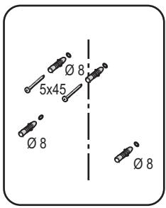
natural_image
Technical line drawing of an electrical device with wiring and motion arrows indicating motion (no text or symbols)natural_image
Diagram of a mechanical assembly with a coiled spring and base device (no text or symbols)natural_image
Diagram of a mechanical or electrical component with a coiled spring and upward flow indicator (no text or symbols)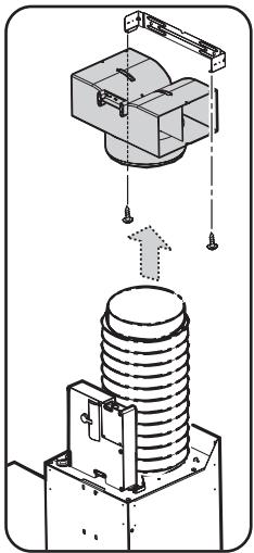
natural_image
Technical diagram of a mechanical assembly with a cylindrical component and mounting bracket (no text or symbols)natural_image
Technical line drawing of a mechanical device with an open lid and internal component, showing motion indicators (no text or symbols)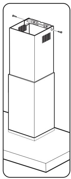
natural_image
Isometric line drawing of a three-tiered cylindrical structure with labeled components (no text or symbols)- Fixer la grille d'aspiration.
Welcome to the world of Electrolux
Thank you for choosing a first class product from Electrolux, which hopefully will provide you with lots of pleasure in the future. The Electrolux ambition is to offer a wide variety of quality products that make your life more comfortable. You find some examples on the cover in this manual. Please take a few minutes to study this manual so that you can take advantage of the benefits of your new machine. We promise that it will provide a superior User Experience delivering Ease-of-Mind.
Good luck!
Contents
Safety warnings 53
Description of the Appliance 55
Control Panel 57
Maintenance and Care 58
Cleaning the hood 60
Special accessories 61
Technical Details 61
Electrical connection 62
Installation 64

Safety warnings
- When used as an extractor unit, the hood must be fitted with a hose having preferably the same diameter as the outlet hole. Should there already be a pipe of diameter 125 mm that ducts to the outside through the walls or roof, it is possible to use the 150/125 mm reduction flange provided. In this case the hood will be slightly noisier.
Attention: The hose is not supplied and must be purchased separately. - The minimum distance between the supporting surface for the cooking vessels on the hob and the lowest part of the range hood must be not less than 50cm from electric cookers and 65cm from gas or mixed cookers.
If the instructions for installation for the gas hob specify a greater distance, this must be adhered to. - Before any cleaning or maintenance operation, disconnect the hood from the mains by removing the plug or disconnecting the home mains switch.
- The appliance is not intended for use by children or persons with impaired physical, sensorial or mental faculties, or if lacking in experience or know-how, unless they are under supervision or have been trained in the use of the appliance by a person responsible for their safety.
- Children should be monitored to ensure that they do not play with the appliance.
- Never use the hood without effectively mounted grating.!
- The hood must NEVER be used as a support surface unless specifically indicated.
- The premises must be sufficiently ventilated, when the kitchen hood is used together with
other gas combustion devices or other fuels.
- The suctioned air must not be conveyed into a conduit used for the disposal of the fumes generated by appliances that combust gases or other fuels.
- The flaming of foods beneath the hood itself is severely prohibited.
- The use of exposed flames is detrimental to the filters and may cause a fire risk, and must therefore be avoided in all circumstances.
- Any frying must be done with care in order to make sure that the oil does not overheat and burst into flames.
- As regards the technical and safety measures to be adopted for fume discharging it is important to closely follow the relations provided by the competent authorities.
- The hood must be regularly cleaned on both the inside and outside (AT LEAST ONCE A MONTH, it is in any event necessary to proceed in accordance with the maintenance instructions provided in this manual)..
- Failure to follow the instructions as concerns hood and filter cleaning will lead to the risk of fires.
- Do not use or leave the hood without the lamp correctly mounted because of the possible risk of electric shocks.
- We decline any responsibility for any problems, damage or fires caused to the appliance as the result of the non-observance of the instructions included in this manual.
This appliance is marked according to the European directive 2002/96/EC on Waste Electrical and Electronic Equipment (WEEE). By ensuring this product is disposed of correctly, you will help prevent potential negative consequences for the environment and human health, which could otherwise be caused by inappropriate waste handling of this product.

The symbol ■ on the product, or on the documents accompanying the product, indicates that this appliance may not be treated as household waste. Instead it shall be handed over to the applicable collection point for the recycling of electrical and electronic equipment. Disposal must be carried out in accordance with local environmental regulations for waste disposal.
For more detailed information about treatment, recovery and recycling of this product, please contact your local city office, your household waste disposal service or the shop where you purchased the product.
Description of the Appliance
- The cooker hood is designed to extract unpleasant odours from the kitchen, it will not extract steam.
- The hood is supplied as an extractor unit and can also be used with a recirculation mode by fitting a charcoal filter.
- You will need an original charcoal filter for the recirculation mode. (See Special Accessories).
Extraction mode
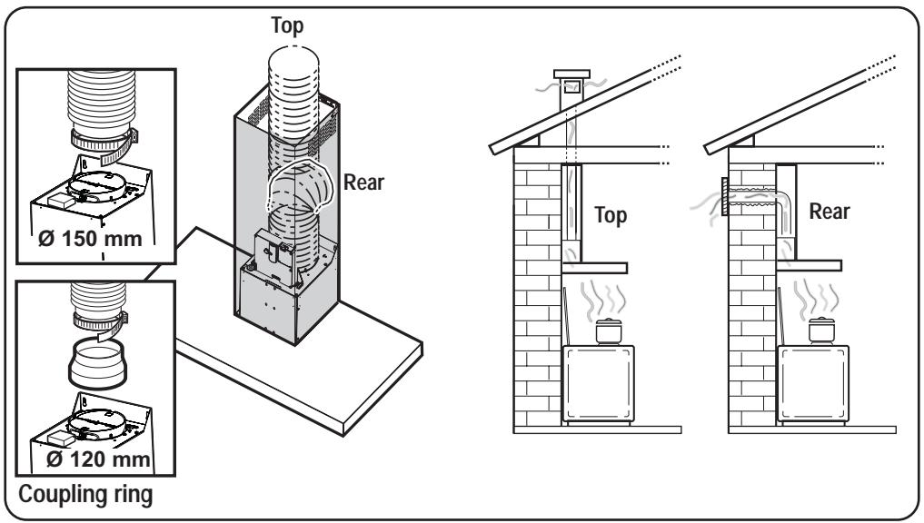
- In this mode fumes are extracted to the outside via a hose connected to the coupling ring.
- In order to obtain the best performance the hose should have a diameter equal to the outlet hole.
Recirculation mode

- The air is filtered through a charcoal filter and returned to the kitchen.
- You will need an original charcoal filter for the recirculation mode. (See Special Accessories).
Control Panel
- Best results are obtained by using a low speed for normal conditions and a high speed when odours are more concentrated.
Turn the hood on a few minutes before you start cooking.
The hood should be left on after cooking for about 15 minutes or until all the odours have disappeared.
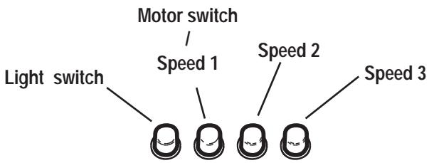
The control switches are located on the unit's front panel:
flowchart
graph TD
    A["Light switch"] --> B["Terminal"]
    C["Motor switch / Speed 1"] --> D["Terminal 1"]
    E["Motor switch / Speed 2"] --> F["Terminal 2"]
    G["Motor switch / Speed 3"] --> H["Terminal 3"]
- the light switch switches the hood lamp on and off
• the motor switch switches the motor off
Speed 1: Speed 1 push-button
• Speed 2: Speed 2 push-button
• Speed 3: Speed 3 push-button
Maintenance and Care
- Warning! Before performing any maintenance operation, isolate the hood from the electrical supply by switching off at the connector and removing the connector fuse. Or if the appliance has been connected through a plug and socket, then the plug must be removed from the socket.
Metal grease filter
- The purpose of the grease filters is to absorb grease particles which form during cooking and it must always be used, either in the external extraction or internal re-circulation function.
Attention: the metal grease filters must be removed and washed, either by hand or in the dishwasher, every four weeks.
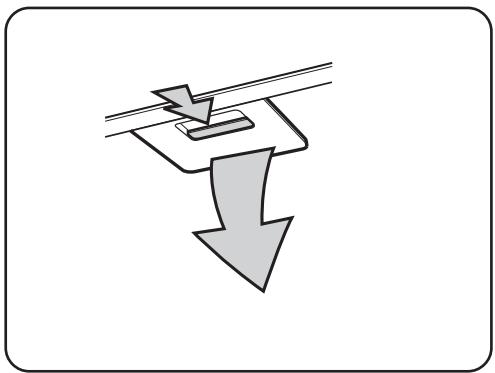
Removing the metal grease filter
natural_image
Diagram showing a downward arrow with a small object above it, no text or symbols present- Use the spring handle and remove the filter downward.
Hand washing
Soak grease filters for about one hour in hot water with a grease-loosening cleaner, then rinse off thoroughly with hot water. Repeat the process if necessary. Refit the grease filters when they are dry.
Dishwasher
Place grease filters in the dishwasher. Select most powerful washing programme and highest temperature, at least 65°C. Repeat the process. Refit the grease filters when they are dry.
- Attention! When washing the metal grease filter in the dishwasher a slight discolouration of the filter can occur, this does not have any impact on its performance.
- Clean the inner housing using a hand hot solution only(never use caustic detergents, abrasive powders or brushes).
Charcoal filter
- The charcoal filter should only be used if you want to use the hood in recirculation mode.
• To do this you will need an original charcoal filter (available from your local Service Force Centre). - Cleaning/replacing the charcoal filter
Unlike other charcoal filters, the LONGLIFE charcoal filter can be cleaned and reactivated.
With normal use the filter should be cleaned every second month (when using the hood 2.5 hours per day, on avarage). The best way to clean the filter is in the dishwasher. Use normal detergent and choose the highest temperature (65°C). Wash the filter separately so that no food parts gets stuck on the filter and later causes bad odours. To reactivate the charcoal, the filter should be dried in an oven for 10 minutes with a maximum temperature of 100°C.
After approximately three years of use, the charcoal filter should be replaced with a new one, as the odour reduction capacity will be reduced.
- Fitting
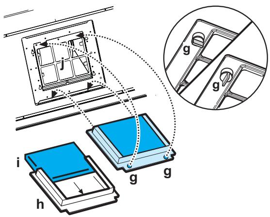
Remove the grease filters.
Remove the frame i which supports the filter h by turning 90° the two knobs g.
Insert the charcoal filter inside the frame and put all parts back in their place.
Refit the grease filters.
• To remove proceed in the reverse order.
- Always specify the hood model code number and serial number when ordering replacement filters. This information is shown on the rating plate located on the inside of the unit.
- The charcoal filter can be ordered from your local Service Force Centre.

Warning
- Failure to observe the instructions on cleaning the unit and changing the filters will cause a fire hazard. You are therefore strongly recommended to follow these instructions.
- The manufacturer declines all responsibility for any damage to the motor or any fire damage linked to inappropriate maintenance or failure to observe the above safety recommendations.
Changing the light bulb(s)
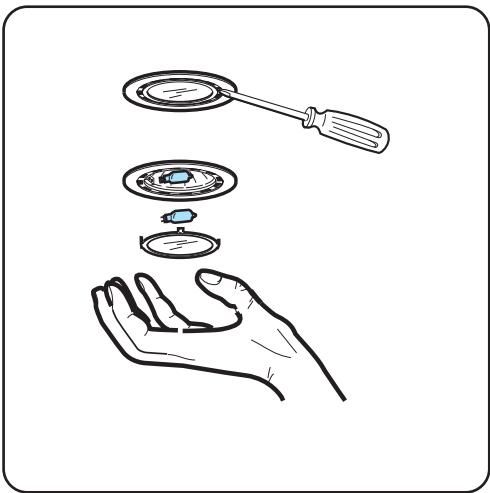
- Disconnect the cooker hood from the mains supply.
- Prior to touching the light bulbs ensure they are cooled down.
natural_image
Illustration of a hand holding a small object with a magnifying glass above it, no text or symbols present.- Extract the lamp cover by using a small flat screwdriver or similar tool as a lever.
- Replace the old bulb with a new one of the same type.
- Refit the lamp cover.
- If the light does not come on, make sure the bulb has been inserted in correctly before contacting your local Service Force Centre.
Cleaning the hood
- Clean the outside of the hood using a damp cloth and a solution of water and mild washing up liquid.
- Never use corrosive, abrasive or flammable cleaning products or products containing bleach.
- Never insert pointed objects in the motor's protective grid.
- Only ever clean the switch panel and filter grill using a damp cloth and mild washing up liquid.
- Clean all the plastic parts with a soft cloth soaked in warm water and neutral soap.
- It is extremely important to clean the unit and change the filters at the recommended intervals. Failure to do so will cause grease deposits to build up that could constitute a fire hazard.
Technical Details
| ZKC 6244 | ZKC 9244 | |
| Dimensions (in cm): | ||
| Height (Extract. mode): | 62,2-115,2 | 62,2-115,2 |
| Height (Recirc. mode): | 69,9-115,2 | 69,9-115,2 |
| Width: | 59,8 | 89,8 |
| Depth: | 45 | 45 |
| Max. absorb. power: | 160 W | 160 W |
| Motor: | 120 W | 120 W |
| Lighting: | 2 x 20 W (G4) | 2 x 20 W (G4) |
| Length of the cable: | 150 cm | 150 cm |
| Electrical connection: | 220-240 V | 220-240 V |
| Fuse rating: | 5At | 5At |
Mounting accessories included
| 2 screwdriver bits (for TORX screws). |
| 1 deflector, |
| 1 reduction flange ∅ 125-120 mm, |
| 1 chimney support, |
| 6 wood-screws 5 x 45 mm (for wall mounting), |
| 6 Wall dowels ∅ 8 mm (for wall mounting), |
| 2 washers |
| 2 screws 2,9 x 6,5 (2 to fix the upper chimney) |
| 2 metal screws 3 x 9 (to fix the deflector). |
Electrical connection
Safety warnings for the electrician
The mains power supply must correspond to the rating indicated on the plate situated inside the hood. If provided with a plug connect the hood to a socket in compliance with current regulations and positioned in an accessible area. If it not fitted with a plug (direct mains connection) or if the plug is not located in an accessible area apply a bi-polar switch in accordance with standards which assures the complete disconnection of the mains under conditions relating to over-current category III, in accordance with installation instructions.
IMPORTANT: Before re-connecting the hood circuit to the mains supply and checking the efficient function, always check that the mains cable is correctly assembled.
Before beginning installation
- In addition check whether near the installation area of the hood (in the area accessible also with the hood mounted) an electric connection to the mains is available and if it is possible to connect a fumes discharge device to the outside (Extraction mode only).
- Warning! Do not connect the appliance to the mains until the installation is fully complete.
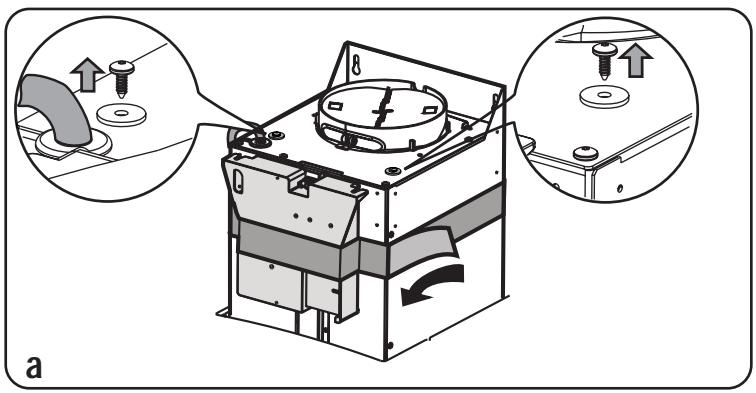
• Install the electronic box with 2 screws (a-b-c).
natural_image
Technical illustration of a mechanical device with two views of the component, showing internal components and assembly (no text or symbols present)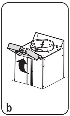
natural_image
Technical line drawing of a mechanical device with a rotating knob and directional arrow (no text or symbols)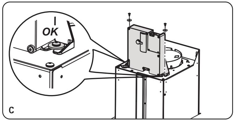
natural_image
Technical line drawing of a mechanical assembly with an inset showing a close-up view of a component labeled 'OK' (no text or symbols beyond the label)Installation
- Remove the grease filters.
- Drawing a line on the wall with a pencil up to the ceiling, corresponding to the centre line, will make the installation operations easier.
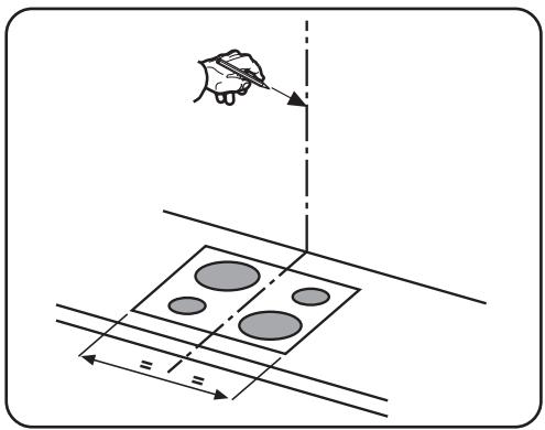
- Apply the perforation diagram to the wall: the vertical centre line printed on the perforation diagram should correspond to the centre line drawn on the wall. In addition, the lower edge of the perforation diagram corresponds to the lower edge of the hood.
natural_image
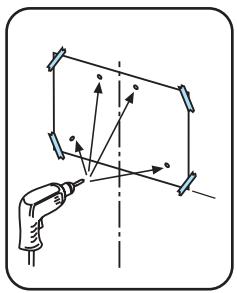
Diagram showing a structural frame with dimension lines and a magnified view of circular components (no text or symbols)- Make holes as indicated on the template, insert the wall dowels and screw 2 screws into the upper holes, leaving a space of about 1 cm between the head of the screw and the wall..
natural_image
Hand holding a pen to coordinate axes with arrows, no text or symbols present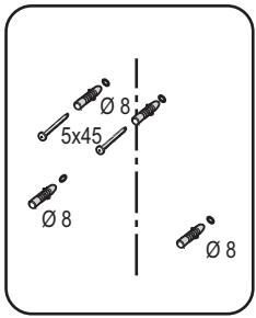
Note: Always make the holes indicated on the template. The upper 2 are for hooking the hood up while the lower holes (generally 2 lateral) are for the definitive and safety fixing.
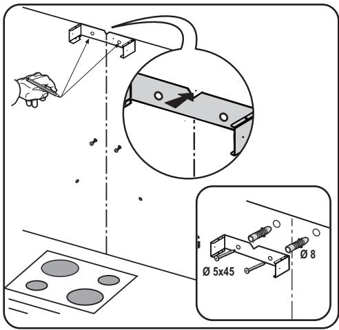
- Apply flues support bracket to the wall touching the ceiling. Use the flues support bracket as a perforation diagram (the small slot in the support must coincide with the line previously drawn on the wall, if present), and mark two holes with a pencil. Make the holes and insert 2 dowels.
- Fix the flues support bracket to the wall with 2 screws.
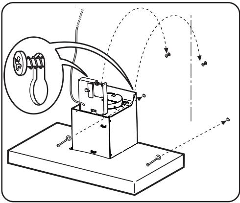
- Hang the hood to the 2 upper screws.
- Introduce and screw the screws (and washers) up into the holes for the definitive fixing (COMPULSORY!!). Then, having checked the setting of the hood, TIGHTEN ALL THE upper and lower SCREWS.
natural_image
Technical line drawing of an electrical device with wiring and components, no visible text or symbolsNote: the lower fixing points are visible removing the grease filters and they are at the sides of the hood
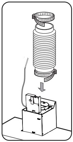
- Connect a tube (tube and bands for fixing not supplied, to be purchased) for discharging the fumes to the connection ring placed over the aspiration motor unit.
The other end of the tube should be connected to a device for expelling fumes on the outside of the hood in the aspiration version.
natural_image
Diagram of a mechanical device with a coiled spring and base unit, showing internal components and wiring (no text or symbols)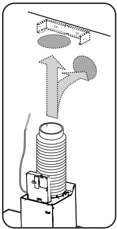
natural_image
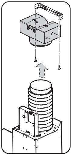
Diagram of a mechanical device with a coiled spring and directional arrows indicating motion (no text or symbols)If you want to use the filtering version, fix deflector to flues support bracket and connect the other end of the tube to the connection ring placed on deflector.
natural_image
Technical diagram of a mechanical assembly with a cylindrical component and mounting bracket (no text or symbols)- Connect the electricity.
- Slide the lower section of the flue down to cover the aspiration set until inserting it completely into the apposite housing over the hood.
- Raise the upper flue and fix it above with 2 screws to flues support bracket

natural_image
Technical line drawing of a mechanical device with a component and directional arrows (no text or symbols)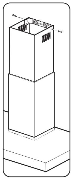
natural_image
Isometric line drawing of a three-tiered industrial or structural component with no visible text or symbols- Refit the grease filter.
Garantie/Kundendienst
Deutschland
ELECTROLUX HAUSGERÄTE GMBH
ADRESSE
HERZIGGASSE 9
A-1230 WIEN
VERTRIEB TELEFON
(01) 866 40-200
VERTRIEB TELEFAX
(01) 866 40-250
KUNDENDIENST TELEFON
(01) 866 40-330
KUNDENDIENST TELEFAX
(01) 866 40-300
WIEN FN 98903 x
DVR: 0595411
ARA LIZENZ NR. 2702
UID: ATU 14758207
Guarantee/Customer Service
Standard guarantee conditions
We, Electrolux, undertake that if within 12 months of the date of the purchase this Electrolux appliance or any part thereof is proved to be defective by reason only of faulty workmanship or materials, we will, at our option repair or replace the same FREE OF CHARGE for labour, materials or carriage on condition that:
- The appliance has been correctly installed and used only on the electricity supply stated on the rating plate.
- The appliance has been used for normal domestic purposes only, and in accordance with the manufacturer's instructions.
- The appliance has not been serviced, maintained, repaired, taken apart or tampered with by any person not authorised by us.
- Electrolux Service Force Centre must undertake all service work under this guarantee.
- Any appliance or defective part replaced shall become the Company's property.
- This guarantee is in addition to your statutory and other legal rights.
Exclusions
- Damage or calls resulting from transportation, improper use or neglect, the replacement of any light bulbs or removable parts of glass or plastic.
-
Costs incurred for calls to put right an appliance which is improperly installed or calls to appliances outside the United Kingdom.
-
Appliances found to be in use within a commercial environment, plus those which are subject to rental agreements.
- Products of Electrolux manufacturer that are not marketed by Electrolux
Service and Spare Parts
In the event of your appliance requiring service, or if you wish to purchase spare parts, please contact your local Service Force Centre by telephoning
0870 5 929 929
Your telephone call will be automatically routed to the Service Force Centre covering your postcode area.
For the address of your local Service Force Centre and further information about Service Force, please visit the website at
www.serviceforce.co.uk
Before calling out an engineer, please ensure you have read the details under the heading “Something not working” When you contact the Service Force Centre you will need to give the following details:
- Your name, address and postcode.
- Your telephone number.
- Clear concise details of the fault.
- The model and Serial number of the appliance (found on the rating plate).
- The purchase date.
Please note a valid purchase receipt or guarantee documentation is required for in guarantee service calls.
Customer Care
For general enquiries concerning your Electrolux appliance, or for further information on Electrolux products please contact our Customer Care Department by letter or telephone at the address below or visit our website at www.electrolux.co.uk
Customer Care Department
Electrolux Major Appliances
Addington Way
Luton
Bedfordshire
LU4 9QQ
Tel: 08705 950 950 (*)
(*) Calls may be recorded for training purposes
European Guarantee
This appliance is guaranteed by Electrolux in each of the countries listed at the back of this user manual, for the period specified in the appliance guarantee or otherwise by law. If you move from one of these countries to another of the countries listed below the appliance guarantee will move with you subject to the following qualifications:-
- The appliance guarantee starts from the date you first purchased the appliance which will be evidenced by production of a valid purchase document issued by the seller of the
appliance.
- The appliance guarantee is for the same period and to the same extent for labour and parts as exists in your new country of residence for this particular model or range of appliances.
- The appliance guarantee is personal to the original purchaser of the appliance and cannot be transferred to another user.
- The appliance is installed and used in accordance with instructions issued by Electrolux and is only used within the home, i.e. is not used for commercial purposes.
- The appliance is installed in accordance with all relevant regulations in force within your new country of residence.
The provisions of this European Guarantee do not affect any of the rights granted to you by law.
| Albania | +35 5 4 261 450 | Rr. Pjeter Bogdani Nr. 7 Tirane |
| Belgique/België/ Belgien | +32 2 363 04 44 | Bergensesteenweg 719, 1502 Lembeek |
| Èeská republika | +420 2 61 12 61 12 | Budijovická 3, Praha 4, 140 21 |
| Danmark | +45 70 11 74 00 | Sjællandsgade 2, 7000 Fredericia |
| Deutschland | +49 1803 22 66 22 | Muggenhofer Str. 135, 90429 Nürnberg |
| Eesti | +37 2 66 50 030 | Mustamäe tee 24, 10621 Tallinn |
| España | +34 902 11 63 88 | Carretera M-300, Km. 29,900 Alcalá de Henares Madrid |
| France | www.electrolux.fr | |
| Great Britain | +44 8705 929 929 | Addington Way, Luton, Bedfordshire LU4 9QQ |
| Hellas | +30 23 10 56 19 70 | 4 Limnou Str., 54627 Thessaloniki |
| Hrvatska | +385 1 63 23 338 | Slavonska avenija 3, 10000 Zagreb |
| Ireland | +353 1 40 90 753 | Long Mile Road Dublin 12 |
| Italia | +39 (0) 434 558500 | C.so Lino Zanussi, 26 - 33080 Porcia (PN) |
| Latvija | +37 17 84 59 34 | Kr. Barona iela 130/2, LV-1012, Riga |
| Lietuva | +370 5 2780609 | Verkiu 29, LT-09108 Vilnius |
| Luxembourg | +35 2 42 43 13 01 | Rue de Bitbourg, 7, L-1273 Hamm |
| Magyarország | +36 1 252 1773 | H-1142 Budapest XIV, Erzsébet királyné útja 87 |
| Nederland | +31 17 24 68 300 | Vennootsweg 1, 2404 CG – Alphen aan den Rijn |
| Norge | +47 81 5 30 222 | Risløkkvn. 2 , 0508 Oslo |
| Österreich | +43 18 66 400 | Herziggasse 9, 1230 Wien |
| Polska | +48 22 43 47 300 | ul. Kolejowa 5/7, Warsaw |
| Portugal | +35 12 14 40 39 39 | Quinta da Fonte - Edificio Gonçalves Zarco - Q 35 2774 - 518 Paço de Arcos |
| Romania | +40 21 451 20 30 | Str. Garii Progresului 2, S4, 040671 RO |
| Schweiz/Suisse/ Svizzera | +41 62 88 99 111 | Industriestrasse 10, CH-5506 Mägenwil |
| [XOY6] | [SK26] | [ЭФНА] |
| Slovenija | +38 61 24 25 731 | Tr•aška 132, 1000 Ljubljana |
| Slovensko | +421 2 43 33 43 22 | Electrolux Slovakia s.r.o., Electrolux Domáce spotrebiève SK, Seberíniho 1, 821 03 Bratislava |
| Suomi | www.electrolux.fi | |
| Sverige | +46 (0)771 76 76 76 | Electrolux Service, S:t Göransgatan 143, S-105 45 Stockholm |
| Türkiye | +90 21 22 93 10 25 | Tarlabaşı caddesi no : 35 Taksim Istanbul |
| Россия | +7 095 9377837 | 129090 Москва, Олимпийский проспект, 16, БЦ „Олимпик“ |


[Non-Text]





















www.electrolux.com
- Befestigung
- Installatie
- Installation de la hotte
- Welcome to the world of Electrolux
- Contents
- Safety warnings
- Description of the Appliance
- Extraction mode
- Recirculation mode
- Control Panel
- Maintenance and Care
- Metal grease filter
- Hand washing
- Dishwasher
- Charcoal filter
- - Fitting
- Warning
- Changing the light bulb(s)
- Cleaning the hood
- Electrical connection
- Safety warnings for the electrician
- Before beginning installation
- Installation
- Garantie/Kundendienst
- Deutschland
- ELECTROLUX HAUSGERÄTE GMBH
- Guarantee/Customer Service
- Standard guarantee conditions
- Exclusions
- Service and Spare Parts
- 5 929 929
- www.serviceforce.co.uk
- Customer Care
- European Guarantee
Brand : ZANKER
Model : ZKC6244X
Category : Range hood