
DIS-F200G-10PS-E - Uncategorized D-LINK - Free user manual and instructions
Find the device manual for free DIS-F200G-10PS-E D-LINK in PDF.


| Product Type | Ethernet Switch |
| Model Number | DIS-F200G-10PS-E |
| Brand | D-Link |
| Ports | 10 Gigabit Ethernet ports (8 PoE+ and 2 SFP uplinks) |
| PoE Budget | 120W total PoE power budget |
| PoE Standard | IEEE 802.3af/at |
| Switching Capacity | 20 Gbps |
| MAC Address Table | 16K entries |
| Mounting | DIN-rail or wall-mount |
| Power Input | DC 48V |
| Power Consumption | 15W (without PoE load) |
| Operating Temperature | -40°C to 75°C |
| Dimensions (LxWxH) | 160 x 120 x 50 mm |
| Weight | 1.1 kg |
| Safety Certifications | CE, FCC, UL |
| Management | Web GUI, SNMP, CLI |
| VLAN Support | IEEE 802.1Q VLAN |
| Quality of Service | QoS with 8 priority queues |
| Maintenance | Wipe with dry cloth only |
| Cleaning | Avoid liquids and sprays |
| Security | Use strong passwords and update firmware regularly |
| Spare Parts | No user-serviceable parts |
| Repairability | Contact authorized D-Link service center |
| Package Contents | Switch, mounting kit, quick install guide |
Frequently Asked Questions - DIS-F200G-10PS-E D-LINK
User questions about DIS-F200G-10PS-E D-LINK
0 question about this device. Answer the ones you know or ask your own.
Ask a new question about this device
Download the instructions for your Uncategorized in PDF format for free! Find your manual DIS-F200G-10PS-E - D-LINK and take your electronic device back in hand. On this page are published all the documents necessary for the use of your device. DIS-F200G-10PS-E by D-LINK.
USER MANUAL DIS-F200G-10PS-E D-LINK
Web UI Reference Guide
Product Model: DIS-F200G Series
Industrial Gigabit Smart Managed PoE+ Switch
Version 1.00

Table of Contents
Table of Contents
CHAPTER 1: OVERVIEW ...... 6
1.1 TARGET AUDIENCE ....6
1.2 BOOK CONVENTION....6
CHAPTER 2 PRODUCT INTRODUCTION .... 7
2.1 PRODUCT INTRODUCTION....7
2.2 FRONT PANEL 8
2.3 BACK PANEL....9
2.4 INTERFACE FUNCTION LIST....11
CHAPTER 3: MANAGING SWITCHES ...... 14
3.1 WEB LOGIN .... 14
3.2 WEB INTERFACE COMPOSITION....15
3.2.1 GLOBAL INFORMATION....15
3.2.2 TRAFFIC STATISTICS ....16
3.3 LOG INFORMATION....16
3.3.1 LOG LIST....17
3.3.2 EXPORT LOG FILE 18
CHAPTER 4: PORT MANAGEMENT .... 19
4.1 PORT CONFIGURATION....19
4.2 PORT ISOLATION 20
4.3 PORT MIRRORING ....20
4.4 PORT SPEED LIMIT 21
4.5 STORM CONTROL....22
4.6 PORT ENERGY SAVING 23
CHAPTER 5: POE MANAGEMENT ...... 25
5.1 PORT POE MANAGEMENT 25
5.2 DEVICE POWER SUPPLY....26
5.3 TIMING POWER SUPPLY CONFIGURATION ......26
5.3.1 TIME PERIOD CONFIGURATION ......26
5.3.2 TIMING POWER SUPPLY CONFIGURATION ......27
5.4 INTELLIGENT POWER SUPPLY CONFIGURATION....28
CHAPTER 6: LAYER 2 MANAGEMENT....29
6.1 MAC ADDRESS TABLE 29
6.2 VLAN CONFIGURATION 31
6.2.1 VLAN STATE....32
6.2.2 VLAN CONFIGURATION ....32
8.5 LLDP CONFIGURATION....107
8.5.1 GLOBAL CONFIGURATION 110
8.5.2 PORT CONFIGURATION ....111
8.5.3 LLDP PORT CONFIGURATION....111
8.6 NTP CONFIGURATION....111
8.6.1 NTP GLOBAL CONFIGURATION....111
8.6.2 NTP SERVER CONFIGURATION....112
8.7 ANTI-ATTACK 113
CHAPTER 9: SYSTEM MANAGEMENT .... 114
9.1 USER SETTINGS....114
9.2 NETWORK SETTINGS ....114
9.2.1 IPv4 CONFIGURATION....115
9.2.2 IPv6 CONFIGURATION....115
9.3 ALARM CONFIGURATION....116
9.4 SERVICE CONFIGURATION ....117
9.4.1 TELNET SERVICE ....117
9.4.2 SSH SERVICE 117
9.4.3 HTTP SERVICE....118
9.5 CONFIGURATION MANAGEMENT....119
9.5.1 RESET CONFIGURATION 119
9.5.2 UPLOAD CONFIGURATION ....120
9.5.3 DOWNLOAD CONFIGURATION 120
9.6 FIRMWARE UPGRADE....120
9.7 DIAGNOSTIC TEST 121
9.7.1 PING DETECTION 121
9.7.2 TRACERT TEST....122
9.7.3 NETWORK CABLE DETECTION 123
9.8 RESTART THE SYSTEM....124
Chapter 1: Overview
This manual is intended to help you with initial installation and configuration of the switch. The manual includes a description of the switch performance characteristics and a detailed description of the configuration options of the switch. Please read this manual carefully before using the switch.
1.1 Target audience
This manual is intended for installers and system administrators who are responsible for installing, configuring, or maintaining the network. This manual assumes that you understand the transport and management protocols used on Ethernet networks.
This manual also assumes that you are familiar with the terminology, theoretical principles, practical skills, and specific expertise of network devices, protocols, and interfaces related to networking. You must also have a working experience with a graphical user interface, a command line interface, a simple network management protocol and a web browser.
1.2 Book convention
In this manual, the terms “switch” and “this product” mentioned in the article refer to the DIS-F200G-Series Industrial Smart Managed network switch unless otherwise specified.
The text that appears in bold font indicates the name of each function of the switch, such as the port management page. The "double quote" text that appears in the text indicates the noun that appears on the configuration page, such as "IP address". The special icons used in this manual are as follows.
| Icons | Instructions |
 Statement Statement | Description of the operation content, with necessary additions and explanations |
 Note Note | Reminder about things to be aware of during operation. Improper operation may result in data loss or equipment damage. |
Chapter 2: Product Introduction
2.1 Product Introduction
The DIS-F200G Series Gigabit Industrial Smart Managed PoE+ Switches are equipped with 4 (DIS-F200G-6PS-E) and 8 (DIS-F200G-10PS-E) PoE+ capable 10/100/1000BASE-T ports and 2 SFP ports. These Switches feature a robust design making them ideal for deployment in industrial and outdoor cabinet surveillance settings, capable of withstanding the harshest environments. The DIS-F200G Series furthermore integrate advanced management and security functions to provide a complete industrial networking solution.
PoE (Power over Ethernet) refers to power over Ethernet technology. It refers to the transmission of data signals to some IP-based terminals (such as IP phones, wireless access point APs, network cameras, etc.) and also provide DC power supply technology. These devices that accept DC power supply are called powered devices (PDs).
2.2 Front Panel
The front panel gives access to LED indicators, RJ45 ports and SFP ports as shown in Figure 1.1 below

Indicators
The indicator working status is shown as the following table:
| LED | Status | Description |
| P1, P2 | On | The corresponding power source is connected |
| Off | The corresponding power source is not connected or failed | |
| SYS | Flashing | The system is operating correctly |
| Off or On | The system is not responding | |
| ALM | On | Alarm has been triggered |
| Off | No Alarm | |
| F1, F2 | On or Flashing | SFP port connected and active |
| Off | SFP port not connected |
Shortcut buttons (DIP Switches)
| DIP Switch | Function when in ON position |
| AI Loop Protect | Enables detection of connection loops on the network, disables ports if detected, preventing broadcast storms. |
| AI PoE | Automatically restart a remote device by disabling and re-enabling PoE on the port if it detects the remote device has locked up (no incoming traffic). |
| AI VLAN | Isolates RJ45 ports from each other, suppress network storms and improves network performance. Uplink SFP ports continue to communicate with all ports. |
| AI Extend | Enables long reach PoE delivery up to 250m on PoE ports. Port speed changes to 10Mbps (Cat 5 or better cabling is recommended) |
RJ45 Ports
The DIS-F200G-Series PoE Switches support IEEE802.3af and IEEE802.3at standards.
When the switch mode is set to “Extend” ports 1-8 can support up to 250 meters power supply at 10Mbps speed rate.
SFP Ports
DIS-F200G-Series offer two SFP ports (F1 and F2), can be inserted into the Gigabit SFP module
RST Button
Reboot: When the switch is powered on, press the button with a pin to reboot the device. When the SYS LED flashes, the device restarts.
Reset: When the switch is powered on, press and hold the button for more than 5 seconds to reset the device to factory defaults. When the SYS LED comes back on, the device is reset and loaded factory settings.
Console Port
Console port is used to connect to computer or other terminal to manage or configure the switch.
2.3 Side panel
Includes: Power Terminal Block, Realy Terminal Block, Console Port, Reset Button, Shortcut Buttons (DIP Switch).

Powering the switch
The DIS-F200G can be powered using the in-built terminal connector. This allows dual power inputs, using wires from the power source(s) screwed-in to the terminal connections. Input voltage is 48 to 56 V DC.
The Switch offers built-in over current protection and power supply reverse connection protection.

Grounding the switch
To use the DIS-F200G safely, it needs to be grounded. Insert a grounding wire into the terminal grounding connection and use a flat head screwdriver to tighten the screw to secure the wire. Attach the other end of the grounding cable to an appropriate grounding source.

2.4 Interface function list
| 1. Port function | ||
| 1.1 | Port management | Enable/disable port |
| Rate, duplex mode | ||
| Flow control settings | ||
| Port information view | ||
| 1.2 | Port isolation | Support single isolation group |
| 1.3 | Port mirroring | Support for Tx, Rx and full mirroring |
| 1.4 | Port speed limit | Support rate setting |
| 1.5 | Traffic Statistics | Support packet/byte reception/send statistics |
| 1.6 | Port energy saving | Support 802.3az EEE port energy-saving technology |
| 2. PoE Management | ||
| 2.1 | Port PoE management | Turn on/off PoE power supply, configure port output power |
| 2.2 | Device Information | Set the power supply total power, view PoE chip temperature and output status |
| 2.3 | Timing power supply configuration | Configure power supply policy, set port power supply strategy |
| 2.4 | AI PS configuration | Set the zero flow duration |
| 2. Layer 2 function | ||
| 3.1 | MAC Address table | Support static addition, deletion and support aging time setting |
| 3.2 | VLAN | Support hybrid trunk port mode |
| Support Voice VLAN | ||
| Support MAC VLAN | ||
| Support IP VLAN | ||
| 3.3 | Link aggregation | Support static link aggregation |
| Support dynamic LACP aggregation | ||
| Support link aggregation information display | ||
| 3.4 | Storm control | Support broadcast, multicast, unknown unicast control |
| 3.5 | Spanning tree | Support 802.1d (STP) |
| Support 802.1w (RSTP) | ||
| Support 802.1s (MSTP) | ||
| 3.6 | ERPS | Support Ethernet link layer rearrangement of protection |
| 3.7 | Loop protect | Turn on /off the configuration |
| 3.8 | DHCP-snooping | Support static binding |
| Support port Untrust/IPSG configuration | ||
| 3.9 | 802.1X | Support 802.1X port authentication |
| 4. Multicast management | ||
| 4.1 | IGMP-Snooping | Support static addition, deletion |
| Support v1/2/3 dynamic multicast snooping | ||
| 4.2 | MLD-Snooping | Support static addition, deletion |
| Support v1/2/3 dynamic multicast snooping | ||
| 5. Advanced settings | ||
| 5.1 | QOS | Based on 802.1p (COS) classification |
| Based on DSCP classification | ||
| Support SP, WRR, DRR scheduling strategies | ||
| 5.2 | ACL | Based on source MAC, destination MAC, protocol type, source IP,destination IP, L4 port number |
| Support time-range time period management | ||
| 5.3 | SNMP | Support V1/V2/V3 version network management protocol |
| 5.4 | RMON | Supports event groups, statistics groups, history groups and alarmgroups. |
| 5.5 | LLDP | Support LLDP link discovery protocol |
| 5.6 | Loop protect | Support ring network protection function |
| 5.7 | NTP Configuration | Support time zone selection, NTP server |
| 5.8 | Anti-attack | Support DDOS, ICMP attack protection |
| 6. System settings | ||
| 6.1 | User settings | Modify user password |
| 6.2 | Network settings | Support automatic acquisition of IP/static IP |
| 6.3 | Service configuration | Turn on/off Telnet |
| 6.4 | Configuration management | Reset |
| 6.5 | Firmware upgrade | Upgrade to the latest version of firmware |
| 6.6 | Log | User login, operation, status, event logs |
Chapter 3: Managing Switches
3.1 Web Login
Step1. For the initial configuration of the switch, connect your computer to the switch's RJ45 port.
Step 2. Set your computer's IP address to 192.168.254.X (X is 2 - 254), with subnet mask 255.255.255.0.

Step3. Open computer's browser, type 192.168.254.1 in the address box and hit the Enter key.

Step4. Enter the default username "admin" and the default password "admin" and then click Login.

3.2 Web interface composition
The introduction of the operation interface is shown in the following
3.2.1 Global information
The global information screen will display the software, hardware version, MAC address, boot time, system time, system load, port status, CPU and memory usage

Statement:
By placing a mouse cursor over a port, the port number, type, rate and status information for that port is displayed.
➢ Press the “One button AI QOS”, “AI PoE”, “AI Extend” and “AI VLAN” buttons on the switch panel, the icon corresponding to the “Global Information” interface will turn green.
3.2.2 Traffic Statistics
The traffic statistics interface displays the details of the packets sent and received by each port, including statistics on the number of packets sent and received, type and frame length.
| Basic Packet Statistics | Detailed packet Statistics | MAC Frame Length Statistics | MAC Frame Error Statistics | ||||
| View Switching: Statistics from last clear-up | |||||||
| Port | Rx Bytes | Rx Packets | Rx Dropped | Rx Errors | Tx Bytes | Tx Packets | Tx Dropped |
| G1 | 0 | 0 | 0 | 0 | 0 | 0 | 0 |
| G2 | 0 | 0 | 0 | 0 | 0 | 0 | 0 |
| G3 | 0 | 0 | 0 | 0 | 0 | 0 | 0 |
| G4 | 0 | 0 | 0 | 0 | 0 | 0 | 0 |
| G5 | 0 | 0 | 0 | 0 | 0 | 0 | 0 |
| G6 | 0 | 0 | 0 | 0 | 0 | 0 | 0 |
| G7 | 0 | 0 | 0 | 0 | 0 | 0 | 0 |
| G8 | 0 | 0 | 0 | 0 | 0 | 0 | 0 |
| G9 | 0 | 0 | 0 | 0 | 0 | 0 | 0 |
| G10 | 1209068 | 8712 | 337 | 0 | 2390197 | 6194 | 0 |
| G11 | 0 | 0 | 0 | 0 | 0 | 0 | 0 |
| G12 | 10030333 | 57504 | 526 | 0 | 16340775 | 59652 | 0 |
| G13 | 0 | 0 | 0 | 0 | 0 | 0 | 0 |
| G14 | 0 | 0 | 0 | 0 | 0 | 0 | 0 |
| G15 | 0 | 0 | 0 | 0 | 0 | 0 | 0 |
| G16 | 0 | 0 | 0 | 0 | 0 | 0 | 0 |
| G17 | 0 | 0 | 0 | 0 | 0 | 0 | 0 |
3.3 Log information
The log system provided by the switch can record, classify and manage all system information, providing powerful support for network administrators to monitor device operation and diagnose device faults. The system log of this switch is divided into eight levels.
| Level name | Level | Description |
| Emergencies | 0 | System not available |
| Alerts | 1 | Information that requires immediate response |
| Critical | 2 | Serious information |
| Errors | 3 | Error message |
| Warnings | 4 | Warning message |
| Notifications | 5 | Normal but important information |
| Informational | 6 | Notification information that needs to be recorded |
| Debugging | 7 | Information generated during the debugging process |
This function includes two lists of function pages: log list and log export.
3.3.1 Log list
System logs can be saved to two different places: log buffers and log files. The log information of the log buffer will be lost after the switch is restarted. The log information in the log file is still valid after the switch is restarted. The log list shows the system log information in the log file. All log files are saved in the log file by default and the log information can be deleted by restoring factory settings or manually clearing the log.

Serial number: Displays the serial number of the log information
System time: Displays the time when the log information occurred. The system log can obtain the local synchronization time after the system time operation is performed on the system information page of the system information.
Type: The function module of the log information is displayed, and the log information of a certain module can be selected from the drop-down list.
Severity level: Displays the severity level of the log information. Select a level from the drop-down list to display log information that is less than or equal to the value of the level.
Log information: Display the contents of the log information

Note:
The severity level is divided into eight levels from 0-7. The smaller the level value, the higher the urgency.
This page displays the log information recorded in the log buffer. The maximum number of entries displayed is 200.
3.3.2 Export Log File
The log export function can export log information saved in the switch as a file for device diagnosis and statistical analysis. Especially when a serious error causes the system to crash, you can export the log information after the restart to get some important information related to the error and provide support for the diagnostic device.
Enter the page: System Settings >> Log Information >> Log Export

Entry description:

Refresh.
Click this button to export the log information in the log file.
Clear Log.


Note:
Clearing the log will completely delete all the logs.
Chapter 4: Port Management
4.1 Port configuration
In port management, you can set the port mode, rate, and other parameters.
Click Port Management >> Port Configuration in the navigation bar to enter the port management interface, as shown below:

State
Gray Port not connected
Purple Port rate is 10Mbps
Orange Port rate is 100Mbps
Green Port rate is 1000Mbps
Speed
Displays the connection rate of the current port
Duplex
Displays the working mode of the current port; Half is half-duplex and full is full-duplex.
Rate configuration
You can set the rate of all ports at once, or you can set them for a single port separately
1) Global configuration: directly in the drop-down box of the "Select All" row, select the rate you want to set. Then click "Apply".
2) Single port setting: Under the "Rate configuration" function of the corresponding port, select the rate you want to set. Then click "Apply".
Maximum frame length
You can set the frame length of all ports at once, or you can set them for a single port separately.
1) Global configuration: Enter the corresponding frame length in the "Select All" row, then press the Enter key, and then press the "Apply".
Single port setting: Under the "Maximum frame length" function of the corresponding port, enter the frame length you want to set, and then click "Apply".
Flow control
By default, this feature is off. It is recommended that you do not turn this feature on when your network is heavily loaded.
Enabled
Turn on/off the corresponding port.
4.2 Port isolation
Port isolation allows you to specify a forwarding port for any port of the switch. After setting the port isolation function, each port can only forward data to its own forwarding port.
Click "Port Management >>>" Port Isolation" in the navigation bar to enter the port isolation interface, as shown below:

Select all
All isolation: After selecting, click "Apply". All ports are isolated and cannot communicate between ports.
Port isolation
On/Off: Turns on/off the isolation function of the port.
Description:
● The isolated port can communicate with other devices
4.3 Port mirroring
Port mirroring means specified port of the switch's message copies to destination port, which is copied port called the mirroring direction, copies port called the mirroring target port. The target port collects data detection devices. The user uses the data to analyze the messages received by the destination port for network monitoring and troubleshooting.
Click Port Management >> Port Mirroring in the navigation bar to enter the port mirroring interface, as shown in the following figure:
| Mirror Destination Port | Q2 | Port Config | None Mim |
| Port | Mirror Direction | Port | Mirror Direction |
| G1 | None Mim | G2 | None Mim |
| G3 | None Mim | G4 | Both Mim |
| G5 | None Mim | G6 | None Mim |
| G7 | None Mim | G8 | None Mim |
| G9 | None Mim | G10 | None Mim |
| G11 | None Mim | G12 | None Mim |
| G13 | None Mim | G14 | None Mim |
| G15 | None Mim | G16 | None Mim |
| G17 | None Mim | G18 | None Mim |

Mirror target port
Select the port you need to receive as replicated data.
Port Management
Not mirroring: Do not copy data to the target port.
Receiving image: Only copy the received data to the destination port.
Send mirroring: Copy only the send data to the destination port
Global mirroring: Copy all data to the target port
Mirror direction
Set the mirroring properties of a single port, including no mirroring, receiving mirroring, sending mirroring, and all mirroring, consistent with the functions in Port Management.
4.4 Port speed limit
Port speed limit is to limit the bandwidth of port input and output by setting the rate of the port.
Click Port Management >> Port Rate Limit in the navigation bar to enter the port speed limit interface, as shown in the following figure:
| Port | Ingress Rate(kbps) | Ingress Burst Size (Kbits) | Egress Rate(kbps) | Egress Burst Size (Kbits) |
| * | Global Cor | Global Cor | Global Cor | Global Cor |
| G1 | 1000000 | 2048 | 0 | 2048 |
| G2 | 0 | 2048 | 0 | 2048 |
| G3 | 0 | 2048 | 0 | 2048 |
| G4 | 0 | 2048 | 0 | 2048 |
| G5 | 0 | 2048 | 0 | 2048 |
| G6 | 0 | 2048 | 0 | 2048 |
| G7 | 0 | 2048 | 0 | 2048 |
| G8 | 0 | 2048 | 0 | 2048 |
| G9 | 0 | 2048 | 0 | 2048 |
| G10 | 0 | 2048 | 0 | 2048 |
| G11 | 0 | 2048 | 0 | 2048 |
| G12 | 0 | 2048 | 0 | 2048 |
| G13 | 0 | 2048 | 0 | 2048 |
| G14 | 0 | 2048 | 0 | 2048 |
| G15 | 0 | 2048 | 0 | 2048 |
| G16 | 0 | 2048 | 0 | 2048 |
| G17 | 0 | 2048 | 0 | 2048 |
| G18 | 0 | 2048 | 0 | 2048 |
Ingress rate
Configure the rate which the port receives data. Allow input maximum value of 1,000,000 kbps
Egress rate
Configure the rate which the port sends data, allowing a maximum input of 1,000,000 kbps.
Description:
- Ingress bursts and egress bursts are automatically generated, double the entry/exit rate.

Note: Storm suppression and entrance speed limits cannot be used at the same time. If storm
suppression is enabled, then enabling the entry speed limit will disable it.
4.5 Storm Control
Broadcast storms refer to the rapid increase in the number of broadcast frames on the network caused by the continuous increase in the number of broadcast frames, which seriously degrades network performance. The criterion for the broadcast storm is whether a port continuously receives many broadcast frames in a short time. Storm control prevents broadcast storms, unknown multicasts, and unknown unicast packets from being generated in the following manner. The device supports storm control on the three types of packets on the interface at packet rate.
During a detection interval, the device monitors the average rate of the three types of packets received on the interface and compares it with the maximum threshold. When the packet rate is greater than the maximum threshold, the device performs storm control on the interface. Configured storm control actions.
If a device sends a broadcast, multicast, or unknown unicast packet to a Layer 2 Ethernet interface, the device will go to the same VLAN (Virtual Local Area Network) if the device cannot specify the outgoing interface of the packet based on the destination MAC address of the packet. The other Layer 2 Ethernet interfaces
forward these packets, which may cause broadcast storms and reduce device forwarding performance. The storm suppression feature can be used to control the traffic of these three types of packets to prevent broadcast storms.
Click Port Management >> Storm Control in the navigation bar to enter the storm control interface, as shown in the following figure:
| Port | Broadcast(pps) | Multicast(pps) | Unknown Unicast(pps) |
| - | Global Cor | Global Cor | Global Cor |
| G1 | 1000 | 0 | 0 |
| G2 | 1000 | 0 | 0 |
| G3 | 1000 | 0 | 0 |
| G4 | 1000 | 0 | 0 |
| G5 | 1000 | 0 | 0 |
| G6 | 1000 | 0 | 0 |
| G7 | 1000 | 0 | 0 |
| G8 | 1000 | 0 | 0 |
| G9 | 1000 | 0 | 0 |
| G10 | 1000 | 0 | 0 |
| G11 | 1000 | 0 | 0 |
| G12 | 1000 | 0 | 0 |
| G13 | 1000 | 0 | 0 |
| G14 | 1000 | 0 | 0 |
| G15 | 1000 | 0 | 0 |
| G16 | 1000 | 0 | 0 |
| G17 | 1000 | 0 | 0 |
| G18 | 1000 | 0 | 0 |
| Cancel | Apply |
Broadcast (pps)
Fill in the maximum receiving speed of the broadcast packet, and the packet exceeding the traffic part will be discarded. The range is 0-1000000, and "0" means no limit.
Multicast (pps)
Fill in the maximum receiving speed of the multicast packet, and the packet exceeding the traffic part will be discarded. The range is 0-1000000, and "0" means no limit.
Unknown unicast (pps)
Fill in the maximum receiving speed of the unicast packet, and the packet exceeding the traffic part will be discarded. The range is 0-1000000, and "0" means no limit.
Global configuration
Set the maximum receiving speed of all ports. After filling in the parameters, click "Apply".
Note: If the port has the ingress bandwidth limit enabled, then enabling broadcast storm suppression will disable it.
4.6 Port energy saving
When this function is enabled, the switch will automatically turn off some idle circuits, effectively reducing power consumption and saving power.
Click Port Management >> Port Energy Saving in the navigation bar to enter the port energy saving interface, as shown below:
Select all Turn on the EEE (port saving) feature for all ports.
EEE Turn on the EEE (port saving) function of a single port.
Chapter 5: PoE Management
5.1 Port PoE management
With this function, you can set the maximum power of each PoE port and the PoE function of the port on/off. In addition, the current status of each PoE port can be displayed, including link status, power status, voltage, current, and real-time power.
Click PoE Management >> Port PoE Management in the navigation bar to enter the port energy saving interface, as shown below:
| Port | linkState | Power Supply State | Voltage(V) | Current(mA) | Power(w) | Max Power | Priority | Enable |
| Select All | 32W | low | ||||||
| G1 | 0 | 0 | 0 | 32W | middle | |||
| G2 | 0 | 0 | 0 | 32W | middle | |||
| G3 | 0 | 0 | 0 | 32W | middle | |||
| G4 | 0 | 0 | 0 | 32W | middle | |||
| G5 | 0 | 0 | 0 | 32W | middle | |||
| G6 | 51.8 | 52 | 2.6 | 32W | middle | |||
| G7 | 0 | 0 | 0 | 32W | middle | |||
| G8 | 0 | 0 | 0 | 32W | middle | |||
| G9 | 0 | 0 | 0 | 32W | middle | |||
| G10 | 0 | 0 | 0 | 32W | middle | |||
| G11 | 0 | 0 | 0 | 32W | middle | |||
| G12 | 0 | 0 | 0 | 32W | middle | |||
| G13 | 0 | 0 | 0 | 32W | middle | |||
| G14 | 0 | 0 | 0 | 32W | middle | |||
| G15 | 0 | 0 | 0 | 32W | middle | |||
| G16 | 0 | 0 | 0 | 32W | middle | |||

Maximum power
Set the maximum power for each PoE port.
On/off
Enable/disable port PoE function

Note:
The sum of the power of all the PoE ports you set should not exceed the "Maximum total power supply" in the "Smart Power Configuration".
5.2 Device power supply
You can enter this interface to view the current total power of the PoE port. You can also view the basic information of each PoE chip, including temperature, voltage and power.
Click PoE Management >> Device Information in the navigation bar to enter the port energy saving interface, as shown below:

Maximum total power supply
Set switch PoE port total power, maximum not exceeding the switch PoE budget.
Description:
This interface can only view information about the PoE. When the temperature is displayed in red, it means that the PoE chip temperature of the switch is too high.
5.3 Timing power supply configuration
This feature can set the PoE port power supply time according to your own needs. You can base the absolute time (year-month-day-hour-minute-second) and cycle time (week-hour-minute-second). After setting the time, you need to match it to a fixed port, otherwise the timing power supply will not take effect.
5.3.1 Time period configuration
Click PoE Management >> Timed Power Configuration >> Time Period Configuration to enter the time configuration interface, as shown below:

Add Time Range
Name: Set the name of the time range. It can be numbers or letters. Click on "Add". Enter the name that has been added successfully or click "Delete" to delete the name that has been added.
Configuration time
Time-Range Name: Select the name that has been set in the drop-down list.
Start Time: Set the start time of the time range. You need to select "absolute time" before setting.
End Time: Sets the end time of the time range.
Time: Set the time range of the cycle time. You need to select the cycle time before setting.
Week: Select the specific number of days in the cycle time.

Note: Before setting the time range of the PoE, you need to synchronize the system time of the switch to your local time.
5.3.2 Timing power supply configuration
Click "PoE Management" >> "Timed Power Configuration" >> "Timed Power Configuration" in the navigation bar to enter the time configuration interface, as shown below:

Power off period
Click the drop-down box to select the time period set in the "Time Period Configuration". After the application is successful, it indicates that the PoE port does not supply power to the device during this time period. Selecting at "Select All" means applying to all ports.
Timing power supply
You can choose to turn this feature on/off. After the switch is turned on, the port's timing power supply function will take effect.
5.4 Intelligent power supply configuration
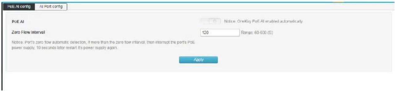
This function intelligently detects the status of the PoE port and performs related operations through software.
1) When there is no data transmission for a long time on the PoE port, the power supply of the PoE will be automatically interrupted, and the power will be automatically restored after 10 seconds.
2) The total power of the switch PoE is detected. When the total power of all the PoE ports of the switch exceeds the power set in the "maximum total power supply", the power supply of the PoE port is interrupted until the total power is reduced to the value of "maximum total power supply".
Click "PoE Management" >> "Intelligent power supply configurarion" into the intelligent power supply configuration interface:
Intelligent power supply
Turn on/off via the "AI Power" button on the front panel of the switch.
Zero flow duration
Set the time (in seconds) for no traffic on the PoE port. After the setting is successful, if the software detects that the PoE port has no data transmission within the set time, it then interrupts the PoE power supply and resumes power supply after 10 seconds.
Chapter 6: Layer 2 Management
6.1 MAC Address Table
The main function of the Ethernet switch is to forward the packet at the data link layer, that is, to output the packet to the corresponding port according to the destination MAC address of the packet. The address table contains the address information for forwarding packets between ports. It is the basis for the switch to implement fast packet forwarding. The entries in the address table can be updated and maintained through automatic learning and manual binding. Most address table entries are created and maintained through the automatic learning function. For some relatively fixed connections, manual Binding can improve the efficiency of the switch. The MAC address filtering function enables the switch to filter data frames that are not expected to be forwarded, thus improving network security.
Click "Layer 2 Management" >> "MAC Address Table" enter into the interface of MAC address table, as shown in below figure:
| Add | Del | Expired Time(s): 300 Set | |||
| Index | MAC Address | VI.AN | Port | Type | |
| 1 | 48-6a-63-81-80-97 | 1 | G6 | dynamic Bind | |
| 2 | 00-23-24-05-01-0b | 1 | G12 | dynamic Bind |
Total 2 records Total 1 pages Current 1 page First < Previous Next > Last
Add
In the dialog box that is displayed, enter "MAC Address", "VLAN", "Port", and click "Add" to complete the static binding

Delete
First select the item in the address table that you need to delete, and then click delete to complete the deletion.
Lease time remaining
Enter the aging time of the address here, click "Settings" and the aging time is set successfully. The aging time is set only for dynamic addresses. Statically added addresses are not affected by aging time.

Note:
If the port of the address is specified incorrectly, or the port (or device) is manually changed during use, the static address entry must be reset, otherwise the switch will not forward the data correctly. Once the static address is set, if the network device with this address is connected to another port of the switch, the switch will not be able to recognize it dynamically. Therefore, you must ensure that the entries in the static address table are valid and valid. Any address added to the static address table cannot be added to the filter address table at the same time, nor can it be dynamically bound by the port.

Description:
If the aging time is too long, the switch will store too many obsolete address entries in the address table of the switch, thus exhausting the resources of the address table. As a result, the switch cannot update the address table according to changes in the network. If the aging time is too short, the address table will be refreshed too fast. The destination address of a large number of received packets cannot be found in the address table, so that the switch can only broadcast these packets to all ports, which will reduce the performance of the switch. It is recommended to use the default value.
6.2 VLAN Configuration
Ethernet is a data network communication technology based on shared communication medium of CSMA/CDCSMA (Carrier Sense Multiple Access/Collision Detection). When the number of hosts is large, collisions may occur, broadcast flooding, and performance. Significant drops and even problems such as the network being unavailable. Although the LAN interconnection through the switch can solve the serious problem of collision (Collision), it still cannot isolate the broadcast message. In this case, a VLAN (Virtual Local Area Network) technology has emerged, which divides a LAN into multiple logical LANs - VLANs. Each VLAN is a broadcast domain. The communication between hosts in a VLAN is the same as that in a LAN. The VLANs cannot communicate with each other directly. In this way, broadcast packets are restricted to one VLAN. As shown below:
![graph TD A["Router"] --> B["Switch A"] A --> C["Switch B"] B --> D["VLAN2"] B --> E["VLAN3"] C --> F["VLAN10"] C --> G["VLAN10"]](/content/2026/08/1621927/images/8f5bfb8643ede8b02b35401b6e69258e449fac665479bb796f28d95082d2c8fd.jpg)
Compared with traditional Ethernet, VLAN has the following advantages:
Controlling the scope of the broadcast domain: Broadcast packets in the LAN are confined to one VLAN, saving bandwidth and improving network processing capability.
Enhanced LAN security: Since packets are isolated at the data link layer by the VLAN-divided broadcast domain, hosts in each VLAN cannot communicate directly, and packets must be sent through network layer devices such as routers or Layer 3 switches. Perform three-layer forwarding.
Simplify network management. The hosts of the same virtual workgroup are not limited to a certain physical scope, which simplifies the management of the network and facilitates the establishment of workgroups by people in different regions.
This managed switch supports 802.1Q VLANs, MAC-based VLANs, and port-based VLANs. In the default configuration, the VLAN is 802.1Q VLAN mode.
Port-based VLANs are based on the principle that VLANs are assigned based on the interface number of the switching device. The network administrator configures a different PVID for each interface of the switch, that is, the VLAN to which an interface belongs by default. When a data frame enters the switch interface, if there is no VLAN tag and the PVID is configured on the interface, the data frame will be tagged with the PVID of the interface. If the incoming frame already has a VLAN tag, the switch will not add a VLAN tag even if the interface has been configured with a PVID.
6.2.1 VLAN State
Click Layer 2 Management >> VLAN Configuration >> VLAN Status to enter the VLAN status interface, as shown below:

Port
After successfully creating the VLAN, set the port properties in the "Port" list. You can set Tagged and Untagged.
VLAN
After the VLAN is successfully created, the configured VLAN will be displayed in the "VLAN" list.
6.2.2 VLAN Configuration
This page can configure VLANs and configure VLAN mode for each port.
Click Layer 2 Management >> VLAN Configuration >> VLAN Configuration in the navigation bar to enter the VLAN configuration interface, as shown in the following
| Port | Vlan Mode | PVID | vlan untag | vlan tag |
| Select All | hybrid | |||
| G1 | access | 1 | 1 | |
| G2 | access | 1 | 1 | |
| G3 | access | 1 | 1 | |
| G4 | access | 1 | 1 | |
| G5 | access | 1 | 1 | |
| G6 | access | 1 | 1 | |
| G7 | access | 1 | 1 | |
| G8 | access | 1 | 1 | |
| G9 | access | 1 | 1 | |
| G10 | access | 1 | 1 | |
| G11 | access | 1 | 1 | |
| G12 | access | 1 | 1 | |
| G13 | access | 1 | 1 | |
| G14 | access | 1 | 1 | |
| G15 | access | 1 | 1 | |
| G16 | access | 1 | 1 | |
| G17 | access | 1 | 1 | |
| G18 | access | 1 | 1 |
VLAN modes:
ACCESS: The port can belong to only one VLAN. The egress rule is UNTAG. Access port is the port that connects to the user terminal device. When an ACCESS type port is added to another VLAN, the original VLAN is automatically removed.
TRUNK: A port can allow multiple VLANs to pass through, and can receive and send packets of multiple VLANs. In the network, the VLANs are often connected to different switches. The default egress rule of the trunk port is TAG. When the port forwards data from default VLAN, the VLAN information is removed. When the port forwards data from other VLANs, the original VLAN information is retained.
HYBRID: A port can allow multiple VLANs to pass through. It can receive and send packets of multiple VLANs. It can be used to connect between network devices and connect to user devices. The egress rule of an interface can be flexibly configured based on the actual conditions of the device connected to the port.
PVID:
PVID (Port VLAN ID) is the default VID of the port. When a packet received by a port does not contain a VLAN tag, the switch inserts a VLAN tag based on the PVID value of the receiving port and forwards the packet.
When VLANs are divided in the LAN, PVID is an important parameter of each port, indicating which VLAN the port belongs to by default. It has two uses:
When a port receives an untagged packet, it inserts a VLAN tag for the packet based on the PVID.
The PVID specifies the default broadcast domain of the port. When the port receives the UL packet or the broadcast packet, the switch broadcasts the data packet in the default VLAN of the port.
The VLAN type of a port is essentially the way how the switch processes the VLAN tag of the inbound and outbound packets. Details below:
| Port type | Receiving message processing | Processing when sending a message | |
| VLAN untag | VLAN tag | ||
| Access | Receive the packet and add the default VLAN tag to the packet, that is, the PVID of the input port. | When VID=port PVID, the message is received.When the VID ≠ port PVID, the packet is discarded. | After the tag is removed, the message is sent. |
| Trunk | Receives a packet when the VID belongs to the VLAN ID that the port is allowed to pass.Packets are discarded when the VID does not belong to the VLAN ID allowed by the port. | When the default VLAN data of the port is forwarded, the packet is sent after the tag is sent, and the rest of the original tag is sent. | |
| Hybrid | When the egress rule is configured as TAG, the original tag is sent to send the packet.When the egress rule is configured as UNTAG, the packet is sent after the tag is sent. | ||
Configuration example
Add ports G2 to VLAN 10:

Add ports G2-G6 to VLAN10, just change the PVID to 10 for the corresponding ports:
| VLAN State | VLAN Config | Voice VLAN Config | MAC VLAN Config | IP VLAN Config | Manage VLAN Config |
| Port | VLAN Mode | PVID | VLAN Untag | VLAN Tag | |
| Select All | hybrid | √ | |||
| G1 | access | √ | 1 | 1 | |
| G2 | access | √ | 10 | 10 | |
| G3 | access | √ | 10 | 10 | |
| G4 | access | √ | 10 | 10 | |
| G5 | access | √ | 10 | 10 | |
| G6 | access | √ | 10 | 10 | |
| G7 | access | √ | 1 | 1 | |
Add port G9 to multiple VLANs:
| VLAN State | VLAN Config | Voice VLAN Config | MAC VLAN Config | IP VLAN Config | Manage VLAN Config |
| Port | VLAN Mode | PVID | VLAN Untag | VLAN Tag | |
| Select All | hybrid | √ | |||
| G1 | access | √ | 1 | 1 | |
| G2 | access | √ | 10 | 10 | |
| G3 | access | √ | 10 | 10 | |
| G4 | access | √ | 10 | 10 | |
| G5 | access | √ | 10 | 10 | |
| G6 | access | √ | 10 | 10 | |
| G7 | access | √ | 1 | 1 | |
| G8 | access | √ | 1 | 1 | |
| G9 | hybrid | √ | 1 | 1-5 | 10 20 |
Description:
When configuring a port to belong to multiple VLANs, first change the mode to Trunk or Hybrid mode, and then configure VLAN tag information. You need to pay attention to the configuration of the tag information. The space indicates the discontinuous VLAN. A hyphen “-” indicates consecutive VLANs.
For example, the VLAN tag in the above figure is "10 20", which means that VLAN 10 and VLAN 20 VLAN tags are supported.
If VLAN untag is "1-5", that means that all VLANs from VLAN 1 to VLAN 5 are supported.
6.2.3 VoiceVLAN Configuration
A voice VLAN is a VLAN that is divided into voice data streams for users. By creating a voice VLAN and adding a port connected to a voice device to a voice VLAN, you can enable voice data to be transmitted in the voice VLAN. This facilitates QoS (Quality of Service) configuration and improves voice. The priority of traffic transmission ensures the quality of the call.
Click Layer 2 Management >> VLAN Configuration >> Voice VLAN Configuration to enter the voice VLAN interface, as shown in below figure:
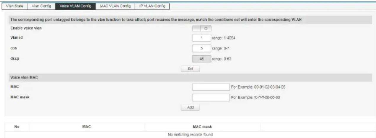
Enable Voice VLAN
Enable/disable the Voice VLAN function.
VLAN ID
The value of the VLAN ID is in the range of 1 to 4094. Such as: 1-3, 5, 7, 9. VLAN 1 is the default. Other VLANs must exist and are added to the port that needs to be linked in untag mode.
cos
Fill in the CoS value of the Voice VLAN, ranging from 0-7. After setting the COS value, you need to set the COS queue mapping in QOS. This sets voice traffic priority level.
DSCP
Fill in the DSCP queue mapping of the voice VLAN, ranging from 0 to 63. After setting the DSCP value, you need to set the DSCP queue mapping in QOS. This sets voice traffic priority level.
MAC
Enter the OUI (Unique Identifier) address of the specified IP phone or voice client. E.g: 0812-f231-05e1.
MAC Mask
Fill in the mask, e.g: ffff-ff00-0000.
Description:
VLAN 1 cannot be specified as a voice VLAN. To facilitate management, it is recommended to assign different VLANs for voice services and data services.
To ensure the normal use of various functions, assign a different VLAN ID to the default VLAN of the voice VLAN and interface.
At the same time, only one VLAN of an interface can be set as a voice VLAN.
VLAN mapping, VLAN stacking, and application traffic policies are not allowed on the interface enabled with the voice VLAN.
You cannot configure the VLAN ID to 0 on the IP phone.
6.2.4 MAC VLAN Configuration
MAC VLAN is another method of dividing a VLAN. The VLAN is divided according to the MAC address of each host. That is, the MAC address of each host is divided into VLANs. If the untagged (without VLAN tag) frame is received, the VLAN ID is added according to the table.
Advantage: When the physical location of the end user changes, there is no need to reconfigure the VLAN. After binding, the device corresponding to the MAC address can switch ports as long as it is connected to the member port of the corresponding VLAN without changing the configuration of the VLAN member. Improve end-user security and access flexibility.
Disadvantages: Only applicable to scenarios where the network card is not frequently replaced and the network environment is relatively simple. All members in the network need to be defined in advance.
Click Layer 2 Management >> VLAN Configuration >> MAC VLAN Configuration in the navigation bar to enter the MAC VLAN interface, as shown in below figure:

VLAN ID
Enter the ID of the VLAN to be added, in the range of 1 to 4094. Such as: 5,7,9. VLAN 1 is the default and cannot be set. Other VLANs must exist and are added to the port that needs to be linked in untag mode.
MAC
Fill in the client's MAC address. Enter the completion and click the "Add" button.
6.2.5 IP VLAN Configuration
A VLAN based on the IP protocol assigns different VLAN IDs to packets based on the IP address to which the packets are received. The advantage is that the VLAN is divided based on IP, and the service type provided in the network is bound to the VLAN, which is convenient for management and maintenance.
The disadvantage is that you need to initially configure the mapping table of all IP protocols and VLAN IDs in the network. It is necessary to analyze the address format of various IP protocols and perform corresponding conversions, which consumes more resources of the switch, and has a slight disadvantage in speed.
Click Layer 2 Management >> VLAN Configuration >> IP VLAN Configuration to enter the IP VLAN interface, as shown in below figure:

VLAN ID
Enter the ID of the VLAN to be added, in the range of 1 to 4094. Such as: 5,7,9. VLAN 1 is the default and cannot be set. Other VLANs must exist and are added to the port that needs to be linked in untag mode.
IP
Fill in the client's IP address. Click "Add" to set it.
6.3 GVRP
GVRP (GARP VLAN Registration Protocol, GARP VLAN registration agreement) is GARP (Generic Attribute Registration Protocol) application. It achieves the purpose of creating or deleting VLAN by dynamically registering and replacing VLAN information on the port, and spreading VLAN information to other switches, reducing the tedious manual operation when configuring VLAN.
GARP Introduction
GARP provides a mechanism to assist exchange members in the same local area network to distribute, disseminate, and register certain information. GARP itself does not exist in the device as an entity. The application entity that follows the GARP protocol is called the GARP application and GVRP is an application of GARP. When the GARP application entity exists on a certain port of the device, the port is called the GARP application entity.
GARP application entities in the network complete the relevant information exchange by passing GARP messages. The GARP protocol defines three types of messages, namely Join, Leave and Leave All messages. The three types of messages complete the registration or cancellation of related attribute information.
Join message: When a GARP application entity wants other devices to register its own attribute information, it will send a Join message to the outside; when it receives a Join message from another entity or the device has statically configured some attributes needs other GARP application entities to register, it will also send out Join messages.
Leave message: When a GARP application entity wants other devices to cancel its own attribute information, it will send a Leave message; when it receives a Leave message from other entities to cancel some attributes or statically cancel some attributes, it will also Send a Leave message outside.
Leave All message: After each GARP application entity is started, the Leave All timer will be started at the same time. When the timer expires, the GARP application entity will send a LeaveAll message to the outside, and the LeaveAll message is used to cancel all attributes, so that other GARP application entities can re-register all attribute information on the entity.
Through message exchange, all attribute information to be registered can be propagated to all GARP application entities in the same local area network.
The time interval for sending GARP messages is controlled by a timer. The GARP protocol defines four timers to control the sending cycle of GARP messages:
Hold timer: When the GARP application entity receives registration information sent by other devices, it will not immediately send the registration information as a Join message, but start the Hold timer. When the timer expires, the GARP application entity will All registration information received during this period is sent out in the same Join message, thereby saving bandwidth resources.
Join timer: The GARP application entity can ensure the reliable transmission of the message by sending each Join message twice. When the Join message sent for the first time is not answered, the GARP application entity will send the Join message for the second time. The time interval between two Join message sending is controlled by the Join timer.
Leave timer: When a GARP application entity wants to cancel certain attribute information, it will send a Leave message, and the GARP application entity that receives the message starts the Leave timer. If it does not receive the Join message before the timer expires, it will log out the attribute information.
Leave All timer: After each GARP application entity is started, it will start the LeaveAll timer at the same time. When the timer expires, the GARP application entity will send a LeaveAll message to make other GARP application entities re-register all attribute information on the entity. Then start the LeaveAll timer to start a new cycle.
GVRP Introduction
GVRP is an application of GARP. Based on the working mechanism of GARP, it maintains the VLAN dynamic registration information in the device and spreads the VLAN information to other devices.
After the device starts the GVRP feature, it can receive VLAN registration information from other devices and dynamically update the local VLAN registration information, including the current VLAN members, which port these VLAN members can reach, etc.; at the same time, the device can register the local VLAN information propagate to other devices to make the VLAN information of all devices in the same LAN consistent. The VLAN registration information propagated by GVRP includes not only the static registration information manually configured locally, but also the dynamic registration information from other devices.
In this switch, only TRUNK type ports can be used as GVRP application entities to maintain the VLAN registration information of the switch. There are three port registration modes for GVRP: Normal, Fixed and Forbidden. Each mode is described as follows,
Normal mode: Allow the port to dynamically register and deregister VLAN, and propagate dynamic VLAN and static VLAN information.
Fixed mode: Forbid the port to dynamically register and deregister VLAN, and only propagate static VLAN information, not dynamic VLAN information. The port in fixed mode only allows the static VLAN information to which the port belongs to pass.
Forbidden mode: Forbid the port to dynamically register and deregister VLAN, and do not transmit any VLAN information except VLAN1. Forbidden mode ports, only allow the system default VLAN VLAN1 to pass.
6.3.1 Global configuration
GVRP global configuration information can be set on this page
Click Layer 2 Management >>Loop protech >>Global configuration

Global configuration
GVRP function: Select whether to enable the GVRP function of the switch.
Create Dynamic VLAN: Choose whether to enable the dynamic VLAN creation function of the switch.
6.3.2 Port configuration
This page can configure the GVRP port parameters.
Click "Layer 2 Management" >> "GVRP Configuration" >> "Port Configuration" in the navigation bar to enter the port configuration interface, as shown below:
| Port | Enable GVRP | Registration Mode | Applicant State | Join Timer(cs) | Leave Timer(cs) | LeaveAll Timer(cs) |
| Select All | normal | normal | ||||
| Q1 | normal | normal | 20 | 60 | 1000 | |
| G2 | normal | normal | 20 | 60 | 1000 | |
| G3 | normal | normal | 20 | 60 | 1000 | |
| G4 | normal | normal | 20 | 60 | 1000 | |
| G5 | normal | normal | 20 | 60 | 1000 | |
| G6 | normal | normal | 20 | 60 | 1000 | |
| G7 | normal | normal | 20 | 60 | 1000 | |
| G8 | normal | normal | 20 | 60 | 1000 | |
| G9 | normal | normal | 20 | 60 | 1000 | |
| G10 | normal | normal | 20 | 60 | 1000 | |
| G11 | normal | normal | 20 | 60 | 1000 | |
| G12 | normal | normal | 20 | 60 | 1000 | |
| G13 | normal | normal | 20 | 60 | 1000 | |
| G14 | normal | normal | 20 | 60 | 1000 | |
| G15 | normal | normal | 20 | 60 | 1000 | |
| G16 | normal | normal | 20 | 60 | 1000 | |
| G17 | normal | normal | 20 | 60 | 1000 | |
| G18 | normal | normal | 20 | 60 | 1000 |
Port Display the port number of the switch.
Enable GVRP Configuration port to enable or disable GVRP function.
Registration Mode Select the registration mode of the port.
Normal mode: Allow the port to dynamically register and deregister VLAN, and propagate dynamic VLAN and static VLAN information.
Fixed mode: Forbid the port to dynamically register and deregister VLAN, and only propagate static VLAN information, not dynamic VLAN information. The port in fixed mode only allows the static VLAN information to which the port belongs to pass.
Forbidden mode: Forbid the port to dynamically register and deregister VLAN, and do not transmit any VLAN information except VLAN1. Forbidden mode ports, only allow the system default VLAN VLAN1 to pass.
Join timer GARP port can send each Join data packet twice to ensure reliable transmission of messages, twice the time interval between sending is controlled by the Join timer. The value range of the Join timer is 20-1000 Centiseconds.
Leave timer The GARP port that receives the Leave packet starts the Leave timer. If the timer expires when the Join packet is not received before the time, the corresponding attribute information will be cancelled. Leave timer value the range is 60-3000 centiseconds.
LeaveAll timer After each port starts GARP, it also starts the LeaveAll timer, the port will send cyclically to the outside LeaveAll message to make other ports re-register all their attribute information. LeaveAll timer the value range of is 1000-30000 centiseconds.

Note: The LeaveAll timer must be greater than or equal to 10 times the Leave timer, and the Leave
timer must be greater than or equal to 2 times the Join timer.
GVRP Configuration steps
| Steps | Operation | Description |
| 1 | Set port type | Required operation. Set the port type to TRUNK on the Layer 2 Management >> VLAN Configuration >> VLAN Configuration page |
| 2 | Enable GVRP function | Required operation. Enable the GVRP function on the Layer 2 Management>>GVRP Configuration>>Global Configuration page. |
| 3 | Configure the port registration mode and the duration of each timer | Required operation. According to the actual application in the Layer 2 Management>>GVRP Configuration>>Port Configuration page |
6.4 Link Aggregation
The physical port is bundled into a logical port to implement the load balancing of the inbound/outbound traffic on each member port. The switch determines the port from which the packet is sent based on the port load balancing policy configured by the user. Switch to the peer. You can share traffic between member ports in an aggregation group to increase bandwidth. At the same time, each member port of the same aggregation group dynamically backs up each other, which improves connection reliability.
The member ports in the same aggregation group must have the same configuration. These configurations include STP, QoS, VLAN, port attributes and MAC address learning.
As shown in the following figure, SwitchA and SwitchB are connected through three physical Ethernet links. The three links are bundled together to form an Eth-Trunk logical link. The bandwidth of this logical link is equal to the original three Ethernet ports. The sum of the bandwidth of the physical link of the network, thereby achieving the purpose of increasing the link bandwidth.

6.4.1 Static Link Configuration
On the page, you can manually configure the aggregation group. The LACP status of the manually configured aggregation port is disabled.
Click Layer 2 Management >> Link Aggregation >> Static Aggregation Configuration enter into the static aggregation configuration interface, as shown in below figure:

Create Click the "Create" and pop-up dialog box to enter the ID of the aggregation group and click "Create". As shown below:

Delete Select the aggregation group you want to delete in the aggregation list and click "Delete" to delete.
Load Balancing Mode
Src MAC: performs load sharing based on source MAC address.
Dst MAC: performs load sharing based on the destination MAC address.
Src& Dst MAC: performs load sharing based on the exclusive OR of the source MAC address and the destination MAC address.
Src IP: load balancing based on source IP address
Dst IP: performs load sharing based on the destination IP address.
Src& Dst MAC: performs load sharing based on the exclusive OR of the source IP address and the destination IP address.
The default is load sharing based on the XOR of the source MAC address and the destination MAC address.
6.4.2 Dynamic Aggregation Configuration
The Link Aggregation Control Protocol (LACP) based on the IEEE 802.3ad standard is a protocol for implementing dynamic aggregation and de-aggregation of links. The LACP protocol exchanges information with the peer through an LACPDU (Link Aggregation Control Protocol Data Unit).
After the LACP protocol is enabled on a port, the port advertises its system priority, system MAC address, port priority, port number, and operation key to the peer through sending LACPDUs. After receiving the information, the peer compares the information with the information saved by other ports to select the port that can be aggregated. Therefore, the two parties can agree to join or exit the port.
Dynamic LACP aggregation is an aggregation that is automatically created or deleted by the system. The addition and deletion of ports in a dynamic aggregation group is automatically done by the protocol. Only ports with the same rate and duplex attributes, connected to the same device, and the same basic configuration can be dynamically aggregated.
Click Layer 2 Management >> Link Aggregation >> Dynamic Aggregation Configuration enter into the dynamic aggregation configuration interface, as shown in below figure:

System priority
The device priority is determined along with the MAC address of the system. The device with the highest priority will dominate aggregation and de-aggregation. The default is 32768.
Activity mode
Active mode: The port automatically sends LACP protocol packets periodically.
Passive mode: The port does not automatically send LACP protocol packets; it only responds to LACP protocol packets sent from the peer device.
Send mode You can select slow, fast, and no send mode.
Port priority
The port priority that becomes the aggregation member is determined. Determines the priority of the port that is a member of the aggregation group. Ports with small port priority values are preferred. If the port priority is the same, the port number will be preferred. The default is 32768.
Key value
Set the key value of the port. In the same aggregation group, you need to set the same key value.
Switch
Enable/disable LACP (Dynamic Aggregation). The default is off.
Description:
Before changing the dynamic aggregation mode, ensure that no member interfaces are added to the Eth-Trunk. Otherwise, the dynamic aggregation mode cannot be modified.
6.4.3 Link Aggregation Information
This page displays detailed information about link aggregation, including the number of ports, priority, load balancing mode, and key values in static and dynamic aggregation.
Click Layer 2 Management >> Link Aggregation >> Link Aggregation Information to enter the interface of the link aggregation information, as shown in the following figure:
| Static aggregation config | Dynamic aggregation config | Link Aggregation Information | |||||||||||
| Trunk | Mode Number Ports Port List Load Balancing | ||||||||||||
| trunk6 | Dynamic 2 G1 G2 srcdat-mac | ||||||||||||
| Trunk | Local Peer | ||||||||||||
| Name | State | The Port Number | Priority | Key Value | Sign | Connection | The Port Number | Priority | Key Value | Sign | System ID | System Priority | |
| trunk6 | G1 | Selected | 1 | 32768 | 3 | ABCDEF | UP | 4 | 32768 | 3 | ABCDEF | 60-36-CA-15-27-78 | 32768 |
| G2 | Selected | 2 | 32768 | 3 | ABCDEF | UP | 3 | 32768 | 3 | ABCDEF | 60-36-CA-15-27-78 | 32768 | |
Flags A -- LACP_Activity, B -- LACP_timeout, C -- Aggregation, D -- Synchronization, E -- Collecting, F -- Distributing, G -- Defaulted, H -- Expired
Aggregation Group: Displays the name of the aggregation group.
Mode: Displays the aggregation mode (dynamic or static) of the current aggregation group.
Number of Ports: Displays the number of currently aggregated ports.
Port List: Displays the port number that has been aggregated.
Load Balancing: Displays the load balancing mode currently in use.
6.5 MSTP Configuration
The Spanning Tree Protocol is a protocol established in accordance with the IEEE 802.1D standard to eliminate physical loops at the data link layer in a local area network. The device running the protocol discovers the loops in the network by interacting with each other and selectively blocks certain ports. Finally, the loop network structure is trimmed into a loop-free tree network structure to prevent packets from being ringed. The network network continues to proliferate and infinitely loops, avoiding the problem that the device's processing capability is reduced due to repeated reception of the same packet.
Like many protocol development processes, the spanning tree protocol is constantly updated as the network evolves, from the initial STP defined in IEEE 802.1D to the Rapid Spanning Tree Protocol (RSTP) defined in IEEE 802.1W. Then, to the latest multiple spanning tree protocol MSTP (Multiple Spanning Tree Protocol) defined in IEEE 802.1S. MSTP is compatible with RSTP and STP, and RSTP is compatible with STP. A comparison of the three spanning tree protocols is shown in the table.
| Protocol | Feature | Application |
| STP | Form a loop-free tree that resolves broadcast storms and enables redundant backups.The convergence speed is slower. | There is no need to distinguish between user or service traffic, and all VLANs share a spanning tree. |
| RSTP | Form a loop-free tree that resolves broadcast storms and enables redundant backups.Fast convergence | |
| MSTP | Form a loop-free tree that resolves broadcast storms and enables redundant backups.The convergence speed is fast. Multiple spanning trees implement load balancing between VLANs. Traffic of different VLANs is forwarded according to different paths. | It is necessary to distinguish user or service traffic and implement load sharing. Different VLANs forward traffic through different spanning trees, and each spanning tree is independent of each other. |
6.5.1 Global Configuration
Configure the global parameter configuration of the spanning tree. In some specific network environments, you need to adjust the STP parameters of some devices to achieve the best results.
Click Layer 2 Management >> MSTP Configuration >> Global Configuration in the navigation bar to enter the global configuration interface, as shown below.
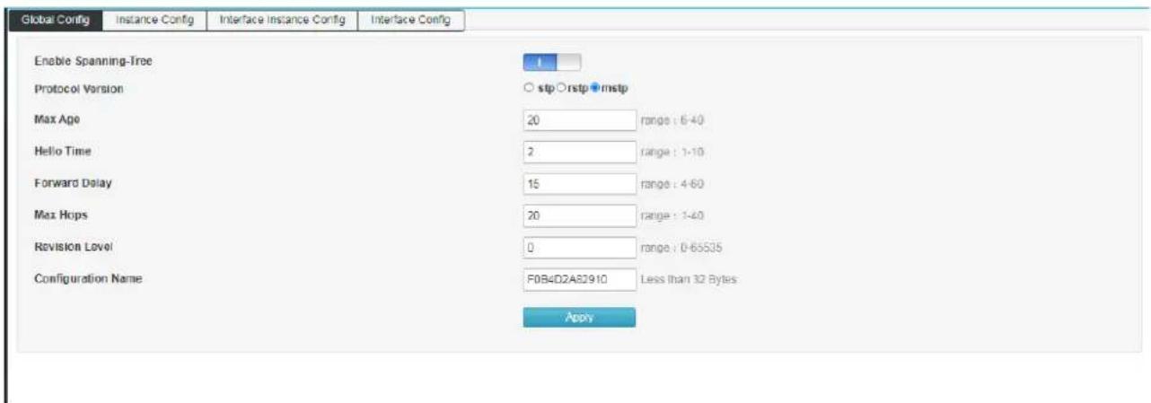
Use Enable Spanning-tree to turn spanning tree on/off
Mode :Select STP, RSTP, MSTP
Max age: indicates the maximum lifetime of the message. This value ranges from 6 to 40 seconds. The default is 20 seconds.
Hello time: indicates the period during which the message was sent. The bridge sends hello to the surrounding bridges at regular intervals.
Message. To confirm whether the link is faulty, this interval is hello time.
Forward Delay: indicates the delay of port state transition. This value ranges from 4 to 30 seconds. The default value is 15 seconds.
Max Hops: selects the maximum number of hops. This value ranges from 1 to 20 and defaults to 20. The most spanning tree in the MST domain
Large hop count is used to limit the network size of the spanning tree in the MST region. Starting from the root bridge of the spanning tree in the MST region, the number of hops is decremented by one when configuration information in domain is forwarded in each switch. The switch will discard the configuration hops with the hop count of 0. Participate in the calculation of spanning tree, which limits the size of the MST domain.
Revision: MSTP revision level. The revision level of MSTP is used to determine the assignment with the domain name and VLAN mapping table. The MST region to which the switch device belongs.
Name:MST domain name. The default value is the MAC address of the main control board of the switch.
After the setting is completed, click "Apply".

Note
The length of the transmission delay parameter of the device is related to the size of the STP. If the transmission delay is too small, a temporary loop may be introduced. If the transmission delay is too large, the network may not be able to resume connectivity for a long time. The default value is recommended.
If the aging time is too small, the switch will calculate the spanning tree frequently, and the network congestion may be misidentified as a link fault. If the aging time is too large, the switch cannot find the link fault in time and cannot recalculate the spanning tree in time. Reduce the adaptive ability of the network. The default value is recommended.
If the traffic limit is too large, the number of MSTP packets sent during each contact time will be too large, thus consuming too much network resources. The default value is recommended.
6.5.2 Instance Configuration
A switching network is divided into multiple domains by MSTP, and multiple spanning trees are formed in each domain, and the spanning trees are independent of each other. Each spanning tree is called a multiple spanning tree instance MSTI (Multiple Spanning Tree Instance), and each domain is called an MST region (MST Region: Multiple Spanning Tree Region).

Description:
An instance is a collection of multiple VLANs. By bundling multiple VLANs into one instance, you can save on communication overhead and resource utilization. The calculation of each instance topology of MSTP is independent of each other, and load balancing can be implemented on these instances. Multiple VLANs of the
same topology can be mapped to an instance. The forwarding state of these VLANs on the port depends on the state of the port in the corresponding MSTP instance.
Simply, it is the mapping of one or more VLANs to a specified MST instance. One or more VLANs can be assigned to one spanning tree instance at a time.
Click Layer 2 Management >> MSTP Configuration >> Instance Configuration in the navigation bar to enter the instance configuration interface, as shown in the following figure:

MSTI ID: Select any instance number within 1–63.
Priority: Set the priority of the specified instance, which must be a multiple of 4096. Its range is 0 to 65535, the default value is 32768.
VLAN Mapped: Enter the VLAN to be mapped. VLAN mapping can modify the packets carried VLAN tag.
Provide the following four mapping relationships:
1:1 VLAN mapping: Replace the VLAN tag carried in a packet from a specific VLAN with a new VLAN tag.
N:1 VLAN mapping: Replace different VLAN tags carried in packets from two or more VLANs with the same VLAN tag.
1:2 VLAN mapping: Apply the outer VLAN tag to the packet carrying a VLAN tag, so that the packet carries two VLAN tags.
2:2 VLAN mapping: Replace the inner and outer VLAN tags of the packets carrying the two VLAN tags with the new VLAN tags.
6.5.3 Port Instance Configuration
Here is the instance to show how to configure the switch port:
Click Layer 2 Management >> MSTP Configuration >> Port Instance Configuration in the navigation tree to enter the port instance configuration interface, as shown here.
| Global Config | Instance Config | Interface Instance Config | Interface Config | |||||
| MSTI ID: 0✓ | ||||||||
| Interface | Ports List | Enable Status | MSTI ID | Priority | Admin Cost | Oper Cost | Role | State |
| Select All | ||||||||
| G1 | G1 | ● | 0 | 128 | 0 | 20000 | Disabled | discarding |
| G2 | G2 | ● | 0 | 128 | 0 | 20000 | Designated | forwarding |
| G3 | G3 | ● | 0 | 128 | 0 | 20000 | Disabled | discarding |
| G4 | G4 | ● | 0 | 128 | 0 | 20000 | Designated | forwarding |
| G5 | G5 | ● | 0 | 128 | 0 | 20000 | Disabled | discarding |
| G6 | G6 | ● | 0 | 128 | 0 | 200000 | Designated | forwarding |
| G7 | G7 | ● | 0 | 128 | 0 | 20000 | Disabled | discarding |
| G8 | G8 | ● | 0 | 128 | 0 | 20000 | Disabled | discarding |
| G9 | G9 | ● | 0 | 128 | 0 | 20000 | Disabled | discarding |
| G10 | G10 | ● | 0 | 128 | 0 | 20000 | Disabled | discarding |
| G11 | G11 | ● | 0 | 128 | 0 | 20000 | Disabled | discarding |
| G12 | G12 | ● | 0 | 128 | 0 | 20000 | Designated | forwarding |
| G13 | G13 | ● | 0 | 128 | D | 20000 | Disabled | discarding |
| G14 | G14 | ● | 0 | 128 | D | 20000 | Disabled | discarding |
| G15 | G15 | ● | 0 | 128 | D. D. D. D. D. D. D. D. D. D. D. D. D. D. D. D. D. D. D. D. D. D. D. D. D. D. D. D. D. D. D. D. D. D. D. D. D. D. D. D. D. D. D. D. D. D. D. D. D. D. D. | |||
MSTID: Select the configured instance in the Instance Configuration from the drop-down menu.
Priority: Select the priority of the port. A smaller value indicates a higher priority.
The interface priority can affect the role of the interface on the specified MSTI. You can configure different priorities on the same interface on different MSTIs to enable traffic of different VLANs to be forwarded along different physical links. When the interface priority changes, MSTP recalculates the role of the interface and performs state transition.
Path cost: The reference value used to select the path and calculate the path cost. Also determine if the port will be selected as the root port. A smaller value indicates a higher priority (0 means no setting).
Role: Displays the role that the port plays in the spanning tree.
Disable: The port whose physical connection is broken.
Designated: The port responsible for forwarding data to downstream network segments or devices.
Root: The port with the lowest path cost to the root bridge, responsible for forwarding data to the root bridge.
Alternate: The backup port of the root port and the master port.
Master port: Connect multiple spanning tree domains to the total root, located on the shortest path from the entire domain to the total root.
Backup (backup port): Specifies the backup port of the port.
Status: Displays the current working status of the port.
Discarding: A port with a physical connection disconnected.
Forwarding: accepts and forwards data, receives and sends protocol packets, and performs address learning.
Blocking: Does not receive or forward data, but does not send protocol packets. No address learning is done.
Learning: Do not receive or forward data, receive and send protocol messages, and learn addresses.
Description: The IEEE 802.1D standard updated cost definition is used to reflect the STP overhead of a broadband link with a rate lower than 1 Gbit/s (see the table below):
| Bandwidth | STP cost |
| 4 Mbit/s | 250 |
| 10 Mbit/s | 100 |
| 16 Mbit/s | 62 |
| 45 Mbit/s | 39 |
| 100 Mbit/s | 19 |
| 155 Mbit/s | 14 |
| 622 Mbit/s | 6 |
| 1 Gbit/s | 4 |
| 10 Gbit/s | 2 |

Note:
For a port directly connected to the terminal, set the port as an edge port and enable BPDU protection. In this way, the port can be quickly migrated to the forwarding state, and the network can be secured.
6.5.4 Port Configuration
In some specific network environments, it is necessary to adjust the STP parameters of some switch device interfaces in order to achieve the best results.
Click Layer 2 Management >> MSTP Configuration >> Instance configuration in the navigation bar to enter the port management interface, as shown below.
| Global Config | Instance Config | Interface Instance Config | Interface Config | |||||||
| Interface | Ports List | Enable Spanning-Tree | Root Guard | BPDU Guard | Admin Edge | Oper Edge | Admin Point-to-Point | Oper Point-to-Point | ||
| Select All | Og | Og | Og | Auto✓ | Auto✓ | |||||
| Q1 | Q1 | I | Og | Og | Auto✓ | NO | Auto✓ | Yes | ||
| Q2 | Q2 | I | Og | Og | Auto✓ | NO | Auto✓ | Yes | ||
| Q3 | Q3 | I | Og | Og | Auto✓ | NO | Auto✓ | NO | ||
| Q4 | Q4 | I | Og | Og | Auto✓ | NO | Auto✓ | Yes | ||
| Q5 | Q5 | I | Og | Og | Auto✓ | NO | Auto✓ | NO | ||
| Q6 | Q6 | I | Og | Og | Auto✓ | Yes | Auto✓ | Yes | ||
| Q7 | Q7 | I | Og | Og | Auto✓ | NO | Auto✓ | NO | ||
| Q8 | Q8 | I | Og | Og | Auto✓ | NO | Auto✓ | NO | ||
| G9 | G9 | I | Og | Og | Auto✓ | NO | Auto✓ | NO | ||
| G10 | G10 | I | Og | Og | Auto✓ | NO | Auto✓ | Yes | ||
| G11 | G11 | I. I. I. I. I. I. I. I. I. I. I. I. I. I. I. I. I. I. I. I. I. I. I. I. I. I. I. I. I. I. I. I. I. I. I. I. I. I. I. I. I. I. I. I. I. I. I. I. I. I. I. 11111111111111111111111111111111111111111111111111111111111111111111111111111111111111111 | ||||||||
BPDU Guard radio. Select whether to enable BPDU protection. There are two cases of opening and not opening. The default is not to open.
When the BPDU protection function is enabled on the device, if the interface receives BPDUs, the device shuts down these interfaces and notifies the NMS. The closed interface can only be manually restored by the network administrator.
The Edge edge port should be connected directly to the user terminal instead of another switch or network segment. Edge port can be fast Transition to the forwarding state quickly, because on the edge port, changes in the network topology do not create loops. When you set a port to an edge port, the Spanning Tree Protocol allows it to quickly transition to the forwarding state. It is recommended to manage the Ethernet ports directly connected to the user terminal as edge ports so that they can quickly transition to the forwarding state.
Point-to-Point selects Force_True, Force_False, and Auto.
6.5.5 Spanning Tree Networking Example
Topology overview:
Switch A, Switch B, Switch C, and Switch D all run MSTP. To achieve load sharing between VLAN10 and VLAN20, MSTP introduces multiple instances. MSTP can set up a VLAN mapping table to associate VLANs with spanning tree instances. Example 1 maps to VLAN 10, and Example 2 maps to VLAN 20.

Operation Steps
1) Configure the Layer 2 forwarding function of the equipment in the ring network, create VLAN10 vlan20 on switch A, switch B, switch C and switch D. Click the "Layer 2 Management >> VLAN Configuration >> VLAN Configuration" menu in the navigation tree to enter the "VLAN Configuration" interface, select the mode as tagged and click "Add" to complete the configuration, as shown in the figure below.
| Vlan State | Vlan Config | Voice VLAN Config | MAC VLAN Config | IP VLAN Config | ||||||||||||||
| Vlan | Port | |||||||||||||||||
| G1 | G2 | G3 | G4 | G5 | G6 | G7 | G8 | G9 | G10 | G11 | G12 | G13 | G14 | G15 | G16 | G17 | G18 | |
| 1 | ∅ | ∅ | ∅ | ∅ | ∅ | ∅ | ∅ | ∅ | ∅ | ∅ | ∅ | ∅ | ∅ | ∅ | ∅ | ∅ | ∅ | ∅ |
| 2 | ∅ | ∅ | ∅ | ∅ | ∅ | ∅ | ∅ | ∅ | ∅ | ∅ | ∅ | ∅ | ∅ | ∅ | ∅ | ∅ | ∅ | ∅ |
| 10 | ∅ | ∅ | ∅ | ∅ | ∅ | ∅ | ∅ | ∅ | ∅ | ∅ | ∅ | ∅ | ∅ | ∅ | ∅ | ∅ | ∅ | ∅ |
| 20 | ∅ | ∅ | ∅ | ∅ | ∅ | ∅ | ∅ | ∅ | ∅ | ∅ | ∅ | ∅ | ∅ | ∅ | ∅ | ∅ | ∅ | ∅ |
2) Configure switch A/B/C/D to the domain with the domain name 12345678. Click the "Layer 2
Management> MSTP Configuration> Global Configuration" menu in the navigation tree, enter the "Global Configuration", fill in the corresponding configuration, and the interface is shown in the figure below.


3) Create instance MSTI1 and instance MSTI2. Click the "Layer 2 Management> MSTP Configuration> Instance Configuration" menu in the navigation tree, enter the "Instance Configuration", fill in the corresponding parameters, and click "Add". The interface is as shown in the figure below.


| No | MSTI ID | Priority | Vlan Mapped | Bridge ID | Regional Root | Internal Path Cost | Time Since Topo- change | Topo-change Count | |
| 1 | 0 | 4098 | 1-9 11-19 21-4094 | 1.000 F0:B4:D2:A6:28:10 | 1.000 F0:B4:D2:A6:28:10 | 0 | 331 | 4 | Set |
| 2 | 1 | 4098 | 10 | 1.001 F0:B4:D2:A8:29:10 | 1.001 F0:B4:D2:A8:29:10 | 0 | 30 | 0 | Set Del |
| 3 | 2 | 4095 | 20 | 1.002 F0:B4:D2:A8:29:10 | 1.002 F0:B4:D2:A8:29:10 | 0 | 18 | 0 | Set Del |
4) In the domain name 12345678, configure the root bridge and backup root bridge of MSTI1 and MSTI2, configure switch A as the root bridge of MSTI1, and configure switch A as the backup root bridge of MSTI2. Click the "Layer 2 Management> MSTP Configuration> Instance Configuration" menu in the navigation tree, enter the "Instance Configuration", fill in the corresponding parameters, and click "Add". The interface is as shown in the figure below.

5) In the domain 12345678, configure the root bridge and backup root bridge of MSTI1 and MSTI2, configure switch A as the root bridge of MSTI2, and configure switch B as the backup root bridge of MSTI1. The operation steps are the same as 5, so I won't repeat them. After the above configuration, the network is pruned into a tree shape to achieve the purpose of eliminating loops.

Note:
When configuring switch A, change the priority of MSTI1 to 0 and the priority of MSTI2 to 4096.
When configuring switch B, change the priority of MSTI1 to 4096 and the priority of MSTI2 to 0. The configuration method is the same as Switch A.
6.6 ERPS configuration
ERPS (Ethernet Ring Protection Switching) is an Ethernet ring network link layer technology with high reliability and stability. When the Ethernet ring is complete, it can prevent broadcast storms caused by the data loop, and when the Ethernet ring has a link failure, it can quickly restore the communication path between each node on the ring network, and has a high convergence speed.
A ring-connected Ethernet network topology is called an ERPS ring. The ERPS ring is divided into a main ring and a sub-ring. By default, the ERPS ring is the main ring. You can configure the ERPS ring as a sub-ring. An ERPS ring can consist of a single main ring or multiple ring networks. There can be multiple main rings and multiple sub-rings in multiple ring networks.
![graph TD A["Device A\nOwner node\nPort A2"] -->|Port A1| B["Device B\nNeighbor node\nPort B2"] B -->|RPL| A C["Device C\nInterconnection node\nPort C3"] -->|Port C1| D["Device D\nInterconnection node\nPort D2"] D -->|Port D1| C E["Device E\nOwner node"] -->|Port E1| F["Device F\nNeighbor node\nPort…](/content/2026/08/1621927/images/fd8621bc6b477bc4452e1c9a1928b359f9843ae6a56ad07ef147da3437b84e6d.jpg)
Figure 1 ERPS network diagram
ERPS ring and ring type
The ring is divided into major ring and sub ring
Major Ring: It is a ring-connected Ethernet network topology, as shown in Major ring in Figure 1
Sub-ring: The sub-ring is a non-closed-loop topology. It is connected to other rings or networks through intersecting nodes and it returns to the intersecting nodes.
The channels belonging to other rings or networks together form a closed-loop topology, as shown in Sub ring in Figure 1.
RPL (Ring Protection Link), each ERPS ring (whether it is a major ring or a sub-ring) has only one RPL. When the ERPS ring is in the Idle state, the RPL link is in a blocked state and data packets are not forwarded to avoid loops.
Node role and port role
Each device on the ERPS ring is called a node. The role of the node is determined by the user's configuration and is divided into:
Owner Node: Responsible for blocking and releasing the port on the RPL on this node to prevent the formation of loops, thereby performing link switching.
Neighbor Node: A node connected to the Owner node on the RPL, which cooperates with the Owner node to block and release the port on the RPL on the node to perform link switching.
Normal Node: Responsible for receiving and forwarding protocol messages and data messages in the link.
Interconnection Node: A node that connects multiple rings in the multi-ring model. The interconnection node belongs to the sub-ring, the major ring has no interconnection node. In the protocol message upload mode of the link between the sub-ring interconnection nodes, the protocol message of the sub-ring is terminated at the interconnection node and the data message is not terminated.
The types of ERPS ring member ports are determined by the user's configuration and are divided into the following three types:
RPL port: the ports at both ends of RPL (Ring Protection Link).
Common port: Common port can receive and forward protocol messages and data messages in the link.
Interconnection port: Interconnection node port is the port connecting the sub-ring to the main ring.
ERPS Instance and load balancing
A ring in the ERPS network can support multiple instances, and each instance is a logical ring. Each instance has its own protocol channel and data channel, as well as the master node and neighbor nodes; each instance acts as an independent protocol entity, maintaining its own state and data.
Packets with different ring IDs are distinguished by the destination MAC address (the last byte of the destination MAC address represents the ring ID); packets with the same ring ID are distinguished by the VLAN ID it carries to distinguish the ERPS instance to which they belong, that is, the packet The ring ID and VLAN ID uniquely identify an instance.
In the same ring network, there may be data traffic of multiple VLANs at the same time. ERPS multi-instance can realize the load sharing of traffic, that is, the traffic of different VLANs are forwarded along different paths.
The ERPS ring network can be divided into control VLAN and protection VLAN:
Control VLAN: used to transmit ERPS protocol messages. The control VLAN is not visible to users and the system can only automatically determine which control VLANs the ERPS ring member ports add. Each ERPS instance has its own control VLAN.
Protected VLAN: In contrast to the control VLAN, the protected VLAN is used to transmit data packets. Each ERPS instance has its own protection VLAN. The protection VLAN is implemented by configuring a spanning tree instance.
By configuring multiple ERPS instances on the same ring network, different ERPS instances send traffic of different VLANs to achieve different topologies of data traffic of different VLANs in the ring network, thereby achieving the purpose of load sharing.
ERPS Protocol message
R-APS (Ring Automatic Protection Switching) The message is an ERPS protocol message. The protocol provides the function of setting R-APS message level. The node does not process packets with a higher R-APS packet level than itself. The R-APS packet levels of nodes in the same instance on the same ring must be the same.
Message types include:
(NR, RB) (No Request, RPL Block) The message is sent by the Owner node in the Idle state to notify other nodes that the RPL port is blocked. After receiving the (NR, RB) message, other nodes release their trouble-free ports and update their MAC address table entries.
When the link is stable in the Idle state, the Owner node periodically sends (NR, RB) messages.
NR (No Request) After the link failure recovers, the message is sent by the node where the recovery port is located. The Owner node starts the WTR timer after receiving the NR message, and stops sending the NR message after the node where the recovery port receives the (NR, RB) message.
SF (Signal Fail) Message
When the link fails to send and receive signals, it is sent by the node where the failed port is located. After receiving the SF message, the Owner and Neighbor nodes release their RPL ports. Before the fault is eliminated, the node where the faulty port is located periodically sends SF packets.
MS (Manual Switch) Message
It is sent by the node configured with MS mode, and the port configured with MS mode is blocked. After receiving the MS message, other nodes release their own trouble-free ports and update their MAC address table entries. When the link is in the MS state, MS messages are sent periodically.
FS (Forced Switch) Message
Sent by the node configured with FS mode, the port configured with FS mode is blocked, and other nodes release all their ports after receiving the FS message and update their MAC address table entries. When the link is in the FS state, FS packets are sent periodically.
Flush Message
If the topology of the sub-ring changes, the interconnected node sends a Flush message in the form of broadcast to notify the main ring to refresh the MAC address table entries
Virtual channel and non-virtual channel
Protocol packets of the major ring are only transmitted within the major ring. Data packets of the sub-ring can be transparently transmitted to the main ring. There are two modes for the transmission of sub-ring protocol messages, virtual channel mode and non-virtual channel mode.
When the sub-ring is in the non-virtual channel mode, the protocol packets of the sub-ring can only be transmitted within its own ring, and other protocol packets on the sub-ring except the Flush packet are terminated at the interconnection node. The protocol packets of the sub-ring can be forwarded to another port in the node of the ring through the blocked port of the sub-ring.
When the sub-ring is in the virtual channel mode, the protocol packets of the sub-ring can be transmitted in the sub-ring or the main ring. Flush packets are transmitted from the sub-ring to the main ring at the interconnection node. The link between the two interconnected nodes of the sub-ring in the main ring becomes the virtual channel of the sub-ring, which is used to transmit the protocol packets of the sub-ring.
ERPS agreement status
Init state: When the protocol is started, the node is in the Init state.
Pending state: Pending state is an unstable state, which is a transition state when each state is jumping.
Idle (Idle) state: After the ring is initialized, it enters the stable state. When the Owner node enters the Idle state, other nodes will then enter the Idle state. Among them, the RPL ports of the Owner node and the Neighbor node are blocked, that is, the RPL is blocked; the Owner node regularly sends (NR, RB) packets
Forced Switch (FS) state: In the FS state, the traffic forwarding path can be switched manually. When the FS operation is performed on a node in the link, other nodes will then enter the FS state.
Protection state: When a certain link of the ring network fails, the loop is finally stabilized after protection switching. The RPL ports of the Owner node and the Neighbor node are released, that is, the RPL is released to ensure that the entire ring network is still connected. When a node in the link enters the Protection state, other nodes will also enter the Protection state.
Manual Switch (MS) State: In the MS state, the traffic forwarding path can be forcibly switched. After performing MS operation on a node in the link, other nodes will enter the MS state.
ERPS workflow
A. Link Down protection switching
![graph TD A["Device A\nOwner node"] -->|RPL| B["Device B\nNeighbor node"] B -->|SF| C["Device C"] C -->|SF| D["Device D"] D -->|SF| A style A fill:#cce5ff,stroke:#333 style B fill:#cce5ff,stroke:#333 style C fill:#cce5ff,stroke:#333 style D fill:#cce5ff,stroke:#333 linkStyle 0 stroke:#000,stroke-widt…](/content/2026/08/1621927/images/dc7cd7040b98db54f3e4785614505b46f12a7243278cbb65b7216a9b6f9b82f5.jpg)
Figure2 ERPS Link interruption protection switching
When a node in the link finds that any of its ports belonging to the ERPS ring is down, it will block the failed port and immediately send an SF message to notify other nodes on the link that a failure has occurred;
After receiving this message, other nodes release non-faulty blocking ports and refresh the MAC address table entries.
When the link between Device C and Device D fails, Device C and Device D detect the link failure, block the failed port and send SF messages periodically. After Device A and Device B receive the SF messages, they let go for the previously blocked RPL port, the service data flow is switched to RPL and the protection switching of the entire ring is completed.
B. Link recovery and switchback
![graph TD A["Device A\nOwner node"] -->|RPL| B["Device B\nNeighbor node"] B -->|NR| C["Device C"] C -->|NR| D["Device D"] D -->|NR| A style A fill:#cce5ff,stroke:#333 style B fill:#cce5ff,stroke:#333 style C fill:#cce5ff,stroke:#333 style D fill:#cce5ff,stroke:#333 note right of B: "Block Faulty port…](/content/2026/08/1621927/images/418fb5a25702dc76dd0ddc0e0d23f5410a0c19f997ca186c40d198167a71fd49.jpg)
C.
Figure2 ERPS Link recovery and switchback
When the faulty link is restored, the port that was in the faulty state is blocked first, the Guard timer is started, and an NR message is sent to notify the Owner node that the faulty link has been restored.
Owner node starts the WTR timer after receiving the NR message. If the timer does not receive the SF message before the timer expires, when the timer expires, the Owner node blocks the RPL port and sends out periodically (NR, RB) message;
The failure recovery node releases the temporarily blocked failure recovery port after receiving the (NR, RB) message;
Neighbor node blocks the RPL port after receiving the (NR, RB) message, and the link is restored.
When Device C and Device D detect that the link between them is restored, they temporarily block the previously failed port and send an NR message. After Device A (Owner node) receives the NR message, it starts the WTR timer. After the timer expires, it blocks the RPL port and sends out (NR, RB) packets. After Device C and Device D receive the (NR, RB) message, they release the temporarily blocked failure recovery port; Device B (Neighbor node) blocks the RPL port after receiving the (NR, RB) message. The link is restored to the state before the failure.
Switchback mechanism and manual configuration
Owner node has the following two methods in link recovery processing.
Revertive behaviour: After the Owner node receives the NR message after the fault is eliminated, it will start the WTR/WTB timer. Before the timer expires, if the Owner node does not receive the SF message, it switches the port state, blocks the RPL port, clears the MAC address table entry, sends (NR, RB) messages, and other nodes release non-faulty blocked ports. Clear the respective MAC address table entries. After the timer expires, it switches back to the Idle state.
Non-revertive behaviour: Owner after receiving the NR message, the Owner does not perform any action and keeps the port status previously set. In the non-revertive mode, you need to manually clear the interface of the master node of the ring instance to trigger the revertive
Manual configuration includes:
Manual Switch (MS)
Manual switching (MS) allows users to select ERPS ring member ports in the current ring instance as blocked ports. After the user configures the manual switch command on the node where the port is located, the node will send out MS messages. After receiving the MS message, other nodes will actively release the ERPS ring member ports on their respective nodes, and eventually stabilize the state where only the ports configured by the MS are blocked on the entire link.
It should be noted that the MS status can respond to link events, allowing switching to the corresponding status based on link events
Forced Switch (FS)
The function of forced switching (FS) is similar to that of MS. The difference is that in the FS state, each node will not respond to link failure events and always maintain the FS state unchanged.
Clear
Clear the configuration on the ERPS ring:
● FS/MS Mode configuration
- When configured to non-revertive mode, it is used to return to revertive mode.
- In other cases, when the link is restored, you can skip the timeout waiting of the WTR timer and directly start the link restoration switch.
6.6.1 Global Configuration
ERPS global information can be set on this page
How to enter the page: Layer 2 Management>>ERPS Configuration>>Global Configuration

Enable ERPS Turn on/off the ERPS function
STG ID: STG ID, used to configure the STG-VLAN mapping relationship
Mapping VLAN: STG ID mapping VLAN, used to configure the STG-VLAN mapping relationship.
6.6.2 ERPS Profile Configuration
ERPS Profile configuration information can be set on this page
How to enter the page: Layer 2 Management>>ERPS Configuration>>ERPS Profile Configuration

| Index | Profile Name | WTR Timer (minute) | Hold-off Timer (ms) | Guard Timer (ms) | WTB Timer (ms) | Revertive | ||
| 1 | Default | 5 | 0 | 500 | 5500 | Set | Del | |
| 2 | 1 | 1 | 100 | 10 | 5010 | Set | Del | |
Configuration name: The configuration name of the ERPS Profile.
WTR timer (minutes): In the switchback mode, the timer is in the Owner node
The status is activated when an NR message is received, and is used to prevent frequent network oscillations caused by intermittent faulty links on the ring network.
Hold-off timer (milliseconds): This timer is started when the port detects a link failure and delays the failure reporting speed.
Guard timer (milliseconds): This timer is started when the port detects the link recovery, used to prevent network forwarding delay
The residue of the original R-APS message caused by the time causes unnecessary shocks to the network.
WTB timer (milliseconds): In switchback mode, this timer is started when the Owner node receives an NR message in the MS or FS state to prevent the RPL port on the ring network from being repeatedly blocked and released due to network oscillations open.
Revertive behaviour: It is divided into Revertive behaviour and Non-revertive behaviour. By default, it is Revertive behaviour.
6.6.3 ERPS ring configuration
Each switch device acts as a node in the ERPS ring. A node has two interfaces, east and west, all switches are connected in pairs through the east and west interfaces to form a ring. In the planning, all switch devices in the same ERPS ring need to create a ring with the same ring ID, select the designated east interface and west interface, the east and west interfaces of the switch must be connected correctly.
How to enter the page: Layer 2 Management>>ERPS Configuration>>ERPS Ring Configuration

| Index | Ring ID | East Interface | West Interface | |
| 1 | 1 | G1 | G2 | Del |
Create and delete ERPS ring:
Ring ID: the identification of the ring.
East interface: the east interface looped on the switch.
West interface: the west interface looped on the switch.
6.6.4 ERPS Example configuration
After the switch device creates a physical ring, it needs to create an instance and assign the instance to the physical ring. All relevant configurations (including node roles, role ports, ring types, control VLANs, data VLANs, etc.) are in the instance carry out.
In an ERPS ring in network planning, all devices have only one master node and one neighbor node (the two connected are RPL, and the two connected ports are RPL ports), the others are ordinary nodes (sub-rings are there are also interconnect nodes, which are devices connected to the main ring from the sub-ring).
How to enter the page: Layer 2 Management>>ERPS Configuration>>ERPS Instance Configuration

Instance ID: the identification of the ERPS instance.
Physical ring ID: ERPS ring ID, an instance is a virtual ring, belonging to the physical ring, and a physical ring can have multiple instances (virtual rings).
East interface: the east interface looped on the switch.
West interface: the west interface looped on the switch.
Node role: The role of the node (the switch device) in the entire ring is divided into the main node, neighbor nodes, ordinary nodes and interconnection nodes (nodes that connect the sub-ring to the main ring).
Role port:
When the node is the master node or neighbor node, the role port is RPL (Ring Protection Link, ring protection link) port.
Note: The role ports (RPL ports) of the master node and neighbor nodes in the same ring must be directly connected to each other.
When the node role is a normal node, there is no role port.
When the node role is an interconnect node, the role port is the port that connects the sub-ring to the main ring.
Configuration name: ERPS Profile name used by the instance.
Ring type: The type of ring, divided into main ring or sub ring.
R-APS channel: R-APS message channel, also called control VLAN.
Data association STG: The instance (virtual ring) corresponds to an STG ID, which corresponds to the VLAN (data VLAN) mapped by the STG ID.
Data VLAN: the mapped VLAN of the associated STG ID.
R-APS message level: The level of R-APS message. The R-APS message level of nodes in the same instance on the same ring must be the same.
Protocol version: ERPS protocol version, V1 or V2.
Enable ERPS: whether the ERPS instance starts ERPS.
6.6.5 ERPS Sub-ring instance configuration
When there are multiple rings in the planned network, sub-rings are inevitably involved. All switch devices in the sub-ring set the ring type of the sub-ring to sub-ring. There is also only one master node and one neighbor node in the sub-ring, and the others are ordinary nodes or interconnected nodes.
The interconnection node is the switch device connecting the sub-ring to the main ring. In this device, two rings must be created, one is the main ring and the other is the sub-ring. The main ring and the sub-ring have a common port. This port will be set to the sub-ring is connected to the interconnection port of the main ring. Only one of the east and west interfaces of the interconnection node is an interconnection port. If the east interface is set as a role port, the east interface is an interconnection port, and if the west interface is set as a role port, the west interface is an interconnection port.
Please note: the interconnect port must be the port where the sub-ring is connected to the main ring.
How to enter the page: Layer 2 management>>ERPS configuration>>ERPS sub-ring instance configuration

ERPS sub-ring instance configuration
Instance ID: the identification of the ERPS instance.
Physical ring ID: ERPS ring ID, an instance is a virtual ring, belonging to the physical ring, and a physical ring can have multiple instances (virtual rings).
East interface: the east interface of the ring on the switch (interconnect nodes only have interconnect ports).
West interface: the west interface of the ring on the switch (interconnect nodes only have interconnect ports).
Ring type: The type of ring, divided into main ring or sub ring, here is the sub ring.
Virtual channel: The sub-ring has two modes, virtual channel or non-virtual channel. The virtual channel refers to the use of the VLAN channel of the main ring to transmit R-APS packets of the sub-ring.
Virtual channel VLAN: If the sub-ring is set to virtual channel mode, virtual channel VLAN can be configured. If not configured, the R-APS of the main ring is used to transmit the R-APS protocol packets of the sub-ring; if configured, the virtual channel VLAN must belong to the data VLAN list of the main instance attached to it, using the data of the main ring instance The VLAN transmits the R-APS protocol packets of the sub-ring.
Attach to the main instance: The sub-ring is attached (connected to) to the main ring instance.
Non-virtual channel: A non-virtual channel means that the R-APS protocol packets of the sub-ring are only transmitted on the sub-ring link, and the blocked ports of the sub-ring can also transmit R-APS packets.
TCN propagation: TCN propagation is only configurable for the interconnected nodes of the sub-ring, which means that the Flush message of the sub-ring is passed to the main ring to flush the FDB of the main ring node.
6.6.6 ERPS Ring Instance Information
You can select the instance ID on this page to switch to display the information of the instance.
How to enter the page: Layer 2 Management>>ERPS Configuration>>ERPS Ring Instance Information
| Global Config | ERPS Profile Config | ERPS Ring Config | ERPS Instance Config | ERPS Sub-Ring Instance Config | ERPS Ring Instance Info | ||||
| Instance ID: 1√ | |||||||||
| Instance ID | Physical Ring ID | Enable ERPS | Ring Type | Instance State | Node Role | Data VLAN List | Attached Sub-Ring Instances | Attached to Major Instance | Virtual ID(Van ID : Ring ID) |
| 1 | 1 | ● | Major Ring | Idle | Owner Node | 1, | - | - | -/- |
| Interface Type | Interface name | Interface Role | Link State | Forced Switch | Manual Switch | Clear | |||
| East Interface | G1 | RPL | Block | Forced Switch | Manual Switch | Clear | |||
| West Interface | G2 | Normal | Forward | Forced Switch | Manual Switch | Clear | |||
| Global Config | ERPS Profile Config | ERPS Ring Config | ERPS Instance Config | ERPS Sub-Ring Instance Config | ERPS Ring Instance Info | ||||
| Instance ID: | |||||||||
| Instance ID | Physical Ring ID | Enable ERPS | Ring Type | Instance State | Node Role | Data VLAN List | Attached Sub-Ring Instances | Attached to Major Instance | Virtual ID(Vlan ID : Ring ID) |
| 2 | 2 | Sub Ring | Pending | Interconnection Node | 1. | ||||
| Interface Type | Interface name | Interface Role | Link State | Forced Switch | Manual Switch | Clear |
| East Interface | G2 | Interconnection | Block | Forced Switch | Manual Switch | Clear |
| West Interface | - | - | - | Forced Switch | Manual Switch | Clear |
Status information of the ring instance:
Instance ID: the identification of the ERPS instance.
Physical ring ID: ERPS ring ID, an instance is a virtual ring, belonging to the physical ring, and a physical ring can have multiple instances (virtual rings).
Enable ERPS: Whether the instance is enabled with ERPS status.
Ring type: Is the instance a main ring or a sub-ring.
Instance status: the status of the instance, divided into initial, pending, idle, forced switching, protection, and manual switching.
Node role: The role of the node (the switch device) in the entire ring, which is divided into the main node, neighbor nodes, ordinary nodes, and interconnected nodes (nodes that are interconnected from the sub-ring to the main ring).
Data VLAN list: The actual data VLAN list in the mapped VLAN of the associated STG of the instance.
Additional sub-ring instances: If it is a main ring, a list of additional sub-ring instances.
Attach to the main instance: If it is a sub-ring, attach to the main instance.
Virtual ID (VLAN ID: ring ID): VLAN ID and ring ID to determine an instance.
Status information of the interface:
Interface type: East interface or West interface.
Interface name: the name of the interface.
Interface role: The role of the interface is divided into RPL ports, ordinary ports, and interconnect ports.
Link status: the status of the link, blocking or forwarding.
Forced switching: Set the forced switching on the interface of the ring instance.
Manual switching: Set manual switching on the interface of the ring instance.
Clear: Clear the interface settings of the ring instance.
6.7 Loop protection
When the network topology is stable, the switch keeps receiving the BPDUs sent by the upstream switch to maintain the port status of each port of the local device. However, when a link is faulty or a unidirectional link is faulty, the downstream switch cannot receive BPDUs. The spanning tree is recalculated and the port role is re-selected. The blocked port is migrated to the forwarding state. A loop is created in the middle. Loop protection prevents this loop from occurring. When a port that has been enabled with loop protection does not receive BPDUs from the upstream switch and causes STP recalculation, the port will be set to the blocking state regardless of its port role.
6.7.1 Global configuration
On this page you can set the loop protection global information.
How to enter the page: Layer2 Management >> Loop Protection >> Global Configuration

Enable Start loop protection
Message sending cycle: cycle time of loop protection detection message sending, the default is 1s.
Port closing time: The time from detecting the loop to blocking one of the ports is 3s.
6.7.2 Port configuration
On this page you can set the loop protection port information.
How to enter the page: Layer2 Management >> Loop protection >> Port configuration

Port All physical ports of the device
On/Off Configure whether to enable loop protection
Send Configure whether the port sends loop detection packets actively.
Status Status of the current port. There are three states: Down, Forwarding, and Blocking.
Down: The port is not connected.
Forwarding: The port forwards all packets normally.
Blocking: The port is in the blocked state. The port cannot forward data until the port is restored to the forwarding state.

Note
The feature must be enabled in the global configuration for the port configuration to take effect.
6.8 DHCP-snooping
For security reasons, a network administrator may need to record the IP address used by the user to access the Internet, and confirm the correspondence between the IP address obtained by the user from the DHCP server and the MAC address of the user host.
The switch can record the user's IP address information through the security function of the DHCP relay running at the network layer. The switch can listen to DHCP messages and record the user's IP address information through the DHCP snooping function running on the data link layer. In addition, if there is a privately set up DHCP server on the network, the user may get the wrong IP address. In order to enable users to obtain IP addresses through a legitimate DHCP server, the DHCP Snooping security mechanism allows ports to be set to trusted ports and untrusted ports.
A trusted port is a port that is directly or indirectly connected to a legitimate DHCP server. The trusted port forwards the received DHCP packets, ensuring that the DHCP client obtains the correct IP address. An untrusted port is a port that is not connected to a legitimate DHCP server. DHCP-ACK and DHCP-OFFER messages received from the untrusted port in response to the DHCP server are discarded, preventing the DHCP client from obtaining the wrong IP address.
![graph TD A["DHCP Server"] --> B["Trust"] B --> C["DHCP-Snooping"] C --> D["DHCP Client"] C --> E["DHCP Client"] C --> F["DHCP"] B -->|Untrust| G["Untrust"] style B fill:#99ccff,stroke:#333 style C fill:#99ccff,stroke:#333 style D fill:#99ccff,stroke:#333 style E fill:#99ccff,stroke:#333 style F fill…](/content/2026/08/1621927/images/9081c71d1a5ebfcab5f284825f37a0f9a501d49a92fd362ee843e9593b76d7b1.jpg)
6.8.1 Global configuration
Click Layer 2 Management >> DHCP-Snooping >> Global Configuration in the navigation bar to enter the global configuration interface, as shown below:

6.8.2 Static Binding
On a DHCP network, users who are statically obtained IP addresses (non-DHCP users) may have multiple attacks on the network, such as spoofing DHCP servers and constructing false DHCP Request messages. This will bring certain security risks to the normal use of the network by legitimate DHCP users.
To prevent non-DHCP user attacks, you can enable the device to generate static MAC address entries based on the DHCP snooping binding table. After the DHCP snooping binding entry is generated, the device automatically generates the static MAC address entries of the user and disables the interface to learn dynamic MAC entries. At this time, only the packets whose source MAC address matches the static MAC address entry can pass the interface. Otherwise, the packet will be discarded. Therefore, for a non-DHCP user on the interface, only the administrator can manually configure the static MAC address entry of the user to pass the packet. Otherwise, the packet will be discarded.
Click "Layer 2" >> "DHCP-Snooping" >> "Static Binding" in the navigation bar to enter the function interface, as shown below:

MAC Fill in the bound user MAC address.
IP address The user's static IP address.
Port Maps the switch port.
Click "Add" to complete the configuration. As shown below:

6.8.3 Port Management
Click "Layer 2 Management" >> "DHCP-Snooping" >> "Port Management" in the navigation bar to enter the function interface, as shown below:

Untrust Untrusted port, open as an untrusted port, close as a trusted port.
IPSG IP source address check, only forward legitimate hosts to send IP packets. Turn on this feature "Static Binding" the entry in it will take effect.
6.9 802.1x Configuration
The 802.1X protocol was proposed by the IEEE 802 LAN/WAN committee to solve WLAN network security issues. Then the protocol is applied to the Ethernet as a common access control mechanism for the LAN port. It is mainly used to solve the problems of authentication and security in the Ethernet. The access device is implemented at the port level of the LAN access device certification and control.
The switch can be used as an authentication system to authenticate computers on the network. If the user's equipment connected to the port can pass the switch authentication, it can access the resources in the LAN. If the switch cannot pass the switch authentication, the resources in the LAN cannot be accessed.
802.1X architecture
802.1X system uses a typical Client/Server architecture and consists of three entities, as shown in the following figure.
![graph LR A["Client"] --> B["LAN/WLAN"] C["Client"] --> B D["Client"] --> B E["Client"] --> B F["Device"] --> B G["Authentication server"] --> B](/content/2026/08/1621927/images/4e652e4448fdf661498e3344678c3cc5d83bec70d8b836251448ae287767b5e7.jpg)
1) Client: An entity in the LAN, mostly an ordinary computer. The user initiates 802.1X authentication through the client software and is authenticated by the device. The client software must be a user terminal device that supports 802.1X authentication.
2) Device: Usually a network device that supports the 802.1X protocol, such as the switch, provides the client with a physical/logical port for accessing the LAN and authenticates the client.
3) Authentication server: An entity that provides authentication services for the device. For example, a RADIUS server can be used to implement the authentication and authorization functions of the authentication server. The server can store information about the client and authenticate and authorize the client. To ensure the stability of the authentication system, you can set up a backup authentication server for the network.
When the primary authentication server fails, the backup authentication server can take over the work of the authentication server to ensure the stability of the authentication system.
802.1X Authentication Mechanism
The IEEE 802.1X authentication system uses EAP (Extensible Authentication Protocol) to exchange authentication information between the client, the device, and the authentication server.
1) EAP protocol packets are directly carried in the LAN environment, used the EAPOL encapsulation format between the client and the device.
2) There are two ways to exchange information between the device and the RADIUS server. The EAP protocol packet is carried in the EAP (EAP over RADIUS) encapsulation format in the RADIUS protocol. The other is the device that terminates the EAP protocol packet and uses the PAP (Password Authentication Protocol) or CHAP (Challenge). Handshake Authentication Protocol, the message of the Challenge Handshake Authentication Protocol) is authenticated with the RADIUS server.
3) After the user passes the authentication, the authentication server will transmit the relevant information of the user to the device. The device determines the authorized/unauthorized status of the controlled port
according to the RADIUS server's indication (Accept or Reject).
802.1X Authentication Process
The authentication process can be initiated by the client or by the device. When the device detects that an unauthenticated user uses the network, it will send an EAP-Request/Identity packet to the client to initiate authentication. On the other hand, the client can send EAPOL to the device through the client software to start initiate authentication.
The 802.1X system supports EAP relay mode and EAP termination mode to interact with the remote RADIUS server to complete authentication. The following description of the process of the two authentication methods takes the client initiative to initiate authentication as an example.
EAP Relay Mode
The EAP relay mode is defined by the IEEE 802.1X standard. The EAP (Extended Authentication Protocol) is carried in other high-level protocols, such as EAP over RADIUS, so that the extended authentication protocol packets traverse the complex network to the authentication server. Generally, the EAP relay mode requires the RADIUS server to support the EAP attribute: EAP-message and message authenticator. The EAP relay mode supported by the switch is EAP-MD5. Here display the EAP-MD5 authentication process
![graph TD A["USER"] -->|EAP| B["Switch"] B -->|EAP| C["Server"] A -->|EAPOL-Start| B A -->|EAP-Request/Identity| B A -->|EAP-Response/Identity| B B -->|RADIUS-Access-Request| C B -->|RADIUS-Access-Challenge| C B -->|EAP-Request| A B -->|EAP-Response| A B -->|EAP-Success| A B -->|RADIUS-Access-Request…](/content/2026/08/1621927/images/ad5f82c0f9cf24ebd9aec7c828ee2b2c09a31a6eccb2002a920db5d4e3fdde4d.jpg)
1) When the user has access to the network, open the 802.1X client program, enter the user name and password that have been applied for and registered, and initiate a connection request (EAPOL-Start message). At this point, the client program sends a message requesting authentication to the device to start an authentication process.
2) After receiving the data frame requesting authentication, the device sends a request frame (EAP-Request/Identity message) to request the user's client program to send the input user name.
3) The client program sends the username information to the device through the data frame (EAP-Response/Identity packet) in response to the request from the device. The device sends the data frame sent by the client to the authentication server for processing after packet processing (RADIUS Access-Request packet).
4) After receiving the username information forwarded by the device, the RADIUS server compares the information with the username table in the database, finds the password information corresponding to the username, and encrypts it with a randomly generated encryption word. The encrypted word is sent to the device through the RADIUS Access-Challenge packet, and is forwarded to the client program by the device.
5) After receiving the encrypted word (EAP-Request/MD5 Challenge message) from the device, the client program encrypts the password part with the encrypted word. (This encryption algorithm is usually irreversible and generates EAP-Response/ The MD5 Challenge packet is transmitted to the authentication server through the device.
6) The RADIUS server compares the received encrypted password information (RADIUS Access-Request packet) with the password information that has been encrypted. If the information is the same, the user is considered to be a valid user. -Accept message and EAP-Success message).
7) After receiving the authentication pass message, the device changes the port to the authorized state, allowing the user to access the network through the port. During this period, the device monitors the online status of the user by periodically sending handshake packets to the client. By default, the device does not receive any response from the client. The device will let the user go offline. This prevents the device from being disconnected due to abnormal conditions.
8) The client can also send an EAPOL-Logoff packet to the device to actively request offline. The device changes the port status from the authorized state to the unauthorized state.
EAP termination method
In EAP termination mode, EAP packets are terminated on the device and mapped to RADIUS packets. The standard RADIUS protocol is used to complete authentication, authorization, and accounting.
802.1X Timer
During the 802.1X authentication process, multiple timers are started to control the reasonable and orderly interaction between access users, devices, and RADIUS servers. There are three main types of 802.1X timers in this switch:
1) Re-authentication timeout timer: The switch periodically initiates 802.1X re-authentication every time the timer is set.
2) Authentication server timeout timer: After the switch sends a packet to the authentication server, the switch starts the timer. If the switch does not receive the response from the authentication server within the time limit set by the timer, the switch resends the authentication request packet.
3) Quiet timer: After the user fails to authenticate, the switch needs to be silent for a period of time (this time is set by the quiet timer). During the silent period, the switch no longer processes the authentication request of the user.
6.9.1 Configuration
On the global configuration page, you can enable global 802.1X authentication, select the authentication method provided by the switch, set the RADIUS client address and port number, and various timers to coordinate the 802.1X authentication process of the entire system.
Click the Layer 2 Configuration>>802.1X >>Global Configuration menu in the navigation bar. The interface is as shown below.

802.1X functional switch:
Verification method:
Choose whether to enable 802.1X authentication.
Select the 802.1X authentication method.
- port-based authentication: The 802.1x authentication system authenticates access users based on ports. That is, as long as the first user under the physical port is successfully authenticated, other access users can use network resources without authentication. After users go offline, other users will also be denied access to the network.
- MAC-based authentication: The 802.1x authentication system authenticates access users based on the MAC address. That is, all access users on the physical port need to be authenticated separately. When a user goes offline, only the user cannot use the authentication. The network does not affect other users' use of network resources.
RADIUS client address:
Set the IP address of the Radius client.
RADIUS Client port number:
Set the port number of the Radius client.
RADIUS Server shared password:
Set the shared key of the Radius server packet.
RADIUS Server retransmissions:
Set the number of retransmissions of the Radius server packets. If the cumulative number of transmissions exceeds the maximum number of transmissions and the Radius server still does not respond, the switch will consider the authentication failure. By default, the maximum number of retransmissions of the Radius request packets is 5 times.
RADIUS Server timeout:
Set the response timeout time of the Radius server. If the switch does not receive a response from the Radius server after the Radius request packet (authentication/authorization request or accounting request) is transmitted for a period of time, it is necessary to re-request the Radius request packet to ensure the user. The Radius service is indeed available. This time is called the Radius server response timeout; by default, the Radius server response timeout is 5 seconds.
RADIUS Server death time:
Set the dead time of the Radius server message.
6.9.2 RADIUS server settings
RADIUS (Remote Authentication Dial-In User Service) The authentication server provides authentication service for the switch, which stores information about the user, including username, password, and other parameters, for implementing authentication, authorization, and accounting for the user. The RADIUS configuration page is used to set the parameters of the authentication server on the network to ensure that the authentication process is performed smoothly and orderly.
- Click the Layer 2 Configuration >> 802.1X Configuration >> RADIUS Server Settings menu in the navigation tree to enter the RADIUS Server Settings interface, as shown in the following figure.

- Click Add RADIUS Server in the navigation tree to enter the Add RADIUS Server interface and add RADIUS server configuration information, as shown in the following figure.


Server address
Enter the IP address of the server.
Shared key:
Enter the encryption key shared by the switch and server.
Authentication port:
The authentication port number used by the server.
Number of retransmissions:
Maximum number of retransmissions after timeout
6.9.3 Port-based authentication
On the port configuration function page, you can set the 802.1X function of the port according to the actual network conditions.
Click "Layer 2 Configuration >> 802.1X Configuration>>Port-based Authentication" menu, enter the "port-based authentication" interface, as shown below.
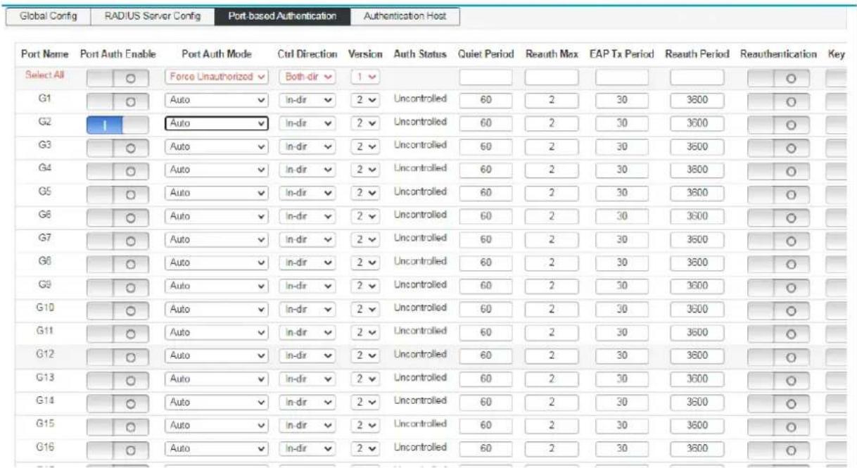
| Authentication enable: | Enable the port and configure the 802.1X authentication status of the port. |
| Port: | Displays switch port number |
| Control mode: | Select the control mode for this port:Automatic: the port needs to be authenticated. Forced Certified: port can access the network without authentication.Forced Non-Certified: the port will never pass the authentication. |
| Certification status: | Display this port authorization status. |
| Silent time: | Fill in the silence time. After the user authentication fails, the 802.1X authentication request of the same user is no longer processed in the silent time. |
| Re-authentication times: | Fill in the maximum number of retransmissions for authentication. |
| EAP transmission Cycle : | Fill in the time of EAP transmission. |
| Re-authentication cycle: | Fill in the time of the re-authentication cycle to enable or disable re-authentication |
6.9.4 Authentication Host
Click the "Layer 2 Configuration >> 802.1X Configuration >> Authentication Host" menu in the navigation tree to enter the "Authentication Host" interface, as shown in the figure below.

Chapter 7: Multicast Management
7.1 IGMP-snooping
IGMP snooping(Internet Group Management Protocol Snooping) is a multicast constraint mechanism that runs on Layer 2 devices to manage and control multicast groups.
The Layer 2 device running IGMP snooping analyzes the received IGMP messages and establishes a mapping relationship between the port and the MAC multicast address, and forwards the multicast data according to the mapping relationship.
IGMP frame listening process
The switch listens to IGMP messages exchanged between the host and the router to track multicast information and the ports it applies to. When the switch detects that the host sends an IGMP Report to the router, the switch adds the port to the multicast address table. When the switch detects the IGMP Leave message sent by the host, the router sends the packet. The specific group query message (Group-Specific Query) of the port, if there are other hosts that need the multicast, it will respond to the report message. If the router does not receive any response from the host, the switch will take the port from the multicast. Deleted in the address table. The router periodically sends an IGMP Query message. After receiving the query message, the switch deletes the port from the multicast table if it does not receive the report message from the host within a certain period of time.
As shown in the following figure, when Layer 2 devices are not running IGMP snooping, multicast data is broadcast on Layer 2; when Layer 2 devices are running IGMP Snooping, multicast data of known multicast groups is not on Layer 2. It is broadcast and is multicast to the designated receiver at Layer 2, but unknown multicast data will still be broadcast at Layer 2.
![graph TD A["Source"] --> B["Router"] B --> C["Layer 2 switch"] C --> D["Host A Receiver"] C --> E["Host B"] C --> F["Host C Receiver"] B --> G["Multicast router"] style A fill:#000,stroke:#000,color:#fff style B fill:#000,stroke:#000,color:#fff style C fill:#000,stroke:#000,color:#fff style D fill:#…](/content/2026/08/1621927/images/830432c5e2ae467e806c641821d8dc0654210e2139c6e8176d03b83777721bde.jpg)
![graph TD Source --> MulticastRouter["Multicast router"] MulticastRouter --> Layer2Switch["Layer 2 switch"] Layer2Switch --> HostA["Host A Receiver"] Layer2Switch --> HostB["Host B"] Layer2Switch --> HostC["Host C Receiver"] MulticastRouter -->|Data Flow| HostA MulticastRouter -->|Data Flow| HostB Mu…](/content/2026/08/1621927/images/958ae8281a052f78ff3483a23dd542c96062a0a490063d4a03f059a5eba96e8e.jpg)
7.1.1 IGMP-Snooping Global Configuration
Click "Layer 2 Management" >> "IGMP-Snooping" >> "IGMP-Snooping" in the navigation bar to enter the function interface, as shown below:

Enable Turn on/off IGMP-Snooping.
Host aging time When a member port joins a multicast group, the switch allocates a time to the port in the setting. If the switch does not receive the report packet sent by the member port. The member port is considered invalid.
7.1.2 IGMP-Snooping VLAN Configuration
The multicast group established by IGMP snooping is based on the VLAN broadcast domain. Different VLANs can be configured with different IGMP parameters. This page is used to configure the IGMP frame listening parameters for each VLAN.
Click "Layer 2 Management" >> "IGMP-Snooping" >> "IGMP-Snooping VLAN Configuration" in the navigation bar to enter the function interface, as shown below:

VLAN ID fill in the VLAN ID that enables IGMP frame listening.
Leave the multicast quickly When the port starts to leave the multicast function quickly, the switch directly receives the IGMP Leave message.
Remove from the multicast group.
Query message source address Enter the IP address of the query message source.
Query message interval Enter the query interval time, and the querier will send general query messages according to the interval.
Maximum response time Enter the value of the maximum response time field of the query message.
Last member query interval Enter the interval for querying multicast members.
Route aging time When routing a multicast group, the device allocates a time to the route. The device does not pass the set time.

Note
The fast leave function can take effect only when the host supports IGMPv2 or v3.
If the fast leave function is enabled at the same time as the "unknown multicast packet drop" function, if there are multiple users on a port and one user leaves quickly, it may cause multicast for other users in the same multicast group business disruption.
7.1.3 Static Multicast
Based on the previous multicast-on-demand mode, when users in different VLANs order the same multicast group, the data is replicated and forwarded on the multicast router for each VLAN that contains the receiver.
Such a multicast on-demand method wastes a lot of bandwidth. After the IGMP snooping function is enabled, the multicast VLAN is configured to add the port of the switch to the multicast VLAN. The users in different VLANs share a multicast VLAN to receive multicast data. The multicast stream is only in one multicast. Bandwidth is transmitted within the VLAN, saving bandwidth. And because of the multicast VLAN and the user. The VLAN is completely isolated, security and bandwidth are guaranteed.
Click "Layer 2 Management" >> "IGMP-Snooping" >> "Static Multicast" in the navigation bar to enter the function interface, as shown below:

VLAN ID Fill in the VLAN ID of the multicast VLAN.
Multicast source Fill in the IP address of the multicast source server.
Multicast Address Fill in the IP address of the multicast server, which must be a multicast address.
Port list Select the port to be added to the multicast group.

Note
After static multicast is established, all IGMP messages are processed only in static multicast groups

Description
Multicast address.
According to the IANA (Internet Assigned Numbers Authority), the IP address of a multicast packet uses a class D IP address, and the multicast IP address ranges from 224.0.0.0 to 239.255.255.255. The scope and description of several special multicast IP address segments are as follows:
| Multicast address range | Remark |
| 224.0.0.0 - 224.0.0.255 | Reserved address of routing protocols and other underlying topology discovery and maintenance protocols |
| 224.0.1.0 - 224.0.1.255 | Conference and video conferencing. That is, a public multicast address that can be used on the Internet. |
| 239.0.0.0 - 239.255.255.255 | The address inside the LAN is used, and you cannot use the Internet. |
Multicast MAC address
IANA stipulates that the upper 24 bits of the multicast MAC address start with 01-00-5E, and the lower 23 bits are the lower 23 bits of the multicast IP address.
The reason why most of the multicast addresses start with 01-80-C2 and 01-00-5E, because the protocols that use these multicast addresses are under the name of IEEE and IANA, their OUI are 00-80-C2 and 00-00-5E, the multicast addresses are 01-80-C2 and 01-00-5E. Of course, in addition to these multicast addresses occupied by the leading brother, there are 01-00-0C- Address such as CC-CC-CC, this address is occupied by Cisco, Cisco's OUI is 00-00-0C
7.2 MLD Snooping
MLD Snooping (Multicast Listener Discovery Snooping MLD) is an IPv6 multicast restriction mechanism running on a switch, used to manage and control IPv6 multicast groups. Enabling the MLD snooping function can effectively prevent multicast data from being broadcast on the network.
7.2.1 MLD Snooping Global Configuration
Click "Layer 2 Management" >> "Multicast Management" >> MLD-Snooping >> in the navigation bar to enter the MLD-Snooping global configuration interface, as shown below:

Enable Turn on/off MLD-Snooping function
Host aging time When a member port joins a multicast group, the switch will allocate a time for the port. In the set time, if the switch does not receive the report message sent by the member port. The member port is considered invalid.
7.2.2 MLD-Snooping VLAN configuration
The multicast group established by IGMP snooping is based on the VLAN broadcast domain and different IGMP parameters can be set for different VLANs. This page is used to configure IGMP frame listening parameters for each VLAN.
Click "Layer 2 Management" >> Multicast Management >> "IGMP-Snooping" >> "IGMP-Snooping VLAN Configuration" in the navigation bar to enter the function interface, as shown below:

VLAN ID Fill in the VLAN ID for enabling IGMP frame listening function.
Quick leave multicast When the port starts the fast leave multicast function, when the switch receives an IGMP leave message, it will delete the port from the multicast group.
Query message source address Enter the IP address of the query message source.
Query message interval Enter the query interval time and the querier will send general query messages according to the interval time.
Maximum response time Enter the maximum response time field value of the query message.
Last member query interval Enter the interval time for multicast member query.
Route aging time When a route is connected to a multicast group, the device will allocate a time to the route and set it within the set time. If the device does not receive a query message from the router port, it considers that the router port is invalid.
7.2.3 IPv6 static multicast
Based on the previous multicast on-demand method, when users in different VLANs request the same multicast group, the data will be replicated and forwarded on the multicast router for each VLAN containing the receiver. Such a multicast on-demand method wastes a lot of bandwidth. After the IGMP Snooping function is activated, the port of the switch is added to the multicast VLAN by configuring the multicast VLAN, so that users in different VLANs share a multicast VLAN to receive multicast data, and the multicast stream is only in one multicast VLAN. Transmission is carried out within the VLAN, thereby saving bandwidth. And because of multicast VLAN and users. VLAN is completely isolated, security and bandwidth are guaranteed.
Click "Layer 2 Management" >> Multicast Management >> "MLD-Snooping" >> "IPv6 Static Multicast" in the navigation bar to enter the function interface, as shown below:

VLAN ID Fill in the VLAN ID of the multicast VLAN.
Multicast source Fill in the IP address of the multicast source server.
Multicast address Fill in the IP address of the multicast server, which must be a multicast address.
Port list Select the port that needs to join the multicast group.

Note:
When static multicast is established, all IGMP messages are only processed in the static multicast group.
Chapter 8: Advanced Settings
8.1 QOS Configuration
The QoS (Quality of Service) function is used to improve the reliability of network transmission and provide a high-quality network service experience. In a traditional IP network, all packets are treated in the same way without distinction. The network sends the packets with the best effort (Best-Effort), but does not guarantee any performance such as delay and reliability.
Along with the rapid development of network technology and multimedia technology, IP networks are increasingly carrying interactive multimedia communication services such as video conferencing, distance learning, and video on demand based on existing services such as www, FTP, and E-mail. Videophones, etc., and each service requires different transmission delays, variable delays, throughput, and packet loss rates. Therefore, providing different quality of service (QoS) for various services of users has become an important challenge for the development of the Internet.
The so-called QoS is for different needs of various network applications, and provides different quality of service, such as providing dedicated bandwidth, reducing packet loss rate, and reducing packet transmission delay and delay jitter. That is to say, in the case that the bandwidth is not sufficient, the contradiction between the bandwidth occupied by various service flows is balanced.
QoS working principle
The switch classifies the data streams in the ingress phase, and then maps different types of data streams to queues of different priorities in the export phase, and finally determines the manner in which the packets of different priority queues are forwarded according to the scheduling mode, thereby realizing the QoS function.
![graph LR A["Message sent to this interface"] --> B["Message classification"] B --> C["Messages are mapped to different priority queues"] C --> D["Queue scheduling"] D --> E["Forwarded message"] E --> F["Export"] style A fill:#f9f,stroke:#333 style B fill:#ccf,stroke:#333 style C fill:#cfc,stroke:#33…](/content/2026/08/1621927/images/5b253fd618996b4b3980937b5ba2f7147d86d850f8c7a091ad2266e2869e2596.jpg)
8-1 QoS working principle
Message classification: Objects are identified according to certain matching rules.
Mapping: Users can map packets entering the switch to different priority queues according to the priority mode. The switch provides three priority modes: port-based priority, 802.1P/COS priority, and DSCP priority.
Queue scheduling: When the network is congested, it must solve the problem of multiple data streams competing for resources at the same time, usually solved by queue scheduling.
The switch provides four scheduling modes: strict priority mode (SP), weighted Round Robin mode (WRR), Round Robin mode (RR), and weighted fair queue mode (WFQ).
Scheduling mode
When the network is congested, queue scheduling is usually used to solve the problem that multiple data streams compete for resources at the same time. The switch implements a total of eight scheduling queues—TC0 to TC7. TCO corresponds to the lowest priority queue, and TC7 corresponds to the highest priority queue. At the same time, the switch provides four scheduling modes, namely strict priority mode (SP), weighted Round Robin (WRR), RR mode, and weighted, Weighted Fair Queue (WFQ).
- SP-Mode: Strict priority mode. The scheduling mode of the SP mode is that the switch preferentially forwards the data frame with the highest priority at the current priority. After all the highest priority data frames are forwarded, the data frames of the next highest priority are forwarded. The switch has eight egress queues, which in turn are TC0-TC7. In SP queue mode, their priorities are increased in turn, and TC7 has the highest priority. The disadvantage of the SP queue is that if there is a packet in the higher priority queue for a long time when congestion occurs, the packet in the low priority queue will "starve" due to lack of service.
![graph LR A["Message sent to this interface"] --> B["Message classification"] B --> C["SP-Mode Queue scheduling"] C --> D["High priority"] D --> E["The packets of queue TC3 are forwarded first"] C --> F["TC3"] C --> G["TC2"] C --> H["TC1"] C --> I["TC0"] D --> J["Export"]](/content/2026/08/1621927/images/1fdf3a9558a3f4b553692abf0ad1b3eedb21e1a163b1fcab4f35a0c036e57fe2.jpg)
8-4 Strict priority mode
- WRR-Mode: WRR priority mode. The WRR mode scheduling algorithm performs round scheduling between queues according to the weight ratio to ensure that each queue receives a certain service time. The weighted value indicates the proportion of the acquired resource. The WRR queue avoids the disadvantage that packets in low priority may not be served for a long time when using SP scheduling, and although multiple queue scheduling is performed by round, it is not a fixed allocation service time for each queue. If the queue is empty, the next queue schedule will be replaced immediately, so that the bandwidth resources can be fully utilized. The default weight ratio of TC0-TC7 is 1:2:4:8:16:32:64:127.
![graph LR A["Message sent to this interface"] --> B["Message classification"] B --> C["TC0-TC3 packets in the four queues are forwarded according to the ratio of 1:2:4:8"] C --> D["WRR-Mode Queue scheduling"] D --> E["Export"] style A fill:#f9f,stroke:#333 style B fill:#ccf,stroke:#333 style C fill:#…](/content/2026/08/1621927/images/51d99bf96ae389965fbc7e29e718f0dae1c205fd0b1480c5a93b9f622577d832.jpg)
8-5WRR Priority mode
- RR-Mode: Round-Robin mode, A strategy for channel scheduling in communication that allows users to use shared resources in turn without considering instantaneous channel conditions. From the perspective that the same number of radio resources (same scheduling time period) are allocated to each communication link, the
Round-Robin can be regarded as fair scheduling. However, Round-Robin is unfair from the perspective of providing the same quality of service to all communication links, in which case more radio resources must be allocated for communication links with poor channel conditions (more time). In addition, since the Round-Robin does not consider the instantaneous channel conditions during the scheduling process, it will result in lower overall system performance, but a more balanced quality of service between the various communication links than the maximum carrier-to-interference ratio scheduling.
- WFQ-Mode: Weighted fair queue mode. WFQ is a complex queuing process that guarantees fairness between the same priority and weights between different priorities. The number of queues can be pre-configured and the range is (16-4096).
WFQ, embody weight on the basis of guaranteeing fairness (bandwidth, delay), the weight value depends on the IP precedence (Precedence) carried in the JP packet header. WFQ classifies packets by flow (same source IP address, destination IP address, source port number, destination port number, protocol number, Precedence messages belong to the same stream) Each stream is assigned to a queue. This process is called hashing. The WFQ enrollment process is automatically completed using the HASH algorithm, and different streams are divided into different queues as much as possible. At the time of dequeuing, WFQ allocates the bandwidth of each stream to the outlet according to the priority of the stream. The smaller the value of the priority, the less bandwidth is obtained. The larger the value of the priority, the more bandwidth is obtained. This ensures fairness between the same priority services and reflects the weight between different priority services. For example, there are currently 8 streams in the interface, and their priorities are O, 2, 2, 3, 4, 5, 6, and 7. The total quota for the bandwidth will be: the sum of all (the priority of the stream + 1). Namely:
1+3+3+4+5+6+7+8=37
The ratio of bandwidth occupied by each stream is: (its own priority number + 1), (the sum of all (stream priority +1)). That is, the available bandwidth for each stream is: 1/37, 3/37, 3/37, 4/37, 5/37, 5/37, 6/37, 7/37, 8/37.
It can be seen that WFQ reflects the weight of different priority services on the basis of ensuring fairness, and the weight depends on the IP priority carried in the IP packet header.
8.1.1 Global configuration
When the network is congested, the problem that multiple packets compete for resources at the same time must be solved. Usually, queue scheduling is used to solve the problem. Congestion management generally uses queue scheduling techniques to avoid intermittent congestion in the network. Queue scheduling techniques are: SP
(Strict-Priority, strict priority queue). WFQ (Weighted Fair Queue, Weighted fair queue) and WRR (Weighted Round Robin, Weighted polling queue). RR (Round Robin, Cyclic scheduling)
Configure interface scheduling type operation steps
- Click in the navigation tree "Advanced Settings >> QOS Configuration >> Global Configuration" menu, enter the "Scheduling Policy" interface, as shown below.

Scheduling mode configuration
SP-Mode: Strict priority mode. In this mode, the high-priority queue occupies the entire bandwidth. Only after the high-priority queue is empty, the low-priority queue forwards the data. WRR-Mode: Weighted polling priority mode. The WRR queue scheduling algorithm performs round-robin scheduling between queues to ensure that each queue receives a certain service time. Taking a port with 8 output queues as an example, WRR can configure a weight value for each queue. (The weighting values corresponding to queue7 - queue0 are w7, w6, w5, w4, w3, w2, w1, w0)
RR-Mode: The scheduling policy allows users to use shared resources in turn, regardless of instantaneous channel conditions. Since polling scheduling does not consider instantaneous channel conditions during the scheduling process, it will result in lower overall system performance. However, compared with the maximum carrier-to-interference ratio scheduling, there is a more balanced quality of service between communication links.
WFQ-Mode: Weighted fair queue mode. Users can use WFQ's queue
scheduling algorithm to specify the bandwidth for each queue in the 0 to 7 queue.
Then according to the CoS value of each stream and the mapping relationship of the queue, which stream is into which queue, and which bandwidth is divided.
Queue weight value:
Enter the weight value for the 8 queues. When RR and SP modes are selected, weight value configuration is not allowed.
COS queue mapping operation steps
- Click in the navigation tree "Advanced Settings >> QOS Configuration >> Global Configuration" menu, enter the "COS Queue Mapping" interface, as shown below.

Interface meaning as follows:
| Configuration item | Instructions |
| Cos | Range 0-7 |
| Queue | Range 0-7 |
DSCP Queue mapping steps
Click in the navigation tree"Advanced Settings >> QOS Configuration >> Global Configuration" menu, enter the "COS Queue Mapping" interface, as shown below.
| Maps to new DSCP & CoS based on the DSCP in packet IP header. By default, DSCP & CoS Mapping are not changed. | |
| DSCP-CoS Map | DSCP 0 → New DSCP 0 → CoS 0 Set |
| 0->0->0 1->1->0 2->2->0 3->3->0 4->4->0 5->5->0 6->6->0 7->7->0 | |
| 8->8->1 9->9->1 10->10->11->11->11->112->12->113->13->114->115->115->1 | |
| 15->16->217->17->218->18->219->19->220->20->221->21->222->223->223->2 | |
| 24->24->225->25->226->236->237->27->238->28->239->29->230->30->31->31->3 | |
| DSCP-CoS Map | 32->32->43->33->44->34->45->35->46->36->47->37->48->38->49->39->4 |
| 40->40->51->41->512->42->53->43->54->44->55->45->56->46->57->47->5 | |
| 48->48->69->49->60->50->61->51->62->52->63->53->64->54->65->56->6 | |
| 50->50->77->57->78->58->79-9 -> 70-9 -> 60 -> 71 -> 61 -> 72 -> 62 -> 73 -> 63 -> 7 | |
Priority
DSCP: The DSCP priority of the packet, with a priority level of 0 to 63.
NEW DSCP: The NEW DSCP priority of the packet, with a priority level of 0 to 63.
COS: Corresponding to different levels of priority queues. Expressed as COS0, COS1 ... COS7.
8.1.2 Port management
Port management steps
- Click in the navigation tree"Advanced Settings>> QOS Configuration>> Port Management" menu, enter the "Port Management" interface, click "Settings" to complete the configuration, as shown below
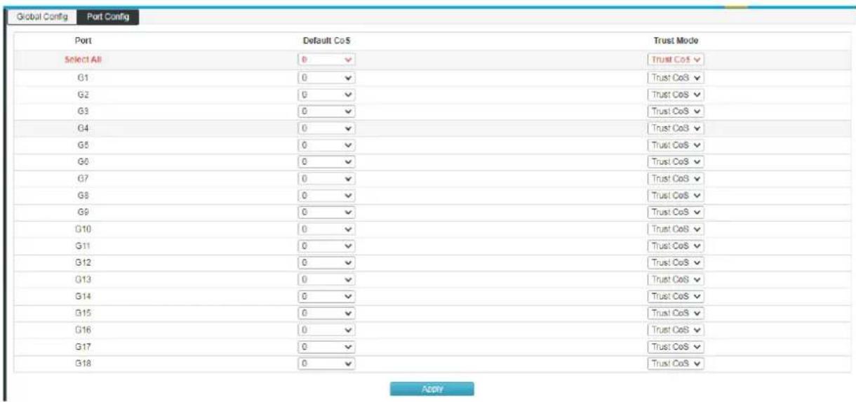
Port priority configuration
Port: Physical port of the switch.
Priority: Configure the priority level of the port.
8.2 ACL Configuration
With the expansion of network scale and the increase of traffic, the control of network security and the allocation of bandwidth become an important part of network management. By filtering packets, you can effectively prevent unauthorized users from accessing the network. You can also control traffic and save network resources. ACL (Access Control List) is used to implement packet filtering by configuring matching rules and processing operations on packets.
After receiving the packet, the port of the switch analyzes the field of the packet according to the ACL rule applied to the current port. After the specific packet is identified, the corresponding packet is allowed or disabled according to the preset policy.
The packet matching rule defined by the ACL can also be referenced by other functions that need to distinguish the traffic, such as the definition of the traffic classification rule in the QoS.
By setting matching rules and operation processing, an access control list (ACL) can implement packet filtering. An access control list is a collection of series of license and rejection conditions that apply to a packet. When receiving a packet on the interface, the switch determines that the packet is permitted to be forwarded based on the criteria specified in the access list compared to the ACL used. The ACL classifies packets by a series of matching conditions, such as the source MAC address, destination MAC address, source IP address, destination IP address, and port number of the packet. The ACL classifies packets by a series of matching conditions, such as the source address, destination address, and port number of the packet. ACLs can be divided into the following categories depending on the purpose of the application:
Basic IP ACL: Rules are formulated based only on the source IP address of the packet. ACL ID range: 100 - 999.
Advanced IP ACL: The rules are based on Layer 3 and Layer 4 information such as the source IP address, destination IP address, protocol type of the IP bearer, and protocol features. ACL ID range: 100-999.
MAC ACL (MAC ACL): Rules are formulated based on Layer 2 information such as the source MAC address, destination MAC address, VLAN priority, and Layer 2 protocol type of the data packet. ACL ID range: 1-32.
8.2.1 TIME RANGE Configuration
The configuration of the effective time range allows the user to control the ACL of packets based on the time range.
The time period is used to describe a particular time range. Users may have such requirements: some ACL rules need to be valid for one or some specific time, while they are not used for packet filtering in other time periods, which is commonly referred to as filtering by time period. At this time, the user can configure one or more time periods first, and then reference the time period when configuring the ACL rule, thereby implementing time-based ACL filtering.
The configuration of the time period has the following contents: a configuration period time period and an absolute time period. The configuration period time period is in the form of a weekly day of the week; the configuration absolute time period takes the form from the start time to the end time.
Operating steps
Click in the navigation "Advanced Settings>> ACL Configuration>> TIME RANGE Configuration" menu, enter the "TIME RANGE Configuration" interface, as shown below.

Add Time Range
Time period name: Fill in the name of the time period to make it easy to distinguish the information of each time period.
Absolute time: Configure the absolute time mode of the time period. Only when the system date is in absolute time, the ACL rule based on the time period can take effect.
Cycle: Configure the periodic mode of the time period. Only when the system date is within the cycle time, the ACL rule based on the time period can take effect.
Start time: Configure the start time of the time segment in the time
period.
End Time: Configure the end time of the time segment in the time period.
Time Range List
Name: Displays the time period name.
Status: Displays the status of the time period.
Time: Displays the configured time period.
Delete: Delete the time period.
8.2.2 MAC ACL Configuration
MAC ACL: Rules are formulated based on Layer 2 information such as source MAC address, destination MAC address, VLAN priority, and Layer 2 protocol type.
Operating steps:
- Click in the navigation tree Advanced Settings >> ACL Configuration >> MAC ALC Configuration menu is displayed. The MAC ALC Configuration interface is displayed, as shown in the following figure.

MAC ACL
Access Control List ID: Select the ACL ID to be configured.
| Rule ID: | Fill in the rule ID. |
| Security Operation: | Select how the switch handles packets that meet the matching rules.The default is allowed.Allow: Forward packets.Discard: Drops the packet. |
| Source MAC: | Fill in the source MAC address information contained in the rule. |
| Source MAC Mask: | Fill in the source MAC address mask. |
| Destination MAC: | Fill in the destination MAC address information contained in the rule. |
| Destination MAC Mask: | Fill in the destination MAC address mask. |
| Time-Range Name: | Select the name of the rule time period. The default is unlimited. |
2. Fill in the appropriate configuration items.

3. Click 'Add 'to complete the configuration as shown
| Entry ID | Rule ID | Action | Source MAC | Destination MAC | Time Range | |
| 1 | 1 | deny | 74-57-54-74-57-45/ft-ft-ft-ft-ft | e5-64-64-58-45-64/ft-ft-ft-ft-ft-ft | 545 | Del |
8.2.3 IP ACL configuration
Basic IP ACL: According to the IP address information of the data packet, a matching rule is formulated, the data packet is analyzed and processed accordingly.
Advanced IP ACL: According to the source IP address information, destination IP address information of the message, the protocol type carried by the IP, the characteristics of the protocol and other information, the matching rules are formulated, the data packets are analyzed and processed accordingly.
Operating steps:
- Click in the navigation tree Advanced Settings >> ACL Configuration >> IP ALC Configuration menu is displayed. The IP ALC Configuration interface is displayed, as shown in the following figure.

Expansion IP ACL
Access control list Select the ACL ID you want to configure.
ID
Rule ID: Fill in the rule ID.
Safe operation:: Select how the switch handles packets that meet the matching rules. The default is allowed.
- Allow: Forward packets.
- Discard: Drops the packet.
Source IP: Fill in the source IP address information contained in the rule.
Source mask: Fill in the source IP address mask.
Destination IP: Fill in the destination IP address information contained in the rule.
Destination mask: Fill in the destination IP address mask.
Protocol: Select the IP protocol information contained in the rule.
Source port When the IP protocol selects TCP/UDP, the TCP/UDP source port number included
number: in the rule is configured here.
Destination port When the IP protocol selects TCP/UDP, the TCP/UDP destination port number
number: included in the rule is configured here.
Time period: Select the time period name for the rule takes effect
2. Fill in the corresponding configuration parameters

3. Click"add", Complete configuration, as shown below:
| Entry ID | Rule ID | Action | Protocol | Source IP | Source mask | Source Port | Destination IP | Purpose mask | Destination Port | Time-Range | |
| 2 | 4 | deny | icmp | 192.168.88.123 | 255.255.255.255 | 192.168.88.1 | 255.255.255.255 | 546 | Del | ||
| 3 | 3 | deny | jmp | any | any | any | any | 546 | Del | ||
| 4 | 5 | deny | top | any | any | any | any | Del | |||
| 10 | 7 | deny | udp | any | any | any | any | Del |
8.2.4 ACL GROUP Configuration
After you've created the list, you'll have to apply it to every interface you want to use.
Operation Steps:
- Click Advanced Settings>>ACL configuration>>ACL GROUP configuration menu in the navigation tree, then go to the ACL GROUP Configuration interface, as the picture shows:
| MAC ACL CONFIG | IP ACL CONFIG | Time Range Config | ACL GROUP CONFIG | |
| Port | G1 - G1 | |||
| MAC ACL | Is blank, indicating that the rules applied to delete the port (if any exist) | |||
| IP ACL | Is blank, indicating that the rules applied to delete the port (if any exist) | |||
| Set | ||||
| Port | MAC access list ID | IP access list ID | ||
| G1 | ||||
| G2 | ||||
| G3 | ||||
| G4 | ||||
| G5 | ||||
| G6 | ||||
| G7 | ||||
| G8 | ||||
| G9 | ||||
| G10 | ||||
| G11 | ||||
| G12 | ||||
| G13 | ||||
| G14 | ||||
| G15 | ||||
| G16 | ||||
| G17 | ||||
| G18 | ||||
ACL GROUP Configuration
MAC access list ID Select the created MAC address list ID and apply it to the port.
IP access list ID: Select the created IP access list ID to apply to the port.
- Fill in the corresponding configuration item, Take acl 1 and acl 10 as examples, apply to G1-G2 and G3-G4 respectively.
- Click "Settings" to complete configuration, as the picture shows

8.3 SNMP Configuration
SNMP Overview
SNMP (Simple Network Management Protocol) is the most widely network management protocol in UDP/IP networks, It provides a management framework to monitor and maintain Internet devices. SNMP structure simple and easy to use, it can shield physical differences between different devices to achieve automatic management of different devices. Most network management systems and platforms are based on SNMP. The biggest advantage of SNMP is that simple design. It does not require complicated implementation process, also, it does not take up too much network resources, easy to use. The basic functions of SNMP include monitoring network performance, detecting and analyzing network errors, and configuring network devices. When the network is working properly, SNMP can be achieved statistics, configuration and testing functions; When the network fails, it can implement various error detection and recovery.
SNMP management framework
SNMP system includes NMS (Network Management System). Agent. Management object and MIB (Management Information Base)
NMS as the network management center of the whole network to manage devices.
Each managed device contains an Agent process, MIB, and multiple managed objects residing on the device. The NMS interacts with the Agent running on the managed device, then the Agent completes the NMS command by operating the MIB of the device.
SNMP management model
![graph TD A["NMS"] <--> B["Agent"] B <--> C["MIB"] C <--> D["Management object"] style A fill:#f9f,stroke:#333 style B fill:#ccf,stroke:#333 style C fill:#cfc,stroke:#333 style D fill:#fcc,stroke:#333](/content/2026/08/1621927/images/cfd22ba76a43886f2424c5e807894322c2414ec1996f72d66b3e57b09628016f.jpg)
NMS
NMS play a manage role in the network, using SNMP is a protocol for network equipment management / monitoring systems, running on the NMS server. The NMS can issue a request to the Agent on the device to query or modify one or more specific parameter values. The NMS can receive the trap information sent by the agent on the device to learn the current status of the managed device.
Agent
The Agent is an agent process in the managed device for maintaining the information data of the managed device and reporting the management data to the NMS that sent the request in response to the request from the NMS. After receiving the request information of the NMS, the Agent completes the corresponding instruction through the MIB table, and responds the operation result to the NMS. When equipment failure or other event occurs, the device will automatically send information to the Agent NMS, to change the current state of the NMS reporting device.
Management object
Management object refers to the managed object. Each device may contain multiple managed objects. The managed object may be some hardware in the device (such as an interface board), or it may be a collection of hardware, software (such as routing protocol) and its configuration parameters.
MIB
MIB is a database that indicates the variables are maintained by managed devices (ie, can be Agent query and set information). The MIB defines a set of attributes of the managed device in the database: the name of the object, the state of the object, the access rights of the object, and the data type of the object. Through the MIB, the following functions can be completed: The agent can obtain the current status information of the device by querying the MIB.
The Agent can set the status parameters of the device by modifying the MIB.
SNMP Protocol version
This switch provides SNMPv3 management functions and is compatible with SNMPv1 and SNMPv2c. the SNMP management version and the SNMP agent version need to be consistent. They can communicate with each other. You can select different security level management modes according to your application requirements.
SNMPv1: adopt community name certification. The community name is used to define the relationship between the SNMP manager and the SNMP agent. If the community name carried in the SNMP packet is not recognized by
the device, the packet will be discarded. Community name acts like a password to limit access to SNMP manager SNMP agent.
SNMPv2c: adopt community name certification. It is compatible with SNMPv1 and extends the functionality of SNMPv1.
SNMPv3: SNMPv3 greatly enhances security and user controllability based on the first two versions v1 and v2c. It adopt VACM (View-based Access Control Model) and USM (User-Based Security Model) authentication mechanism. The user can set the authentication and encryption functions. The authentication is used to verify the validity of the sender of the message and avoid the access of the illegal user. The encryption is to encrypt the transmission message between the SNMP manager and the SNMP agent to avoid eavesdropping. With the combination of features such as authentication and encryption, you can provide greater security for communication between SNMP managers and SNMP agents.
8.3.1 System Information
- Click the Advanced Settings > SNMP Configuration menu in the navigation tree to enter the System Information interface, as the picture shows

SNMP system configuration
Pattern: Selectable, Open or Disable
Version: Unselectable, The default SNMP device supports three versions, namely SNMPv1, SNMPv2c and SNMPv3
Name Fill in system name
Location Fill in location information
Contact: Fill in the contact information
Trap configuration
Enable: selectable, enable or disable, Trap is managed device without a request, sends information to the NMS, for reporting of critical and important events (such as the managed device restarts, etc.) please note that must be completed before configuring the basic functions of SNMP Trap basic configuration.
8.4 RMON Configuration
RMON (Remote Monitoring) is based on the SNMP architecture and is a standard monitoring specification proposed by the Internet Engineering Task Force (IETF). It enables SNMP to monitor remote devices more effectively and proactively. With the RMON function, the NMS can quickly track faults on the network, network segment or device, and take preventive measures to prevent network resources from failing. At the same time, RMON MIB can also record network performance, fault data and can access historical data at any time for effective fault diagnosis. RMON reduces the communication traffic between SNMP managers and agents, enabling network administrators to manage large networks simply and efficiently.
RMON working principle
The RMON agent stores network information in the RMON MIB. After the switch is placed in the RMON agent, it has the function of RMON detection. The administrator uses the basic commands of SNMP to exchange data information with the RMON agent to collect network management information. However, due to the limitation of device resources, the administrator cannot obtain all the data of the RMON MIB. Generally, only four groups of information can be collected. The four groups are: history group, event group, statistics group and alarm group.
RMON Group
This switch supports historical groups, event groups, statistics groups and alarm groups as defined in the RMON specification (RFC1757).
| RMON group | function | element |
| Historical groups | Network statistics are collected periodically and stored for later retrieval to effectively monitor the network. | Sampling port, interval, creator |
| Event groups | Define the event number and how the event is handled. The events defined here are primarily used for events generated by an alert trigger in an alert group. | Event description, event type, creator, username |
| Statistics groups | Monitor the statistical value of the alarm variable at the specified port. | Drop data packets, drop bytes, data packet transmission, broadcast data packets, multicast data packets, CRC error frames, too small (or oversized) data packets, collision frames, and packets of the following length: 64, 65-127, 128-255, 256-511, 512-1023 and 1024-10240 bytes. |
| Alarm groups | The specified alarm variables are monitored periodically and an alarm is triggered once the counter exceeds the threshold. | Alert variable, sample type, time interval, upper threshold, lower threshold, alarm trigger. |
8.4.1 Event Group
This page is used to configure the event group for RMON.
How to enter the page: Advanced Settings >> RMON >> Event Group

Sequence No.: Displays the Sequence No. of the event entry.
Description: Fill in the description of the event.
Type: Select the type of event
None: no need operation.
Log: The event is recorded in the switch and read by the SNMP management software.
Trap: Send an alert message to the management host.
Log&Trap: The event is logged in the switch and an alert message is sent to the management host.
8.4.2 Statistical Group
This page is used to configure the statistics group for RMON.
How to enter the page: Advanced Settings >> RMON >> Statistics Group

Statistics group configuration
Sequence No.:
Fill in the ID No. of the statistical entry, ranging from 1-65535.
Port:
Fill in or select the Ethernet port to be counted.
8.4.3 History Group
This page is used to configure the statistics group of RMON.
How to enter the page: Advanced Settings >> RMON>>History Group
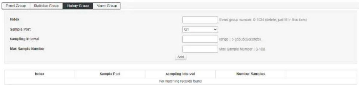
Sequence No.:
Displays the Sequence No. of the sample entry.
Sampling Port:
Select the Port to sampling.
Sampling interval:
Fill in the interval for port sampling. Default is 1800 seconds.
Max No. of Sampling interval:
Displays the maximum number of sampling data entries that can be saved by the current history control entry. The range is 1-100 and the default is 50.
8.4.3 Alarm group
This page is used to configure the statistics group of RMON.
The steps to enter the page: Advanced Settings >> RMON >> Alarm Group

| Serial number | Displays the sequence number of the alarm entry. |
| Sampling port | Select the alarm port |
| Alarm specification | Select alarm variable |
| Sampling interval | The interval at which the alarm is filled out. The default is 1800 seconds |
| Sample type | Select the method for sampling the alarm variable and compare the sampled value to the threshold.absolute: Compares the sampled results directly to the threshold at the end of a sampling period.delta: The increment after subtracting the current value from the current value is compared to the threshold. |
| Rising threshold | Fill in the rising threshold that triggered the alert. The default is 100 |
| Rising event | Select the sequence number of the event that triggered the rising threshold alarm. |
| Fall threshold | Fill in the fall threshold that triggered the alert. The default is 100. |
| Falling Event | Select the sequence number of the event that triggered the falling threshold alarm. |
8.5 LLDP Configuration
LLDP (Link Layer Discovery Protocol) is a Layer 2 protocol that allows network devices to periodically advertise their own device information to neighboring devices in a local area network that conforms to the IEEE 802 standard. LLDP organizes the device identification, performance, and configuration information into different TLVs (Type/Length/Value) according to the IEEE802.1AB standard and is encapsulated in the Link Layer Discovery Protocol Data Unit (LLDPDU). The discovery protocol data unit is advertised to the neighbor device. After receiving the information, the neighbor device saves it in the form of a standard MIB (Management Information Base). The network management system can obtain this information through the Management Protocol SNMP (Simple Network Management Protocol) to query and judge the communication status of the link. In order to describe the physical topology of the network and related systems in the topology, the Internet Engineering Task Force (IETF) has proposed a standard MIB, and some companies have proposed private MIBs. However, IEEE 802 LAN sites do not have a uniform standard for transmitting MIB information. LLDP solves this problem. The LLDP protocol allows network devices of different vendors to work together. Devices running LLDP can automatically detect and learn information about neighbor devices. LLDP can also enable systems running different network layer protocols to learn each other's device information from each other. SNMP applications can use the information obtained by LLDP to perform network troubleshooting to improve network stability and maintain correct network topology.
LLDPDU
Each LLD PDU carries four mandatory TLVs and one or more optional TLVs. As shown in the figure below, Chassis ID TLV, Port ID TLV, TTL TLV and End TLV are the four TLVs that must be carried in each LLDPDU. The optional TLVs are determined by the network management system and provide detailed information about the local LLDP devices.

M - mandatory TLV - required for all LLDPDUs
The maximum length of an LLDPDU is determined by the specific transmission rate and the maximum message length allowed by the protocol. As far as the IEEE 802.3 MAC protocol is concerned, the maximum length of the LLD PDU is the maximum length of the basic MAC frame without TAG, that is, 1500 bytes.
LLDP Working Mechanism
1) LLDP Operating mode
Each port can be configured with the LLDPDU receiving and sending functions, so that the port can be configured with four working modes:
Send and receive: Both send and receive LLDPDUs.
Receive only: The received LLDPDUs are processed only, and the LLDPDUs are not sent out.
Send only: Sends LLDPDUs only, but does not process received LLDPDUs.
Disabled: The LLDPDU is not sent out or the received LLDPDU is processed.
2) LLDPDU Transmission mechanism
When the port works in the transmit-receive mode or the transmit-only mode, the device periodically sends an LLDPDU to the neighbor device to advertise its own information.
When the local device changes, the device sends a change notification. When the local device changes frequently in a short period of time, the NMS (Network Management System) will set a packet transmission delay to ensure that the LLDPDU is sent. A fixed minimum time difference.
When the working mode of a port is disabled or only the receiving mode is switched to the sending or receiving mode or the sending mode only, the fast start mechanism of the device is activated. The interval for sending packets becomes 1 s. After some LLDPDUs are quickly sent, the device recovers. Normal send cycle.
3) LLDPDU Receiving mechanism
When the port works in the transmit-receive mode or the receive-only mode, the device checks the validity of the received LLDP packets and the TLVs they carry. After checking, the neighbor information is saved locally and is based on TTL (Time To Live). The value of the TTL in the TLV is used to set the aging time of the neighbor information on the local device. If the value is zero, the neighbor information is aged out.
TLV
The TLV is the basic unit of the LLDPDU and is short for Type/Length/Value, that is, type/length/value. The format of the basic TLV is shown below,

The type of each TLV is different. According to the type of TLV, the type of information in the TLV can be judged. The following table is a detailed description of the various TLVs currently defined.
| TLV type | TLV name | Description | Whether must carry |
| 0 | End of LLDPDU | Identify the LLDPDU End. Any information after the End Of LLDPDU TLV will be discarded. | YES |
| 1 | Chassis ID | Identify the Chassis ID of the connected device | YES |
| 2 | Port ID | Identify ID information of sending port | YES |
| 3 | Time To Live | Aging time of local device information on neighboring devices | YES |
| 4 | Port description | Port description specified by the IEEE 802 LAN workstation used to issue this port to the neighbor | NO |
| 5 | system name | The system name used to publish the local device to the neighbor | NO |
| 6 | System specification | Description of the system information used to publish the local device to the neighbor,including the system hardware and software version. | NO |
| 7 | System capability | Used to publish to neighbors the features supported by the local device and whether they are allowed | NO |
| 8 | Management address | Used to advertise the management address of the local device to the neighbor. The network management protocol can manage the local device through the address. | NO |
| 127 | Organizational definition | Allows different organizations, software, and device manufacturers to define TLVs that send information to neighboring devices | NO |
TLVs generally include two categories, basic TLVs and organizationally defined TLVs.
1) Basic TLV
Basic TLVs are essential to implement the LLDP protocol, and they contain basic information about network management.
2) Organizationally defined TLV
Different organizations define many different TLVs. The port VLAN ID, protocol VLAN ID, VLAN name, and protocol identifier TLV are all defined by IEEE 802.1. The MAC/PHY configuration/status, power supply capability, link aggregation, and maximum frame length TLV are defined by IEEE 802.3.
Note

more details on TLV, please refer to the IEEE 802.1AB standard.
8.5.1 Global Configuration
To configure LLDP on a switch, you need to configure the global LLDP function and related parameters on the page.
How to enter the page: Advanced Settings >> LLDP >> Global Config

LLDP function: Choose whether to enable LLDP.
Packet sending period: Configure the time interval at which the local device sends LLDPDUs to neighboring devices.
Delay:
Configure the delay for the local device to send LLDPDUs to neighbors. When the local configuration changes, the LLDPDUs are sent to the neighbor device for a specified time to prevent continuously transmission of LLDPDUs as frequent local configuration changes
Device information save multiple:
The device information save multiple is used to control the value of the TTL field in the LLDPDU sent by the local device. The TTL is the lifetime of the local information on the neighbor device TTL=TTL multiplier* transmission interval.
Initialization delay:
When the port LLDP working mode is changed, it will be delayed for a period of time and then initialized to prevent the port from continuously initialization as frequent changes LLDP working mode.
Management address:
Management address of the device: the default is 192.168.254.1
8.5.2 Port configuration
On this page you can configure the receiving and sending of all ports.
Enter the page: Advanced Settings >> LLDP Configuration >> Port Configuration

8.5.3 LLDP Port configuration
On this page, you can view the LLDP information of the equipment adjacent to the machine
How to enter the page: Advanced Settings>>LLDP Configuration>>LLDP Neighbor

8.6 NTP configuration
This page is used to configure the system time of the switch. The system time is the time used by the switch to work. The time information in other functions (such as access control) is subject to this. You can also choose Synchronize Local Time in the global configuration to obtain the current management PC time as the system time of the switch.
8.6.1 NTP Global configuration
On this page you can set NTP global information.
Enter the page: Advanced Settings >> NTP Configuration >> NTP Global Configuration

Mode: Set the NTP service to be turned on and off.
Time zone setting: Select the time zone where the switch time synchronization location is located
Time gap: Time calibration period, default is 300s
8.6.2 NTP server configuration
You can manually configure the NTP server address in this page
How to enter the page: Advanced Settings >> NTP Configuration >> NTP Server Configuration

Server Select to increase the server address
Common server Common NTP server address recommendation

Note: If the time request from the specified time server is unsuccessful, the switch will select the server
address that successfully obtained the time last time and the default public time server address on the network to obtain the time (the switch needs to be connected to the Internet).
8.7 Anti-attack
The anti-attack module provides several security measures for protecting the security of the LAN, including the DDOS module and the Icmp-echo module.
DDOS
DDoS (Distributed Denial of Service) Distributed denial of service attack refers to the use of client/server technology to combine multiple computers as an attack platform to launch DDoS attacks on one or more targets, thereby multiplying the power of denial of service attacks. Typically, an attacker uses a theft account to install the DDoS host program on a computer. At a set time, the master program communicates with a number of agents that have been installed on many computers on the network. The agent launches an attack when it receives an instruction. With client/server technology, the master can activate hundreds or thousands of agents in seconds.
ICMP
ICMP (Internet Control Message Protocol) is a sub-protocol of the TCP/IP protocol suite for passing control messages between IP hosts and routers. The control message refers to the network itself, such as the network is unreachable, the host is reachable, and the route is available. ICMP protocol is extremely important for network security. The characteristics of the ICMP protocol itself make it very easy to be used to attack routers and hosts on the network. It can use the operating system to specify the maximum size of ICMP packets not exceeding 64KB, and launch "Ping of Death" to the host. Ping) attack. The principle of the "Ping of Death" attack is: if the size of the ICMP packet exceeds the 64KB limit, the host will have a memory allocation error, causing the TCP/IP stack to crash, causing the host to crash, and in addition, to the target host for a long time, continuous, Sending ICMP packets in large quantities will eventually make the system paralyzed. A large number of ICMP packets will form an "ICMP storm", which makes the target host consume a lot of CPU resources and is exhausted.

DDOS select whether to enable the DDOS protection function of the switch
ICMP-echo select whether to enable the switch's ICMP anti-ping function
Chapter 9: System Management
9.1 User settings
This page is used to configure the identity type of the user who logs in to the switch web page. Unless otherwise noted in this specification, Web pages are at the "Administrator" login prevelege.
How to enter the page: System Settings >> User Management

Administrator account: You can edit, modify and view the configuration of each function of the switch
Password: Fill in the login password.
Confirm password: Enter the login password again. The new entered passwords must match.
9.2 Network settings
This page is used to configure the management IP address for logging in to the switch. VLAN IP also can be set as the management address in the Layer3 switch. Devices in different VLANs can log in to the switch through VLAN IP for management.
9.2.1 IPv4 configuration
How to enter the page: System Settings>>Network Settings>>IPv4 Configuration

IP address
Set the IP address of the switch. The default is 192.168.254.1. You can modify this value according to the actual network. The address switch can be passed inside the LAN. Subnet mask: Set the subnet mask of the switch. The default is 24, which can be modified according to the actual network conditions.
Default gateway
When you need to connect the switch to the Internet, you need to set the default gateway of the switch. You can fill in the current network default gateway according to the actual network conditions.
Preferred DNS server When the switch needs to access the domain name or communicate with the domain name address, you need to set the DNS service server of the switch. You can fill in the current network DNS server address according to the actual network conditions.
Alternate DNS server Alternate DNS server, the current network can be filled according to the actual network alternate DNS server.
9.2.2 IPv6 configuration
How to enter the page: System Settings>>Network Settings>>IPv6 Configuration

| IP address | Set the IP address of the switch. The default is fe80::fe01. You can modify this value according to the actual network. The address switch can be passed inside the LAN.Subnet mask: Set the subnet mask of the switch. The default is 64, which can be modified according to the actual network conditions. |
| Default gateway | When you need to connect the switch to the Internet, you need to set the default gateway of the switch. You can fill in the current network default gateway according to the actual network conditions. |
9.3 Alarm Configuration
The alarm function is to enhance the alarm reporting reminder of the user management switch.
- How to enter the page: System Settings>>Alarm Configuration

- Select the corresponding configuration item, as shown in the figure.

- View the alarm list after operating according to the alarm conditions, as shown in the figure.
| Alarm Config Alarm List | ||||||||
| ☐ | Index | System Time | Log Level | Type | Module | Param | Log Content | |
| ☐ | 1 | 2020-07-20 14:55:29 | alert | Link | PORT | G6 | Interface [G6] state change to up. | Unprocessed |
| ☐ | 2 | 2020-07-20 14:55:27 | alert | Link | PORT | G6 | Interface [G6] state change to down. | Unprocessed |
| ☐ | 3 | 2020-07-20 14:55:25 | alert | Link | PORT | G14 | Interface [G14] state change to up. | Unprocessed |
| ☐ | 4 | 2020-07-20 14:55:23 | alert | Link | PORT | G14 | Interface [G14] state change to down. | Unprocessed |
| ☐ | 5 | 2020-07-20 14:55:21 | alert | Link | PORT | G6 | Interface [G6] state change to up. | Unprocessed |
| ☐ | 6 | 2020-07-20 14:55:17 | alert | PoE | POE | G6 | Interface [G6] poe disconnect. | Unprocessed |
| ☐ | 7 | 2020-07-20 14:55:16 | alert | Link | PORT | G6 | Interface [G6] state change to down. | Unprocessed |
9.4 Service configuration
The service configuration function is to configure the corresponding port for different remote login modes to enhance the security of the user management switch.
This feature includes TELNET configuration, SSH configuration and HTTP configuration 3 configuration options.
How to enter the page: System Settings >> Service Configuration

9.4.1 TELNET service
This page is used to enable or disable Telnet on the switch.
TELNET port If the port number changes from default 23, make sure to specify the custom port number when using the Telnet command.
Format: Telnet 192.168.254.1 xx (xx is the port number)

9.4.2 SSH service
SSH (Secure Shell) is a security protocol developed by the Internet Engineering Task Force (IETF) based on the application layer and transport layer. SSH encrypted connection provides functionality similar to a telnet connection, but the traditional telnet remote management, in essence, is unsafe, because it is on the network using clear text passwords and data transmission, people with ulterior motives can easily intercepted These passwords and data. When remotely logging into a device through a network environment that cannot guarantee security, the SSH function can provide strong encryption and authentication security. It can encrypt all transmitted data and can effectively prevent information leakage during remote management. SSH is composed of server and client, and there are two incompatible versions of V1 and V2. During the communication process, the SSH server and the client automatically negotiate the SSH version number and the encryption algorithm. After the agreement is reached, the client initiates an authentication request for login to the server. After the authentication is passed, the two parties can exchange information. The switch supports the SSH server function. You can use the SSH client software to log in to the switch through SSH. SSH key import is to import the SSH public
key file into the switch. If the key is successfully imported, the switch will use the key authentication method to accept SSH login.
SSH service option can choose whether to enable SSH function. The default protocol version is SSH v2.
SSH port Configure the SSH login port. The default is 22.
9.4.3 HTTP service
The service provides three protocol options: HTTP, HTTPS, HTTP & HTTPS. The default is http. You can manually select HTTPS and HTTP&HTTPS. When the protocol is HTTPS, the format of the WEB interface is
https://192.168.254.1. When the protocol is selected as HTTP&HTTPS, the user can choose any login mode!

Entry introduction:
HTTP protocol:
HTTP (HyperText Transfer Protocol) allows users to manage switches on the browser. The HTTP standard is the result of a collaborative study between the Internet Engineering Task Force and the World Wide Web Consortium. This item can be configured to enable and disable HTTP function.
HTTP port The default port is 80, which can be modified according to your requirements. After modifying, you need to specify the custom port number in the URL. The format is 192.168.254.1:xx (xx is the custom port number).
HTTPS protocol
SSL (Secure Sockets Layer) is a secure protocol that provides secure connections for TCP-based application layer protocols, such as providing a more secure HTTPS connection for normal HTTP connections. The SSL protocol is widely used for identity authentication and encrypted data transmission between Web browsers and servers. It is used in e-commerce, online banking and other fields to provide security for data communication on the network.
The services provided by the SSL protocol mainly include:
- Perform certificate-based authentication on users and servers to ensure that data is sent to the correct users and servers;
- Encrypt the transmitted data to prevent the data from being stolen in the middle;
- Maintain data integrity and ensure that data is not altered during transmission.
SSL uses asymmetric encryption technology to encrypt/decrypt data using a "key pair" consisting of a public key (contained in the certificate) and a private key. Initially, the switch already has a default certificate (self-signed) and a corresponding private key. The default key pair can also be replaced by the certificate/key import function, but the SSL certificate/key must be paired and imported, otherwise HTTPS cannot be connected normally.
After the function is enabled, you can log in to the web page of the switch through https://192.168.254.1. When you log in to the switch through HTTPS for the first time to using the default certificate of the switch, the browser may prompt "The certificate is self-signed without being trusted" or "Certificate error". In this case, please add this certificate as a trusted certificate, or continue browsing the website.
HTTP port The default port is 443, which can be modified according to your requirements. After modifying, you need to specify the custom port number in the URL. The format is 192.168.254.1:xx (xx is the custom port number).
9.5 Configuration management
9.5.1 Reset configuration
With a software reset, the switch can be restored to factory settings and all configuration data will be cleared.
How to enter the page: System Settings >> Configuration Management


Note: After the software is reset, the switch configuration will be restored to the factory default state
and the configured data will be lost.
9.5.2 Upload configuration
Upload configuration is to import the previously backed up configuration file to the switch to restore the switch to the current configuration state.
How to enter the page: System Settings>>Configuration Management
Upload Config
Select...
Upload

Note:
It may take a long time to restore the configuration. During this period, please be patient and do not operate the switch.
The power of the switch cannot be turned off during the process of importing the configuration file, otherwise the switch will be damaged and unusable.
After importing the configuration file, the original configuration information in the switch will be lost. If the imported configuration file is wrong, it may cause the switch to be unmanageable.
9.5.3 Download configuration
The download configuration function is to package the current configuration information of the switch into a file and save it to the PC, so that the configuration can be restored through the file in the future.
How to enter the page: System Settings>>Configuration Management
Download Config
Download

Note:
It may take a long time to back up the current configuration. During this period, please be patient and do not operate the switch.
9.6 Firmware upgrade
The switch can upgrade system files through the Web. After the system is upgraded, it will get more complete functions.
How to enter the page: System Settings >> Firmware Management
Product Model
Hardware Version
Firmware Version
Compile Time
New Firmware File


Note:
Firmware upgrade can only be done using firmware designed for the specific model.
It is recommended to back up configuration information before upgrading.
When upgrading, please select the firmware that is consistent with the hardware version of the switch. The upgrade process will take a while, do not powered off during the process, otherwise the device can be damaged.
9.7 Diagnostic Test
The switch provides three diagnostic methods: Ping detection, Tracert detection, and network cable detection.
9.7.1 Ping detection
The ping detection function can detect whether the switch and a network device are reachable, and it is convenient for the network administrator to check the connectivity of the network and locate the network fault.
The Ping detection process is as follows:
1) The switch sends an ICMP request message to the target device.
2) If there is network connectivity, the target device returns an ICMP response packet to the switch after receiving the packet; displaying related statistics.
3) If there is no network connection, the source device will display information such as the destination address unreachable or timeout.
How to enter the page: Series Settings >> Diagnostic Test >> Ping Detection

9.7.2 Tracert test
Tracert detection can view the router through which the switch passes to the target node. Use this command to analyze a failed network node when the network fails.
A TTL field is included in the IP packet header. When the packet is forwarded in the network, the value of each route TTL field is decremented by one. When the TTL field of the received IP packet is 0 or 1, the router discards the packet and replies an ICMP timeout message to the source. This effectively prevents packets from flowing endlessly in the network in the event of a network failure.
The Tracert detection process is as follows:
1) The switch sends a packet with a TTL of 1 to the destination device.
2) The first hop (that is, the first router that the packet arrives) responds with a TTL timeout ICMP packet (the packet contains the IP address of the first hop), so that the switch obtains the first router address.
3) The switch resends a packet with a TTL of 2 to the destination device.
4) The second hop responds with a TTL timeout ICMP message, so that the switch gets the address of the second router.
5) Repeat the above process until the destination device is finally reached, and the switch gets the address of all routers that pass through it to the destination device.
Enter the page: System Settings >> Diagnostic Test >> Tracert Test

9.7.3 Network cable detection
The cable detection function can detect whether the cable connected to the switch is faulty or the fault location.
This function can be used to assist in daily engineering installation diagnosis.
Enter the page: System Maintenance >> System Diagnostics >> Cable Detection
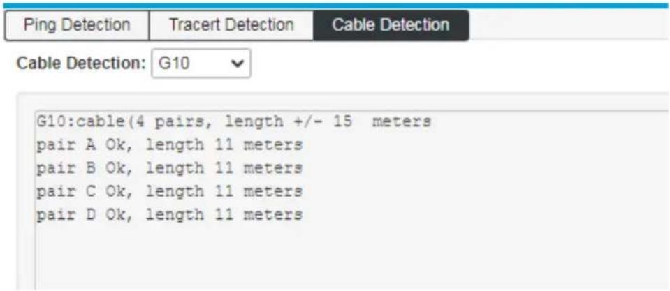
Cable Detection: Select the port to be cable tested.
Pair: Shows the pair number.
Status: Possible states are: Normal, Open.
Open circuit: There is disconnection on the line. The reasons for this situation are poor cable contact at the other end.
Detection failure - there may be situations that the line does not support detection.
Length: If the link is active, the approximate cable length is displayed.

Note:
Before or after the diagnosis of the same port, please wait for more than 3 seconds.
When the cable is longer, the diagnosis result will be more accurate.
The length here refers to the length of the cable pair, not the length of the cable run. The length is approximate.
9.8 Restart the system
Here you can reboot the switch and automatically return to the login page after the switch restarts. Save the current configuration before restarting. Otherwise, the unsaved configuration information will be lost.
How to enter the page: System Management >> Restart System
Restart System
Restart

Note: Do not turn off the power of the device during device restart to avoid device damage.
- WEB UI REFERENCE GUIDE
- TABLE OF CONTENTS
- CHAPTER 1: OVERVIEW
- CHAPTER 2 PRODUCT INTRODUCTION
- CHAPTER 3: MANAGING SWITCHES
- CHAPTER 4: PORT MANAGEMENT
- CHAPTER 5: POE MANAGEMENT
- CHAPTER 9: SYSTEM MANAGEMENT
- TARGET AUDIENCE
- BOOK CONVENTION
- CHAPTER 2: PRODUCT INTRODUCTION
- PRODUCT INTRODUCTION
- FRONT PANEL
- INDICATORS
- RJ45 PORTS
- SFP PORTS
- RST BUTTON
- CONSOLE PORT
- SIDE PANEL
- POWERING THE SWITCH
- GROUNDING THE SWITCH
- INTERFACE FUNCTION LIST
- WEB LOGIN
- WEB INTERFACE COMPOSITION
- GLOBAL INFORMATION
- STATEMENT
- TRAFFIC STATISTICS
- LOG INFORMATION
- LOG LIST
- NOTE
- EXPORT LOG FILE
- PORT CONFIGURATION
- STATE
- SPEED
- DUPLEX
- RATE CONFIGURATION
- MAXIMUM FRAME LENGTH
- FLOW CONTROL
- ENABLED
- PORT ISOLATION
- SELECT ALL
- DESCRIPTION
- PORT MIRRORING
- MIRROR TARGET PORT
- PORT MANAGEMENT
- MIRROR DIRECTION
- PORT SPEED LIMIT
- INGRESS RATE
- EGRESS RATE
- STORM CONTROL
- BROADCAST (PPS)
- MULTICAST (PPS)
- UNKNOWN UNICAST (PPS)
- GLOBAL CONFIGURATION
- PORT ENERGY SAVING
- PORT POE MANAGEMENT
- MAXIMUM POWER
- DEVICE POWER SUPPLY
- MAXIMUM TOTAL POWER SUPPLY
- TIMING POWER SUPPLY CONFIGURATION
- TIME PERIOD CONFIGURATION
- ADD TIME RANGE
- CONFIGURATION TIME
- POWER OFF PERIOD
- TIMING POWER SUPPLY
- INTELLIGENT POWER SUPPLY CONFIGURATION
- INTELLIGENT POWER SUPPLY
- ZERO FLOW DURATION
- CHAPTER 6: LAYER 2 MANAGEMENT
- MAC ADDRESS TABLE
- ADD
- DELETE
- LEASE TIME REMAINING
- VLAN CONFIGURATION
- VLAN STATE
- PORT
- VLAN
- VLAN MODES
- PVID
- CONFIGURATION EXAMPLE
- VOICEVLAN CONFIGURATION
- ENABLE VOICE VLAN
- VLAN ID
- COS
- DSCP
- MAC
- MAC MASK
- MAC VLAN CONFIGURATION
- IP VLAN CONFIGURATION
- IP
- GVRP
- GARP INTRODUCTION
- GVRP INTRODUCTION
- GVRP CONFIGURATION STEPS
- LINK AGGREGATION
- STATIC LINK CONFIGURATION
- LOAD BALANCING MODE
- DYNAMIC AGGREGATION CONFIGURATION
- SYSTEM PRIORITY
- ACTIVITY MODE
- PORT PRIORITY
- KEY VALUE
- SWITCH
- LINK AGGREGATION INFORMATION
- MSTP CONFIGURATION
- INSTANCE CONFIGURATION
- PORT INSTANCE CONFIGURATION
- SPANNING TREE NETWORKING EXAMPLE
- TOPOLOGY OVERVIEW
- OPERATION STEPS
- ERPS CONFIGURATION
- ERPS RING AND RING TYPE
- NODE ROLE AND PORT ROLE
- ERPS INSTANCE AND LOAD BALANCING
- ERPS PROTOCOL MESSAGE
- MESSAGE TYPES INCLUDE
- SF (SIGNAL FAIL) MESSAGE
- MS (MANUAL SWITCH) MESSAGE
- FS (FORCED SWITCH) MESSAGE
- FLUSH MESSAGE
- VIRTUAL CHANNEL AND NON-VIRTUAL CHANNEL
- ERPS AGREEMENT STATUS
- ERPS WORKFLOW
- LINK DOWN PROTECTION SWITCHING
- LINK RECOVERY AND SWITCHBACK
- SWITCHBACK MECHANISM AND MANUAL CONFIGURATION
- MANUAL CONFIGURATION INCLUDES
- MANUAL SWITCH (MS)
- FORCED SWITCH (FS)
- CLEAR
- ERPS PROFILE CONFIGURATION
- ERPS RING CONFIGURATION
- ERPS EXAMPLE CONFIGURATION
- ROLE PORT
- ERPS SUB-RING INSTANCE CONFIGURATION
- ERPS RING INSTANCE INFORMATION
- STATUS INFORMATION OF THE RING INSTANCE
- STATUS INFORMATION OF THE INTERFACE
- LOOP PROTECTION
- ENABLE START LOOP PROTECTION
- DHCP-SNOOPING
- STATIC BINDING
- X CONFIGURATION
- X ARCHITECTURE
- X AUTHENTICATION MECHANISM
- X AUTHENTICATION PROCESS
- EAP RELAY MODE
- EAP TERMINATION METHOD
- X TIMER
- CONFIGURATION
- X FUNCTIONAL SWITCH
- RADIUS SERVER SHARED PASSWORD
- RADIUS SERVER RETRANSMISSIONS
- RADIUS SERVER TIMEOUT
- RADIUS SERVER DEATH TIME
- RADIUS SERVER SETTINGS
- PORT-BASED AUTHENTICATION
- AUTHENTICATION HOST
- CHAPTER 7: MULTICAST MANAGEMENT
- IGMP-SNOOPING
- IGMP FRAME LISTENING PROCESS
- IGMP-SNOOPING GLOBAL CONFIGURATION
- IGMP-SNOOPING VLAN CONFIGURATION
- STATIC MULTICAST
- MULTICAST ADDRESS
- MULTICAST MAC ADDRESS
- MLD SNOOPING
- MLD SNOOPING GLOBAL CONFIGURATION
- MLD-SNOOPING VLAN CONFIGURATION
- IPV6 STATIC MULTICAST
- CHAPTER 8: ADVANCED SETTINGS
- QOS CONFIGURATION
- QOS WORKING PRINCIPLE
- SCHEDULING MODE
- SCHEDULING MODE CONFIGURATION
- QUEUE WEIGHT VALUE
- COS QUEUE MAPPING OPERATION STEPS
- PRIORITY
- ACL CONFIGURATION
- TIME RANGE CONFIGURATION
- OPERATING STEPS
- TIME RANGE LIST
- MAC ACL CONFIGURATION
- MAC ACL
- FILL IN THE APPROPRIATE CONFIGURATION ITEMS
- CLICK 'ADD 'TO COMPLETE THE CONFIGURATION AS SHOWN
- IP ACL CONFIGURATION
- EXPANSION IP ACL
- FILL IN THE CORRESPONDING CONFIGURATION PARAMETERS
- CLICK"ADD", COMPLETE CONFIGURATION, AS SHOWN BELOW
- ACL GROUP CONFIGURATION
- SNMP CONFIGURATION
- SNMP OVERVIEW
- SNMP MANAGEMENT FRAMEWORK
- SNMP MANAGEMENT MODEL
- NMS
- AGENT
- MANAGEMENT OBJECT
- MIB
- SNMP PROTOCOL VERSION
- SYSTEM INFORMATION
- SNMP SYSTEM CONFIGURATION
- TRAP CONFIGURATION
- RMON CONFIGURATION
- RMON WORKING PRINCIPLE
- RMON GROUP
- EVENT GROUP
- STATISTICAL GROUP
- STATISTICS GROUP CONFIGURATION
- HISTORY GROUP
- ALARM GROUP
- LLDP CONFIGURATION
- LLDPDU
- LLDP WORKING MECHANISM
- LLDP OPERATING MODE
- LLDPDU TRANSMISSION MECHANISM
- LLDPDU RECEIVING MECHANISM
- TLV
- BASIC TLV
- ORGANIZATIONALLY DEFINED TLV
- DELAY
- DEVICE INFORMATION SAVE MULTIPLE
- INITIALIZATION DELAY
- MANAGEMENT ADDRESS
- LLDP PORT CONFIGURATION
- NTP CONFIGURATION
- NTP GLOBAL CONFIGURATION
- NTP SERVER CONFIGURATION
- ANTI-ATTACK
- DDOS
- ICMP
- USER SETTINGS
- NETWORK SETTINGS
- IPV4 CONFIGURATION
- IPV6 CONFIGURATION
- ALARM CONFIGURATION
- SERVICE CONFIGURATION
- TELNET SERVICE
- SSH SERVICE
- HTTP SERVICE
- ENTRY INTRODUCTION
- HTTP PROTOCOL
- HTTPS PROTOCOL
- CONFIGURATION MANAGEMENT
- RESET CONFIGURATION
- UPLOAD CONFIGURATION
- DOWNLOAD CONFIGURATION
- FIRMWARE UPGRADE
- DIAGNOSTIC TEST
- PING DETECTION
- TRACERT TEST
- NETWORK CABLE DETECTION
- RESTART THE SYSTEM
Brand : D-LINK
Model : DIS-F200G-10PS-E
Category : Uncategorized