ZISS480DMSS - Refrigerator Monogram - Free user manual and instructions
Find the device manual for free ZISS480DMSS Monogram in PDF.



| Brand | Monogram |
| Model | ZISS480DMSS |
| Product Type | Built-in Refrigerator |
| Installation Type | Built-in / Integrated |
| Width | 48 inches (121.9 cm) |
| Height | 84 inches (213.4 cm) |
| Depth | 24 inches (61 cm) counter-depth |
| Total Capacity | Approx. 20.4 cu. ft. |
| Cooling System | Multi-zone frost-free |
| Temperature Control | Digital electronic with separate refrigerator and freezer zones |
| Water Dispenser | External filtered water dispenser |
| Ice Maker | Automatic in-door ice maker with ice and water dispenser |
| Shelves | Adjustable spill-proof glass shelves |
| Lighting | LED interior lighting |
| Door Alarm | Yes, alerts when door is ajar |
| Energy Efficiency | ENERGY STAR certified |
| Noise Level | Whisper quiet operation |
| Defrost | Automatic defrost |
| Power Supply | 115V, 60Hz, 15A |
| Warranty | 2-year limited warranty |
| Spare Parts Availability | Genuine Monogram parts available online |
| Maintenance | Regular condenser coil cleaning recommended |
| Safety Features | Child lock control panel and door alarm |
Frequently Asked Questions - ZISS480DMSS Monogram
User questions about ZISS480DMSS Monogram
0 question about this device. Answer the ones you know or ask your own.
Ask a new question about this device
Download the instructions for your Refrigerator in PDF format for free! Find your manual ZISS480DMSS - Monogram and take your electronic device back in hand. On this page are published all the documents necessary for the use of your device. ZISS480DMSS by Monogram.
USER MANUAL ZISS480DMSS Monogram
Installation Instructions
If you have questions, call 800.626.2000 or visit our website at: www.monogram.com
Side by Side Refrigerators
ZIS360N, ZISB360D, ZISW360D
ZISS360N, ZISS360D
ZIS420N, ZISB420D, ZISW420D
ZISS420N, ZISS420D
ZIS480N, ZISB480D, ZISW480D
ZISS480N, ZISS480D
Design Guide
With Installation Instructions
BEFORE YOU BEGIN
Read these instructions completely and carefully.
- IMPORTANT - Save these instructions for local inspector's use. Observe all governing codes and ordinances.
- Note to Installer - Be sure to leave these instructions with the Consumer.
- Note to Consumer - Keep these instructions with your Owner's Manual for future reference.
WARNING:
This appliance must be properly grounded. See "Grounding the Refrigerator," page 10.
AVERTISSEMENT
If you received a damaged refrigerator, you should immediately contact your dealer or builder.
CAUTION:
Due to the weight and size of this refrigerator, and to reduce the risk of personal injury or damage to the product – THREE PEOPLE ARE REQUIRED FOR PROPER INSTALLATION OF A 36" WIDE UNIT. FOUR PEOPLE ARE REQUIRED FOR INSTALLATION OF A 42" OR 48" WIDE MODEL.
PRUDENCE
Skill Level - Installation of this refrigerator requires basic mechanical, carpentry and plumbing skills. Proper installation is the responsibility of the installer. Product failure due to improper installation is not covered under the GE Appliance Warranty. See the Owner's Manual for warranty information.
WARNING:
- These refrigerators are top-heavy and must be secured to prevent the possibility of tipping forward. Anti-Tip protection is required. See page 12 for details.
- Use this appliance only for its intended purpose.
- Immediately repair or replace electric service cords that become frayed or damaged.
- Unplug the refrigerator before cleaning or making repairs.
- Repairs should be made by a qualified service technician.
AVERTISSEMENT
For Monogram service in Canada 1-888-880-3030
For Monogram Parts and Accessories, call 1-800-626-2002.
www.monogram.com
CONTENTS
Planning Guide
The Installation Space ....3
Dimensions and Clearances ....3
130° Door Swing 4
90° Door Swing ....5
Customization Basics 6
1/4" Framed Panel Dimensions ....7
3/4" Overlay Panel Dimensions ....8
Raised Overlay Panel Design 9
Side Panels....10
Installation Instructions
Tools, Hardware, Materials ....10
Grounding the Refrigerator ....10
Step 1, Remove Packaging ....11
Step 2, Install Water Line ....11
Step 2A, RO Water Line ....12
Step 3, Install Side Panels ....12
Step 4, Install Anti-Tip Brackets .....12
Step 5, Level Refrigerator ....13
Step 6, Secure Refrigerator to Cabinetry ..13
Step 7, Adjust Door Swing ....13
Step 8, Install Grille Panel .....14
Step 9, Install Framed Panels ....15
Step 9A, Install Overlay Panels ....16
Step 10, Install Dispenser Trim .....17
Step 11, Connect Water Supply ....17
Step 12, Connect Power ....18
Step 13, Start Icemaker ....18
Step 14, Install Toekick ....18
THE INSTALLATION SPACE

*The finished cutout width must be:
35-1/2" for 36" models
41-1/2" for 42" models
47-1/2" for 48" models
Water And Electrical Locations
The opening must be prepared with the electrical and water supply located as shown.
The cutout depth must be 24"
The refrigerator will project forward, slightly beyond adjacent cabinetry, depending on your installation.
Cutout depth beneath a soffit:
When installed beneath a soffit, the soffit cannot exceed the 24" installation depth shown. The top case trim overlaps the bottom of the soffit.
Additional Specifications
- A 115 volt 60Hz., 15 or 20 amp power supply is required. An individual properly grounded branch circuit or circuit breaker is recommended. Install a properly grounded 3-prong electrical receptacle recessed into the back wall. Electrical must be located on rear wall as shown.
Note: GFI (ground fault interrupter) is not recommended.
- Water line can enter the opening through the floor or back wall. The water line should be 1/4" O.D. copper tubing or GE SmartConnect™ kit between the cold water line and water connection location, long enough to extend to the front of the refrigerator. Installation of an easily accessible shut off valve in the water line is required.
DIMENSIONS AND CLEARANCES

Product Clearances
These refrigerators are equipped with a 2 position door stop. The factory set 130° door swing can be adjusted to 90° if clearance to adjacent cabinets or walls is restricted.
90° Door Swing130° Door Swing

| Models A B C |
| 36" 13" 15" 20-5/8" |
| 42" 13" 19" 26-5/8" |
| 48" 15" 20" 28-5/8" |
Allow minimum clearances for freezer door (Dimension A) and fresh food door (Dimension B) for a full 130° door swing and to allow for pan removal.
4" minimum clearance is required when door swing is adjusted to 90°. If the 90° door stop position is used, pan access is maintained, but pan removal is restricted.
See illustrations pages 4 and 5 to determine door swing interaction with adjacent cabinets or countertops.
Design Guide

Design Guide

CUSTOMIZATION BASICS:
Framed Or Overlay Panels, Custom Handles and Accessory Kits
Stainless Steel Wrapped Models
36" wide models - ZISS360N, ZISS360D
42" wide models - ZISS420N, ZISS420D
48" wide models - ZISS480N, ZISS480D
Trimmed Models
36" wide models - ZIS360N, ZISB360D, ZISW360D
42" wide models - ZIS420N, ZISB420D, ZISW420D
48" wide models - ZIS480N, ZISB480D, ZISW480D
Stainless Steel Wrapped Refrigerators
Stainless Steel wrapped refrigerators have wrapped doors and grille panel, beveled edges, and tubular stainless steel handles that coordinate with other Monogram appliances. These models are shipped ready for installation.
Trimmed Refrigerators
Trimmed refrigerators are designed to be customized with decorative panels. Field installed custom door and grille panels are required.
Framed panels
You may install 1/4" thick custom panels from your cabinet manufacturer. The decorative panel slides into the factory installed trim. Or, order black, white and stainless steel accessory panels from your Monogram dealer.

Standard supplied handles shown in 1/4" panel position.
Optional Accessory Kits
ZKHSS2: Monogram Tubular Stainless Steel handles designed to fit 3/4" overlay panels.
Accessory Panels
White, black and stainless steel accessory panels are available from your Monogram dealer. Panels are cut to size and ready to install.
Overlay panels
You may also choose to install custom overlay panels from your cabinet manufacturer. This design provides a seamless appearance which integrates smoothly with surrounding cabinetry.

Standard supplied handles shown in 3/4" overlay panel position.
Door Handles
The standard supplied handles can be adjusted to accommodate both framed or overlay panels. Custom handles of your choice, supplied by your cabinet maker can also be installed on overlay panels. If desired, you may order ZKHSS2 Monogram stainless steel tubular handle kit for 3/4" overlay panels.
Side Panels
Side panels must be used whenever the sides of the refrigerator will be exposed.
Models White Black Stainless
Acrylic Acrylic Steel
| ZISW480D ZPW480D ZPS480D |
| ZISB480D ZPB480D ZPS480D |
| ZIS480N ZPW480N ZPB480N ZPS480N |
| ZISW420D ZPW420D ZPS420D |
| ZISB420D ZPB420D ZPS420D |
| ZIS420N ZPW420N ZPB420N ZPS420N |
| ZISW360D ZPW360D ZPS360D |
| ZISB360D ZPB360D ZPS360D |
| ZIS360N ZPW360N ZPB360N ZPS360N |
1/4" FRAMED PANEL DIMENSIONS
If you choose to install framed panels, they must be cut to the dimensions shown. The panels will slide into the frame on the door and grille.
Non-Dispenser Models
If the custom panel is less than 1/4" thick and it fits loosely in the door frame it can be backed up with a piece of filler material or foam tape to improve the fit.

IMPORTANT NOTE: Maximum total panel weight:
- Fresh food door panel – 75 lbs.
- Freezer door panel – 53 lbs.
- Grille Panel – 18 lbs.
IMPORTANT NOTE - Dispenser Models
The refrigerator is supplied with two dispenser trims, one for framed panels and one for overlay panels.
- If the panel is less than 0.250" thick a noticeable gap may be created around the dispenser trim. Foam tape may be applied on the door to improve the fit.
- If the panel is more than 0.250" thick, the dispenser trim cannot be secured to the door.
See Dispenser Trim Fit Example, page 9.


The framed panel must be 1/4" nominal thickness to fit the dispenser trim.
| Side-by-Side (in inches) | Dispenser Cutout Position | ||||
| A | B | C | D | E | |
| 36" Models 33-7/8 9 68-3/8 14-9/16 18-9/16 17-13/16 3-1/8 | |||||
| 42" Models 39-7/8 9-1/2 68-3/8 14-9/16 24-9/16 17-13/16 3-1/8 | |||||
| 48" Models 45-7/8 9-1/2 68-3/8 18-9/16 26-9/16 17-13/16 5-1/8 | |||||
3/4" OVERLAY PANEL DIMENSIONS
For a more custom appearance, overlay panels may be installed on trimmed models. The overlay panel must be secured to a 1/4" thick backer panel which slides into the trim. A spacer panel 0.10" thick must be placed between the overlay and backer panel.
Assemble the panels with glue and screws.
- Center the spacer panel on the backer panel, left to right and top to bottom. Secure the panels with glue.
- Center the spacer and backer panel on the overlay panel and secure with glue and screws. Screws must be countersunk into the backer panel.


NOTE: Left-to-right offset is not always equal to top-to-bottom offset.
.250" + .10" + .750" = 1.100" Total Panel Thickness
IMPORTANT NOTE – Dispenser Models
The refrigerator is supplied with two dispenser trims, one for framed panels and one for overlay panels. The overlay dispenser trim is designed to fit a total panel thickness of 1.100".
- If the panel is less than 1.100" a noticeable gap may be created around the dispenser trim.
- If the panel is more than 1.100" the dispenser trim cannot be secured to the door.
See Dispenser Trim Fit Example, page 9.
- The overlay panel must be constructed according to the specifications shown to achieve the correct total thickness.
- Alternative panel construction methods such as securing a 3/4" panel to a 1/4" backer panel cannot be used. Another method, routing a 3/4" thick panel on all sides cannot be used. These methods will not result in the required 1.100" panel thickness.
When a raised panel design is to be used, a custom middle rail is required. See page 9 for details.

Dispenser Cutout

*Cut the dispenser opening after the backer, spacer and overlay panels have been assembled.
IMPORTANT NOTE: Maximum total weight for the assembled panels:
- Fresh food door panel – 75 lbs.
- Freezer door panel – 53 lbs.
- Grille Panel – 18 lbs.
36" Side-by-Side (in inches)
| A | B | C | D | E | |||
| 1/4" Backer Panel | 33-7/8 | 9 68-3/8 | 14-9/16 | 18-9/16 | |||
| .10" Spacer Panel | 33 | 8-3/8 | 67 | 13-1/4 | 17-1/4 | ||
| 3/4" Overlay Panel | 34-1/8 | 9-1/4 | 68-5/8 | 14-13/16 | 18-13/16 | 17-15/16 | 3-1/4 |
42" Side-by-Side (in inches)
| A | B | C | D | E | F | ||
| 1/4" Backer Panel | 39-7/8 | 9-1/2 | 68-3/8 | 14-9/16 | 24-9/16 | ||
| .10" Spacer Panel | 39 | 8-5/8 | 67 | 13-1/4 | 23-1/4 | ||
| 3/4" Overlay Panel | 40-1/8 | 9-3/4 | 68-5/8 | 14-13/16 | 24-13/16 | 17-15/16 | 3-1/4 |
48" Side-by-Side (in inches)
| A | B | C | D | E | F | ||
| 1/4" Backer Panel | 45-7/8 | 9-1/2 | 68-3/8 | 18-9/16 | 26-9/16 | ||
| .10" Spacer Panel | 45 | 8-5/8 | 67 | 17-1/4 | 25-1/4 | ||
| 3/4" Overlay Panel | 46-1/8 | 9-3/4 | 68-5/8 | 18-13/16 | 26-13/16 | 17-15/16 | 5-1/4 |
DISPENSER MODELS: RAISED OVERLAY PANEL DESIGN
When a raised panel design is to be used, a custom wide middle rail is required to accept the dispenser trim.
- The middle rail must be wide enough to allow for the dispenser trim to overlap the opening.
- The middle rail must be 1.100" total thickness to accept the dispenser trim.

DISPENSER TRIM FIT EXAMPLES: (NOT TO SCALE)
1/4" FRAMED PANEL
- The dispenser trim fits over the custom panel and snaps into the freezer door.
- The clips will not engage the door if the panel is more than 0.250" thick.
- If the panel is less than 0.250" thick, a noticeable gap may be created around the dispenser trim.
3/4" OVERLAY PANEL
- The dispenser trim fits over the custom panel and snaps into the freezer door.
- The clips will not engage the door if the panel is more than 1.100" thick.
- If the panel is less than 1.100" thick, a noticeable gap may be created around the dispenser trim.


SIDE PANELS
Side panels must be used whenever the sides of the refrigerator will be exposed. The 1/4" side panels will slip into the side case trim. Secure the panels to the refrigerator with stick-on hook and loop fastener strips. Order the side panels from the cabinet manufacturer.
- Cut a notch in the top front corner as shown to allow clearance for corner keys in the front side trim.

* Depending on installation height.
TOOLS REQUIRED
• Tinsnips to cut banding
- Stepladder
- Bucket
- Level
• Appliance Hand Truck
- Tubing cutter
- 7/16" open-end wrench
• #2 Phillips screwdriver
- Drill and appropriate bits
- 5/16", 7/16" socket
- Safety glasses
• 1-1/4" open end wrench
- Pliers
- 1/4" ratchet wrench
HARDWARE SUPPLIED
• Water filter bypass plug
- Anti-Tip brackets
- 1/4" nut and ferrule
- Dispenser trims for 1/4" and 3/4" overlay panels
- 12 pan head screws for custom handle installation
MATERIALS REQUIRED
- 35" long 2x4 for Anti-Tip support
- 1/4" copper water line tubing or GE SmartConnect™ Refrigerator Tubing kits
• Water shut-off valve (optional but recommended) - Custom panels for doors and grille panel
- Screws to secure refrigerator to cabinetry
- Stick-on hook and loop fastener strips for 1/4" side panels
FLOORING
For proper installation, this refrigerator must be placed on a level surface of hard material that is at the same height as the rest of the flooring. This surface should be strong enough to support a fully loaded refrigerator, or approximately 1,500 lbs.
NOTE: Protect the finish of the flooring. Cut a large section of the cardboard carton and place under the refrigerator where you are working.
GROUNDING THE REFRIGERATOR
IMPORTANT - (Please read carefully)
FOR PERSONAL SAFETY, THIS APPLIANCE MUST BE PROPERLY GROUNDED.
The power cord of this appliance is equipped with a three-prong (grounding) plug which mates with a standard three-prong (grounding) wall receptacle to minimize the possibility of electric shock hazard from this appliance.
Have the wall outlet and circuit checked by a qualified electrician to make sure the outlet is properly grounded.
Where a standard 2-prong wall outlet is encountered, it is your personal responsibility and obligation to have it replaced with a properly grounded 3-prong wall outlet.
DO NOT, UNDER ANY CIRCUMSTANCES, CUT OR REMOVE THE THIRD (GROUND) PRONG FROM THE POWER CORD.
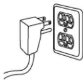
DO NOT USE AN ADAPTER PLUG TO CONNECT THE REFRIGERATOR TO A 2-PRONG OUTLET.
DO NOT USE AN EXTENSION CORD WITH THIS APPLIANCE.
STEP 1 REMOVE PACKAGING
CAUTION: Refrigerator is much heavier at the top than at the bottom – be careful when moving. When using a hand truck, handle from side only.
- Carefully cut banding at the top and bottom, remove outer carton.
- Slide out back corner posts (2).
- Slide carton off top of cabinet.
NOTE: IT IS NOT NECESSARY TO LAY CABINET DOWN IN ORDER TO REMOVE SKID!
- The unit is secured to the skid with 4 slotted tie-down straps. Remove the four 5/16" bolts from the base channels in the tie-downs.
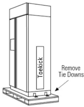
- Remove the four 7/16" bolts securing the straps to the skid.
CAUTION: DO NOT ATTEMPT TO ROLL UNIT OFF SKID.
PRUDENCE: IL NE FAUT PAS ESSAYER DE FAIRE ROULER LE RÉFRIGÉRATEUR POUR L'ENLEVER DE LAY PALETTE.
- Support blocks on the bottom of the refrigeration case must be removed before the refrigerator is taken off the skid or damage will occur. Carefully, tilt refrigerator and slide blocks out from beneath.
- Remove toekick, set aside for final installation.
- Lift the refrigerator off the skid with an appliance dolly. Handle from the sides.
STEP 2 INSTALL WATER LINE
- A cold water supply is required for automatic icemaker operation. The water pressure must be between 40 and 120 p.s.i.
- Route 1/4" OD copper or GE SmartConnect™ plastic tubing between house cold water line and the water connection location.
- Tubing should be long enough to extend to the front of the refrigerator. Allow enough tubing to accommodate bend leading into the water line connection.
NOTE: The only GE approved plastic tubing is supplied in the GE SmartConnect™ Refrigerator Tubing kits. Do not use any other plastic water supply line because the line is under pressure at all times. Other types of plastic may crack or rupture with age and cause water damage to your home.
GE SmartConnect™ Refrigerator Tubing Kits are available in the following lengths:
2' (.6 m) WX08X10002
6' (1.8 m) WX08X10006
15' (4.6 m) WX08X10015
25' (7.6 m) WX08X10025
Shut off the main water supply.
Turn on the nearest faucet long enough to clear the line of water.
- Install a shut-off valve between the icemaker water valve and cold water pipe in a basement or cabinet. The shut-off valve should be located where it will be easily accessible.

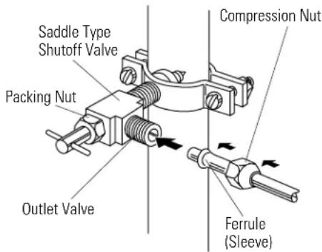
NOTE: It is best to install the valve into a vertical water pipe. If you install the valve into a horizontal water pipe, make the connection at the top or side, to avoid drawing off any sediment from the water pipe.
- Drill a 1/4" hole in the water pipe.
- Fasten the shut-off valve to the pipe with pipe clamp.
- Tighten the clamp screws until the sealing washer begins to swell. Do not over tighten.
- Place a compression nut and ferrule (sleeve) onto the end of the tubing and connect it to the shut-off valve. Make sure the tubing is fully inserted into the valve and ferrule is tightened.
STEP 2 (continued)
- Turn on the main water supply and flush debris. Run about a quart of water through the tubing into a bucket. Shut off water supply at the shut-off valve. NOTE: Saddle type shut-off valves are included in many water supply kits. Before purchasing, make sure a saddle type valve complies with your local plumbing codes.
NOTE: Commonwealth of Massachusetts Plumbing Codes 248CMR shall be adhered to. Saddle valves are illegal and use is not permitted in Massachusetts. Consult with your licensed plumber.
STEP 2A WATER LINE INSTALLATION WITH A REVERSE OSMOSIS SYSTEM
Skip this step when not using an RO System
If the water supply to the refrigerator is from a Reverse Osmosis Water System use the refrigerator's filter bypass plug. Using the refrigerator's water filtration cartridge with the RO filter can result in hollow ice cubes.


STEP 3 INSTALL SIDE PANELS
Skip this step when not using side panels
If you are using 1/4" side panels, they should be inserted into the case trim. Fasten the panels to the refrigerator with stick-on hook and loop fastener strips before setting refrigerator in place.
STEP 4 INSTALL ANTI-TIP BRACKETS
WARNING: ANTI-TIP PRECAUTIONS
The refrigerator is top-heavy and must be secured to prevent the possibility of tipping forward.
ATTENTION: PRECAUTIONS CONTRE LES BASCULEMENTS
- Cut a 2" x 4" block, 35" long and secure the block to the mounting brackets provided using #12 or #14 wood screws.

- Secure the bracket with wood block to the back wall so that it is 84" (or your installation height) from the finished floor. Use #12 or #14 wood screws. See illustration.

Side View
- Screws must penetrate at least one inch into vertical wall studs.
- Before pushing the refrigerator into the opening, plug the power cord into the receptacle. Open the grille panel and reach into the opening at the back to grasp the power cord. Pull the power cord into the opening as you push the refrigerator back.
- Gently push refrigerator into the opening with hands against front corners.
Important Note: When the refrigerator is installed under a soffit or if there is not enough height for this method of security, brackets cannot be used. Proceed to step 5 to level the refrigerator and then to step 6 to secure refrigerator to cabinets. The refrigerator must be secured to prevent tipping.
STEP 5 LEVEL REFRIGERATOR
All models have 4-point leveling. The front is supported by leveling legs, the rear is supported by adjustable wheels. Both are accessible from the front of the refrigerator.
- To level the back of the refrigerator, turn the 7/16" hex nut located above the front wheels. Turn clockwise to raise or counterclockwise to lower the refrigerator.
- For front leveling, use a 1-1/4" open-end wrench.
- Adjust height of refrigerator to match installation cutout opening 83-1/2" to 84-1/2". The refrigerator should be level and plumb with cabinetry.

CAUTION:
The rear leveling wheels and front leveling legs are limited to a maximum height adjustment of 1". If the installation requires more than 84-1/2" height, the installer should elevate the refrigerator on a sheet of plywood or runners. Cabinetry trim could also be added across the top of the opening to shorten the opening. If you attempt to raise the refrigerator more than 1", you will damage the front leveling legs and the rear leveling wheels.
PRUDENCE
Whenever possible, perform this step for anti-tip security, or when anti-tip brackets cannot be used. The refrigerator must be secured to prevent tipping.
- Raise the grille panel to access case trim.
- Drill hole in trim and drive screw through the trim into adjacent cabinet.
- Follow the same procedure on the opposite side.

STEP 7 ADJUST DOOR SWING
NOTE: This refrigerator has a 2-position door stop. When space does not allow the door to swing open fully to 130° , you may change the door swing to a 90° opening. Skip this step if door opening is satisfactory for your installation situation.
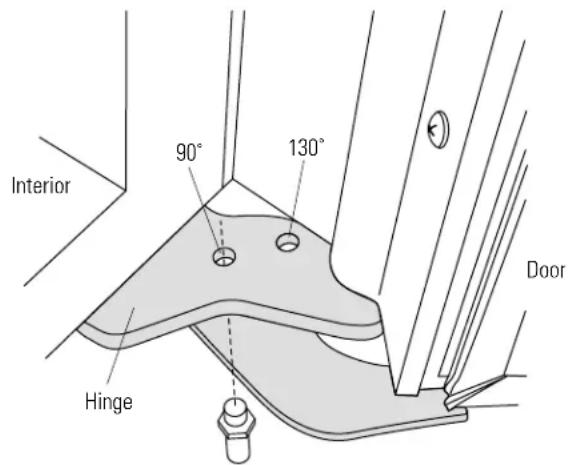
- Open the door to view the bottom hinge. Note the door stop pin locations. The pin is factory installed in the 130° position.
- Close the door. From below, use pliers to unscrew the door stop and reinstall into the 90° position.
STEP 8 INSTALL GRILLE PANEL
To insert framed or overlay panel into the grille:
- Raise the grille panel to stop position.


- Loosen screws on side trim behind frame. Remove bottom trim.
- Slide panel over the metal backer panel and into the trim.
- If necessary, tap with a wood block until panel slips under the top trim piece.
- Reassemble bottom trim. Tighten screws.
- Adjust the hinge spring to accommodate the panel weight, if necessary.
STEP 9 INSTALL FRAMED PANELS

Go to Step 9A for Overlay Panels


- Open door to 90° . Remove the 6 Phillips head screws from the door handle.
- Remove handle. Retain all screws.
- Remove 6 screws holding trim, lift off trim. Retain screws.
- Slide framed panel into the door trim.
Dispenser Models Only:
- The dispenser controls protrude beyond the face of the freezer door. To avoid damage to the dispenser, the trim at the top of the door should be removed.
- Remove the screws holding the top trim in place.
- Place the freezer panel into the bottom channel and slide into the hinge side trim.
-
Reinstall the top trim piece with screws.
-
There are two sets of holes in the handle side trim. Replace handle side trim by installing the original screws in the FRONT screw holes.
- Secure the handle to the door using the REAR screw holes.
- Follow the same procedures to install the opposite panel.
- Check to be sure handles are evenly aligned with each other at the top. To adjust, loosen handle screws and slide up or down. Tighten screws.


STEP 9A INSTALL OVERLAY PANELS


- Open door to 90° . Remove the 6 Phillips head screws from the door handle.
- Remove handle. Retain all screws.
- Remove 6 screws holding trim, lift off trim. Retain screws.
- Slide overlay panel into the door trim.
Dispenser Models Only:
- The dispenser controls protrude beyond the face of the freezer door. To avoid damage to the dispenser, the trim at the top of the door should be removed.
- Remove the screws holding the top trim in place.
- Place the assembled freezer panel into the bottom channel and slide into the hinge side trim.
-
Reinstall the top trim piece with screws.
-
There are two sets of holes in the handle side trim. Replace handle side trim by installing the original screws in the REAR screw holes.
- Secure the handle to the door using the FRONT screw holes.
- Follow the same procedures to install the opposite panel.
- Check to be sure handles are evenly aligned with each other at the top. To adjust, loosen handle screws and slide up or down. Tighten screws.


Custom handles
If you are using custom handles, the handle must be properly secured to the panel before sliding the panel into the trim.
- The cabinet manufacturer will supply the custom handle and hardware.
- Secure the door trims using both the FRONT and REAR screw holes. Use pan head screws to secure the trim. A package of 12 extra pan head screws can be found in the literature package. Discard supplied handles.
STEP 10 INSTALL DISPENSER TRIM
Skip this step is you are installing a stainless steel wrapped or a non-dispenser refrigerator.
There are two dispenser trims shipped with your refrigerator. Select the appropriate trim for your application.

Compare the dispenser trims. Note that the inside depth of the frames are different. Choose the trim with less depth for framed panels, choose the deeper one for overlay panels.
Dispenser trim fit over the custom panel depends on correct panel thickness. See pages 7 and 8 for panel construction information.

- Press and snap the dispenser trim into the dispenser recess on the refrigerator door.
If an excessive gap exists around the dispenser trim or if the panel fits loosely in the door frame, foam tape may be applied to help improve the fit. Remove the trim and panel and apply foam tape to the door around the dispenser and in the corners.
STEP 11 CONNECT WATER SUPPLY
Check to be sure that refrigerator power cord is not plugged into the wall outlet.

- Locate and bring tubing to the front of the cabinet.
- Turn the water on to flush debris from line. Run about a quart of water through tubing into a bucket, then shut-off water.
Copper Tubing:
- Slip a 1/4" nut and ferrule (provided) over both ends of the copper tubing. Insert tube into the union fitting on the unit and tighten nut to union.
• Turn on the water to check for leaks.
GE SmartConnect™ Tubing:
- Insert the molded end of the tubing into the refrigerator connection. Tighten the compression nut until it is just hand tight.
- Tighten one additional turn with a wrench. Overtightening can cause leaks!
- Turn on the water to check for leaks.
Note: Make sure excess tubing length does not interfere with tockick installation.
STEP 12 CONNECT POWER
- Check to be sure the power cord is plugged into the receptacle.

- Check to make sure power to refrigerator is on by opening refrigerator door to see if interior lights are on.
- The temperature controls are preset at 37°F for the fresh food section and 0°F for the freezer.
- Allow 24 hours to stabilize before making adjustments.
STEP 13 START ICEMAKER

- Flip the switch to I (ON). The icemaker will begin operation automatically.
- Be sure nothing interferes with the sweep of the feeler arm.
- Discard the first full bucket of ice cubes.
- To turn the icemaker off, set the switch to O (OFF).
STEP 14 INSTALL TOEKICK
- Locate the supplied toekick (shipped taped to the side of the refrigerator). Install with 2 screws provided, adjust to desired height and tighten screws.
- A custom toekick can be installed to match or complement the surrounding cabinetry. Use the supplied toekick as a template to cut the shape.

INSPECT FINAL INSTALLATION
Check door alignment
Stand back away from the refrigerator to inspect the final installation.
- Check to be sure handles are evenly aligned with each other at the top. To adjust, loosen handle screws and slide up or down. Tighten screws.
- During shipping or the addition of heavy door panels may have caused the doors to move slightly out of alignment.

- If necessary, the fresh food door may be adjusted up or down to align with the freezer door.
- Use a 5/16" wrench to adjust the hinge pin as shown.
Notes
Note: While performing installations described in this book, safety glasses or goggles should be worn.
For Monogram® local service in your area, call 1-800-444-1845.
Note: Product improvement is a continuing endeavor at General Electric. Therefore, materials, appearance and specifications are subject to change without notice.

Monogram.®
Pub. No. 49-60138-2
Dwg. No. 164D4373P001
10-03 JR
25739-1
GE Consumer Products
General Electric Company
Louisville, KY 40225
©2003 General Electric Company
- INSTALLATION INSTRUCTIONS
- BEFORE YOU BEGIN
- WARNING
- AVERTISSEMENT
- CAUTION
- PRUDENCE
- CONTENTS
- PLANNING GUIDE
- WATER AND ELECTRICAL LOCATIONS
- THE CUTOUT DEPTH MUST BE
- CUTOUT DEPTH BENEATH A SOFFIT
- ADDITIONAL SPECIFICATIONS
- PRODUCT CLEARANCES
- DESIGN GUIDE
- CUSTOMIZATION BASICS
- FRAMED OR OVERLAY PANELS, CUSTOM HANDLES AND ACCESSORY KITS
- STAINLESS STEEL WRAPPED MODELS
- TRIMMED MODELS
- STAINLESS STEEL WRAPPED REFRIGERATORS
- TRIMMED REFRIGERATORS
- FRAMED PANELS
- OPTIONAL ACCESSORY KITS
- ACCESSORY PANELS
- OVERLAY PANELS
- DOOR HANDLES
- SIDE PANELS
- FRAMED PANEL DIMENSIONS
- NON-DISPENSER MODELS
- IMPORTANT NOTE - DISPENSER MODELS
- OVERLAY PANEL DIMENSIONS
- IMPORTANT NOTE – DISPENSER MODELS
- DISPENSER MODELS: RAISED OVERLAY PANEL DESIGN
- DISPENSER TRIM FIT EXAMPLES: (NOT TO SCALE)
- FRAMED PANEL
- OVERLAY PANEL
- TOOLS REQUIRED
- HARDWARE SUPPLIED
- MATERIALS REQUIRED
- FLOORING
- GROUNDING THE REFRIGERATOR
- STEP 1 REMOVE PACKAGING
- STEP 2 INSTALL WATER LINE
- SHUT OFF THE MAIN WATER SUPPLY
- STEP 2 (CONTINUED)
- STEP 2A WATER LINE INSTALLATION WITH A REVERSE OSMOSIS SYSTEM
- STEP 3 INSTALL SIDE PANELS
- STEP 4 INSTALL ANTI-TIP BRACKETS
- WARNING: ANTI-TIP PRECAUTIONS
- ATTENTION: PRECAUTIONS CONTRE LES BASCULEMENTS
- STEP 5 LEVEL REFRIGERATOR
- STEP 7 ADJUST DOOR SWING
- STEP 8 INSTALL GRILLE PANEL
- DISPENSER MODELS ONLY
- CUSTOM HANDLES
- STEP 10 INSTALL DISPENSER TRIM
- STEP 11 CONNECT WATER SUPPLY
- COPPER TUBING
- GE SMARTCONNECT™ TUBING
- STEP 12 CONNECT POWER
- STEP 13 START ICEMAKER
- STEP 14 INSTALL TOEKICK
- INSPECT FINAL INSTALLATION
- CHECK DOOR ALIGNMENT
- MONOGRAM.®
Brand : Monogram
Model : ZISS480DMSS
Category : Refrigerator