
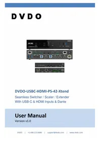
USBC-HDMI-PS-42-XTEND - Router DVDO - Free user manual and instructions
Find the device manual for free USBC-HDMI-PS-42-XTEND DVDO in PDF.


| Brand | DVDO |
| Model | USBC-HDMI-PS-42-XTEND |
| Product Type | Video Router |
| Connectivity | USB-C to HDMI |
| Video Output | HDMI 2.0 |
| Max Resolution | 3840×2160 (4K) @ 60Hz |
| Audio Support | Multi-channel digital audio pass-through |
| HDCP Support | HDCP 2.2 compliant |
| Power Source | Bus-powered via USB-C |
| Plug and Play | Yes, no drivers required |
| Compatibility | Devices with USB-C DisplayPort Alt Mode |
| Cable Length | 1.2 m integrated USB-C cable |
| Dimensions (W x H x D) | 75 × 45 × 15 mm |
| Weight | 40 g |
| Material | Aluminium alloy housing |
| Color | Space grey |
| LED Indicator | Power/signal LED |
| Operating Temperature | 0 °C to 45 °C |
| Storage Temperature | -20 °C to 60 °C |
| Warranty | 2-year limited warranty |
| Package Contents | DVDO USBC-HDMI-PS-42-XTEND, quick start guide |
| Mounting Options | Desktop or wall-mount compatible (bracket not included) |
Frequently Asked Questions - USBC-HDMI-PS-42-XTEND DVDO
User questions about USBC-HDMI-PS-42-XTEND DVDO
0 question about this device. Answer the ones you know or ask your own.
Ask a new question about this device
Download the instructions for your Router in PDF format for free! Find your manual USBC-HDMI-PS-42-XTEND - DVDO and take your electronic device back in hand. On this page are published all the documents necessary for the use of your device. USBC-HDMI-PS-42-XTEND by DVDO.
USER MANUAL USBC-HDMI-PS-42-XTEND DVDO
For optimum performance and safety, please read these instructions carefully before connecting operating or adjusting this product. Please keep this manual for future reference.
Surge protection device recommended
This product contains sensitive electrical components that may be damaged by electrical spikes, surges, electric shock, lighting strikes, etc. Use of surge protection systems is highly recommended in order to protect and extend the life of your equipment.
Caution
The product requires the use of UTP connectors. Please connect in direct interconnection method and do not cross connect.

Direct Interconnection Method
Table of Contents
- Introduction......1
- Features....1
- Package Contents......2
- Specifications....2
- Operation Controls and Functions....4
5.1 Switch Panel....4
5.2 HDBaseT Receiver Panel 7 - IR Remote 8
- IR Cable Pin Assignment....9
- Multiview....9
- Keyboard & Mouse Hotkey Function....10
- Web GUI Operation Guide ....11
- RS-232 Control Command 23
- Connection Diagram....40
1. Introduction
DVDO-USBC-HDMI-PS-42-Xtend is a 4x2 seamless presentation switcher that supports video resolutions up to 4K@60Hz 4:4:4 8bit deep color and is HDCP 2.3 compliant. It features a multiview function where multiple sources can be displayed on a single screen. It has two HDMI and one HDBaseT 3.0 outputs. The HDBaseT output is mirrored with HDMI OUT 2 and extends uncompressed 4K60Hz 4:4:4 signals up to 132ft/40m or 4K30Hz/1080P60Hz signals up to 230ft/70m via a single Cat6A cable.
DVDO-USBC-HDMI-PS-42-Xtend features two USB-C and two HDMI inputs. Each USB-C input supports DisplayPort alternate mode A/V up to 4K@60Hz 4:4:4 8bit deep color, USB 3.2 Gen 1 5Gbps data and up to 60 watts power charging to USB-C source device. It also features 1Gbps Ethernet over USB-C functionality to allow USB-C source device to access internet seamlessly. Local USB 3.2 KVM switching and extending USB 2.0 high speed over HDBaseT 3.0 can be allowed to connect external USB 2.0 devices or cameras from RX remote side for video conference.
DVDO-USBC-HDMI-PS-42-Xtend also supports audio embedded and de-embedded and a built-in DSP for audio mixing, matrixing, independent EQ/volume/delay adjustment. It also supports Dante 2x2 audio input and output interface, and it can be seamlessly connected to any existing Dante enabled audio processing system.
DVDO-USBC-HDMI-PS-42-Xtend can be controlled via front panel buttons, IR remote control, API commands using RS-232 or TCP/IP with an intuitive web GUI.
2. Features
☆ Video resolution up to 4K@60Hz 4:4:4, as specified in HDMI 2.0b
☆ HDCP 2.3, DP 1.4 and HDBase 3.0 compliant
☆ USB 3.2 Gen 1 up to 5Gbps
☆ 4x2 seamless switching (single screen) and fast switching (multiview) function
☆ Manual switching or auto switching mode
☆ Multiple multiview display modes: Auto/Single/PIP/PBP/Triple/Quad/Custom
Input: 2x USB-C, 2x HDMI, 1x Analog audio, 1x Dante 2ch
☆ Output: 1x HDMI, 1x HDMI + HDBaseT mirrored, 1x Analog audio, 1x Dante 2ch
☆ USB-C supports DisplayPort Alternate mode for A/V, USB 3.2, 1G LAN and 60W charging
☆ Local USB 3.2 switching and extending USB 2.0 over HDBaseT 3.0
☆ Local USB KVM hotkeys and mouse switching
☆ Uncompressed 4K60 4:4:4 over HDBaseT 3.0 up to 132ft/40m via single CAT6A cable
☆ Uncompressed 1080P&4K30 over HDBaseT 3.0 up to 230ft/70m via single CAT6A cable
☆ Audio embedded and de-embedded
☆ Audio DSP for gain, equalizer, volume and delay
☆ Dante 2x2 audio input and output
☆ CEC/RS-232 control external devices ON/OFF
☆ Advanced EDID management
☆ Support standard PoE power supply from TX to RX (TX_PSE, RX_PD)
★ Flexible control via front panel buttons, IR remote, RS-232, TCP/IP or Web GUI
3. Package Contents
① 1x 4x2 Seamless Presentation Switch
② 1x HDBaseT Receiver
③ 1x IR Blaster Cable (1.5 meters)
④ 1x IR Wideband Receiver Cable (1.5 meters)
⑤ 3x 3pin-3.5mm Phoenix Connector (male)
⑥ 3x 5pin-3.5mm Phoenix Connector (male)
⑦ 4x Mounting Ear
⑧ 8x Machine Screw
⑨ 1x 24V/8A Desktop Power Supply & 1 x AC Power Cord (1.5 meters)
⑩ 1x IR Remote
11 1x User Manual
4. Specifications
| Technical | |
| HDMI Compliance | HDMI 2.0b |
| HDCP Compliance | HDCP 2.3 |
| DP Version | DP 1.4 |
| Video Bandwidth | 18Gbps |
| USB Bandwidth | USB 3.2 Gen 1 up to 5Gbps |
| Network Bandwidth (LAN and USB-C Connection) | 1Gbps |
| Video Resolution | Up to 4K@60Hz 4:4:4 |
| IR Level | 12Vp-p |
| IR Frequency | Wideband 20K-60KHz |
| Color Depth | 8/10/12-bit |
| Color Space | RGB, YCbCr_4:4:4, YCbCr_4:2:2, YCbCr_4:2:0 |
| Audio Formats | USB-C/HDMI/HDBT: Digital audio, 32-192kHz/24bit, LPCM 2CHLINE IN: Analog audio, Balanced/unbalanced 2CH, Max input level 2VrmsLINE OUT: Analog audio, Balanced 2CH (Max output level 2Vrms)/unbalanced 2CH (Max output level 1Vrms)DANTE: Digital audio 2x2 in/out, LPCM 2CH 44.1K-96KHz 16/24Bit] |
| Transmission Distance | HDBT: 230ft/70m (1080P&4K30), 131ft/40m (4K60)HDMI: 9.8ft/3mUSB-C: 9.8ft/3m |
| ESD Protection | IEC 61000-4-2: ±8kV (Air-gap discharge), ±4kV (Contact discharge) |
| TX Analog Audio | |
| Input Impedance | 10K Ohms |
| Output Impedance | 330 Ohms |
| Line Input Level (Maximum) | 8.2dBu (2Vrms) @ balanced or unbalanced audio |
| Line Output Level (Maximum) | 8.2dBu (2Vrms) @ balanced audio2.2dBu (1Vrms) @ unbalanced audio |
| Frequency Response | (+0.5 dB, -1 dB) 20 Hz to 20 kHz |
| Audio Output Sync Delay | < 1ms |
| Audio S/N Ratio | 93dB @ 2Vrms, 1kHz A-weighted |
| Audio THD+N | <0.1% @ 0dBV, 1kHz |
| RX Analog Audio | |
| Output Impedance | 330 Ohms |
| Line Output Level (Maximum) | 8.2dBu (2Vrms) @ balanced audio2.2dBu (1Vrms) @ unbalanced audio |
| Frequency Response | (+0.5 dB, -1 dB) 20 Hz to 20 kHz |
| Audio Output Sync Delay | 0 to 50ms |
| Audio S/N Ratio | 93dB @ 2Vrms, 1kHz A-weighted |
| Audio THD+N | <0.1% @ 0dBV, 1kHz |
| Dante Audio | |
| Audio Formats | LPCM 2CH |
| Sample Rate | 44.1/48/88.2/96KHz at 24 bits |
| Audio Delay | 2/3/4/5/10ms |
| Network Bandwidth | 100Mbps |
| Connection | |
| Transmitter | Input: 2x HDMI IN [HDMI Type A, 19-pin female]2x USB-C IN [Type C, 24-pin female]1x LINE IN [5pin-3.5mm phoenix connector]1x DANTE IN [RJ45]Output: 2x HDMI OUT [HDMI Type A, 19-pin female]1x HDBT OUT [RJ45, 48V POE/PSE]1x LINE OUT [5pin-3.5mm phoenix connector]Control: 1x RS-232 [3pin-3.5mm phoenix connector]1x RS-232 CTL [3pin-3.5mm phoenix connector]1x LAN [RJ45]2x USB 3.2 HOST [USB Type B, 9-pin female]3x USB 3.2 DEVICES [USB Type A, 9-pin female]2x USB 1.1 KVM [Type A, 4-pin female]1x USB-C DEVICE [Type C, 24-pin female]1x IR IN [3.5mm audio jack, 12V level]1x IR OUT [3.5mm audio jack, 12V level] |
| Receiver | Input: 1x HDMI IN [Type A, 19-pin female]1x HDBaseT IN [RJ45, 48V POE/PD]Output: 1x HDMI OUT [Type A, 19-pin female]1x LINE OUT [5pin-3.5mm phoenix connector]Control: 1x RS-232 [3pin-3.5mm phoenix connector]1x USB HOST [Type B, 4-pin female]2x USB DEVICES [Type A, 4-pin female]1x SERVICE [Micro USB, 5-pin female]1x IR IN [3.5mm audio jack, 12V level]1x IR OUT [3.5mm audio jack, 12V level] |
| Mechanical | |
| Housing | Front panel: Aluminum; Rear case: Metal Enclosure |
| Color | Black |
| Dimensions | Transmitter: 220mm [W] × 220mm [D] × 44.5mm [H]Receiver: 140mm [W] × 105mm [D] × 21.5mm [H] |
| Weight | Transmitter: 1.78Kg; Receiver: 424g |
| Power Supply | Input: AC100 - 240V 50/60HzOutput: DC 24V/8A (US/EU standard, CE/FCC/UL certified) |
| Power Consumption | 170W (Max) |
| Operating Temperature | 0°C ~ 40°C / 32°F ~ 104°F |
| Storage Temperature | -40°C ~ 60°C / -40°F ~ 140°F |
| Operating Humidity | 20%~80% (relative humidity, non-condensing) |
| Storage Humidity | 10%~90% (relative humidity, non-condensing) |
5. Operation Controls and Functions
5.1 Switch Panel
Front Panel

| No. | Name | Function Description |
| 1 | POWER button | Press and hold this button for 3 seconds, the unit will enter the standby mode and the button light will be red. In standby mode, short press this button, the unit will be turned on and the button light will be blue. |
| 2 | IR Window | IR signal receiving window, receiving the IR remote signal to control certain functions of the machine. |
| 3 | OUT 1 button | Press this button to select the input channel for HDMI OUT 1.When the OUT 1 port is connected to a display device, the button light is on; otherwise the button light is off. |
| 4 | USB-C 1/USB-C 2/HDMI 3/HDMI 4,AUTO LEDs | USB-C 1/USB-C 2/HDMI 3/HDMI 4: Indicates the selected status of each input channel. Steady green indicates that the corresponding input channel is selected, and off indicates that the input channel is not selected.AUTO: Indicates that the unit is in the auto switching/automatic layout state (setting via Web GUI), and the last connected signal source is the input source of HDMI output. |
| 5 | OUT 2 button | Press this button to select the input channel for HDMI OUT 2.When the OUT 2 port is connected to a display device, the button light is on; otherwise the button light is off. |
| 6 | USB 1.1 KVM ports | USB 1.1 device ports, connected to keyboard and mouse,supporting hotkey function and 5V/500mA output. |
| 7 | USB DEVICES 1/2 ports | USB extension ports, supporting USB 3.2 Gen 1 and 5V/900mA output, connected to USB 3.0 flash disk, camera, printer etc. |
Rear Panel

| No. | Name | Function Description |
| 1 | DANTE port | Dante Network port, connected to the Switch with other Dante receivers. This port supports receiving and transmitting signals. |
| 2 | LINE IN port | Analog audio input port, supporting balanced/unbalanced audio input, with a maximum support of 2Vrms.Balanced connection method: L+, L-, R+, R-Unbalanced connection method: L+, , R+ |
| 3 | LINE OUT port | Analog audio output port, supporting balanced audio output (with a maximum support of 2Vrms) and unbalanced audio output (with a maximum support of 1Vrms).Balanced connection method: L+, L-, R+, R-Unbalanced connection method: L+, , R+ |
| 4 | IR IN port | Connect the IR receiver cable, used for IR signal pass-through or controlling this product via the IR remote. |
| 5 | IR OUT port | Connect the IR blaster cable, the IR signal is from the IR IN port of the HDBaseT Receiver. |
| 6 | RS-232 port | RS-232 serial port, with two functions:(1) RS-232 signal pass-through or control external devices;(2) Update valens firmware and hotkey function firmware (switch the serial port via API commands) |
| 7 | RS-232 CTL port | RS-232 serial port, used for API commands control and MCU update. |
| 8 | RESET button | Press and hold this button for 5 seconds, all LEDs on the front panel will flash at 1Hz. When LEDs stop flashing, it indicates that the unit has been restored to factory default settings. |
| 9 | LAN port | 1G Ethernet port, TCP/IP and Web GUI, connected to a router or network Switch for control or Ethernet access. |
| 10 | DC 24V port | Power port, connected to the DC 24V power adapter. |
| 11 | USB DEVICES 3/4 ports | USB expansion ports, supporting USB 3.2 Gen 1 and 5V/900mA output, connected to USB 3.0 flash disk, camera, printer etc. |
| 12 | USB-C 1/2 ports | USB-C ports, with four functions:(1) USB-C signal input ports, connected to USB-C signal source devices.(2) USB Host ports, supporting USB 3.2 Gen 1 5Gbps.(3) Providing 60W charging for the external device.(4) Supporting USB-C access network feature. |
| 13 | HOST 3/4 ports | USB Host ports, supporting USB 3.2 Gen 1 5Gbps. |
| 14 | IN 3/4 ports | HDMI signal input ports, connected to HDMI source device such as DVD or Blu-ray player with HDMI cable. |
| 15 | OUT 1/2 ports | HDMI signal output ports, connected to HDMI display device such as TV or monitor with HDMI cable. |
| 16 | HDBT 2 port | HDBaseT output port, connected to the HDBaseT IN port of the receiver with a CAT6A (F/FTP) cable. |
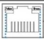
| 17 | Data Signal Indicator (Yellow) | Light on: There is video signal input with HDCP.Light flashing: There is video signal input without HDCP.Light off: There is no video signal input. |
| 18 | Link Signal Indicator (Green) | Light on: Transmitter and Receiver are connected and linked.Light flashing: The link between the Transmitter and Receiver is abnormal.Light off: Transmitter and Receiver are not linked. |
5.2 HDBaseT Receiver Panel

| No. | Name | Function Description |
| 1 | Power LED | When the receiver is powered on, the red power LED will be on. |
| 2 | LINK LED | ·Light on: Transmitter and Receiver are in good connection status.·Light flashing: Transmitter and Receiver are in poor connection status.·Light off: Transmitter and Receiver are not connected. |
| 3 | VIDEO LED | ·Light on: There is video signal input with HDCP.·Light flashing: There is video signal input without HDCP.·Light off: There is no video signal input. |
| 4 | HDBT LED | When the HDBaseT IN port is selected as the signal input channel, the green HDBT LED will be on. |
| 5 | HDMI LED | When the HDMI IN port is selected as the signal input channel, the green HDMI LED will be on. |
| 6 | SELECT button | Press this button to select signal input channel. |
| 7 | IR IN port | Connect the IR receiver cable, the IR signal will be sent to the IR OUT port of the transmitter. |
| 8 | IR OUT port | Connect the IR blaster cable, the IR signal is from the IR IN port of the transmitter. |
| 9 | DEVICES ports | USB extension ports, supporting USB 2.0 and 5V/500mA output, connected to whiteboard, mouse, keyboard or other USB devices. |
| 10 | SERVICE port | Firmware update port. |
| 11 | HDBaseT IN port | HDBaseT input port, connected to the HDBT 2 port of the transmitter with a CAT6A (F/FTP) cable. |
| 12 | Data Signal Indicator (Yellow) | ·Light on: There is video signal input with HDCP.·Light flashing: There is video signal input without HDCP.·Light off: There is no video signal input. |


| No. | Name | Function Description |
| 13 | Link Signal Indicator (Green) | ·Light on: Transmitter and Receiver are connected and linked.·Light flashing: The link between the Transmitter and Receiver is abnormal.·Light off: Transmitter and Receiver are not linked. |
| 14 | HDMI IN port | HDMI signal input port, connected to HDMI source device such as DVD or Blu-ray player with HDMI cable. |
| 15 | HOST port | USB Host port, supporting USB 2.0. |
| 16 | HDMI OUT port | HDMI signal output port, connected to HDMI display device such as TV or monitor with HDMI cable. |
| 17 | LINE OUT port | Analog audio output port, supporting balanced audio output (with a maximum support of 2Vrms) and unbalanced audio output (with a maximum support of 1Vrms).Balanced connection method: L+, L-, ±, R+, R-Unbalanced connection method: L+, ±, R+ |
| 18 | RS-232 port | RS-232 serial port, used for RS-232 signal pass-through or controlling external device. |
| 19 | DC 24V port | Power input port, connected to the DC 24V power adapter.Note: The receiver also can be powered by PoE (through the HDBaseT IN port). |
6. IR Remote

① Power button: Press this button to power on the switch or set it to standby mode.
② OUT 1/2 buttons:
USB-C 1/USB-C 2/HDMI 3/HDMI 4: Press these buttons to select input source for OUT 1/2 in single screen display mode, and the corresponding input LED on the front panel will light in green.
: Multiview display mode switching button. Short press this button to circularly select: Single - PIP - PBP-Triple - Quad.
◀▶: Press these buttons to circularly select the previous or next input source for OUT 1/2 in single screen display mode.
AUTO: Press this button to enable/disable the auto switching function.
RES.: Press this button to cycle through the output resolution.
MUTE: Press this button to mute/unmute the audio of OUT 1/2.
VOL-, VOL+: Press these buttons to increase/decrease the audio output volume of OUT 1/2.
③ Universal buttons:
RX HDBT: Press this button to select the HDBaseT IN port as the signal source input channel of the receiver.
RX HDMI: Press this button to select the HDMI IN port as the signal source input channel of the receiver.
PRESET: Press this button to cycle through the preset application scenes.
7. IR Cable Pin Assignment
The pin assignment of the IR Receiver cable and IR Blaster cable is as below:

Note: When the angle between the IR receiver and the remote control is ± 45° , the transmission distance is 0-5 meters; when the angle between the IR receiver and the remote control is ± 90° , the transmission distance is 0-8 meters.
8. Multiview
The presentation switch supports multiple multiview display modes:
Auto: When the Auto mode is selected, the multiview display modes set through Web GUI will be recalled automatically.
Single: Single screen display mode.
PBP: Dual screen display modes, including Dual-LR and Dual-TB.
PIP: PIP screen display modes, including PIP-LT, PIP-LB, PIP-RT and PIP-RB
Triple: Triple screen display modes, including Triple-L, Triple-R, Triple-T and Triple-B
Quad: Quad screen display modes, including Quad-L, Quad-R, Quad-T, Quad-B and Quad-S
Custom: Five customized multiview dispay modes are supported.
Multiview window distributions are as following:

You can set/select multiview display modes via Web GUI. For details, please refer to the Video and System interface operation of "10. Web GUI Operation Guide".
In addition, you can select multiview display modes via IR remote control or RS-232 commands.
9. Keyboard & Mouse Hotkey Function
The presentation switch supports hotkey function, you can use keyboard and mouse hot keys to operate and control the switch.
(1) Keyboard hotkeys are as following:

Note: Do not use the keypad on the right of the keyboard.

(2) Mouse hotkeys are as following:
Double-Click Middle-Right (Double-click the mouse scroll wheel, and then click the right button): Switch output 1 to next input
Double-Click Middle-Left (Double-click the mouse scroll wheel, and then click the left button): Switch output 2 to next input
10. Web GUI Operation Guide
The presentation switch can be controlled by Web GUI. The operation method is shown as below:
Step 1: Get the current IP Address.
The default IP address is 192.168.0.100 (when the system is not connected to a router). You can get the current switch IP address via RS-232 command control. Send the ASCII command "get ip addr" through a Serial Command tool, then you'll get the current IP address (The IP address is variable, depending on what the specific machine returns).
For the details of RS-232 control, please refer to "9. RS-232 Control Command".
Step 2: Connect the LAN port of the presentation switch to a PC with an UTP cable (as shown in the following figure), and set the IP address of the PC to be in the same network segment with the presentation switch.

Step 3: Input the current IP address of switch into your browser on the PC to enter Web GUI interface.

After entering the Web GUI page, there will be a Login interface, as shown below:

The default usernames and passwords are as below:
| Username | Password |
| Admin | 1234 |
| User | 1234 |
Select the username "User" and input the password "1234", then click the "Login" button to enter the User page.
■ User Page

You can do the following operations on the User page:
① Preset: Recall the preset application scenes.
② Video: Set the window display mode for HDMI Out 1 and HDMI/HDBT Out 2, select input source for each screen, freeze the screen, mute the audio, or turn off the output stream.
③ Master Out: Set the audio volume or mute/unmute the audio for Master Out. You can respectively turn on/off the HDMI Out 1, HDMI/HDBT Out 2, Line Out or Dante Out.
In the Login interface, select the username "Admin" and input the password "1234", then click the "Login" button to enter the Information page of the Admin interface.
■ Information Page

The Information page provides basic information about the model name, software version, Web version, Dante version, FPGA version, RX version, IP information, the current machine temperature, fan status and online time.
Besides, you can do the following operations in the upper right corner of each page.
① Display and set the audio volume of Master Out. Click the volume icons to increase/decrease the audio volume of Master Out, or click the mute icon to mute/unmute the audio of Master Out. When muted, the mute icon displays red.
② Display the current username (User or Admin).
③ Click the power icon to power on the switch or set it in standby mode.
④ Click the logout icon to logout and return to the login interface.
■ Preset Page

You can set up to 8 preset scenes on the Preset page.
① Preset Name: You can name the preset scene (16 characters max).
② Preset Save: Click the Save button to save the scene.
③ Preset Clear: Click the Clear button to clear the saved scene.
④ Preset Recall: Click the Recall button to recall the saved scene.
■ Input Page

You can do the following operations on the Input page:
① Input: Input channel of the device.
② Name: The input channel's name. You can modify it by entering the corresponding name (16 characters max) in the input box.
③ Cable: It indicates whether the channel is connected/disconnected to the signal source.
④ Signal: It indicates the signal status.
⑤ EDID: Click the drop-down list to set EDID for each input port. The EDID list is as below.
| No. | EDID Mode | No. | EDID Mode |
| 1 | Auto | 10 | 1680x1050, Stereo Audio 2.0 |
| 2 | Copy HDMI Out 1 | 11 | 1600x1200, Stereo Audio 2.0 |
| 3 | Copy HDMI Out 2 | 12 | 1440x900, Stereo Audio 2.0 |
| 4 | Copy HDBT Out 2 | 13 | 1360x768, Stereo Audio 2.0 |
| 5 | 4K2K60_444, Stereo Audio 2.0 | 14 | 1280x1024, Stereo Audio 2.0 |
| 6 | 4K2K30_444, Stereo Audio 2.0 | 15 | 1024x768, Stereo Audio 2.0 |
| 7 | 1080P, Stereo Audio 2.0 | 16 | User Defined 1 |
| 8 | 720P, Stereo Audio 2.0 | 17 | User Defined 2 |
| 9 | 1920x1200, Stereo Audio 2.0 |
Notes:
(1) When the EDID is set to "Auto", it depends on the EDID of TV. The optimal resolution will be selected based on the EDID of the back-end TV with the lowest resolution.
(2) Please import the user-defined EDID before selecting User Defined 1/2 as the EDID.
⑥ hdcp: Click the drop-down menu to set the HDCP for each input port.
⑦ Export EDID to your computer: Click the drop-down menu to select the input/output/user-defined EDID, then click "Download".

⑧ Import user-defined EDID: Click "Load EDID" to load User Defined 1/2 EDID, then click "Save EDID".

■ Output Page

You can do the following operations on the Output page:
① Output: Output channel of the device.
② Name: The current output channel's name. You can modify it by entering the corresponding name (16 characters max) in the input box.
③ Cable: It indicates the connection status of the output channel.
④ Signal: It indicates the signal status.
⑤ Scaling: Click the drop-down list to select the output resolution. The output resolution list is as following.
| No. | Output Resolution | No. | Output Resolution |
| 1 | Auto | 9 | 1920x1080i60 |
| 2 | 3840x2160p60 | 10 | 1920x1080i50 |
| 3 | 3840x2160p50 | 11 | 1280x720p60 |
| 4 | 4096x2160p60 | 12 | 1280x720p50 |
| 5 | 4096x2160p50 | 13 | 1360x768p60 |
| 6 | 3840x2160p30 | 14 | 1280x800p60 |
| 7 | 1920x1080p60 | 15 | 1920x1200p60RB |
| 8 | 1920x1080p50 | 16 | 1024x768p60 |
Notes:
(1) When the output resolution is set to "Auto", the presentation switch will output the matching resolution based on the EDID of the back-end TV.
(2) The output resolution can not be set separately in the multiview mode.
⑥ HDCP: Click the drop-down list to set the HDCP (Auto/HDCP 1.4/HDCP 2.2/Reserved).
⑦ On/Off: Click the drop-down list to turn on/off the output display.


■ Video Page

Window layout
Click the drop-down list to select the display mode (Auto/Single/PIP/PBP/Triple/Quad/Custom) for each output port, as shown in the following left figure. Then click the drop-down list of the input source to select the signal source for each window, as shown in the following right figure.

If you select the custom window layout (Custom1/2/3/4/5), you can freely set the window size, position and input source, as shown in the following figure.

Moreover, after selecting a window in Custom1/2/3/4/5, you can perform additional settings.

1) Window Select: Click the 1/2/3/4 button to select the window, or direct click the window in the window layout.
2) Active: This switch is used to hide the window. Select the window, and turn off the Active switch, then the window will be hidden; Select the hidden window, and turn on the Active switch, then the window will appear again.
3) Window Priority: Click the corresponding button to set the window display priority.
4) Window Aspect: Click the corresponding button to set the window display aspect ratio.
Maintain: Adaptively adjust the window display aspect ratio based on the ratio provided by the signal source.
Custom: Adjust the window display aspect ratio according to user customization.
16:10/16:9/4:3: Fixed window display aspect ratio.
5) Coordinate X/ Coordinate Y: Click the drop-down list to set the window coordinate.
6) Horizontal Width/Vertical Height: Click the drop-down list to set the ratio of window width to height.
7) Window Border: Click the drop-down list to set the color of the window border (Off/Black/Red/Green/Blue/Yellow/Magenta/Cyan/White/Gray).
8) Reset: Click the Reset button to clear the settings of the custom window.
9) Save Layout As: Click the drop-down list to select the layout mode according to the number of windows, then click "Save" to save the current custom window layout as dual/triple/quad user-defined screen, which can be selected and recalled in the Auto Switch interface on the System page.

Freeze the screen
(1) When both outputs are in the single screen display mode, you can click the Freeze button to separately freeze the display screen of OUT 1 or OUT 2.
(2) When both outputs are in the multiview display mode, clicking the Freeze button will freeze both the screens of OUT 1 and OUT 2.
(3) When one output is in the single screen display mode, and the another output is in the multiview display mode, the freeze function is only available for the multiview display mode.
AV MUTE
Clicking the AV MUTE button, the corresponding output device will display black screen and mute the audio.
Turn off the output stream
Click the Turn Off button to turn off the output port, and there is no signal output.

Audio Matrix
The presentation switch features four input ports (USB-C 1, USB-C 2, HDMI 3 and HDMI 4), meanwhile, the audio output from HDMI OUT 1/2 can be used as the audio input source. Therefore, there are five audio signal sources for Main In 1 and Main In 2, as shown in the figure below.


Click the drop-down list to select the audio source for Main In 1/2, and select one or multiple audio sources for each output port by clicking the corresponding button of Main In 1/Main In 2/Line in/Dante in, then an audio matrix forms.
In the audio matrix, multiple audio inputs can be selected for mixing output, and the mixing ratio can be adjusted with a Gain volume bar. When a single audio output is selected, the audio gain can be adjusted with a Gain volume bar, too.

Follow Output
Click the corresponding button to set the Line Out/Dante Out follow the output of HDMI Out 1 or HDMI/HDBT Out 2.

Input Setting
You can respectively set the audio volume or mute/unmute the audio for Main In 1/Main In 2/Line In/Dante In.

Output Setting
① Master Out: System volume adjustment. Select the synchronization button to synchronize the volume of each audio output according to the Master Out volume bar. When adjusting the volume bar of the audio output separately, the synchronization button will automatically turn off.
② HDMI Out 1/HDMI/HDBT Out 2/Line Out/Dante Out: Click the drop-down list of Mix to select the audio output channel for HDMI Out 1/HDMI/HDBT Out 2/Line Out/Dante Out. You can set the delay, increase/decrease the audio or mute/unmute the audio.

GEQ Setting
① Output: Click the drop-down list to select the output channel.
② Equalizer: Click the drop-down list to set the equalizer status of different output audio.
Flat: Set all EQ to 0db.
Custom1: Set EQ for custom 1.
Custom2: Set EQ for custom 2.
Custom3: Set EQ for custom 3.
Custom4: Set EQ for custom 4.

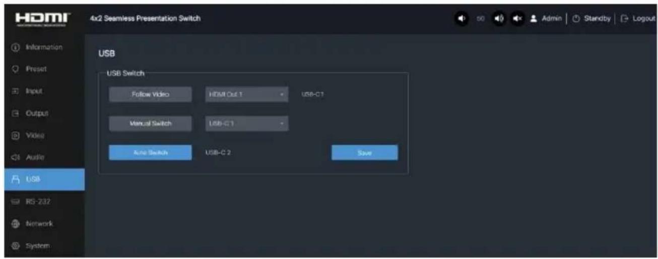
■ USB Page
USB Switch
① Follow Video: Click this button to set the USB transmission follow the video. Click the drop-down list to set it follow the video output of HDMI Out 1 or HDMI/HDBT Out 2.
② Manual Switch: Click this button to enter the manual switching mode, then click the drop-down list to select USB-C 1/USB-C 2/Host 3/Host 4 as the upstream port.
③ Auto Switch: Click this button to enter the auto switching mode. The system will detect and switch to the last connected port as the upstream port automatically. After setting up, click "Save" to take effect.
■ RS-232 Page

RS-232 Settings
① Local RS-232: You can set the Baud Rate, Data Bit, Parity and Stop Bit for the RS-232 port of the transmitter.
② Remote RS-232: You can set the Baud Rate, Data Bit, Parity and Stop Bit for the RS-232 port of the receiver.
After setting up, please click "Save" to take effect.

RS-232 Commands (Display Auto Power)
① Local/Remote RS-232 Commands: You can turn on/off the local/remote RS-232 commands and HEX.
② Display On/Off Command: You can input the display on/off command of the external device.
③ Delay 1: You can set the delay time for the next action (such as send the Display Input Select command).
④ Display Input Select: You can input the command of switching the input channel for the display device.
⑤ Delay 2: You can set the delay time for the next action after sending the Display Input Select command.
After setting up, please click "Save" to take effect.
■ Network Page

Network Configuration
You can set the IP Mode (Static/DHCP). If the mode is set to "Static", you can manually set the IP Address, Subnet Mask, Gateway, Tenet Port and Domain Name as required, then click "Save" to take effect. If the mode is set to "DHCP", the system will search and fill the IP Address with the one assigned by the router automatically. You can't modify it now.
Note: The Domain Name "psb42kvm.local" can be used to login the Web GUI.
■ System Page

Auto Switch
① Trigger Mode: Click the drop-down list to select Signal/Source 5V as the trigger mode for auto switching.
② Output 1/2 Fallback Input: Click the drop-down list to select Next Input/USB-C 1/USB-C 2/HDMI 3/HDMI 4/RX HDMI as the signal source of Fallback input. With the auto switching function enabled, when connecting signal sources, the output signal will switch to the last connected signal source automatically. When the current signal source is disconnected, if the Fallback input is set to "Next Input", the output signal will switch according to the order of input ports. For example, when disconnecting Input 1, the output signal will switch to Input 2. If the Fallback input is set to a fixed input, the output signal will switch to the selected input.
Note: The auto switching function is available only in single screen display mode.
③ Output 1/2 Layout: Set the display mode of the output 1/2 port, which can be configured as single screen or multiview. In multiview mode, dual screen/triple screen/quad screen can be displayed according to the number of connected sources.
④ Output 1/2 Dual/Triple/Quad Windows: Dual/Triple/Quad screen window setting, allowing users to freely choose the layout of dual/triple/quad screen display and customize the layout. User customized layout can be saved as a dual/triple/quad screen window in the layout customization (Custom 1/2/3/4/5) of the Video page, and then selected and called in the Output 1/2 Dual/Triple/Quad Windows column of the System page.
Display Control
① CEC Command: Click the corresponding button to power on/off the display device.
② Display Auto Power: You can turn on/off the Display Auto Power. When it is set to ON, you can control the display device power on/off by sending RS-232 command or CEC Power On/Off command.
③ Auto Power off Timer: Click the drop-down list to select the delay time for sending the command to turn off the display device when the transmitter is in standby mode or there is no signal input.
④ Control Type: Set the display device control type (CEC/RS-232/CEC and RS-232).

System Utilities
① Front Panel Buttons: Click "ON/OFF" to lock/unlock panel buttons. "ON" indicates that panel buttons are available; "OFF" indicates panel buttons are unavailable.
② Beep: Click "ON/OFF" to turn on/off the beep.
③ Fan Speed: Click the drop-down list to set the fan speed (Auto/25%/50%/75%/100%).
④ Reboot: Click "Reboot" to reboot the switch.
⑤ Restore Factory Settings: Click this button to restore the switch to factory settings.
⑥ Restore Factory (Including Network) : Click this button to restore the switch to factory settings (including the network configuration).
⑦ Export Settings: Click this button to export system configuration files.
⑧ Import Settings: Click this button to import system configuration files.
Firmware Update: You can update the software of MCU, Web, Scaler or receiver. Click "Choose File" to select the update file, then click "Update" to start update. When the progress bar reaches 100%, the update is complete.
Account Passwords: You can modify the login password (16 characters max) for User and Admin.
After setting up, click "Save" to take effect.
11. RS-232 Control Command
The product also supports RS-232 command control. Connect the RS-232 CTL port of the product to a PC with a 3-pin phoenix connector cable and an RS-232 to USB cable. The connection method is as follows.

Then open a Serial Command tool on PC to send ASCII commands to control the product. The ASCII command list about the product is shown as below.
| ASCII Command | ||||
| Serial port protocol: Baud rate: 115200 (default), Data bits: 8bit, Stop bits:1, Parity bit: noneTCP/IP protocol port: 8000 | ||||
| x - Parameter 1. y - Parameter 2. The end mark of command is “”. | ||||
| Command Code | Function Description | Example | Feedback | Default Setting |
| System Setting | ||||
| ? | Get the list of all commands | ? | ||
| help | Get the list of all commands | help | ||
| get model | Get device model | get model | PS42KVM | |
| status | Get device current status | status | Please refer to the note at the end of the list. | |
| get version | Get Firmware version | get version | MCU 1.1.0 Web 1.1.0FPGA 1.1.0 RX 1.18.02 | |
| power on | Power on the device | power on | Power on System Initializing... Initialization Finished!MCU 1.1.0 Web 1.1.0FPGA 1.1.0 RX 1.18.02 | |
| power off | Power off the device | power off | Power off | |
| get power | Get current power state | get power | power on /power off | |
| reboot | Reboot the device | reboot | Reboot... System Initializing... Initialization Finished!MCU 1.1.0 Web 1.1.0FPGA 1.1.0 RX 1.18.02 | |
| reset | Reset system settings to default (Should type "Yes" to confirm, "No" to discard) | reset | Sure to Reset System Settings To Default? Type "Yes" after next prompt to confirm... | |
| reset all | Reset system and network settings to default (Should type "Yes" to confirm, "No" to discard) | reset all | Sure to Reset System and Network Settings To Default? Type "Yes" after next prompt to confirm... | |
| s front button x | Set front button locked on/off (x=0~1)x=0: Unlocked x=1: Locked | s front button 0 | Set front button unlocked | 0 |
| get front button | Get front button locked on/off status | get front button | Unlocked | |
| set beep x | Set buzzer on/off (x=0~1)x=0: Off x=1: On | set beep 0 | Set beep off | 0 |
| get beep | Get buzzer on/off status | get beep | Off | |
| set ir x | Set IR on/off (x=0~1)x=0: Off x=1: On | set ir 1 | Set IR on | 1 |
| get ir | Get IR on/off status | get ir | On | |
| set UsbcAccess Network x | Set USB-C (x=0~3) access network featurex=0: All USB-C Inputsx=1: USB-C 1x=2: USB-C 2x=3: None | set UsbcAccess Network 0 | Set all USB-C inputs access network | 1 |
| get UsbcAccess Network | Get USB-C access network feature status | get UsbcAccess Network | All USB-C inputs | |
| set fan speed x | Set fan speed (x=0~4)x=0: Auto x=1: 25% x=2: 50%x=3: 75% x=4: 100% | set fan speed 0 | Set fan speed auto | 0 |
| get fan speed | Get fan speed | get fan speed | Auto | |
| get temp | Get device internal temperature | get temp | 65C | |
| Command Code | Function Description | Example | Feedback | Default Setting |
| get uptime | Get device running time(Day:Hour:Min:Sec) | get uptime | 000:00:13:04 | |
| Input Setting | ||||
| set input x edid y | Set input (x=0~4) EDID (y=1~17)x=0: All Inputsx=1: USB-C 1x=2: USB-C 2x=3: HDMI 3x=4: HDMI 4y=1: Auto (HDBT or HDMI or HDBT+HDMI)y=2: Copy HDMI Out 1y=3: Copy HDMI Out 2y=4: Copy HDBT Out 2y=5: 4K2K60_444, Stereo Audio 2.0y=6: 4K2K30_444, Stereo Audio 2.0y=7: 1080P, Stereo Audio 2.0y=8: 720p, Stereo Audio 2.0y=9: 1920x1200, Stereo Audio 2.0y=10: 1680x1050, Stereo Audio 2.0y=11: 1600x1200, Stereo Audio 2.0y=12: 1440x900, Stereo Audio 2.0y=13: 1360x768, Stereo Audio 2.0y=14: 1280x1024, Stereo Audio 2.0y=15: 1024x768, Stereo Audio 2.0y=16: User Defined 1y=17: User Defined 2 | set input 0 edid 1 | Set USB-C 1 EDID autoSet USB-C 2 EDID autoSet HDMI 3 EDID autoSet HDMI 4 EDID auto | 1 |
| get input x edid | Get input (x=0~4) EDID modex=0: All Inputsx=1: USB-C 1x=2: USB-C 2x=3: HDMI 3x=4: HDMI 4 | get input 0 edid | USB-C 1 EDID autoUSB-C 2 EDID autoHDMI 3 EDID autoHDMI 4 EDID auto | |
| set user edid x | Set user defined EDID (x=1~2)x=1: User Defined 1x=2: User Defined 2y = 00 FF FF FF .....(y is 256 bytes EDID data) | set user edid 1<00 FF FF FF....> | User defined 1 EDID is loaded successfully | |
| get edid data x | Get EDID data (x=1~9)x=1: USB-C 1x=2: USB-C 2x=3: HDMI 3x=4: HDMI 4x=5: HDMI out 1x=6: HDMI out 2x=7: HDBT out 2x=8: User Defined 1x=9: User Defined 2 | get edid data 1 | USB-C 1 EDID Data<00 FF FF FF....> | |
| set input x hdcp y | Set input (x=0~4) HDCP on/offx=0: All Inputsx=1: USB-C 1x=2: USB-C 2x=3: HDMI 3x=4: HDMI 4y=0: Offy=1: On | set input 0 hdcp 1 | Set input USB-C 1 HDCP onSet input USB-C 2 HDCP onSet input HDMI 3 HDCP onSet input HDMI 4 HDCP on | 1 |
| get input x hdcp | Get input (x=0~4) HDCP on/offstatusx=0: All Inputsx=1: USB-C 1x=2: USB-C 2x=3: HDMI 3x=4: HDMI 4 | get input 0 hdcp | Input USB-C 1 HDCP onInput USB-C 2 HDCP onInput HDMI 3 HDCP onInput HDMI 4 HDCP on | |
| Output Setting | ||||
| set output x res y | Set output (x=0~3) resolution (y=1~16)x=0: All Outputs (HDMI/HDBT)x=1: HDMI Out 1x=2: HDMI Out 2x=3: HDBT Out 2y=1: Autoy=2: 3840x2160p60y=3: 3840x2160p50y=4: 4096x2160p60y=5: 4096x2160p50y=6: 3840x2160p30y=7: 1920x1080p60y=8: 1920x1080p50y=9: 1920x1080i60y=10: 1920x1080i50y=11: 1280x720p60y=12: 1280x720p50y=13: 1360x768p60y=14: 1280x800p60y=15: 1920x1200p60RBy=16: 1024x768p60 | set output 0 res 1 | Set all outputs resolution auto | 1 |
| get output x res | Get output (x=0~3) resolution x=0: All Outputs (HDMI/HDBT)x=1: HDMI Out 1x=2: HDMI Out 2x=3: HDBT Out 2 | get output 0 res | HDMI out 1 resolution autoHDMI out 2 resolution autoHDBT out 2 resolution auto | |
| set output x hdcp y | Set output (x=0~3) hdcp mode (y=1~3)x=0: All Outputs (HDMI/HDBT)x=1: HDMI Out 1x=2: HDMI Out 2x=3: HDBT Out 2y=0: Reservedy=1: Autoy=2: HDCP 1.4y=3: HDCP 2.2 | set output 0 hdcp 1 | Set all outputs HDCP auto | 1 |
| get output x hdcp | Get output (x=0~3) hdcp mode x=0: All Outputs (HDMI/HDBT)x=1: HDMI Out 1x=2: HDMI Out 2x=3: HDBT Out 2 | get output 0 hdcp | HDMI out 1 HDCP autoHDMI out 2 HDCP autoHDBT out 2 HDCP auto | |
| set output x enable y | Set output (x=0~3) enable on/off x=0: All Outputs (HDMI/HDBT)x=1: HDMI Out 1x=2: HDMI Out 2x=3: HDBT Out 2y=0: Offy=1: On | set output 0 enable 1 | Set all outputs enable on | 1 |
| get output x enable | Get output (x=0~3) enable on/off statusx=0: All Outputs (HDMI/HDBT)x=1: HDMI Out 1x=2: HDMI Out 2x=3: HDBT Out 2 | get output 0 enable | HDMI out 1 enable onHDMI out 2 enable onHDBT out 2 enable on | |
| set output x avmute y | Set output (x=0~3) avmute on/offx=0: All Outputs (HDMI/HDBT)x=1: HDMI Out 1x=2: HDMI Out 2x=3: HDBT Out 2y=0: Offy=1: On | set output 0 avmute 1 | Set all outputs avmute on | 0 |
| get output x avmute | Get output (x=0~3) avmute on/offstatusx=0: All Outputs (HDMI/HDBT)x=1: HDMI Out 1x=2: HDMI Out 2x=3: HDBT Out 2 | get output 0 avmute | HDMI out 1 avmute onHDMI out 2 avmute onHDBT out 2 avmute on | |
| set output x freeze y | Set output (x=0~3) freeze on/offx=0: All Outputs (HDMI/HDBT)x=1: HDMI Out 1x=2: HDMI Out 2x=3: HDBT Out 2y=0: Offy=1: On | set output 0 freeze 1 | Set all outputs freeze on | 0 |
| get output x freeze | Get output (x=0~3) freeze on/offstatusx=0: All Outputs (HDMI/HDBT)x=1: HDMI Out 1x=2: HDMI Out 2x=3: HDBT Out 2 | get output 0 freeze | HDMI out 1 freeze onHDMI out 2 freeze onHDBT out 2 freeze on | |
| Video Setting | ||||
| set output x display y | Set output (x=0~2) display mode(y=1~23)x=0: All Outputs (HDMI/HDBT)x=1: HDMI Out 1x=2: HDMI/HDBT Out 2y=1: Autoy=2: Singley=3: Dual-LRy=4: Dual-TBy=5: PIP-LTy=6: PIP-LBy=7: PIP-RTy=8: PIP-RBy=9: Triple-Ly=10: Triple-Ry=11: Triple-Ty=12: Triple-By=13: Quad-Ly=14: Quad-Ry=15: Quad-Ty=16: Quad-By=17: Quad-Sy=18: Copy Output 2 or CopyOutput 1y=19: Custom Layout 1y=20: Custom Layout 2y=21: Custom Layout 3y=22: Custom Layout 4y=23: Custom Layout 5 | set output 1 display 1 | Set HDMI out 1 display auto | 1 |
| get output x display | Get output (x=0~2) display modex=0: All Outputs (HDMI/HDBT)x=1: HDMI Out 1x=2: HDMI/HDBT Out 2 | get output 1 display | HDMI out 1 display auto | |
| set output auto switch mode y | Set output auto switch detection mode (y=1~2)y=1: Signaly=2: Source 5V | set output auto switch mode 1 | Set outputs auto switch mode signal | 1 |
| get output auto switch mode | Get output auto switch detection mode | get output auto switch mode | Signal | |
| set output x fallback input y | Set output (x=0~2) fallback input source (y=0~5) when active signal is removed in single source auto switching modex=0: All Outputs (HDMI/HDBT)x=1: HDMI Out 1x=2: HDMI/HDBT Out 2y=0: Next Inputy=1: USB-C 1y=2: USB-C 2y=3: HDMI 3y=4: HDMI 4y=5: RX HDMI | set output 1 fallback input 1 | Set HDMI out 1 fallback next input | 0 |
| get output x fallback input | Get output (x=0~2) fallback input sourcex=0: All Outputs (HDMI/HDBT)x=1: HDMI Out 1x=2: HDMI/HDBT Out 2 | get output 1 fallback input | HDMI out 1 fallback next input | |
| set output x auto layout y | Set output (x=0~2) auto switch layout mode (y=1~2)x=0: All Outputs (HDMI/HDBT)x=1: HDMI Out 1x=2: HDMI/HDBT Out 2y=1: Single Sourcey=2: Multiview | set output 1 auto layout 1 | Set HDMI out 1 auto layout single source | 1 |
| get output x auto layout | Get output (x=0~2) auto switch layout modex=0: All Outputs (HDMI/HDBT)x=1: HDMI Out 1x=2: HDMI/HDBT Out 2 | get output 1 auto layout | HDMI out 1 auto layout single source | |
| set output x auto dual y | Set output (x=0~2) auto switch dual layout mode (y=1~7)x=0: All Outputs (HDMI/HDBT)x=1: HDMI Out 1x=2: HDMI/HDBT Out 2y=1: Dual-LR (Left-by-Right)y=2: Dual-TB (Top-by-Bottom)y=3: PIP-LT (Left-by-Top)y=4: PIP-LB (Left-by-Bottom)y=5: PIP-RT (Right-by-Top)y=6: PIP-RB (Right-by-Bottom)y=7: Dual User Defined | set output 1 auto dual 1 | Set HDMI out 1 auto Dual-LR (Left-by-Right) | 1 |
| get output x auto dual | Get output (x=0~2) auto switch dual layout modex=0: All Outputs (HDMI/HDBT)x=1: HDMI Out 1x=2: HDMI/HDBT Out 2 | get output 1 auto dual | HDMI out 1 auto Dual-LR (Left-by-Right) | |
| set output x auto triple y | Set output (x=0~2) auto switch triple layout mode (y=1~5)x=0: All Outputs (HDMI/HDBT)x=1: HDMI Out 1x=2: HDMI/HDBT Out 2y=1: Triple-L (Left)y=2: Triple-R (Right)y=3: Triple-T (Top)y=4: Triple-B (Bottom)y=5: Triple User Defined | set output 1 auto triple 1 | Set HDMI out 1 auto Triple-L (Left) | 1 |
| get output x auto triple | Get output (x=0~2) auto switch triple layout modex=0: All Outputs (HDMI/HDBT)x=1: HDMI Out 1x=2: HDMI/HDBT Out 2 | get output 1 auto triple | HDMI out 1 auto Triple-L (Left) | |
| set output x auto quad y | Set output (x=0~2) auto switch quad layout mode (y=1~5)x=0: All Outputs (HDMI/HDBT)x=1: HDMI Out 1x=2: HDMI/HDBT Out 2y=1: Quad-L (Left)y=2: Quad-R (Right)y=3: Quad-T (Top)y=4: Quad-B (Bottom)y=5: Quad-S (Square)y=6: Quad User Defined | set output 1 auto quad 5 | Set HDMI out 1 auto Quad-S (Square) | 5 |
| get output x auto quad | Get output (x=0~2) auto switch quad layout modex=0: All Outputs (HDMI/HDBT)x=1: HDMI Out 1x=2: HDMI/HDBT Out 2 | get output 1 auto quad | HDMI out 1 auto Quad-S (Square) | |
| set output x source yset output x source y1 y2 y3 y4 | Set output (x=0~2) video source from (y=1~4)x=0: All Outputs (HDMI/HDBT)x=1: HDMI Out 1x=2: HDMI/HDBT Out 2y=1: USB-C 1y=2: USB-C 2y=3: HDMI 3y=4: HDMI 4y1 for Window 1y2 for Window 2y3 for Window 3y4 for Window 4 | set output 1 source 1set output 1 source 1 2 3 4 | Set HDMI out 1 video source USB-C 1Set HDMI out 1 video source USB-C 1USB-C 2 HDMI 3 HDMI 4 | 1 |
| get output x source | Get output (x=0~2) video sourcex=0: All Outputs (HDMI/HDBT)x=1: HDMI Out 1x=2: HDMI/HDBT Out 2 | get output 1 source | HDMI out 1 video source USB-C 1 | |
| set custom layout x | Set custom layout (x=1~5) parametersx=1: Custom Layout 1x=2: Custom Layout 2x=3: Custom Layout 3x=4: Custom Layout 4x=5: Custom Layout 5x1/x2/x3/x4=[-4095~4095]: X coordinate of window 1/2/3/4 top-left cornery1/y2/y3/y4=[-2159~2159]: Y coordinate of window 1/2/3/4 top-left cornerh1/h2/h3/h4=[1~4096]: The horizontal size of window 1/2/3/4 v1/v2/v3/v4=[1~2160]: The vertical size of window 1/2/3/4 Layer: l1/l2/l3/l4l1/l2/l3/l4=[1~4]: The layer of window 1/2/3/4 (1 is the topmost layer, 4 is the bottommost layer)Display: d1/d2/d3/d4d1/d2/d3/d4=[1111]: Set window 1/2/3/4 display(1) or hidden(0)Source: s1/s2/s3/s4s1/s2/s3/s4=[1~4]: Select window 1/2/3/4 input sources=1: USB-C 1 s=2: USB-C 2s=3: HDMI 3 s=4: HDMI 4 | set custom layout 1<0,0,1920,1080><320,320,1920,1080> <640,640,1920,1080> <960,960,1920,1080> layer 1 2 3 4display 1 1 1 1source 1 2 3 4 | Set custom layout 1Window 1:<0,0,1920,1080>Layer: 1 Display: on Source: USB-C 1Window 2:<320,320,1920,1080>Layer: 2 Display: on Source: USB-C 2Window 3:<640,640,1920,1080>Layer: 3 Display: on Source: HDMI 3Window 4:<960,960,1920,1080>Layer: 4 Display: on Source: HDMI 4 | |
| set window x border y | Set the border (y=0~9) mode of the specified window(x=0~4)x=0: All Windowsx=1: Window 1x=2: Window 2x=3: Window 3x=4: Window 4y=0: Offy=1: Blacky=2: Redy=3: Greeny=4: Bluey=5: Yellowy=6: Magentay=7: Cyany=8: Whitey=9: Gray | set window 0border 0 | Set all windows border off | 0, 0 |
| get window x border | Get the border mode of the specified window(x=0~4)x=0: All Windowsx=1: Window 1x=2: Window 2x=3: Window 3x=4: Window 4 | get window 0border | Window 1 border offWindow 2 border offWindow 3 border offWindow 4 border off | |
| Audio Setting | ||||
| set output main x audio y | Set main audio (x=1~2) from (y=1~5)x=1: Main In 1x=2: Main In 2y=1: Follow HDMI Out 1 video/ Follow HDMI/HDBT Out 2 videoy=2: USB-C In 1y=3: USB-C In 2y=4: HDMI In 3y=5: HDMI In 4 | set output main 1 audio 1set output main 2 audio 1 | Set main out 1 audio follow HDMI out 1 videoSet main out 2 audio follow HDMI/HDBT out 2 video | 1 |
| get output main x audio | Get main audio (x=1~2) sourcex=1: Main In 1x=2: Main In 2 | get output main 1 audio | Follow HDMI out 1 video | |
| set output x audio yset output x audio y1 y2... gain z1 z2... | Set output (x=1~4) audio from (y=1~4) with gain valuez=[-100dB~+6dB]x=1: HDMI Out 1x=2: HDMI/HDBT Out 2x=3: Line Outx=4: Dante Outy=1: Main In 1y=2: Main In 2y=3: Line Iny=4: Dante Inz=[-100dB~+6dB]: Gain value | set output 1 audio 1set output 1 audio 1gain +6dBset output 1 audio 16 gain 0dB 0dB | Set HDMI out 1 audiomain in 1Set HDMI out 1 audiomain in 1 gain +6dBSet HDMI out 1 audiomain in 1 line in gain 0dB0dB | 1, 0dB |
| get output x audio | Get output (x=0~4) audio sourcex=0: All Outputs (HDMI/HDBT, Line, Dante)x=1: HDMI Out 1x=2: HDMI/HDBT Out 2x=3: Line Outx=4: Dante Out | get output 1 audio | HDMI out 1 audio no enable | |
| set output x audio follow y | Set output (x=1~2) audio follow (y=1~2)x=1: Line Outx=2: Dante Outy=1: HDMI Out 1y=2: HDMI/HDBT Out 2 | set output 1 audiofollow 2 | Set line out followHDMI/HDBT out 2 | 2 |
| get output x audio follow | Get output (x=1~2) audio follow which sourcex=1: Line Outx=2: Dante Out | get output 1 audiofollow | Follow HDMI/HDBT out 2 | |
| set input x audio vol+ | Increase input (x=0~4) audio volumex=0: All Inputs (Main In 1/2, Line, Dante)x=1: Main In 1x=2: Main In 2x=3: Line Inx=4: Dante In | set input 1 audiovol+ | Increase main in 1volume 51 | |
| set input x audio vol- | Decrease input (x=0~4) audio volumex=0: All Inputs (Main In 1/2, Line, Dante)x=1: Main In 1x=2: Main In 2x=3: Line Inx=4: Dante In | set input 1 audiovol- | Decrease main in 1volume 49 | |
| set input x audio vol y | Set input (x=0~4) audio volume value (y=0~100)x=0: All Inputs (Main In 1/2, Line, Dante)x=1: Main In 1x=2: Main In 2x=3: Line Inx=4: Dante In | set input 1 audio vol 50 | Set main in 1 volume 50 | 50 |
| get input x audio vol | Get input (x=0~4) audio volume valuex=0: All Inputs (Main In 1/2, Line, Dante)x=1: Main In 1x=2: Main In 2x=3: Line Inx=4: Dante In | get input 1 audio vol | Main in 1 volume 50 | |
| set input x audio mute y | Set input (x=0~4) audio mute on/off (y=0~1)x=0: All Inputs (Main In 1/2, Line, Dante)x=1: Main In 1x=2: Main In 2x=3: Line Inx=4: Dante Iny=0: mute offy=1: mute on | set input 1 audio mute 1 | Set main in 1 audio mute on | 0 |
| get input x audio mute | Get input (x=0~4) audio mute on/off statusx=0: All Inputs (Main In 1/2, Line, Dante)x=1: Main In 1x=2: Main In 2x=3: Line Inx=4: Dante In | get input 1 audio mute | Main in 1 audio mute on | |
| set master member x y z k | Set master output member (x/y/z/k=0~1)x=0: Exclude HDMI Out 1x=1: Include HDMI Out 1y=0: Exclude HDMI/HDBT Out 2y=1: Include HDMI/HDBT Out 2z=0: Exclude Line Outz=1: Include Line Outk=0: Exclude Dante Outk=1: Include Dante Out | set master member 1 1 1 1 | Set master member 1111 | 1111 |
| get master member | Get master output member | get master member | 1111 | |
| set master audio vol+ | Increase master output audio volume | set master audio vol+ | Increase master volume 51 | |
| set master audio vol- | Decrease master output audio volume | set master audio vol- | Decrease master volume 49 | |
| set master audio vol x | Set master output audio volume value (x=0~100) | set master audio vol 50 | Set master volume 50 | 50 |
| get master audio vol | Get master output audio volume value | get master audio vol | Master volume 50 | |
| set master audio mute x | Set master output audio mute on/off (x=0~1)x=0: mute offx=1: mute on | set master audio mute 1 | Set master mute on | 0 |
| get master audio mute | Get master output audio mute on/off status | get master audio mute | Master mute on | |
| set output x audio vol+ | Increase output (x=0~4) audio volumex=0: All Outputs (HDMI/HDBT, Line, Dante)x=1: HDMI Out 1x=2: HDMI/HDBT Out 2x=3: Line Outx=4: Dante Out | set output 1 audio vol+ | Increase HDMI out 1 volume 51 | |
| set output x audio vol- | Decrease output (x=0~4) audio volumex=0: All Outputs (HDMI/HDBT, Line, Dante)x=1: HDMI Out 1x=2: HDMI/HDBT Out 2x=3: Line Outx=4: Dante Out | set output 1 audio vol- | Decrease HDMI out 1 volume 49 | |
| set output x audio vol y | Set output (x=0~4) audio volume value (y=0~100)x=0: All Outputs (HDMI/HDBT, Line, Dante)x=1: HDMI Out 1x=2: HDMI/HDBT Out 2x=3: Line Outx=4: Dante Out | set output 1 audio vol 50 | Set HDMI out 1 volume 50 | 50 |
| get output x audio vol | Get output (x=0~4) audio volume valuex=0: All Outputs (HDMI/HDBT, Line, Dante)x=1: HDMI Out 1x=2: HDMI/HDBT Out 2x=3: Line Outx=4: Dante Out | get output 1 audio vol | HDMI out 1 volume 50 | |
| set output x audio mute y | Set output (x=0~4) audio mute on/off (y=0~1)x=0: All Outputs (HDMI/HDBT, Line, Dante)x=1: HDMI Out 1x=2: HDMI/HDBT Out 2x=3: Line Outx=4: Dante Outy=0: mute offy=1: mute on | set output 1 audio mute 1 | Set HDMI out 1 mute on | 0 |
| get output x audio mute | Get output (x=0~4) audio mute on/offx=0: All Outputs (HDMI/HDBT, Line, Dante)x=1: HDMI Out 1x=2: HDMI/HDBT Out 2x=3: Line Outx=4: Dante Out | get output 1 audio mute | HDMI out 1 mute on | |
| set output x audio mix y | Set output (x=0~4) audio mix (y=1~4)x=0: All Outputs (HDMI/HDBT, Line, Dante)x=1: HDMI Out 1x=2: HDMI/HDBT Out 2x=3: Line Outx=4: Dante Outy=1: Stereoy=2: Lefty=3: Righty=4: Left and Right | set output 1 audio mix 1 | Set HDMI out 1 mix stereo | Stereo |
| get output x audio mix | Get output (x=0~4) audio mix modex=0: All Outputs (HDMI/HDBT, Line, Dante)x=1: HDMI Out 1x=2: HDMI/HDBT Out 2x=3: Line Outx=4: Dante Out | get output 1 audio mix | HDMI out 1 mix stereo | |
| set output x audio delay y | Set output (x=0~4) audio delay (y=0~50)x=0: All Outputs (HDMI/HDBT, Line, Dante)x=1: HDMI Out 1x=2: HDMI/HDBT Out 2x=3: Line Outx=4: Dante Outy=[0~50]: Delay Time, Millisecond | set output 1 audio delay 50 | Set HDMI out 1 audio delay 50ms | 0 |
| get output x audio delay | Get output (x=0~4) audio delay valuex=0: All Outputs (HDMI/HDBT, Line, Dante)x=1: HDMI Out 1x=2: HDMI/HDBT Out 2x=3: Line Outx=4: Dante Out | get output 1 audio delay | HDMI out 1 audio delay 50ms | |
| set output x audio eq y val z | Set output (x=0~4) audio GEQ index (y=1~31) to valuez=[-10dB~+10dB]x=0: All Outputs (HDMI/HDBT, Line, Dante)x=1: HDMI Out 1x=2: HDMI/HDBT Out 2x=3: Line Outx=4: Dante Outy=[1~31]: GEQ indexz=[-10dB~+10dB]: GEQ value | set output 1 audio eq 1 val -10dB | Set HDMI out 1 audio GEQ index 1 value -10dB | |
| get output x audio eq y val | Get output (x=0~4) audio GEQ index (y=1~31) valuex=0: All Outputs (HDMI/HDBT, Line, Dante)x=1: HDMI Out 1x=2: HDMI/HDBT Out 2x=3: Line Outx=4: Dante Outy=[1~31]: GEQ index | get output 1 audio eq 1 val | HDMI out 1 audio GEQ index 1 value -10dB | |
| set output x audio eq preset y | Set output (x=0~4) audio GEQ to preset (y=1~6)x=0: All Outputs (HDMI/HDBT, Line, Dante)x=1: HDMI Out 1x=2: HDMI/HDBT Out 2x=3: Line Outx=4: Dante Outy=1: Flaty=2: Custom1y=3: Custom2y=4: Custom3y=5: Custom4y=6: Custom5 | set output 1 audio eq preset 1 | Set HDMI out 1 audio GEQ preset 1 | 1 |
| get output x audio eq preset | Get output (x=0~4) audio GEQ presetx=0: All Outputs (HDMI/HDBT, Line, Dante)x=1: HDMI Out 1x=2: HDMI/HDBT Out 2x=3: Line Outx=4: Dante Out | get output 1 audio eq preset | HDMI out 1 audio GEQ preset 1 | |
| set output x audio eq reset | Set output (x=0~4) audio GEQ resetx=0: All Outputs (HDMI/HDBT, Line, Dante)x=1: HDMI Out 1x=2: HDMI/HDBT Out 2x=3: Line Outx=4: Dante Out | set output 1 audio eq reset | Set HDMI out 1 audio GEQ reset | |
| RX Setting | ||||
| set rx input x | Set RX input source (x=1~2)x=1: HDBT INx=2: HDMI IN | set rx input 1 | Set RX HDBT in Error,RX not ready! | 1 |
| get rx input | Get RX input source | get rx input | HDBT in | |
| get rx hdmi5v | Get RX HDMI input power 5V | get rx hdmi5v | On | |
| get rx host5v | Get RX USB host power 5V | get rx host5v | On | |
| set rx auto switch mode x | Set RX Auto Switch detection mode (x=1~2)x=1: Signalx=2: Source 5V | set rx auto switch mode 1 | Set RX auto switch mode signal | 1 |
| get rx auto switch mode | Get RX Auto Switch detection mode | get rx auto switch mode | Signal | |
| set rx auto switch x | Set RX Auto Switch on/off (x=0~1)x=0: Offx=1: On | set rx auto switch 1 | Set RX auto switch on | 1 |
| get rx auto switch | Get RX Auto Switch on/off | get rx auto switch | On | |
| set rx usb power x | Set RX 2 USB device ports 5V power mode (x=0~2)x=0: Force off x=1: Force on x=2: Follow host | set rx usb power 1 | Set RX USB power force on | 2 |
| get rx usb power | Get RX 2 USB device ports 5V power mode | get rx usb power | Force on | |
| CEC Setting | ||||
| set cec power on | Set CEC power on command | set cec power on | CEC power on | |
| set cec power off | Set CEC power off command | set cec power off | CEC power off | |
| set auto power feature x | Set display auto power feature on/off (x=0~1)x=0: Offx=1: On | set auto power feature 1 | Set auto power feature on | 1 |
| get auto power feature | Get display auto power feature on/off status | get auto power feature | On | |
| set auto power off timer x | Set auto power off command (CEC/RS-232) will be sent out after x (x=1~6)x=1: 5 secx=2: 10 secx=3: 30 secx=4: 1 minx=5: 5 minx=6: 10 min | set auto power off timer 4 | Set auto power off timer 1 min | 4 |
| get auto power off timer | Get auto power off timer | get auto power off timer | 1 min | |
| set auto power control x | Set auto power feature control via (x=1~3)x=1: CECx=2: RS-232x=3: CEC and RS-232 | set auto power control 1 | Set auto power control CEC | 1 |
| get auto power control | Get auto power feature control type | get auto power control | CEC | |
| USB Setting | ||||
| set usb switch mode x | Set USB switch mode (x=1~3)x=1: Follow videox=2: Manual switchx=3: Auto switch (detect USB 5V then switch) | set usb switch mode 1 | Set USB switch mode follow video | 1 |
| get usb switch mode | Get USB switch mode | get usb switch mode | Follow video | |
| set usb manual x | Set USB manual switch (x=1~4)x=1: USB-C 1x=2: USB-C 2x=3: USB host 3x=4: USB host 4 | set usb manual 3 | Set USB host 3 | 1 |
| get usb switch | Get USB switch status | get usb switch | USB host 3 | |
| get host5v x | Get USB host (x=0~4) power 5Vx=0: All USB hostsx=1: USB-C 1x=2: USB-C 2x=3: USB host 3x=4: USB host 4 | get host5v 0 | USB-C 1 onUSB-C 2 onUSB host 3 onUSB host 4 on | |
| set usb power x | Set TX USB device ports 5V power mode (x=0~2)x=0: Force offx=1: Force onx=2: Follow host | set usb power 1 | Set USB power force on | 2 |
| get usb power | Get TX USB device ports 5V power mode | get usb power | Force on | |
| RS-232 Setting | ||||
| set serial x setting y | Set serial port (x=0~2) setting to yx=0: All RS-232(Local and Remotex=1: Local RS-232x=2: Remote RS-232y= 115200-8n1Baud rate: 115200/57600/56000/38400/19200/9600/4800/2400Data bits: 7/8Parity: n(None)/ o(Odd) /e(Even)Stop bits: 1/2 | set serial 0 setting 115200-8n1 | Set local RS-232115200-8n1Set remote RS-232115200-8n1 | 115200-8n1 |
| get serial x setting | Get serial port (x=0~2) settingx=0: All RS-232(Local and Remotex=1: Local RS-232x=2: Remote RS-232 | get serial 0 setting | Local RS-232115200-8n1Remote RS-232115200-8n1 | |
| Preset Setting | ||||
| set preset save x | Save the current unit's settings to the specified preset (x=1~8)All settings except network setting.x=1~8: Preset 1 ~ Preset 8 | set preset save 1 | Set preset 1 save | |
| set preset recall x | Recall a specified preset into unit (x=1~8)All settings except network setting.x=1~8: Preset 1 ~ Preset 8 | set preset recall 1 | Set preset 1 recall | |
| set preset clear x | Clear a specified preset into unit (x=1~8)All settings except network setting.x=1~8: Preset 1 ~ Preset 8 | set preset clear 1 | Set preset 1 clear | |
| set preset x name y | Set preset (x=1~8) name to y (16 characters max)x=1~8: Preset 1 ~ Preset 8 | set preset 1 nameMeetingRoom 1 | Set preset 1 nameMeetingRoom 1 | |
| get preset x name | Get preset (x=1~8) name x=1~8: Preset 1 ~ Preset 8 | get preset 1 name | MeetingRoom 1 | |
| Network Setting | ||||
| get ipconfig | Get the Current IP Configuration | get ipconfig | IP Mode: DHCPIP: 192.168.62.106Subnet Mask:255.255.255.0Gateway: 192.168.62.1TCP/IP port: 8000Telnet port: 23MAC: 6C:DF:FB:0C:B3:8E(Static: 169.254.100.200255.255.0.0 169.254.100.) | default static IP is 192.168.0.100/255.255.0.0/192.168.0.1 |
| get mac addr | Get network MAC address | get mac addr | MAC: 6C:DF:FB:0C:B3:8E | |
| set ip mode x | Set network IP mode to static IP or DHCP (x=0~1)x=0: Staticx=1: DHCP | set ip mode 0 | IP mode: Static (Please use "set net reboot!" command or repower device to apply new config | 1 |
| get ip mode | Get network IP mode | get ip mode | DHCP | |
| set ip addr xxx.xxx.xxx.xxx | Set network IP address | set ip addr192.168.1.100 | IP address: 192.168.1.100(Please use "set net reboot!" command or repower device to apply new config!)DHCP on, Device can't config static address, set DHCP off first. | |
| get ip addr | Get network IP address | get ip addr | 192.168.62.106 | |
| set subnetxxx.xxx.xxx.xxx | Set network subnet mask | set subnet255.255.255.0 | Subnet Mask:255.255.255.0(Please use "set net reboot!" command or repower device to apply new config!)DHCP on, Device can't config subnet mask, set DHCP off first. | |
| get subnet | Get network subnet mask | get subnet | 255.255.255.0 | |
| set gatewayxxx.xxx.xxx.xxx | Set network gateway | set gateway192.168.1.1 | Gateway: 192.168.1.1(Please use "set net reboot!" command or repower device to apply new config!)DHCP on, Device can't config gateway, set DHCP off first. | |
| get gateway | Get network gateway | get gateway | 192.168.1.1 | |
| set tcp/ip port x | Set network TCP/IP port(x=1~65535) | set tcp/ip port 8000 | Set TCP/IP port 8000 | 8000 |
| get tcp/ip port | Get network TCP/IP port | get tcp/ip port | 8000 | |
| set telnet port x | Set network telnet port(x=1~65535) | set telnet port 23 | Set telnet port 23 | 23 |
| get telnet port | Get network telnet port | get telnet port | 23 | |
| set net reboot | Reboot network modules | set net reboot | Search for IP, Please wait ...!IP Mode: DHCP IP: 192.168.62.106 Subnet Mask:255.255.255.0 Gateway: 192.168.62.1TCP/IP port: 8000Telnet port: 23MAC: 6C:DF:FB:0C:B3:8E(Static: 169.254.100.200255.255.0.0169.254.100.1) | |
| Password Setting | ||||
| set admin password x | Set admin login password(x=[16 characters max]) | set admin password 1234 | Set admin password 1234 | 1234 |
| get admin password | Get admin login password | get admin password | 1234 | |
| set user password x | Set user login password(x=[16 characters max]) | set user password 1234 | Set user password 1234 | 1234 |
| get user password | Get user login password | get user password | 1234 | |


- SURGE PROTECTION DEVICE RECOMMENDED
- CAUTION
- TABLE OF CONTENTS
- INTRODUCTION
- FEATURES
- PACKAGE CONTENTS
- SPECIFICATIONS
- OPERATION CONTROLS AND FUNCTIONS
- SWITCH PANEL
- HDBASET RECEIVER PANEL
- IR REMOTE
- IR CABLE PIN ASSIGNMENT
- MULTIVIEW
- KEYBOARD & MOUSE HOTKEY FUNCTION
- WEB GUI OPERATION GUIDE
- USER PAGE
- INFORMATION PAGE
- NOTES
- OUTPUT PAGE
- VIDEO PAGE
- WINDOW LAYOUT
- FREEZE THE SCREEN
- AV MUTE
- TURN OFF THE OUTPUT STREAM
- AUDIO MATRIX
- FOLLOW OUTPUT
- INPUT SETTING
- OUTPUT SETTING
- GEQ SETTING
- USB PAGE
- USB SWITCH
- RS-232 PAGE
- RS-232 SETTINGS
- RS-232 COMMANDS (DISPLAY AUTO POWER)
- NETWORK PAGE
- NETWORK CONFIGURATION
- SYSTEM PAGE
- AUTO SWITCH
- DISPLAY CONTROL
- SYSTEM UTILITIES
- RS-232 CONTROL COMMAND
Brand : DVDO
Model : USBC-HDMI-PS-42-XTEND
Category : Router