AUX-TDM - Uncategorized Appsys ProAudio - Free user manual and instructions
Find the device manual for free AUX-TDM Appsys ProAudio in PDF.
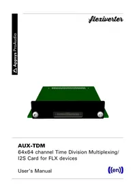


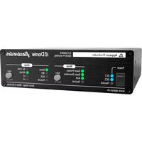
| Product Type | Professional Audio TDM Auxiliary Interface |
| Brand | Appsys ProAudio |
| Model | AUX-TDM |
| Category | Professional Audio Accessory |
| Primary Function | Provides auxiliary TDM bus expansion and routing for digital audio consoles and interfaces |
| TDM Bus Support | 32-channel TDM (Time Division Multiplexed) bus |
| Supported Sample Rates | 44.1 kHz, 48 kHz, 88.2 kHz, 96 kHz, 176.4 kHz, 192 kHz |
| Interface Connector | DB-25 TDM serial connection |
| Power Supply | 12V DC adapter, 500 mA |
| Power Consumption | 5W max |
| Dimensions (W x D x H) | 221 x 120 x 44 mm |
| Weight | 0.9 kg |
| Chassis Material | Sturdy steel with matte finish |
| LED Indicators | Power, Bus Activity, Error status |
| Operating Temperature | 0°C to 45°C |
| Storage Temperature | -20°C to 70°C |
| Regulatory Approvals | CE, RoHS certified |
| Included Accessories | External power adapter, user manual, mounting brackets |
| Maintenance | Clean with dry lint-free cloth; avoid solvents |
| Safety | No internal user-serviceable parts; do not open the chassis |
| Spare Parts | Available from Appsys ProAudio on request |
| Warranty | 2 years limited warranty |
Frequently Asked Questions - AUX-TDM Appsys ProAudio
User questions about AUX-TDM Appsys ProAudio
0 question about this device. Answer the ones you know or ask your own.
Ask a new question about this device
Download the instructions for your Uncategorized in PDF format for free! Find your manual AUX-TDM - Appsys ProAudio and take your electronic device back in hand. On this page are published all the documents necessary for the use of your device. AUX-TDM by Appsys ProAudio.
USER MANUAL AUX-TDM Appsys ProAudio
AUX-TDM
64x64 channel Time Division Multiplexing/ I2S Card for FLX devices
User's Manual
((en))
Table of Contents
1. DESCRIPTION....3
1.1. Box Contents....3
2. INSTALLATION.... 3
2.1. Opening the flexiverter....3
2.2. Flexiverter Inside View....4
2.3. Installing the card....4
3. TDM INTERFACE PINS.... 5
3.1. Pinout (when looking on the card connectors mating face)....5
3.2. Pin descriptions.... 5
3.3. I/O Waveforms.... 6
3.4. Electrical I/O characteristics....6
4. DIP SETTINGS....7
5. SELF-TEST....7
6. SPECIFICATIONS....8
7. APPENDIX....8
7.1. Available AUX cards....8
7.2. Available FLX devices....9
7.3. Warranty....9
7.4. Manufacturer contact....9
7.5. Recycling....10
7.6. Document Revision History....10
7.7. About this document....10
1. DESCRIPTION
The AUX-TDM card provides up to 64x64 channels Time Division Multiplexing (TDM) interface on a 3.3V LVCMOS I/O. It supports four lines of data plus BCLK/LRCLK/MCLK/MUTE outputs, and four lines of data plus BCLK/LRCLK/MUTE inputs.
It can be fitted into every flexiverter (FLX) device for the following purposes:
to use the FLX as standalone converter between the built-in interface and this extension card
to add extra output splits to existing FLX devices by "tapping" channels of another conversion
to add additional channels/protocols to the FLX when it is used in double-flexiverter or flexiverter + multiverter configurations
For a detailed description of possible configurations, please refer to the manual of your base FLX device.
1.1. Box Contents
1 AUX-TDM card
1 Slot cover plate
☐ 34-pin, 0.635mm pitch ribbon cable, 30cm/1ft.
This manual
2. INSTALLATION
2.1. Opening the flexiverter
Required: Torx T10 screwdriver
Power off the device and detach all cables to avoid short-circuit or damage
☐ Detach the device from the rack-mount kit
Remove the four top screws and the top cover by pulling it upwards:


2.2. Flexiverter Inside View

1 Screws for AUX cover plate
2 AUX card connector
2.3. Installing the card
■Remove the screws holding the cover plate, and the blank cover plate
■Insert the AUX card from inside, using the supplied cover plate.
CAUTION: The slot cover must be located on the inside the slot.
Make sure it is correctly fitted to the card connector 2
■Secure the card using two cover screws 1
■The card has been installed correctly if you are able to select an audio routing mode involving AUX (long-press MODE button to enter Route Mode Selection).
3. TDM INTERFACE PINS
3.1. Pinout (when looking on the card connectors mating face)

3.2. Pin descriptions
| Pin | Signal Direction | Description | TDM16 TDM8 TDM4 TDM2 | (Stereo) | |||
| 1, 2, 34 | +3.3V Output Supply | for external circuit (1.5A max). Do not connect when external circuit has its own power supply | |||||
| 4,6,8,10,12,14,16,18, 20,22,24,26,28,30,32 | Ground. All GND lines on the external circuit should be connected to ensure proper shielding between data lines | ||||||
| 3 | BCLK_IN | Input | Bit Clock input. TDM_IN* lines are sampled on the rising edge of this signal | 512* LRCLK_IN | 256* LRLCK_IN | 128* LRCLK_IN | 64* LRCLK_IN |
| 5 | LRCLK_IN | Input | Left/Right Clock input (Wordclock). Must be a 50% duty cycle. First half of the TDM_IN* audio channels are read during LRCLK_IN=0, second half of TDM_IN* channels during LRCLK_IN=1 | ||||
| 7 | TDM_INO Input | Audio data input line 0. Must be 32 bit per channel, left-justified or I2S depending on DIP setting. Only the first 24 bits of each channel are read, the rest is ignored. | Ch 1-16 (512 bit per LRCLK) | Ch 1-8 (256 bit per LRCLK) | Ch 1-4 128 bit per LRCLK) | Ch 1-2 (64 bit per LRCLK) | |
| 9 | TDM_IN1 | Input | Audio data input line 1 | Ch 17-32 | Ch 9-16 | Ch 5-8 | Ch 3-4 |
| 11 | TDM_IN2 | Input | Audio data input line 2 | Ch 33-48 | Ch 17-24 | Ch 9-12 | Ch 5-6 |
| 13 | TDM_IN3 | Input | Audio data input line 3 | Ch 49-64 | Ch 25-32 | Ch 13-16 | Ch 7-8 |
| 15 | MUTE_IN Input | L: Normal operation H: Mute inputs, input data is ignored | |||||
| 17 | Reserved | ||||||
| 19 | BCLK_OUT | Output Bit | Clock output. TDM_OUT* audio data changes on falling edge and is valid on rising edge | 512* LRCLK_OUT | 256* LRLCK_OUT | 128* LRCLK_OUT | 64* LRCLK_OUT |
| 21 | LRCLK_OUT | Output | Left/Right Clock output (Wordclock), 50% duty cycle. First half of the TDM_IN* audio channels are written during LRCLK_IN=0, second half ofTDM_IN* channels during LRCLK_IN=1 | ||||
| 23 | TDM_OUT0 | Output Audio data output line 0.32 bit per channel, left-justified or I2S depending on DIP setting. Output is always 24 bits of audio plus 8 padding bits per channel. Data is valid on the rising edge of BCLK_OUT | Ch 1-16(512 bit per LRCLK) | Ch 1-8(256 bit per LRCLK) | Ch 1-4(128 bit per LRCLK) | Ch 1-2(64 bit per LRCLK) | |
| 25 | TDM_OUT1 | Output Audio data output line 1 Ch 17-32 Ch 9-16 Ch 5-8 Ch 3-4 | |||||
| 27 | TDM_OUT2 | Output Audio data output line 2 Ch 33-48 Ch 17-24 Ch 9-12 Ch 5-6 | |||||
| 29 | TDM_OUT3 | Output Audio data output line 3 Ch 49-64 Ch 25-32 Ch 13-16 Ch 7-8 | |||||
| 31 | MUTE_OUT | Output L: Normal operationH: Output data is invalid and should be muted | |||||
| 33 | MCLK_OUT | Output Master clock output 256*LRCLK | |||||

Do NOT leave any input pins floating. Connect unused pins to GND or VCC, preferably with a 10k resistor.
3.3. I/O Waveforms
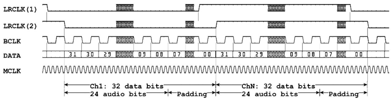
(1) in I2S mode (DIP6: down). Data is delayed by 1 BCLK cycle
(2) in left-justified mode (DIP6: up)
3.4. Electrical I/O characteristics
| Pins Parameter Value Unit | Min Typ Max | ||||
| +3.3V V | CC | 3.135 3.3 | 3.465 V | ||
| ICC | 1.5 | A | |||
| BCLK_IN, LRCLK_IN,TDM_IN*, MUTE_IN | VIH | 2.0 | VCC + 0.5 | V | |
| VIL | -0.5 | 0.8 | V | ||
| BCLK_OUT, LRCLK_OUT, TDM_OUT*,MUTE_OUT, MCLK_OUT | VOH | 3.2 | 3.3 | VCC | V |
| VOL | 0 | 0.1 | V | ||
| I0 ESD protection | ±20 | mA | |||
| All | IEC 61000-4-2 Level 4 ESD Protection±15-kV Contact Discharge / ±15-kV Air-Gap DischargeIEC 61000-4-4 EFT Protection: 80 A (5/50 ns)IEC 61000-4-5 Surge Protection: 3 A (8/20 μs) | ||||
4. DIP SETTINGS
The behavior of the card can be controlled by DIP switches 4..6 on the FLX device. Changing the DIP settings will come immediately into effect.
| TDM mode | 4 5 | *TDM16. Each I/O line carries 16 channels of 32 bit audio data each (512 bits/BCLK cycles per LRCLK) |
| 4 5 | TDM8. Each I/O line carries 8 channels of 32 bit audio data each (256 bits/BCLK cycles per LRCLK) | |
| 4 5 | TDM4. Each I/O line carries 4 channels of 32 bit audio data each (128 bits/BCLK cycles per LRCLK) | |
| 4 5 | TDM2 (Stereo). Each I/O line carries 2 channels of 32 bit audio data ea. (64 bits/BCLK cycles per LRCLK) | |
| Format selection | 6 | *Left-justified, 32 bit per ch (24 bit audio data + 8 bits zero padding) |
| 6 | I2S-Format, 32 bit per ch (24 bit audio data + 8 bits zero padding)Data is delayed by 1 BCLK cycle |
* Default setting
5. SELF-TEST
The card can be tested for correct operation by the user. This is done using the special self-test mode, in which a special random test pattern is output on all channels. This pattern is looped back via an external cable into the corresponding inputs, where it is checked for consistency.
Note: A special loopback plug is required for this. The plug must connect pins 1-9, 2-10, 3-11, 4-12, 5-13, 6-14, 7-15, 8-16.
■Attach the loopback plug
■ Turn off the FLX, and hold down ○ Mode button while switching on again
■ Press Mode again until the "CLOCK" LEDs show "INT/48kHz" in cyan color. The device is now in self-test mode.
■The "AUX" LED in the MODE sections shows the result of the self-test:
red: error/no connection
green (loopback data received ok)
■ Press ○ Mode again or power off the device to exit self-test mode.
6. SPECIFICATIONS
| Parameter Value | |
| Dimensions 118x80mm (WxH) | |
| Weight 40 g | |
| Operating temperature | 0..+55°C, non-condensing |
| Storage temperature | -40..+85°C, non-condensing |
| Inputs Up to 64 channels TDM16 (4 lines with 16ch each)Up to 32 channels TDM8 (4 lines with 8ch each)Up to 16 channels TDM4 (4 lines with 4ch each)Up to 8 channels stereo (4 lines with 2ch each)LRCLK (left/right clock). Polarity: frame starts with falling edgeBCLK (bitclock): Data is sampled on rising edge | |
| Outputs Up to 64 channels TDM16 (4 lines with 16ch each)Up to 32 channels TDM8 (4 lines with 8ch each)Up to 16 channels TDM4 (4 lines with 4ch each)Up to 8 channels stereo (4 lines with 2ch each)LRCLK (left/right clock). frame starts with falling edgeBCLK (bitclock): Data changes on falling edgeMCLK: 256*LRCLK | |
| Cable lengths 30cm / | 1 ft. maximum |
| Sample rates 44.1/48kHz88.2/96kHz (channel count is halved)176.4/192kHz (channel count is quartered) | |
| Latency Interface <> Flexiverter internal: 2 samples | |
7. APPENDIX
7.1. Available AUX cards
At the time of writing (2021-11), the following AUX cards are available. More will come, please check www.appsys.ch for updates.
| Item Description | |
| AUX-ADAT 16x16ch | ADAT I/O (2x Toslink In + 2x out). Supports also S/PDIF |
| AUX-ADAT-64 64x64ch | ADAT I/O (8x Toslink In + 8x out on external breakout box) |
| AUX-AES3 8x8ch AES3 I/O on 1x DB25, fully transformer isolated | |
| AUX-AES67 64x64ch | AES67 network card |
| AUX-DANTE | 64x64ch DANTE network card |
| AUX-MADI-COAX | 64x64ch MADI for coaxial cable (BNC connectors) |
| AUX-MADI-OPTO | 64x64ch MADI optical, SC connector (Multimode 125um 1310 nm) |
| AUX-MADI-SFP 64x64ch MADI for SFP (Small-Factor Pluggable) modules |
| AUX-WORDCLOCK BNC wordclock I/O |
7.2. Available FLX devices
At the time of writing (2024-04), the following FLX devices are available. More will come, please check www.appsys.ch for updates.
| Item Description | |
| FLX-AES3 16x16 channel AES3 flexiverter (with AUX slot) | |
| FLX-AES3/SRC 16x16 channel AES3 flexiverter with optional independent SRCs on the AES3 inputs (with AUX slot) | |
| FLX-AES50 96x96 channel AES50 flexiverter (with AUX slot) | |
| FLX-AES67 64x64 channel AES67 flexiverter (with AUX slot) | |
| FLX-DANTE 64x64 channel DANTE flexiverter (with AUX slot) | |
| FLX-MADI 128x128 channel MADI SFP & MADI coaxial module (with AUX slot) | |
7.3. Warranty
We offer a full two (2) year warranty from the date of purchase. Within this period, we repair or exchange your device free of charge in case of any defect*. If you experience any problems, please contact us first. We try hard to solve your problem as soon as possible, even after the warranty period.
* Not covered by the warranty are any damages resulting out of improper use, willful damage, normal wear-out (especially of the connectors) or connection with incompatible devices.
7.4. Manufacturer contact
Appsys ProAudio
Rolf Eichenseher
Bullingerstr. 63 / BK241
CH-8004 Zürich
Switzerland
www.appsys.ch
info@appsys.ch
Phone: +41 43 537 28 51
Mobile: +41 76 747 07 42
7.5. Recycling

According to EU directive 2002/96/EU, electronic devices with a crossed-out dustbin may not be disposed into normal domestic waste. Please return the products back for environment-friendly recycling, we'll refund you the shipping fees.
7.6. Document Revision History
1: Initial release
7.7. About this document
All trademarks mentioned in this document are property of the respective owners. All information provided here is subject to change without prior notice.
Document Revision: 1 · 2024-05-02
Copyright © 2024 Appsys ProAudio · Printed in Switzerland
IDENT 9.00.xxxxx.00

- AUX-TDM
- TABLE OF CONTENTS
- DESCRIPTION
- INSTALLATION
- TDM INTERFACE PINS
- DIP SETTINGS
- SELF-TEST
- SPECIFICATIONS
- APPENDIX
- BOX CONTENTS
- OPENING THE FLEXIVERTER
- FLEXIVERTER INSIDE VIEW
- INSTALLING THE CARD
- PINOUT (WHEN LOOKING ON THE CARD CONNECTORS MATING FACE)
- PIN DESCRIPTIONS
- I/O WAVEFORMS
- ELECTRICAL I/O CHARACTERISTICS
- AVAILABLE AUX CARDS
- AVAILABLE FLX DEVICES
- WARRANTY
- MANUFACTURER CONTACT
- RECYCLING
- DOCUMENT REVISION HISTORY
- ABOUT THIS DOCUMENT
Brand : Appsys ProAudio
Model : AUX-TDM
Category : Uncategorized