RTH2520 - Thermostat programmable HONEYWELL - Free user manual and instructions
Find the device manual for free RTH2520 HONEYWELL in PDF.
Download the instructions for your Thermostat programmable in PDF format for free! Find your manual RTH2520 - HONEYWELL and take your electronic device back in hand. On this page are published all the documents necessary for the use of your device. RTH2520 by HONEYWELL.
USER MANUAL RTH2520 HONEYWELL
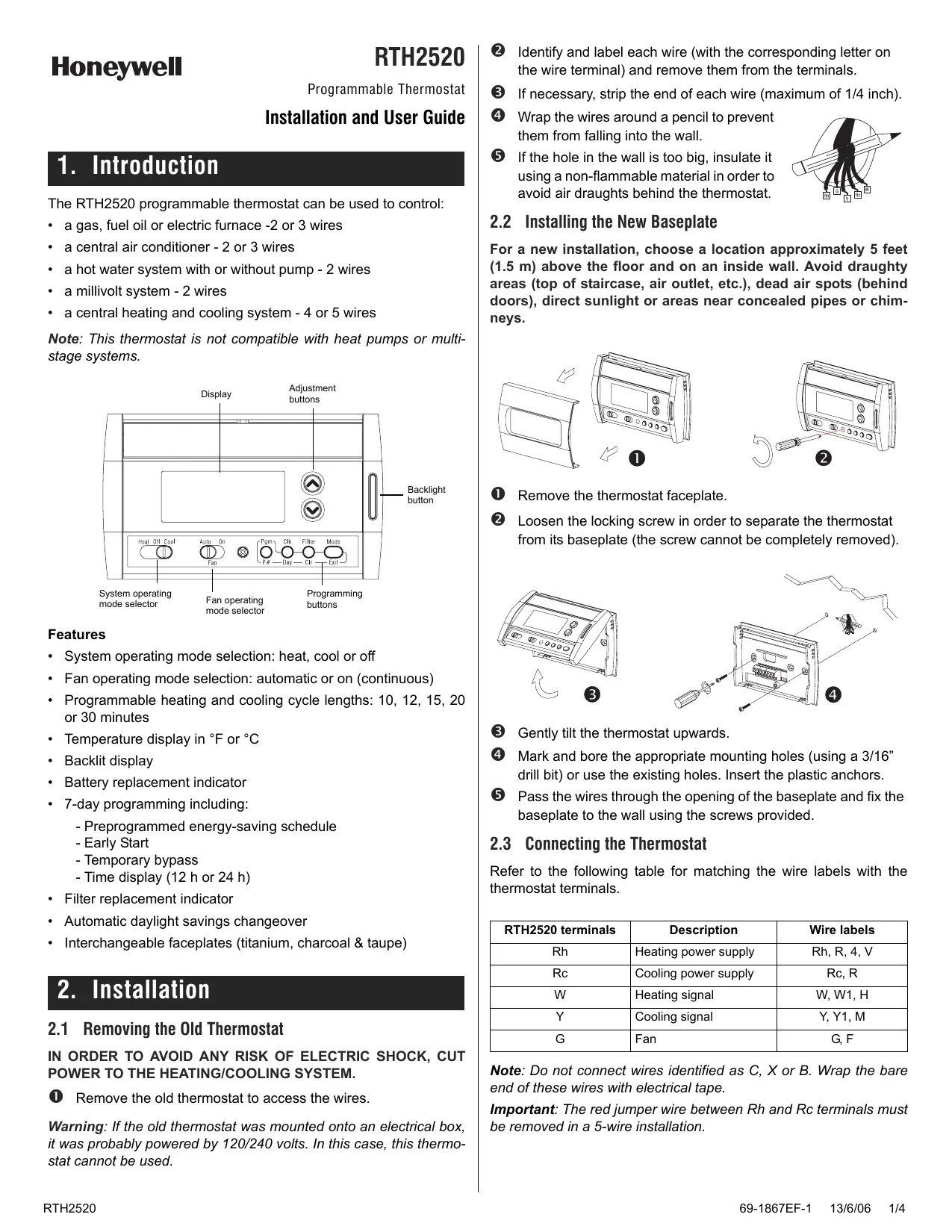
Identify and label each wire (with the corresponding letter on the wire terminal) and remove them from the terminals.
If the hole in the wall is too big, insulate it using a non-flammable material in order to avoid air draughts behind the thermostat.
Installation and User Guide
1. Introduction The RTH2520 programmable thermostat can be used to control:
Wrap the wires around a pencil to prevent them from falling into the wall.
• a gas, fuel oil or electric furnace -2 or 3 wires
2.2 Installing the New Baseplate
• a central air conditioner - 2 or 3 wires
For a new installation, choose a location approximately 5 feet (1.5 m) above the floor and on an inside wall. Avoid draughty areas (top of staircase, air outlet, etc.), dead air spots (behind doors), direct sunlight or areas near concealed pipes or chimneys.
• a hot water system with or without pump - 2 wires • a millivolt system - 2 wires • a central heating and cooling system - 4 or 5 wires Note: This thermostat is not compatible with heat pumps or multistage systems. Display
System operating mode selector
Fan operating mode selector
Remove the thermostat faceplate.
Gently tilt the thermostat upwards.
Pass the wires through the opening of the baseplate and fix the baseplate to the wall using the screws provided.
Loosen the locking screw in order to separate the thermostat from its baseplate (the screw cannot be completely removed).
Features • System operating mode selection: heat, cool or off • Fan operating mode selection: automatic or on (continuous) • Programmable heating and cooling cycle lengths: 10, 12, 15, 20 or 30 minutes • Temperature display in °F or °C • Backlit display • Battery replacement indicator • 7-day programming including: - Preprogrammed energy-saving schedule - Early Start - Temporary bypass - Time display (12 h or 24 h) • Filter replacement indicator • Automatic daylight savings changeover • Interchangeable faceplates (titanium, charcoal & taupe)
2. Installation 2.1 Removing the Old Thermostat IN ORDER TO AVOID ANY RISK OF ELECTRIC SHOCK, CUT POWER TO THE HEATING/COOLING SYSTEM.
Remove the old thermostat to access the wires.
Warning: If the old thermostat was mounted onto an electrical box, it was probably powered by 120/240 volts. In this case, this thermostat cannot be used. RTH2520
Mark and bore the appropriate mounting holes (using a 3/16” drill bit) or use the existing holes. Insert the plastic anchors.
2.3 Connecting the Thermostat Refer to the following table for matching the wire labels with the thermostat terminals. RTH2520 terminals
Heating power supply
Cooling power supply
W, W1, H Y Cooling signal
Rc, R G, F Note: Do not connect wires identified as C, X or B. Wrap the bare end of these wires with electrical tape. Important: The red jumper wire between Rh and Rc terminals must be removed in a 5-wire installation.
2.4 Setting JP2 Jumper
2.3.1 2-wire Heating
The jumper specifies how the fan will operate when it is placed in automatic mode (see section 3.2).
2.3.2 2-wire Cooling
HG Leave the jumper in this position if you have a gas or oil heating system.
HE Move the jumper to this position if you have an electric heating system.
2.5 Installing the Batteries Jumper Cool relay
2.3.3 3-wire Heating
Jumper Heat relay Fan relay
2.3.4 3-wire Cooling
Gently pull out the battery cover. Install the batteries as shown. Observe the polarity. Reinstall the battery cover. You will hear a clicking sound.
After the batteries are installed, the thermostat performs a sequence of tests for approximately 5 seconds. Afterwards, the screen displays the actual temperature. It is normal that the displayed temperature be higher than the ambient temperature if you are holding the thermostat. Once installed on the wall, the thermostat will display the ambient temperature. By default, the setpoint is 70°F (21°C). The time and day settings flash to indicate that they must be set (see section 5.1).
2.6 Completing the Installation
Cool relay Fan relay
2.3.5 4-wire Heating and Cooling
Jumper Heat relay Cool relay
Once the baseplate and the batteries are installed, mount the thermostat on the baseplate.
Secure the thermostat using the locking screw and install the faceplate.
Apply power back to the system.
2.3.6 5-wire Heating and Cooling
Note: Remove the red jumper wire between terminals Rc and Rh.
Use this selector switch to place the system in Heating mode (HEAT) or Cooling mode (COOL), or to set both modes to Off. Note: When you place the thermostat in Cooling mode, you might need to wait up to five minutes before cooling can start. This is a safety feature for the compressor. will flash on the screen during the delay. 69-1867EF-1
3.2 Fan Operating Mode
After replacing the batteries, set the time, day and date (see sections 5.1 and 5.2). However, the temperature and program settings are saved and do not need to be re-entered.
Use the selector switch to set the fan to automatic mode (AUTO) or continuous mode (ON).
Warning: Before removing the batteries, place the system switch on the thermostat to Off. Otherwise, the heating/cooling unit might still be running even after the batteries are removed.
Note: This switch is not used in a 2-wire installation as the fan is not connected to the thermostat in this type of installation.
AUTO ON The fan operates only when the heating or cooling system is On (typical setting). The fan operates continuously. Use this setting to improve air circulation and air cleaning.
4. Configuration Menu DISPLAY
3.3 Displaying the Temperature
°C or °F The actual temperature is normally displayed. To view the setpoint, press once on one of the buttons. The setpoint is displayed for 5 seconds along with the icon.
Note: Pressing either of the change the setpoint.
buttons more than once will
3.4 Setting the Temperature Press one of the played.
buttons until the desired temperature is dis-
3.5 Backlight The display illuminates for 12 seconds when the backlight button or either of the buttons is pressed.
3.6 Thermostat Control Mode 3.6.1 Manual/Permanent Hold Mode Maintains the temperature at a fixed setpoint. To place the thermostat in this mode, press [ Mode ]. The house icon will disappear.
3.6.2 Programmable Mode Maintains the temperature according to the energy-saving schedule. To place the thermostat in this mode, press [ Mode ]. The current period will be displayed. The four possible periods are:
Temporary Bypass If you modify the setpoint (using the buttons) when the thermostat is in Programmable mode, the thermostat will use the new setpoint for the next 2 hours. The house icon flashes during the bypass. Afterwards the thermostat will return to the temperature setting of the period currently underway.
After 500 hours of operation, an icon appears to indicate that the filter needs replacement. Once the filter is replaced, press [ Filter ] for 3 seconds to remove the icon and reset the counter.
3.8 Battery Replacement Indicator Install fresh batteries immediately when the icon starts flashing. The icon flashes for 120 days before the batteries are depleted. You should replace batteries once a year or before leaving home for more than a month even if the icon has not appeared.
When Early Start is On, the thermostat determines when to start heating or cooling so that the desired temperature is reached at the set time. 2 When this function is On, the thermostat automatically switches to daylight savings time on the second Sunday of March and to normal time on the first Sunday of November (see section 5.2). 3 Use the Heat/Cool selector switch to switch between the heating parameter and the cooling parameter. 4 For optimal heating control, use the setting that matches your system as follows: 2=30 min (steam, gravity), 3=20 min (hot water, 90%+ high-efficiency furnace), 4=15 min (gas or oil), 5=12 min (alternate setting for gas or oil), 6=10 min (electric). 5 The corresponding cooling cycle lengths are: 2=30 min., 3=20 min., 4=15 min., 5=12 min., 6=10 min.
To see the default program settings, see section 5.3.
5. Programming 5.1 Setting the Time and Day
Press [ Clk ]. The hour flashes.
Press [ Exit ] to exit.
Press [ Clk ]. The minutes flash. Set the minutes using
Press [ Clk ]. The day flashes. Set the day using . (MO: Monday, TU: Tuesday, WE: Wednesday, TH: Thursday, FR: Friday, SA: Saturday and SU: Sunday).
5.2 Setting the Date The date is needed for automatic daylight savings changeover.
Press [ Clk ] for 3 seconds to display the year.
Set the year using play the month.
Set the month using play the date.
6. Technical Specifications
and press [ Clk ] to dis-
and press [ Clk ] to dis-
Power supply: 2 AA batteries Maximum load: 1 A @ 24 VAC per output Setpoint range (heating): 41 to 82°F (5 to 28°C)
Setpoint range (cooling): 59 to 95°F (15 to 35°C)
Press [ Exit ] to exit.
Display range: 23 to 122°F (-5 to 50°C)
5.3 Energy-saving Schedule
Storage temperature: -2 to 122°F (-20 to 50°C)
Your thermostat is preprogrammed with an energy-saving schedule. The schedule automatically controls your heating or cooling system by switching from one setpoint to the next according to the preset times.
Temperature display resolution: 1°F (0.5°C) Accuracy: ± 1°F (0.5°C) Heating/cooling cycle lengths: 10, 12, 15, 20 or 30 minutes (programmable) Compressor short-cycle protection (minimum off time): 5 minutes Data memory: non-volatile
Default program settings Heating
MO TU WE TH FR SA SU
5.4 Modifying the Schedule You can program up to 4 periods per day, each period having its own temperature settings. You can have a different program for each day of the week. For each period, you can set the start time, the heating setpoint and the cooling setpoint.
Press [ Pgm ]. The period 1 settings are displayed. Period start time Temperature setting
Program days Period number
Note: During programming, to skip a period, press [ CLR ] while the period is displayed. For example, in the predefined energy-saving schedule, periods 2 and 3 have been skipped for Saturday and Sunday.
Press [ Day ] to select the day. Press for 3 seconds to select all 7 days. (MO: Monday, TU: Tuesday, WE: Wednesday, TH: Thursday, FR: Friday, SA: Saturday and SU: Sunday).
Set the time (in increments of 15 minutes) using the tons.
Press [ P# ]. The heating or cooling setpoint flashes depending on the position of the Heat/ Cool selector.
Set the desired temperature for the displayed period using the buttons.
Use the Heat/Cool selector to switch to the other mode (e.g., if you were in Heating mode, switch to Cooling mode). The setpoint for that mode flashes.
Set the desired temperature using the
Press [ P# ] to go to the next period. Repeat steps 2 to 8 for the remaining periods. Press [ Exit ] to exit.
Dimensions: 5 in. x 3 in. x 1 in. (127 mm x 75 mm x 28 mm)
Honeywell warrants this product, excluding battery, to be free from defects in the workmanship or materials, under normal use and service, for a period of one (1) year from the date of purchase by the consumer. If at any time during the warranty period the product is determined to be defective or malfunctions, Honeywell shall repair or replace it (at Honeywell's option). If the product is defective, (i) return it, with a bill of sale or other dated proof of purchase, to the place from which you purchased it, or (ii) call Honeywell Customer Care at 1-800-468-1502. Customer Care will make the determination whether the product should be returned to the following address: Honeywell Return Goods, Dock 4 MN10-3860, 1885 Douglas Dr N, Golden Valley, MN 55422, or whether a replacement product can be sent to you. This warranty does not cover removal or reinstallation costs. This warranty shall not apply if it is shown by Honeywell that the defect or malfunction was caused by damage which occurred while the product was in the possession of a consumer. Honeywell's sole responsibility shall be to repair or replace the product within the terms stated above. HONEYWELL SHALL NOT BE LIABLE FOR ANY LOSS OR DAMAGE OF ANY KIND, INCLUDING ANY INCIDENTAL OR CONSEQUENTIAL DAMAGES RESULTING, DIRECTLY OR INDIRECTLY, FROM ANY BREACH OF ANY WARRANTY, EXPRESS OR IMPLIED, OR ANY OTHER FAILURE OF THIS PRODUCT. Some states do not allow the exclusion or limitation of incidental or consequential damages, so this limitation may not apply to you. THIS WARRANTY IS THE ONLY EXPRESS WARRANTY HONEYWELL MAKES ON THIS PRODUCT. THE DURATION OF ANY IMPLIED WARRANTIES, INCLUDING THE WARRANTIES OF MERCHANTABILITY AND FITNESS FOR A PARTICULAR PURPOSE, IS HEREBY LIMITED TO THE ONE-YEAR DURATION OF THIS WARRANTY. Some states do not allow limitations on how long an implied warranty lasts, so the above limitation may not apply to you. This warranty gives you specific legal rights, and you may have other rights which vary from state to state. If you have any questions concerning this warranty, please write Honeywell Customer Relations, 1985 Douglas Dr, Golden Valley, MN 55422 or call 1800-468-1502. In Canada, write Retail Products ON15-02H, Honeywell Limited/Honeywell Limitée, 35 Dynamic Drive, Scarborough, Ontario M1V4Z9.
8. Service If you have any questions about the operation of your thermostat, please go to http://yourhome.honeywell.com, or call Honeywell Customer Care toll-free at 1-800-468-1502. As an ENERGY STAR® partner, Honeywell has determined that this product meets the ENERGY STAR guidelines for energy efficiency.
W Signal - chauffage