
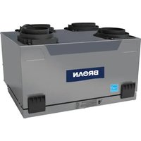
B230H75RT - Air conditioner BROAN - Free user manual and instructions
Find the device manual for free B230H75RT BROAN in PDF.


| Product type | Air conditioner |
| Brand | Broan |
| Model | B230H75RT |
| Installation type | Window air conditioner |
| Cooling capacity | 23,000 BTU/h |
| Power supply | 230 V / 60 Hz |
| Energy consumption | 2,200 W |
| Refrigerant | R410A |
| Dimensions (H x W x D) | 60 cm x 70 cm x 50 cm |
| Weight | 55 kg |
| Operating modes | Cool, fan, dehumidification |
| Thermostat | Adjustable with digital display |
| Timer | Programmable from 1 to 24 hours |
| Remote control | Included |
| Air filter | Washable and reusable |
| Fan speeds | 3 speeds |
| Noise level | ~60 dB |
| Maintenance | Clean the filter every 2 weeks |
| Safety | Overheating protection |
| Spare parts | Available: filters, remote control |
Frequently Asked Questions - B230H75RT BROAN
User questions about B230H75RT BROAN
0 question about this device. Answer the ones you know or ask your own.
Ask a new question about this device
Download the instructions for your Air conditioner in PDF format for free! Find your manual B230H75RT - BROAN and take your electronic device back in hand. On this page are published all the documents necessary for the use of your device. B230H75RT by BROAN.
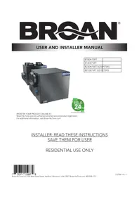
USER MANUAL B230H75RT BROAN
| B180H75RT | |
| B180E75RT | |
| B230H75RT B230 | H75RS |
| B210E75RT B210 | E75RS |

REGISTER YOUR PRODUCT ONLINE AT:
Broan-NuTone.com/en-us/home/customer-service/product-registration
For additional information, visit Broan-NuTone.com
INSTALLER: READ THESE INSTRUCTIONS SAVE THEM FOR USER
Please take note that this manual uses the following symbols to emphasize particular information:
WARNING
Identifies an instruction which, if not followed, might cause serious personal injuries including possibility of death.
CAUTION
Denotes an instruction which, if not followed, may severely damage the unit and/or its components.
NOTE: Indicates supplementary information needed to fully complete an instruction.
LIMITATION
For residential (domestic) installation only. Installation work and electrical wiring must be done by a qualified person in accordance with all applicable codes and standards, including fire-rated construction codes and standards.
⚠ WARNING
TO REDUCE THE RISK OF FIRE, ELECTRIC SHOCK, OR INJURY TO PERSON(S) OBSERVE THE FOLLOWING:
- Use this unit only in the manner intended by the manufacturer.
- Before servicing or cleaning this unit, disconnect power cord from electrical outlet.
- This unit is not designed to provide combustion and/or dilution air for fuel-burning appliances.
- When cutting or drilling into a wall or ceiling, do not damage electrical wiring and other hidden utilities.
- Do not use this unit with any solid-state speed control device other than those specified in section 3.1.
- This unit must be grounded. The power supply cord has a 3-prong grounding plug for your personal safety. It must be plugged into a mating 3-prong grounding receptacle, grounded in accordance with the national electrical code and local codes and ordinances. Do not remove the ground prong. Do not use an extension cord.
- Do not install in a cooking area or connect directly to any appliances.
- Do not use to exhaust hazardous or explosive materials and vapors.
- When performing installation, servicing or cleaning this unit, it is recommended to wear safety glasses and gloves.
- When applicable local regulation comprises more restrictive installation and/or certification requirements, the aforementioned requirements prevail on those of this document and the installer agrees to conform to these at his own expense.
CAUTION
- To avoid prematurely clogged filters, turn the unit OFF during construction or renovation.
- Please read specification label on product for further information and requirements.
- Be sure to duct air outside – Do not intake/exhaust air into spaces within walls or ceiling or into attics, crawl spaces, or garage. Do not attempt to recover the exhaust air from a dryer or a range hood.
- Intended for residential installation only in accordance with the requirements of NFPA 90B (for a unit installed in U.S.A.) or Part 9 of the National Building Code of Canada (for a unit installed in Canada).
- Do not run any air ducts directly above or within 2 ft. of a furnace or its supply plenum, boiler, or other heat producing appliance. If a duct has to be connected to the furnace return plenum, it must be connected 10 ft. away from plenum connection to the furnace.
- The ductwork is intended to be installed in compliance with all applicable local and national codes.
- When leaving the house for a long period of time (more than two weeks), a responsible person should regularly check if the unit operates adequately.
- If the ductwork passes through an unconditioned space (e.g.: attic), the unit must operate continuously except when performing maintenance and/or repair. Also, the ambient temperature of the house should never drop below 65°F (18°C) .
- At least once a year, the unit mechanical and electronic parts should be inspected by qualified service personnel.
- Do not use your unit during construction or renovation of your house or when sanding drywall. Certain types of dust and vapors may damage your system.
- Make sure at all times that the outside intake and exhaust hoods are free from any snow during the winter season. It is important to check your unit during a big snow storm, so it doesn't draw in any snow. If this is the case, please turn the unit OFF for a few hours.
- Since the electronic control system of the unit uses a microprocessor, it may not operate correctly because of external noise or very short power failure. If this happens, unplug the unit and wait approximately 10 seconds. Then, plug the unit in again.
- Do not make excessive use of fragrance appliances or chemicals since some may damage the unit components material.
TABLE OF CONTENTS
1. TECHNICAL DATA ....4
1.1 AIR DISTRIBUTION (NORMAL OPERATION) 4
2. INSTALLATION......4
2.1 LOCATING AND MOUNTING THE UNIT 4
2.2 INSTALLING THE DUCTWORK AND THE REGISTERS....6
2.2.1 FULLY DUCTED SYSTEM (T-1) (THIS CONFIGURATION ALLOWS RECIRCULATION MODE TO OPERATE.)....6
2.2.2 EXHAUST DUCTED SYSTEM (T-2) (THIS CONFIGURATION ALLOWS RECIRCULATION MODE TO OPERATE.) 6
2.2.3 SIMPLIFIED INSTALLATION (T-4) (THIS CONFIGURATION DOES NOT ALLOW RECIRCULATION MODE TO OPERATE.) 7
2.3 CONNECTING THE DRAIN (HRV ONLY) 8
2.4 EXTERIOR HOODS INSTALLATION / LOCATION 9
2.5 CONNECTING THE DUCTS TO THE UNIT 10
2.5.1 DUCTS CONNECTION 11
3. CONNECTIONS....12
3.1 ELECTRICAL CONNECTION TO OPTIONAL MAIN WALL CONTROL 12
3.1.1 ELECTRICAL CONNECTION TO SPEED, DEHUMIDISTAT OR AUTOMATIC OPTIONAL MAIN WALL CONTROL....12
3.1.2 ELECTRICAL CONNECTION TO ADVANCED OPTIONAL MAIN WALL CONTROL.... 12
3.2 ELECTRICAL CONNECTION TO OPTIONAL AUXILIARY WALL CONTROL 13
3.2.1 ELECTRICAL CONNECTION TO 20-40-60 OPTIONAL AUXILIARY WALL CONTROL....13
3.2.2 ELECTRICAL CONNECTION TO DRY CONTACT OPTIONAL AUXILIARY WALL CONTROL (E.G. CRANK TIMER)....13
3.3 CONNECTION TO THE CENTRAL FORCED-AIR SYSTEM 14
3.3.1 UNIT OPERATION USING A DRY CONTACT CONNECTION....14
3.3.2 UNIT INTERCONNECTION WITH CENTRAL FORCED-AIR SYSTEM (R/C/G/GF) 14
3.3.3 SYNCHRONIZATION WITH CENTRAL FORCED-AIR SYSTEM FUNCTION....14
4. WIRING DIAGRAM ....15
5. NAVIGATION ON LCD SCREEN....16
5.1 LCD SCREEN 17
5.2 UNIT FIRST BOOT....17
5.3 SETTINGS MODIFICATION....17
5.3.1 PROCEDURE TO MODIFY MIN CFM SETTING....17
5.3.2 PROCEDURE TO MODIFY MAX CFM SETTING....17
5.3.3 PROCEDURE TO MODIFY OPTIONS SETTING....17
5.3.4 PROCEDURE TO MODIFY INDEPENDENT AIRFLOWS SETTING....17
5.4 FACTORY SETTINGS RESET 18
6. USING THIS UNIT ....18
6.1 YOUR VENTILATION SYSTEM 18
6.2 INTEGRATED CONTROL....18
6.3 AHU MODE DISPLAY 18
7. SERVICE PARTS....19
8. INSTALLER'S TROUBLESHOOTING ....21
8.1 ELECTRONIC PROTECTION TO PREVENT ABNORMAL HIGH STATIC PRESSURE....23
9. MAINTENANCE....24
9.1 QUARTERLY 24
9.2 ANNUAL (AT FALL) 25
10. USER'S TROUBLESHOOTING ....25
11. WARRANTY 26
Consumer Information
A. To ensure quiet operation of the H/ERV, each product model must be installed using sound attenuation techniques appropriate for the installation.
B. The way your heat/energy-recovery ventilator is installed can make a significant difference to the electrical energy you use. To minimize the electricity use of the heat/energy-recovery ventilator, a stand-alone fully ducted installation is recommended. If you choose a simplified installation that operates your furnace air handler for room-to-room ventilation, an electrically efficient furnace that has an electronically commutated (EC) variable speed blower motor will minimize your electrical energy consumption and operating cost.
C. Installation of a user-accessible control with your product model will improve comfort and may significantly reduce the product model's energy use.
1. TECHNICAL DATA
1.1 AIR DISTRIBUTION (NORMAL OPERATION)


NOTE: The dimensions, performance charts and specifications are listed on the specification sheets of the unit. Visit our website at Broan-NuTone.com.
2. INSTALLATION
WARNING
The wearing of safety glasses and gloves is recommended when installing, maintaining or cleaning the unit to reduce the risk of injury that could be caused by the presence of thin metal and/or high moving parts.
CAUTION
Make sure that no piece of mineral wool will enter in the unit during installation. Otherwise, this could reduce airflow and generate vibrations and noise in the unit.
2.1 LOCATING AND MOUNTING THE UNIT
Choose an appropriate location for the unit:
- Within an area of the house where the ambient temperature is kept between 50°F and 149°F ;
- Away from living areas (dining room, living room, bedroom), if possible;
- So as to provide easy access to the interior cabinet for maintenance, and to the control panel on the side of the unit;
- Close to an exterior wall, so as to limit the length of the insulated flexible ducts to and from the unit;
- HRV units only: close to a drain. If no drain is close by, use a pail to collect run-off;
- Away from hot chimneys, electrical panel and other fire hazards;
- Within 6 feet of a power source (standard outlet).
2.1 LOCATING AND MOUNTING THE UNIT (CONT.)
Suspended to the joists or trusts:
- Slightly bend the brackets on the unit to insert the provided chains.
- Hang the unit to the joists (or trusts) using the chains. Springs are not required.
• Always make sure that the unit is no more than 1/4" off level.

OR
Wall mounted:
- Choose the appropriate location(s) for the mounting brackets (see illustration below) according to stud(s) position.
- Insert the provided brackets under the unit frame (see illustration hereafter).
- Fix the bracket using the screw no. 8 x 3/8".
- Using the 4 no. 8 × 11/2 " screws provided, secure the unit to the wall making sure that the 4 screws engage into a stud.
• Always make sure that the unit is no more than 1/4" off level.

NOTE: Keep 3" clearance on electrical box side for cooling and servicing.
INSTALLATION WITH 2 BRACKETS INSTALLATION WITH 4 BRACKETS


2.2 INSTALLING THE DUCTWORK AND THE REGISTERS
WARNING
Never install a stale air exhaust register in a room where there is a combustion device, such as a furnace, gas water heater, fireplace or any appliance or equipment that can generate gaseous contaminants, or pollutants. The negative pressure this could create in the room may impair proper evacuation of the gas or pollutants, which may have severe health consequences.
CAUTION
If ducts have to go through an unconditioned space (e.g.: attic), always use insulated ducts to prevent condensation formation inside and outside ducts, which could cause material damage and/or mold growth. Moreover, if fresh air to building duct and/or stale air from building duct goes/go through an unconditioned space, the unit must be set to operate continuously in cold conditions (below 10° C/50°F). Continuous air movement inside ducts will prevent condensation formation. The unit can be stopped temporarily for maintenance and/or repair purposes in such conditions.
2.2.1 FULLY DUCTED SYSTEM (T-1) (THIS CONFIGURATION ALLOWS RECIRCULATION MODE TO OPERATE.)
STALE AIR FROM BUILDING:
• Install registers in areas where contaminants and humidity are produced: kitchen, bathrooms, laundry room, etc.
• Install registers on an interior wall, 6 to 12 inches away from the ceiling OR in the ceiling.
• Install the kitchen register at least 4 feet away from the range.
- Bathroom fans and range hoods can be used to better exhaust stale air.
• Homes with more than one level require at least one exhaust register at the highest level.
FRESH AIR TO BUILDING:
• Install registers in bedrooms, dining room, living room and basement.
• Install registers in the ceiling OR high on the walls with the airflow directed towards the ceiling.
- If a register must be installed in the floor, direct the airflow up the wall.

NOTE: For this type of configuration, the T-1 option must be selected on the LCD screen when auto-balancing the unit (see section 5.2).
2.2.2 EXHAUST DUCTED SYSTEM (T-2) (THIS CONFIGURATION ALLOWS RECIRCULATION MODE TO OPERATE.)
WARNING
Duct connection to the central forced-air system can be regulated by some codes and standards. It is your responsibility to consider and comply with your local requirements to avoid any non-compliance.
STALE AIR FROM BUILDING:
Same as for Fully Ducted System, described on point 2.2.1.
FRESH AIR TO BUILDING:
- Connect the fresh air distribution duct of the unit to the central forced-air system return duct at least 10 feet away from the central forced-air system (A+B) * .
* This 10-ft. distance applies only in areas where the outside temperature falls below the freezing point (32°F).
NOTE: The central forced-air system blower operation can be synchronized with the unit (see section 3.3). It is recommended, but not essential that the central forced-air system blower runs when the unit is in operation.
NOTE: For this type of configuration, the T-2 option must be selected on the LCD screen when auto-balancing the unit (see section 5.2).

ALTERNATE INSTALLATION (T-3) (THIS CONFIGURATION ALLOWS RECIRCULATION MODE TO OPERATE.)
Unit should be synchronized with central forced-air system operation to avoid condensation and mold growth in central forced-air system distribution ducting if cooling mode of central forced-air system is used.
CAUTION
This configuration is not recommended with high velocity central forced-air system. High pressures produced by these systems could affect unit proper operation and generate errors.
NOTE: For this type of configuration, the T-3 option must be selected on the LCD screen when auto-balancing the unit (see section 5.2).

2.2.3 SIMPLIFIED INSTALLATION (T-4) (THIS CONFIGURATION DOES NOT ALLOW RECIRCULATION MODE TO OPERATE.)
CAUTION
The central forced-air system must be synchronized with the unit since fresh air evacuation and distribution come from the same section. The central forced-air system must operate to avoid fresh air to be directly drawn by the evacuation, which would reduce significantly fresh air supply to the building. See section 3.3 for ducting.

WARNING
Duct connection to the central forced-air system can be regulated by some codes and standards. It is your responsibility to consider and comply with your local requirements to avoid any non-compliance.
Fresh air and exhaust air flow through the central forced-air system ducts, which simplifies the installation.
The use of bathroom fans and a range hood is suggested to exhaust stale air.
STALE AIR FROM BUILDING:
Connect the stale air intake port of the unit to the central forced-air system return duct at least 3 feet ahead of the fresh air distribution from the unit.
FRESH AIR TO BUILDING:
Connect the fresh air distribution duct of the unit to the central forced-air system return duct at least 10 feet away from the central forced-air system (A+B) 4 .
* This 10-ft. distance applies only in areas where the outside temperature falls below the freezing point (32°F).
NOTE: For this type of configuration, the T-4 option must be selected on the LCD screen when auto-balancing the unit (see section 5.2).

ALTERNATE INSTALLATION (T-5) (THIS CONFIGURATION DOES NOT ALLOW RECIRCULATION MODE TO OPERATE.)
Unit should be synchronized with central forced-air system operation to avoid condensation and mold growth in central forced-air system distribution ducting if cooling mode of central forced-air system is used.
CAUTION
This configuration is not recommended with high velocity central forced-air system. High pressures produced by these systems could affect unit proper operation and generate errors.
NOTE: For this type of configuration, the T-5 option must be selected on the LCD screen when auto-balancing the unit (see section 5.2).

2.3 CONNECTING THE DRAIN (HRV ONLY)
CAUTION
Install the drain hose included and run it to a drain or a pail. This unit may generate a large amount of water in cooler weather. It is necessary to install the drain hose properly to prevent water damage and/or material damage.
- Cut the appropriate length of drain tubing (see illustration at right).
- Connect the tubing to the provided adaptor.
- Make a water trap loop in the tube to prevent the unit from drawing unpleasant odors from the drain source.
- Add water in the loop to prevent noise or hiss.
- Make sure there is a distance of at least 2" between the unit and the tubing loop (see illustration at right).
• Using tie wraps provided, attach the tubing as illustrated. - Run the tube to the floor drain or to an alternate drain pipe or pail.
- IMPORTANT: If using a pail to collect water, place the tube end approximately 1" inside the pail in order to prevent water from being drawn back up into the unit.

2.4 EXTERIOR HOODS INSTALLATION / LOCATION
WARNING
Make sure intake hood is located at least 10 feet away from any of the following:
- Dryer exhaust, central vacuum vent
• Gas meter exhaust, gas barbecue-grill - Any exhaust vents or chimney from a combustion source
- Garbage bin and any other source of contamination such as parking lots, streets
For multifamily buildings only:
Make sure exhaust hood is located at least 3 feet away from any of the following:
- Property lines
- Operable openings into buildings (door, window)
- Intake and exhaust hood(s) shall be protected with corrosion-resistant screens, louvers or grilles having openings not less than 1/4 inch and not larger than 1/2 inch.
• Install hood(s) at least at 18 inches away from the ground OR depth of expected snow accumulation, whichever is greater.
To minimize cross-contamination of exhausted stale air into the fresh air intake:
Single detached, attached homes and townhouses:
- Maintain a 6 feet minimum separation distance between outdoor air intake and exhaust hoods OR use an approved factory-built intake/exhaust combination termination fitting.
Multifamily buildings:
- Maintain a 10 feet minimum separation distance between outdoor air intake and exhaust hoods OR use an approved factory-built intake/exhaust combination termination fitting.
Ignoring these recommendations could significantly degrade the quality of the incoming air which, in some cases, could result in health consequences. In the event of a conflict between our recommendations and any local requirements, the latter shall have priority.
Refer to illustration below for an example of proper connection method of the insulated ducts to the hoods. An "Anti-Gust Intake Hood" should be installed in regions where snow is expected.

2.5 CONNECTING THE DUCTS TO THE UNIT
CAUTION
- If ducts have to go through an unconditioned space (e.g.: attic), always use insulated ducts to prevent condensation formation inside and outside ducts, which could cause material damage and/or mold growth.
- Do not use screws to connect the ducts or transitions to the ports so as not to interfere with ports inner dampers operation. A non-functioning damper could freeze the unit, which could cause damages.
INSULATED FLEXIBLE DUCTS
Use the following procedure to connect the insulated flexible ducts to the ports of the unit (exhaust to outside and fresh air from outside).
- Expose the flexible duct by pulling back the insulation, and place it over the inner port ring.
- Attach the flexible duct to the port using a tie wrap.
- Seal the joint using duct tape.
- Pull the insulation and vapor barrier over the joint, tuck them between the inner and outer rings of the double collar and fasten them in place using duct tape.
CAUTION
The vapor barrier should remain intact and free of cracks or openings. An opening could produce condensation inside or outside duct, which could cause material damage and/or mold growth in the long run.

VJ0157


TRANSITIONING TO 8-IN. DUCTS
If using 8-in. ducts, install 6-in. to 8-in. transitions on the ports, and secure using duct tape only. If rigid ducting is used, install a 12-in. section of flexible duct between the transition and the rigid ducting (see above).
Rigid ducts
To prevent potential water leakage in cold side rigid ducting insulation, seal all rigid ducting joints with duct tape.
To avoid transmission of vibrations, always use a 12-inch section of flexible duct to connect rigid ducts to the unit. To connect insulated rigid ducts to the unit (cold side) using insulated flexible ducts, follow instructions in section 2.4. To connect regular rigid ducts (warm side) to the unit using non-insulated flexible ducts, use a tie wrap.
NOTE: It is recommended to use 8" ducting instead of 6" ducting if required airflow is over 200 CFM and long run of ducting or high quantity of elbows is used. It will prevent having too high static pressure in the ducting.
2.5.1 DUCTS CONNECTION
IMPORTANT: Make sure to connect ducting as illustrated below to get airflows reading accuracy. Correct installation will also allow proper drainage of water that may accumulate in ducting.
CORRECT INSTALLATION

VD0489
CAUTION
Ducting must not be too crushed. Otherwise, airflows reading accuracy will be affected.
CAUTION
Insulated ducts must have the same diameter as the ports to ensure proper drainage of water that may accumulate in ducts.

NOTE: Route ducts as straight as possible, minimize the number of elbows and design and install ducts in accordance with ACCA's Manual D.
3. CONNECTIONS
3.1 ELECTRICAL CONNECTION TO OPTIONAL MAIN WALL CONTROL
WARNING
Always disconnect the unit before making any connections. Failure to cut power could result in electrical shock or damage to the wall control or electronic module inside the unit.
CAUTION
Never install more than one optional main wall control per unit. Make sure that the wires do not short-circuit between themselves or by touching any other components on the wall control. Avoid poor wiring connections. To reduce the risk of electrical interference (noise), do not run wall control wiring next to control contactors or near light dimming circuits, electrical motors, dwelling/building power or lighting wiring or power distribution panel.

Use the terminal connector included to perform the electrical connection for optional main wall control. Check if all wires are correctly inserted in their corresponding holes in the terminal connector. Use screws to fix wires in the terminal connector.
Once the wall control connections have been made, insert the terminal connector in the electrical compartment.
NOTE : For information about the operation of the wall control, refer to the corresponding Installation and User Guide, available at Broan-NuTone.com.
3.1.1 ELECTRICAL CONNECTION TO SPEED, DEHUMIDISTAT OR AUTOMATIC OPTIONAL MAIN WALL CONTROL

3.1.2 ELECTRICAL CONNECTION TO ADVANCED OPTIONAL MAIN WALL CONTROL

3.2 ELECTRICAL CONNECTION TO OPTIONAL AUXILIARY WALL CONTROL
3.2.1 ELECTRICAL CONNECTION TO 20-40-60 OPTIONAL AUXILIARY WALL CONTROL

VC0243
When configurating OVR option on the LCD screen, choose among these 3 configurations: BAL (the unit remains balanced while providing maximum airflow), PER (the unit is slightly unbalanced since the distribution motor is in MAX speed while allowing maximum exhaust ventilation) and DIS (the unit is unbalanced since air distribution is constant despite a higher need in exhaust ventilation).
NOTE : The auxiliary wall control can be used with a 3-wire connection by removing the LED signals. This optional wiring will not allow an installation with more than 1 auxiliary wall control to properly synchronize their LEDs on an event requested from a peer. Only the auxiliary wall control having requested the timer event will have the LEDs updated accordingly.
3.2.2 ELECTRICAL CONNECTION TO DRY CONTACT OPTIONAL AUXILIARY WALL CONTROL (E.G. CRANK TIMER)

VC0256
WARNING
A miswiring that sends a 24 VAC signal to the 6-position terminal block (OVR, LED, 12V, D-, D+, GND) could permanently damage the control circuit. Verify carefully wire connections before powering-up the unit.
3.3 CONNECTION TO THE CENTRAL FORCED-AIR SYSTEM
WARNING
Never connect a 120-volt AC circuit to the terminals of the central forced-air system interlock (standard wiring). Only use the low voltage class 2 circuit of the central forced-air system blower control. The unit is designed for low voltages only. Connecting the unit on 120-volt circuit would damage it instantly.
3.3.1 UNIT OPERATION USING A DRY CONTACT CONNECTION
This unit can be controlled by any dry contact connection such as the thermostat equipped with an optional ventilation output.
Once wired, unit will toggle between the Standby mode when contact is opened and the selected mode when contact is closed. Choose among these 4 configurations: minimum (unit operating in MIN speed), intermittent (unit operating in MIN speed 20 min/hr then as per INT configuration selection for 40 min), auto* (unit operating according to outdoor temperature) and maximum (unit operating in MAX speed) in DRY option on the LCD screen when the VENT contact is activated. Refer to section 5 for more details.
* In auto mode, the unit will operate as follows:
• Less than -13°F = 10 min/hr
-13°F to 19°F = 20 min/hr
- 19° F to 50° F = 40 min / hr
- 50° F to 77° F = MIN speed
- 77° F to 82° F = 30 min / hr
- 82° F to 91° F = 20 min / hr
- Above 91° F = 10 min / hr
Wiring for Dry Contact Connection
![graph TD A["Air Exchanger Terminal Blocks"] --> B["J13"] A --> C["J9"] B --> D["Central Forced-Air System Thermostat"] C --> D D --> E["Y W G R C Acc+ Acc-1"] D --> F["Y W C G R"] E --> G["Central Forced-Air System"] F --> G G --> H["Output"]](/content/2026/08/1606560/images/130253ae7e8411162202f99e01d4b5afa6c73deba3518d5c32def630bbb09097.jpg)
1 - External switch or any dry contact can be used to activate vent input if not available on the thermostat. Some thermostats offer a single vein 24VAC output for accessory ventilation. It can be directly connected to vent input and therefore the Acc-/R connection is not required.
Alternate Wiring for Dry Contact Independent Installation

Note : Synchronization with a central forced-air system with W and Y is not available with this configuration.
NOTE: This dry contact option will override the main wall control so we do not recommend the use of a wall control with this type of connection.
NOTE : Following ducting installation configuration and temperature conditions, it may be necessary for the unit to operate continuously. Refer to section 2.2 for more details.
3.3.2 UNIT INTERCONNECTION WITH CENTRAL FORCED-AIR SYSTEM (R/C/G/GF)
Wiring Options with Central Forced-Air System
![graph TD A["Internal Logic"] --> B["J13 Vnt"] B --> C["Central Forced-Air System Thermostat"] C --> D["Y W G R C"] D --> E["Optional Wiring for Synchronization"] style A fill:#f9f,stroke:#333 style C fill:#ccf,stroke:#333 style D fill:#cfc,stroke:#333](/content/2026/08/1606560/images/9781f8e7c88059ec5fbba122ecfd3c522c0d1182b416bfcab6e9a85c9b389719.jpg)
These connections must be done if you want the unit to force the central forced-air system blower operation when ventilating (refer to solid lines in above diagram).
NOTE : These connections are required for installation configuration T-4. Refer to section 2.2 for more details.
3.3.3 SYNCHRONIZATION WITH CENTRAL FORCED-AIR SYSTEM FUNCTION
The Virtuo technology allows synchronizing the unit operation with the central forced-air system operating time. It prevents unnecessary central forced-air system operating time while providing a better air distribution. To use this function, W and Y connections must be added to R and C connections to inform the unit that the central forced-air system is running (refer to dotted lines in above diagram).
4. WIRING DIAGRAM
WARNING
- Risk of electric shocks. Before performing any maintenance or servicing, always disconnect the unit from its power source.
- This product is equipped with an overload protection (fuse). A blown fuse indicates an overload or a short-circuit situation. If the fuse blows, unplug the product from the outlet. Discontinue using the unit and contact technical support.
![graph TD A["High Voltage (120VAC)"] --> B["Line"] B --> C["AC Line Filter"] C --> D["Bridge"] D --> E["IPM Motor 1"] E --> F["M1"] D --> G["IPM Motor 2"] G --> H["M2"] I["Power Supply (15VDC)"] --> J["Isolated Supply (12VDC)"] J --> K["Isolated Supply (3.3VDC)"] K --> L["To J9"] L --> M["Isolated GN…](/content/2026/08/1606560/images/0c0c1558ac71dc492dc9359b03d953594d9dc232e50c0eac4b1fa62ddb4ddaa4.jpg)

VE0481A
| OK button To confirm a selection. | |
| +button | To increase a value. |
| To scroll up in a selection. | |
| - button | To decrease a value. |
| To scroll down in a selection. | |

PRESS ON OK BUTTON TO
CFG OPT CONFIG PRESS ON OK BUTTON DURING 4 SECONDS TO MODIFY OPTIONS CONFIGURATION.
MIN 40 CONFIG CFM/PCM PRESS ON OK BUTTON DURING 4 SECONDS TO MODIFY MIN CFM CONFIGURATION.


![graph TD A["STB OFF MIN MAX"] --> B["MAX 130 CONFIG CFM/PCM"] B --> C["MIN 40 CONFIG CFM/PCM"] C --> D["CFG OPT CONFIG"] D --> E["INF"] F["MIN OFF MIN MAX"] --> G["MAX OFF MIN MAX"] G --> H["PRESS ON OK BUTTON TO CONFIRM THE OPERATING MODE SELECTION."] I["OFF MIN MAX"] --> J["PRESS ON OK BUTTON TO C…](/content/2026/08/1606560/images/c8f98780307d5434ca1a498df875c5763c71b9f24845d3dcf329949737da5e5c.jpg)
NOTE : According to unit model and configuration, some menus may not be available.
5.1 LCD SCREEN
| DISPLAY DEFINITION | |
| STB Standby mode | |
| MED MED speed | |
| INT Intermittent mode | |
| REC Recirculation mode | (Min, Med or Max speed) |
| AUT AUTO mode | |
| SMT SMART mode | |
| OVR 20 Override 20 min | |
| OVR 40 Override 40 min |
| DISPLAY DEFINITION | |
| OVR 60 Override 60 min | |
| OVR CNT Override by dry contact | |
| AHU | Refer to section 6.3 for explanation |
| HUM | Humidistat or Dehumidistat override |
| TUR | Turbo mode |
| OTH | Away mode or Scheduling mode |
| DEF | Defrost mode |
| EXX or WXX(XX referring to error or warning number) | Refer to section 8 for each error/warning explanation |
5.2 UNIT FIRST BOOT
PREPARATION
Follow these steps to ensure accurate measurements:
- Seal all the ductwork with tape. Close all windows and doors.
- Turn off all exhaust devices such as range hood, dryer and bathroom fans.
- If the installation is in any way connected to a ductwork of a central forced-air system, make sure that the central forced-air system blower is ON. If not, leave central forced-air system blower OFF.
- Plug the unit and wait for the maximum CFM to display on the LCD screen. If unit is colder than ambient temperature, it is normal to experience a 60 s longer boot-up since motors have to preheat. Refer to section 8.1 if errors E22 or E32 display.
- The maximum CFM will display on the LCD screen. Use (+/-) to adjust the CFM and OK to confirm.
- The minimum CFM will display on the LCD screen. Use (+/-) to adjust the CFM and OK to confirm.
- The house that flashes on the LCD screen indicates which side currently limits the airflow (supply or exhaust). If the airflow reached is not sufficient, the installer can improve the installation to increase airflow.
AUTO-BALANCING PROCEDURE
INSTALLATION CONFIGURATION SELECTION
- INS will display on the LCD screen. Choose among T-1, T-2, T-3, T-4 or T-5 following the installation configuration (Refer to section 2.2 for more details).
• Auto-balancing is completed.
5.3 SETTINGS MODIFICATION
5.3.1 PROCEDURE TO MODIFY MIN CFM SETTING
- Go to MIN using (+/-) then press on the OK button for 4 seconds.
- Use (+/-) to increase/decrease CFM and OK to confirm.
5.3.2 PROCEDURE TO MODIFY MAX CFM SETTING
- Go to MAX using (+/-) then press on the OK button for 4 seconds.
- Use (+/-) to increase/decrease CFM and OK to confirm.
5.3.3 PROCEDURE TO MODIFY OPTIONS SETTING
- Go to CFG OPT using (+/-) then press on the OK button for 4 seconds.
5.3.4 PROCEDURE TO MODIFY INDEPENDENT AIRFLOWS SETTING
- Press simultaneously (+/-) buttons for 4 seconds.
![graph TD A["MIN"] -->|OK| B["+"] A -->|-| C["MEI"] C -->|OK| D["+"] C -->|-| E["MAX"] E -->|OK| F["+"] E -->|-| G["+"] style A fill:#f9f,stroke:#333 style B fill:#ccf,stroke:#333 style C fill:#cfc,stroke:#333 style D fill:#fcc,stroke:#333 style E fill:#cff,stroke:#333 style F fill:#ffc,stroke:#333 s…](/content/2026/08/1606560/images/269d1313070e87e0f6ef00ab92b2e98fca8e66ace89cd2b8f4f4e5d3a1cbe2af.jpg)

SUPPLY AIRFLOW VALUE WILL FLASH. PRESS ON + BUTTON OR - BUTTON TO INCREASE/DECREASE VALUE. PRESS OK BUTTON. EXHAUST AIRFLOW VALUE WILL FLASH. PRESS ON + BUTTON OR - BUTTON TO INCREASE/DECREASE VALUE. PRESS OK BUTTON.
WHEN MAX DISPLAYS, PRESS ON
+ BUTTON TO EXIT INDEPENDENT AIRFLOWS SETTING.
| Options Configurations available | |
| DEF (Defrost) | DIS* (Discretion - defrost without speed variation for more comfort),PLU (Plus - extended defrost for colder areas) |
| INS (Installation) T-1 | T-2, T-3, T-4*, T-5 (Refer to section 2.2) |
| DRY (Dry contact) | MIN* (Minimum), INT (Intermittent), AUT (AUTO), MAX (Maximum) (Refer to section 3.3.1) |
| OVR (Override) | BAL* (Balanced), PER (Performance), DIS (Discretion) (Refer to section 3.2.1) |
| INT (Intermittent) | STB* (Standby - 20 min in MIN speed and 40 min in standby mode), REC** (Recirculation - 20 min in MIN speed and 40 min in recirculation mode) ** REC (Recirculation) configuration is not available for T-4 and T-5 installation configurations.NOTE : Following ducting installation configuration and temperature conditions, it may be necessary for the unit to operate continuously. Refer to section 2.2 for more details. |
* Factory setting
NOTE: If no selection is confirmed within 10 minutes, the unit will exit the menu without saving any changes.
5.4 FACTORY SETTINGS RESET
If any change is made to the ducting, reset settings to restart the airflow test.
PROCEDURE TO RESET SETTINGS
Press on the OK and (-) buttons simultaneously for 4 seconds. Use (+/-) to select Yes or No and OK to confirm.
Then perform the auto-balancing procedure.
6. USING THIS UNIT
6.1 YOUR VENTILATION SYSTEM
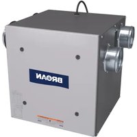
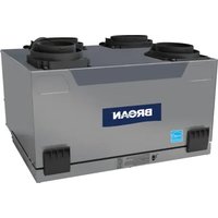
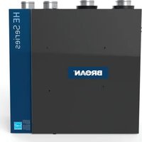
This balanced ventilation unit is designed to provide fresh air to your home while exhausting stale, humid air. Thanks to its energy/heat recovery module, the unit recovers a large proportion of heat or energy that is part of indoor or outdoor air according to the seasons to improve comfort and energy efficiency during the heating and the cooling periods. With the Virtuo Air Technology™, this unit responds to the variations in its environment in an autonomous way, ensuring to provide a proper level of ventilation and air quality. This unit also features automatic modes (AUTO or SMART) that manage autonomously the required ventilation level as per indoor and/or outdoor conditions. In colder areas, the unit will perform, at intervals, recovery module discreet defrost to maintain performance and comfort.
6.2 INTEGRATED CONTROL
All units are equipped with an integrated control, located in front of the electrical compartment. For more convenience, these units can be controlled using an optional wall control or the central forced-air system thermostat equipped with external fan activation.
MODE SELECTION
- To change the mode, use (+/-) to access the Mode screen. Press OK to edit the mode and use (+/-) to change the mode (Standby, Min, Max).
- Press OK to confirm selection. The airflows will be displayed for both MIN and MAX modes.
NOTE: If an optional auxiliary wall control or the central forced-air system thermostat equipped with external fan activation is used, it overrides the integrated control.

6.3 AHU MODE DISPLAY
Depending on unit configuration and/or installation, the unit could not be able to reach desired set minimum CFM. This situation could happen with installed configurations T-2 to T-5 due to AHU static pressure and a set minimum CFM below 75. In such a case, AHUXX (XX referring to desired minimum CFM value) will display on LCD screen. In AHU mode, the unit operates in intermittent mode to reach desired minimum CFM value. Intermittent mode duration varies as per desired minimum CFM value.
7. SERVICE PARTS

VL0091
| ITEM | DESCRIPTION | PART NUMBER | B180H75RT | B180E75RT | B230H75RS | B230H75RT | B210E75RS | B210E75RT |
| 1 6" | port warm side SV66139 2 2 2 2 2 2 | |||||||
| 2 6" | metal port motorized damper SV66135 1 1 1 1 1 1 | |||||||
| 3 Electronic assembly (180 models) SV68027** 1 1 | ||||||||
| 4 Electronic assembly with cooling fan kit (210-230 models) SV68028** 1 1 1 1 | ||||||||
| 5 Cooling fan kit for electronic (210-230 models) SV68031 | 1 1 1 1 | |||||||
| 6 Terminal blocks | SV66145 1 1 1 1 1 1 | |||||||
| 7 6" | exhaust port assembly | SV66137 1 1 1 1 1 1 | ||||||
| 8 Door latches and keepers for door | SV61218 1 1 1 1 1 1 | |||||||
| 9 Thermistor | SV66134 1 1 1 1 1 1 | |||||||
| 10 Recirculation damper with thermistor | SV68029 1 1 1 1 1 1 | |||||||
| 11 Exhaust blower assembly with damper (180 models) | SV68022 1 1 | |||||||
| 12 Exhaust blower assembly with damper (210-230 models) | SV68024 | 1 | 1 | 1 | 1 | |||
| 13 Supply blower assembly (180 models) | SV68021 1 1 | |||||||
| 14 Supply blower assembly (210-230 models) | SV68023 | 1 1 | 1 | |||||
| 15 Core ERV 75 % | SV68018 | 1 | 1 | 1 | ||||
| 16 Core HRV 75 % | SV68019 1 | 1 1 | ||||||
| 17 Core sliders kit with screws | SV68026 1 1 1 1 1 1 | |||||||
| 18 M ERV8 filters kit | SV68020 1 1 1 1 1 1 | |||||||
| 19 Door | SV68030 1 1 1 1 1 1 | |||||||
| 20 Exhaust damper | SV68025 1 1 1 1 1 1 | |||||||
| * Hardware kit | SV66146 1 1 1 1 1 1 | |||||||
| * Fuse for PCB | SV66147 1 1 1 1 1 1 | |||||||
| * 1/2" hose | SV00592 1 | 1 1 |
* Not shown.
** See next page to get the part number that corresponds to the ventilation unit model.
| VENTILATION UNIT MODEL | ||||||
| ELECTRONIC ASSEMBLY PART NUMBER | B180H75RT | B180E75RT | B230H75RS | B230H75RT | B210E75RS | B210E75RT |
| SV68027-01 | X | |||||
| SV68027-02 | X | |||||
| SV68028-01 | X | |||||
| SV68028-02 | X | |||||
| SV68028-03 | X | |||||
| SV68028-04 | X | |||||
REPLACEMENT PARTS AND REPAIRS
In order to ensure your ventilation unit remains in good working condition, you must use the manufacturer's genuine replacement parts only. The manufacturer's genuine replacement parts are specially designed for each unit and are manufactured to comply with all the applicable certification standards and maintain a high standard of safety. Any third party replacement part used may cause serious damage and drastically reduce the performance level of your unit, which will result in premature failing. The manufacturer recommends to contact a certified service depot for all replacement parts and repairs.
8. INSTALLER'S TROUBLESHOOTING
WARNING
The wearing of safety glasses and gloves is recommended since a few diagnosis procedures may require the unit to be in operation while proceeding. Be careful with moving and live parts to prevent any risk of injury.
| ERROR | DESCRIPTION SOLUTION | |
| E01 | Supply damper range | STEP 1: Unplug the unit, inspect the damper system, remove any undesirable obstacle or dirt (filters and core may have to be removed to access the damper system). Plug the unit. |
| E02 Supply damper timeout | ||
| E03 Supply damper | ||
| E05 | Exhaust damper range | STEP 1: Unplug the unit, inspect the damper system, remove any undesirable obstacle or dirt (filters and core may have to be removed to access the damper system). Plug the unit. |
| E06 Exhaust damper timeout | ||
| E07 Exhaust damper | ||
| E09 | Recirculation damper range | STEP 1: Unplug the unit, inspect the damper system, remove any undesirable obstacle or dirt (filters and core may have to be removed to access the damper system). Plug the unit. |
| E10 Recirculation damper timeout | ||
| E11 Recirculation damper | ||
| E22 Supply airflow STEP 1: Unplug the unit. Perform a visual inspection of the supply damper system. Clean filters, distribution registers and outside supply hood. Inspect ducting to ensure it is not squeezed or bent. Plug the unit. If STEP 1 did not fix the problem, perform STEP 2: Remove ducting of the supply path. On the LCD screen, select MAX to check if the unit is able to reach the selected flow. If so, review the ducting path. If STEP 2 did not fix the problem, perform STEP 3: On the LCD screen, select the MIN and MAX flow setting values then reset the unit. MAX flow value will display on the LCD screen. If MAX flow is above desired MAX flow, set MAX and MIN flows. If STEP 3 did not fix the problem, perform STEP 4: Replace the supply blower and repeat STEP 3. If STEP 4 did not fix the problem, perform STEP 5: Replace the electronic assembly. See also section 8.1. | ||
| E23 Supply motor (drive over current) STEP 1: Unplug/plug the unit. | ||
| E27 Supply motor (drive foc duration) | ||
| E28 Supply motor (drive speed feedback) | ||
| E29 Supply motor (startup) | ||
| E24 Supply motor (drive over voltage) | STEP 1: Unplug/plug the unit. Under and over voltage may be detected with severe in-house power supply fluctuation and stop the motor for protection. If STEP 1 did not fix the problem, perform STEP 2: Replace the electronic assembly. | |
| E25 Supply motor (drive under voltage) | ||
- INSTALLER'S TROUBLESHOOTING (CONT'D)
| ERROR | DESCRIPTION SOLUTION | |
| E26 | Supply motor (drive over temp) | STEP 1: Validate if the air exchanger is exposed to ambient temperatures within the operating limits (see p. 4)If STEP 1 did not fix the problem, perform STEP 2: Replace the electronic assembly. |
| E32 Exhaust airflow STEP 1: Unplug the unit. Per | perform a visual inspection of the exhaust damper system. Clean filters, distribution registers and outside exhaust hood. Make sure no non-return damper is installed in exhaust hood since it can freeze in winter. Inspect ducting to ensure it is not squeezed or bent. Plug the unit.If STEP 1 did not fix the problem, perform STEP 2: Remove ducting of the supply path. On the LCD screen, select MAX to check if the unit is able to reach the selected flow. If so, review the ducting path.If STEP 2 did not fix the problem, perform STEP 3: On the LCD screen, select the MIN and MAX flow setting values then reset the unit. MAX flow value will display on the LCD screen. If MAX flow is above desired MAX flow, set MAX and MIN flows.If STEP 3 did not fix the problem, perform STEP 4: Replace the exhaust blower and repeat STEP 3.If STEP 4 did not fix the problem, perform STEP 5: Replace the electronic assembly. See also section 8.1. | |
| E33 | Exhaust motor (drive over current) STEP | STEP 1: Unplug/plug the unit.If STEP 1 did not fix the problem, perform STEP 2: Remove core and clear the ventilation wheel from any dirt or obstacles.If STEP 2 did not fix the problem, perform STEP 3: Disconnect J3 (red) and connect a spare blower system. If it works, replace exhaust blower.If STEP 3 did not fix the problem, perform STEP 4: Replace the electronic assembly. |
| E37 Exhaust motor (drive foc duration) | ||
| E38 Exhaust motor (drive speed feedback) | ||
| E39 Exhaust motor (startup) | ||
| E34 | Exhaust motor (drive over voltage) | STEP 1: Unplug/plug the unit. Under and over voltage may be detected with severe in-house power supply fluctuation and stop the motor for protection.If STEP 1 did not fix the problem, perform STEP 2: Replace the electronic assembly. |
| E35 Exhaust motor (drive under voltage) | ||
| E36 | Exhaust motor (drive over temp) | STEP 1: Validate if the air exchanger is exposed to ambient temperatures within the operating limits (see p. 4)If STEP 1 did not fix the problem, perform STEP 2: Replace the electronic assembly. |
| E40 Outside air thermistor STEP 1: Check if ther | rmistor is well connected in connector J7A.If STEP 1 did not fix the problem, perform STEP 2: Disconnect connector J7A and check if the measured resistance (thermistor connector) is within 5 Kohms to 120 Kohms. If outside the range, replace the thermistor.If STEP 2 did not fix the problem, perform STEP 3: Replace the electronic assembly. | |
| E41 | Distribution air thermistor | STEP 1: Check if thermistor is well connected in connector J7B.If STEP 1 did not fix the problem, perform STEP 2: Disconnect connector J7B and check if the measured resistance (thermistor connector) is within 5 Kohms to 120 Kohms. If outside the range, replace the thermistor.If STEP 2 did not fix the problem, perform STEP 3: Replace the electronic assembly. |
| E42 PCBA thermistor fault STEP 1: Replace the | electronic assembly. | |
| E43 | PCBA temperature over limit | STEP 1: Validate if the air exchanger is exposed to ambient temperatures within the operating limits (see p. 4)If STEP 1 did not fix the problem, perform STEP 2: Replace the electronic assembly. |
| E50 Wall control communication lost STEP 1: Unplug unit, inspect wires, plug unit.If STEP 1 did not fix the problem, perform STEP 2: Remove wall control from the wall installation and test with a short cable. If it works, bring a new cable to the wall installation location.If STEP 2 did not fix the problem, perform STEP 3: Test the air exchanger with a spare wall control. If it works, replace the wall control.If STEP 3 did not fix the problem, perform STEP 4: Replace the electronic assembly. | ||
| E51 | Wall control sensor | STEP 1: Unplug unit, inspect wires, plug unit.If STEP 1 did not fix the problem, perform STEP 2: Replace the wall control. |
| E60 | Protection mode | STEP 1: Perform general inspection of the unit (dampers, core, filters). |
8. INSTALLER'S TROUBLESHOOTING (CONT'D)
| WARNING DESCRIPTION SOLUTION | |
| W22 | Supply airflowSTEP 1: Unplug the unit. Perform a visual inspection of the supply damper system. Clean filters, distribution registers and outside supply hood. Inspect ducting to ensure it is not squeezed or bent. Plug the unit.If STEP 1 did not fix the problem, perform STEP 2: Remove ducting of the supply path. On the LCD screen, select MAX to check if the unit is able to reach the selected flow. If so, review the ducting path.If STEP 2 did not fix the problem, perform STEP 3: On the LCD screen, select the MIN and MAX flow setting values then reset the unit. MAX flow value will display on the LCD screen. If MAX flow is above desired MAX flow, set MAX and MIN flows.If STEP 3 did not fix the problem, perform STEP 4: Replace the supply blower and repeat STEP 3.If STEP 4 did not fix the problem, perform STEP 5: Replace the electronic assembly. |
| W32 | Exhaust airflowSTEP 1: Unplug the unit. Perform a visual inspection of the exhaust damper system. Clean filters, distribution registers and outside exhaust hood. Make sure no non-return damper is installed in exhaust hood since it can freeze in winter. Inspect ducting to ensure it is not squeezed or bent.Plug the unit.If STEP 1 did not fix the problem, perform STEP 2: Remove ducting of the supply path. On the LCD screen, select MAX to check if the unit is able to reach the selected flow. If so, review the ducting path.If STEP 2 did not fix the problem, perform STEP 3: On the LCD screen, select the MIN and MAX flow setting values then reset the unit. MAX flow value will display on the LCD screen. If MAX flowis above desired MAX flow, set MAX and MIN flows.If STEP 3 did not fix the problem, perform STEP 4: Replace the exhaust blower and repeat STEP 3.If STEP 4 did not fix the problem, perform STEP 5: Replace the electronic assembly. |
| W52 Initial setting incomplete | STEP 1: Press + or - to access the selection menu.STEP 2: Complete configuration. (Refer to section 5 for more details). |
| W61 Protection mode electronics overheating | The unit is currently in protection mode. The power transmitted to the motor is deliberately reduced to decrease electronics temperature. The unit will exit this mode by itself once conditions are back to normal. It is normal to observe reduction in airflows during this period. This condition should appear only when the unit is set in high speed and located in a warmer environment, for example over 30°C ( 86°F ). |
CAUTION
Make sure that no piece of mineral wool will enter in the unit during installation. Otherwise, this could reduce airflow and generate vibrations and noise in the unit.
NOTE: 210 and 230 CFM models have a cooling fan in electrical box that can start if ambient temperature near the unit is over 104° F.
8.1 ELECTRONIC PROTECTION TO PREVENT ABNORMAL HIGH STATIC PRESSURE
180 CFM ERV Models
The unit will reduce airflow by 30 CFM if the max airflow during auto-balancing procedure is 130 CFM or less to prevent ERV core membrane deformation due to very high static pressure (over 1.3 in. w.g.).
All 180 CFM Models
Error E22 or E32 will display if the maximum airflow is 90 CFM or less during the auto-balancing procedure (the unit will attempt to execute auto-balancing procedure 3 times before displaying an error). Static pressure of ducting shall be reduced to allow good operation of the unit.
210 CFM ERV Models
The unit will reduce airflow by 30 CFM if the max airflow during auto-balancing procedure is 160 CFM or less to prevent ERV core membrane deformation due to very high static pressure (over 1.3 in. w.g.).
All 210 and 230 CFM Models
Error E22 or E32 will display if the maximum airflow is 120 CFM or less during the auto-balancing procedure (the unit will attempt to execute auto-balancing procedure 3 times before displaying an error). Static pressure of ducting shall be reduced to allow good operation of the unit.
9. MAINTENANCE
WARNING
High voltage risk. During maintenance or repairs, always stop the unit then unplug it to prevent any risk of electric shock. The wearing of safety glasses and gloves is recommended when handling unit components to prevent any risk of injury that could be caused by the presence of thin metal.
9.1 QUARTERLY
- Disconnect power cord.
- The door of this unit is hinged and maintained closed by 2 latches. Open them and set aside.
- Clean the inside of the door with a damp cloth.
- Clean filters:
- Remove filters.
• Vacuum to remove most of the dust. - Wash with a mixture of warm water and mild soap. You may add bleach if you wish to disinfect (one tablespoon per gallon). Rinse thoroughly. Shake filters to remove excess water and let dry.
Note: The optional filter is a disposable filter. It should be replaced when it is too dirty.
-
Remove the core.
-
Clean the condensing tray with a damp cloth.
-
Check the exterior air intake hood:
• Make sure there are no leaves, twigs, ice or snow that could be drawn into the vent.

CAUTION
A blocked air vent or filter, even partially, could cause the unit to malfunction. The comfort provided by the unit could be reduced and the risk of unit frost could increase. This could cause unit breakdown and/or damage to property.
- Clean if necessary.
- Rotate the blower wheels by hand. If one of the wheels does not rotate easily, contact your installer.
- Reassemble the components. Pay special attention to the filters by making sure that they are engaged in their slots.
- Close the unit door and reconnect power supply.
- Reset filters, if required. If using an optional main wall control (SPEED, DEHUMIDISTAT OR AUTOMATIC), press on the INT/AUTO button for 5 seconds to reset the filters. If using the ADVANCED optional main wall control, follow the instructions on the touch screen.

OPTIONAL FILTER (EXHAUST FILTER NOT INCLUDED)
Pull the core 3" to 4" out.
Bend the two filter frame flaps to form a 45-degree angle, as illustrated below.

Install the filter over the core as illustrated hereafter.
Push the core and the filter to the bottom of the unit.

NOTE: The optional filter replaces the MERV8 filter.
9. MAINTENANCE (CONT'D)
9.2 ANNUAL (AT FALL)
- Repeat steps 1 to 6 from the previous section and continue with the following steps:
CAUTION
- Handle the recovery core with care.
- Clean the recovery core:

| HRV MODELS ERV MODELS | |
| Remove the core.Let it soak in a mixture of cold or lukewarm water and mild soap (dishwashing liquid).Rinse thoroughly.Shake the core to remove excess water and let it dry. | Remove the dust on the core using a vacuum cleaner and a soft brush attachment.CAUTION: DO NOT SOAK THE ENERGY RECOVERY CORE IN WATER |
- Clean the blower assemblies. Do not disassemble the blower assemblies.
- Remove the dust using a vacuum cleaner with a soft brush attachment.
- Reassemble the components.
- Reconnect power supply.
10. USER'S TROUBLESHOOTING
If the unit does not work properly, reset the unit by unplugging it for one minute, then replug it.
Contact customer service at 1-800-558-1711 for any unresolved issue.
| PROBLEM TRY THIS | |
| 1. Nothing works. • See if the unit is plugged in.• See if the unit is receiving power from the house circuit breaker or fuse. | |
| 2. Noisy unit. | • Clean the unit (see section 9). If the problem is not solved, contact your installer. |
| 3. Condensation inside windows under cold weather conditions. | • Operate the unit at MAX speed during activities generating excess humidity (family gatherings, extra cooking, etc.).• Leave curtains half-open to allow air circulation.• Store all firewood in a closed room with a dehumidifier or in a well ventilated room, or store the wood outdoors.• Keep the temperature in your house above 64°F. |
| 4. Humidity inside under hot/humid weather conditions. | • Operate the unit in MIN speed.• Temporarily switch to INT mode (if available).• Use a dehumidifier. |
| 5. Air too dry. • Operate the unit at MIN speed. | • Temporarily switch to INT mode (if available).• Temporarily use a humidifier. |
| 6. Air too cold at the air supply register. • Make sure the outdoor hoods are not blocked.• Operate the unit at MIN speed.• Install a duct heater (contact your installer). | |
11. WARRANTY
This ventilation unit is a high quality product, built and packaged with care. The manufacturer warrants to the original purchaser of its product, that such products will be free from defects for the period stated below, from date of original purchase. For all units, the warranty covers parts only against any operational defect. This 5-year warranty is subject to performance of the core maintenance according to recommendations in this manual. The heat recovery core (HRV) has a 10-year warranty, and the energy recovery core (ERV) has a 5-year warranty. If any defect should occur, we urge you to read the user guide carefully. If the problem persists, observe the following rules:
RULES TO FOLLOW
If the unit is defective, contact your ventilation contractor (see address on your manual's cover page). The contractor will determine with you the reason for the defect, and if needed, do the replacement or repair. If ever it is impossible to reach your ventilation contractor, call 1-800-558-1711 (in North America); the personnel will be pleased to give you the phone number of a distributor or a service center near you.
REPLACEMENT PARTS AND REPAIR
In order to ensure your ventilation unit remains in good working condition, you must use the Broan genuine replacement parts only. The Broan genuine replacement parts are specially designed for each unit and are manufactured to comply with all the applicable certification standards and maintain a high standard of safety. Any third party replacement part used may cause serious damage and drastically reduce the performance level of your unit, which will result in premature failing. Broan also recommends that you contact a service depot certified by the manufacturer for all replacement parts and repair.
BILL OF PURCHASE
No replacement or repair covered by the warranty will be carried out unless the unit is accompanied by a copy of the original bill of purchase. Please retain your original.
MISCELLANEOUS COSTS
In each case, the labor and shipping costs for the removal of a defective part and/or installation of a compliant part will not be covered by the manufacturer.
CONDITIONS AND LIMITATIONS
These units are created for residential use only and must be used in a building as defined below:
Building: All structures zoned and/or erected for the act, process or art of human or animal habitation and/or the storage or warehousing of goods.
Residential use: Dwelling, lodging, suite: Building, or part of a building, intended to act as either the domicile to one or several people which can include general sanitary, food consumption and rest facilities. Buildings of only one room or a group of rooms including those occupied by a tenant or owner; comprise the lodgings, the individual rooms of the motels, hotels, rooming/lodging houses, boarding/half-way/foster homes, dormitories, and suites, as well as the stores and the business establishments constituted by only one room in a dwelling.
Commercial use: Agricultural establishment, commercial establishment for assembly, care, or detention: Building or part of a building that does not contain a dwelling, situated on land dedicated to agriculture or farming and used primarily to shelter animals, or for the production, the storage or the treatment of agricultural or horticultural products or animal food. Building or part of a building, used for the display or retail of goods, professional or personal services, or commodities. Building, or part of a building used by persons gathering for civic activities, religious or political assembly, tourism, educational/vocational training, recreation or the consumption of food or drink. Building, or part of a building used to shelter persons of impaired physical or psychological states, persons requiring palliative care or medical treatments, or persons for reasons out of their control, cannot escape harm or threat of danger autonomously.
Industrial use: Building, or part of a building, used for the assembly, the manufacture, the creation, the treatment, the repair or the storage of products and combustible materials and that contain fuels that when ignited or exploded in sufficient quantity may constitute a risk of fire.
The above warranty applies to all cases where the damage is not a result of poor installation, improper use, mistreatment or negligence, acts of God, or any other circumstances beyond the control of the manufacturer. Furthermore, the manufacturer will not be held responsible for any bodily injury or damage to personal property or real estate, whether caused directly or indirectly by the unit. This warranty supersedes all prior warranties.
Broan-NuTone LLC, 926 West State Street, Hartford, Wisconsin, USA 53027 Broan-NuTone.com 800-558-1711
BROAN®
| B180H75RT | |
| B180E75RT | |
| B230H75RT B230 | H75RS |
| B210E75RT B210 | E75RS |

REGISTRE SU PRODUCTO EN LÍNEA EN:
Broan-NuTone.com/en-us/home/customer-service/product-registration
O

3. CONEXIONES (CONT.)
3.2 CONEXIÓN ELÉCTRICA CON EL CONTROL MURAL AUXILIAR OPCIONAL
3.2.1 CONEXIÓN ELECTRICA CON EL CONTROL MURAL AUXILIAR OPCIONAL 20-40-60

VC0243
VL0091
REPLACEMENT PARTS AND REPAIR
Broan-NuTone LLC, 926 West State Street, Hartford, Wisconsin, USA 53027
Broan-NuTone.com
800-558-1711
- INSTALLER: READ THESE INSTRUCTIONS SAVE THEM FOR USER
- WARNING
- CAUTION
- LIMITATION
- ⚠ WARNING
- TABLE OF CONTENTS
- TECHNICAL DATA
- INSTALLATION
- CONNECTIONS
- WIRING DIAGRAM
- NAVIGATION ON LCD SCREEN
- USING THIS UNIT
- SERVICE PARTS
- INSTALLER'S TROUBLESHOOTING
- MAINTENANCE
- USER'S TROUBLESHOOTING
- WARRANTY
- CONSUMER INFORMATION
- AIR DISTRIBUTION (NORMAL OPERATION)
- LOCATING AND MOUNTING THE UNIT
- LOCATING AND MOUNTING THE UNIT (CONT.)
- SUSPENDED TO THE JOISTS OR TRUSTS
- OR
- WALL MOUNTED
- INSTALLING THE DUCTWORK AND THE REGISTERS
- FULLY DUCTED SYSTEM (T-1) (THIS CONFIGURATION ALLOWS RECIRCULATION MODE TO OPERATE.)
- STALE AIR FROM BUILDING
- FRESH AIR TO BUILDING
- EXHAUST DUCTED SYSTEM (T-2) (THIS CONFIGURATION ALLOWS RECIRCULATION MODE TO OPERATE.)
- SIMPLIFIED INSTALLATION (T-4) (THIS CONFIGURATION DOES NOT ALLOW RECIRCULATION MODE TO OPERATE.)
- NOTE: FOR THIS TYPE OF CONFIGURATION, THE T-4 OPTION MUST BE SELECTED ON THE LCD SCREEN WHEN AUTO-BALANCING THE UNIT (SEE SECTION 5.2)
- CONNECTING THE DRAIN (HRV ONLY)
- EXTERIOR HOODS INSTALLATION / LOCATION
- CONNECTING THE DUCTS TO THE UNIT
- INSULATED FLEXIBLE DUCTS
- DUCTS CONNECTION
- ELECTRICAL CONNECTION TO OPTIONAL MAIN WALL CONTROL
- ELECTRICAL CONNECTION TO SPEED, DEHUMIDISTAT OR AUTOMATIC OPTIONAL MAIN WALL CONTROL
- ELECTRICAL CONNECTION TO ADVANCED OPTIONAL MAIN WALL CONTROL
- ELECTRICAL CONNECTION TO OPTIONAL AUXILIARY WALL CONTROL
- ELECTRICAL CONNECTION TO 20-40-60 OPTIONAL AUXILIARY WALL CONTROL
- ELECTRICAL CONNECTION TO DRY CONTACT OPTIONAL AUXILIARY WALL CONTROL (E.G. CRANK TIMER)
- CONNECTION TO THE CENTRAL FORCED-AIR SYSTEM
- UNIT OPERATION USING A DRY CONTACT CONNECTION
- UNIT INTERCONNECTION WITH CENTRAL FORCED-AIR SYSTEM (R/C/G/GF)
- SYNCHRONIZATION WITH CENTRAL FORCED-AIR SYSTEM FUNCTION
- PRESS ON OK BUTTON TO
- UNIT FIRST BOOT
- PREPARATION
- AUTO-BALANCING PROCEDURE
- INSTALLATION CONFIGURATION SELECTION
- SETTINGS MODIFICATION
- FACTORY SETTINGS RESET
- YOUR VENTILATION SYSTEM
- INTEGRATED CONTROL
- MODE SELECTION
- AHU MODE DISPLAY
- INSTALLER'S TROUBLESHOOTING (CONT'D)
- ELECTRONIC PROTECTION TO PREVENT ABNORMAL HIGH STATIC PRESSURE
- CFM ERV MODELS
- ALL 180 CFM MODELS
- ALL 210 AND 230 CFM MODELS
- QUARTERLY
- MAINTENANCE (CONT'D)
- ANNUAL (AT FALL)
- RULES TO FOLLOW
- REPLACEMENT PARTS AND REPAIR
- BILL OF PURCHASE
- MISCELLANEOUS COSTS
- CONDITIONS AND LIMITATIONS
- BROAN®
- O
- CONEXIONES (CONT.)
- CONEXIÓN ELÉCTRICA CON EL CONTROL MURAL AUXILIAR OPCIONAL
- CONEXIÓN ELECTRICA CON EL CONTROL MURAL AUXILIAR OPCIONAL
Brand : BROAN
Model : B230H75RT
Category : Air conditioner