
ELPMBUNI - Projector EPSON - Free user manual and instructions
Find the device manual for free ELPMBUNI EPSON in PDF.
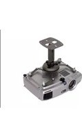


| Product Type | Replacement lamp module for video projectors |
| Brand | Epson |
| Model | ELPMBUNI |
| Compatibility | Designed for select Epson EB-series multimedia projectors |
| Lamp Technology | UHE (Ultra High Efficiency) lamp |
| Rated Power Consumption | 200 W (typical) |
| Lamp Life (Standard Mode) | Up to 5000 hours |
| Lamp Life (ECO Mode) | Up to 10000 hours |
| Brightness Output | Optimized for the original projector's lumen rating |
| Color Temperature | Standard projector color balance |
| Operating Temperature | 5 °C to 35 °C |
| Storage Temperature | -10 °C to 60 °C |
| Dimensions (W x D x H) | Approx. 150 x 100 x 80 mm |
| Weight | Approx. 280 g |
| Connector Type | Proprietary locking connector compatible with Epson mounts |
| Installation | Tool-free lamp cover removal for quick replacement |
| Maintenance | Regular air filter cleaning recommended to maintain cooling |
| Cleaning Instructions | Use a soft, dry cloth; avoid direct contact with the lamp glass |
| Safety Features | Integrated thermal protection and UV shielding |
| Environmental Compliance | RoHS compliant |
| Package Contents | Lamp module, installation guide, protective packaging |
| Warranty | Standard Epson limited warranty (varies by region) |
Frequently Asked Questions - ELPMBUNI EPSON
User questions about ELPMBUNI EPSON
0 question about this device. Answer the ones you know or ask your own.
Ask a new question about this device
Download the instructions for your Projector in PDF format for free! Find your manual ELPMBUNI - EPSON and take your electronic device back in hand. On this page are published all the documents necessary for the use of your device. ELPMBUNI by EPSON.
USER MANUAL ELPMBUNI EPSON
ELPMBUNI
EPSON AMERICA, INC.
INDIANAPOLIS DISTRIBUTION CENTER
2350 Stafford Road Suite 101
Plainfield, IN 46168
EPSON
Table of Contents
Warranty ....- 3 -
Contact Premier Mounts - 3 -
Warning Statements.... - 4 -
Parts List.... - 5 -
Installation Tools .... - 5 -
ELPMBUNI Universal Mount Assembly - 6 -
Projector Preparation .... - 7 -
Securing the Bracket to the Projector ....- 9 -
Leveling the Mounting bracket....-14-
Securing the Upper Assembly Ceiling Plate....- 15 -
Low-Profile Installation.... - 16 -
Securing the Projector to the Upper Assembly....- 18 -
Final Adjustments.... - 19 -
Installing the Plastic Caps....- 20 -
Warranty
Limited Lifetime Warranty
All Premier Mounts products carry a limited lifetime warranty from ship date against defects in materials and workmanship. Premier Mounts is not liable for improper installation that results in damage to mounts, adapters, display equipment or personal injury.
DISCLAIMER OF WARRANTY
THE FOREGOING WARRANTY IS IN LIEU OF ALL OTHER WARRANTIES, EXPRESS OR IMPLIED, INCLUDING BUT NOT LIMITED TO THE IMPLIED WARRANTIES OF MERCHANTABILITY AND FITNESS FOR A PARTICULAR PURPOSE.
Contact Premier Mounts
In the event of missing and/or damage equipment, or technical questions, the following information can help in the completion of the installation.
Customer Service - (800) 368-9700
Technical Support – techsupport@mounts.com
Warning Statements
WARNING:
PREMIER MOUNTS DOES NOT WARRANT AGAINST DAMAGE CAUSED BY THE USE OF ANY PREMIER MOUNTS PRODUCT FOR PURPOSES OTHER THAN THOSE FOR WHICH IT WAS DESIGNED OR DAMAGE CAUSED BY UNAUTHORIZED ATTACHMENTS OR MODIFICATIONS, AND IS NOT RESPONSIBLE FOR ANY DAMAGES, CLAIMS, DEMANDS, SUITS, ACTIONS OR CAUSES OF ACTION OF WHATEVER KIND RESULTING FROM, ARISING OUT OF OR IN ANY MANNER RELATING TO ANY SUCH USE, ATTACHMENTS OR MODIFICATIONS.
WARNING:
THE CEILING STRUCTURE MUST BE CAPABLE OF SUPPORTING A MAX WEIGHT OF 25 LBS., THE WEIGHT OF THE PROJECTOR. IF NOT, THE CEILING MUST BE REINFORCED. PROPER INSTALLATION PROCEDURE BY QUALIFIED PERSONNEL AS OUTLINED IN THE INSTALLATIONS INSTRUCTIONS MUST BE ADHERED TO. FAILURE TO DO SO COULD RESULT IN SERIOUS PERSONAL INJURY.
WARNING:
SAFETY MEASURES MUST BE PRACTICED AT ALL TIMES DURING THE INSTALLATION OF THIS PRODUCT. USE PROPER SAFETY GEAR AND TOOLS FOR THE INSTALLATION PROCEDURE TO PREVENT PERSONAL INJURY.
WARNING:
PRIOR TO THE INSTALLATION OF THIS PRODUCT, THE INSTALLATION INSTRUCTIONS SHOULD BE READ AND COMPLETELY UNDERSTOOD. THE INSTALLATION INSTRUCTIONS MUST BE READ TO PREVENT PERSONAL INJURY AND PROPERTY DAMAGE. KEEP THESE INSTALLATION INSTRUCTIONS IN AN EASILY ACCESSIBLE LOCATION FOR FUTURE REFERENCE.

Indicates that the power plug is to be disconnected from the power outlet.

Contact Premier Mounts with any questions - (800) 368-9700.

Safety precautions must be taken at all times.

Warning and Caution statements.

A secure structure must support the weight, or load, of the projector. When mounting to a ceiling that contains wooden studs, dead center of the wooden stud must be confirmed prior to installation.

Do not install on a structure that is prone to vibration, movement or chance of impact. Failure to do so could result in damage to the projector and/or damage to the mounting surface.

Do not install near heater, fireplace, direct sunlight, air conditioning or any other source of direct heat energy. Failure to do so may result in damage to the projector and could increase the risk of fire.

At least two qualified people should perform the installation procedure. Injury and/or damage can result from dropping or mishandling the projector.

Recommended mounting surfaces: wooden studs, solid-flat concrete, and reinforced metal studs. If the mount is to be installed on any surface other than wooden studs, use suitable hardware (which is commercially available).
Parts List
NOTE: This mount is shipped with all proper installation hardware and components. Make sure that none of these parts are missing and/or damaged before beginning installation. If there are parts missing and/or damaged, please stop the installation and contact Premier Mounts (800-368-9700).
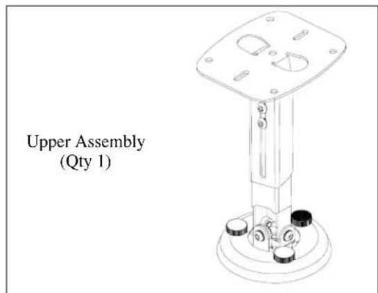
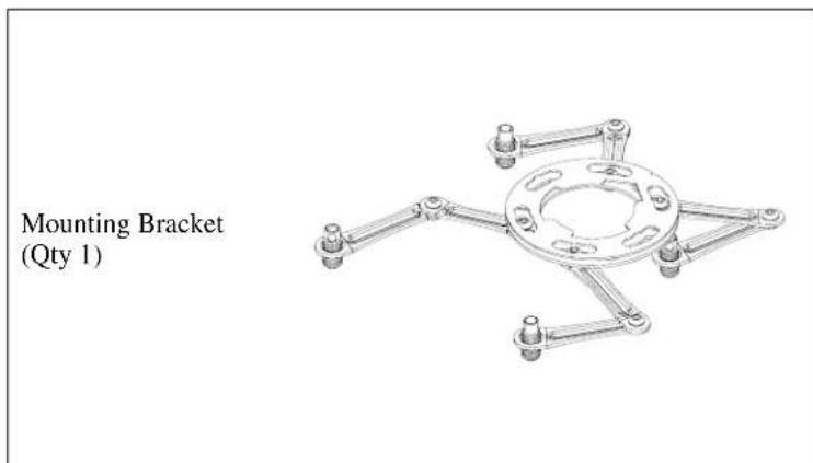
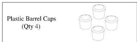
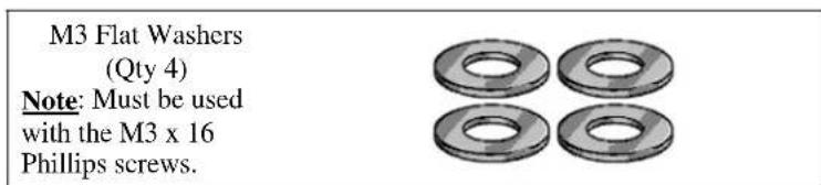
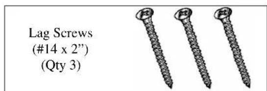
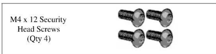
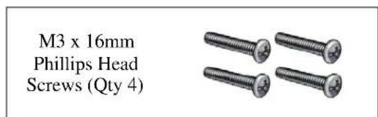
NOTE ____: The following hardware is included in the hardware pack but is not required for the installation.
M5 x 12mm Security Head Screws (Qty 4) M6 x 12mm Security Head Screws (Qty 4)
Installation Tools
Phillips Head Screw Driver Portable Drill
Soft Material/ Blanket Pencil
Allen Wrench (Supplied) Level (Supplied)
Tape Measure
Ladder
Stud Finder (Commercially Available)
M5 Allen Wrench
NOTE: Mounting screws will vary by projector. Please see the following pages for model specific hardware: Pages 10, 11, 12, and 13.
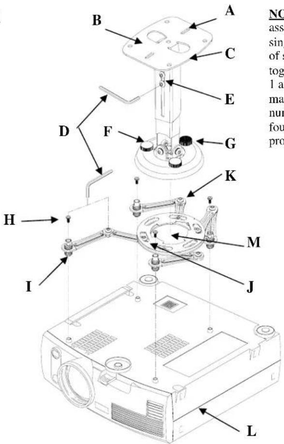
ELPMBUNI Universal Mount Assembly
A Single Wooden Stud Mounting Points B Solid Structure Mounting Points
C Ceiling Plate D Allen Wrench
E Height Adjustment Screws F Tension Knobs G Safety Knob H Security Screws I Leveling Barrels
J Universal Mounting Bracket K Leg Assembly L Projector (Not Supplied) M Tri-Lock Opening
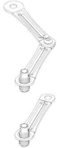
Combination Leg
Single Leg
Option 2
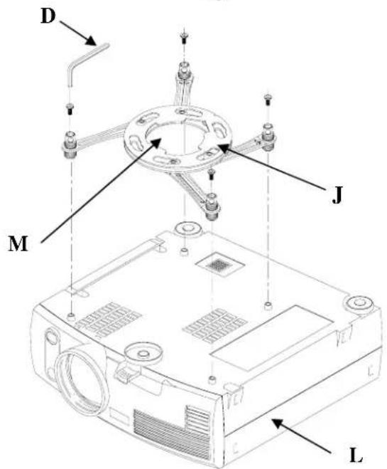
NOTE: The four (2-piece) leg assemblies can be used as single leg or any combination of single and dual legs together as shown in Options 1 and 2. The number of legs may vary depending on the number of mounting points found on the bottom of your projector.
NOTE: See the best configuration for your projector for filter and lamp access.
Projector Preparation
WARNING:
Proper installation procedure by qualified personnel as outlined in the installation instructions must be adhered to. Failure to do so could result in serious personal injury and possible damage to the projector.
CAUTION: THE PROJECTOR IS FRAGILE; HANDLE WITH CARE AT ALL TIMES.
NOTE:
Review the projectors manufacture's operation manual and refer to the ceiling installation instruction. Here you will normally find important reference information regarding installation dimensions such as (distance from the screen to the lens of the projector, top of the lens placement to the top screen etc. Adherence to these recommendations during your installation will enhance the quality of your final image on the screen.
- Carefully invert the projector and place it on a smooth flat surface.
- Identify the number of mounting points and screw thread (pitch) size.
- Most projectors have either three or four mounting points and are M4 in thread size (Figure 1).
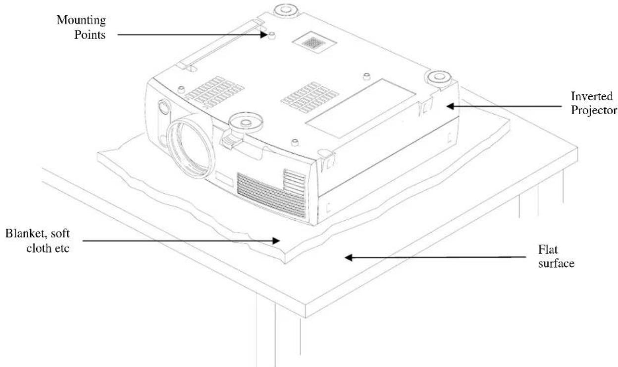
Figure 1
-
Separate the upper assembly from the projector mounting bracket by slightly loosening the two tension knurl knobs to create free play between the bracket tri-lock assembly and the upper section tri-lock assembly points.
-
Next loosen the safety screw knurl knob far enough to allow the two parts to be rotated 180° apart and separate.
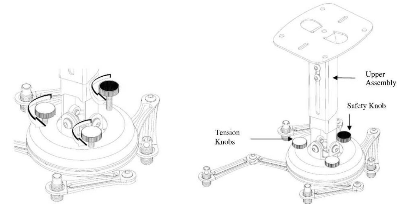
Figure 2 Figure 3
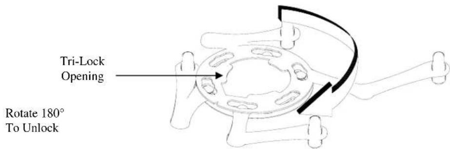
Figure 4
Securing the Bracket to the Projector
NOTE: The two-piece mounting legs are designed to allow routing of the legs around critical ventilation screens on the base of the projector as shown. You may also reduce the two-piece leg to a one-piece leg as shown for a better overall fit to the projector.
-
Locate the mounting points on the bottom of the projector and use the appropriate number of mounting legs.
-
Select the mounting hardware that your projector requires and loosely install the universal mount to your projector.
NOTE: If your projector requires M3 mounting hardware. Use the M3 x 16 Phillips screws with the M3 flat washers (supplied). Insert the M3 x 16 Phillips screws with the flat washers attached through the leveling barrel. Using a Phillips screwdriver, loosely secure the screws to the projector (Figure A).
NOTE: The levelers and leg assembly screws must be loose in order to adjust the height of the mounting bracket.
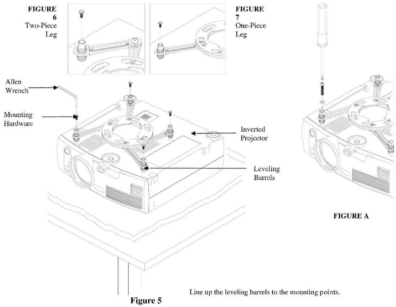
NOTE: If your projector model is not shown, when arranging the leg combination, simply ensure access to filters and lamp housings when aligning brackets. This mount works with all sub-25 pound projectors.
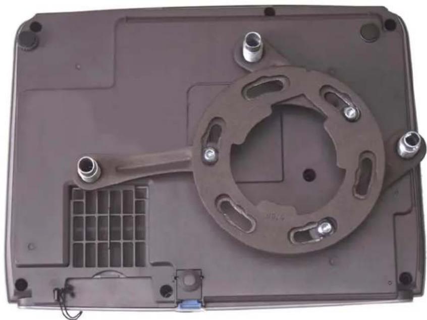
PowerLite S3, S4, 62C, 76C, 82C, Hardware: M4 x 12mm (Qty 3)
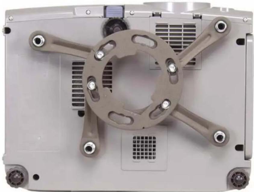
PowerLite 830p, 835p Hardware: M4 x 12mm (Qty 4)
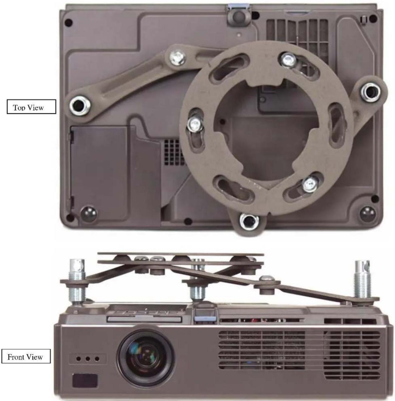
PowerLite 732c, 737c, 740C, 745C, 750c, 755c, 760c, 765c
Hardware: M4 x 12mm (Qty 3)
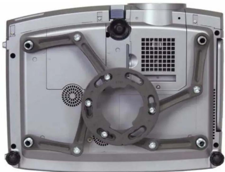
PowerLite 7800p, 7850p, 7900p
Hardware: M4 x 12mm (Qty 4)
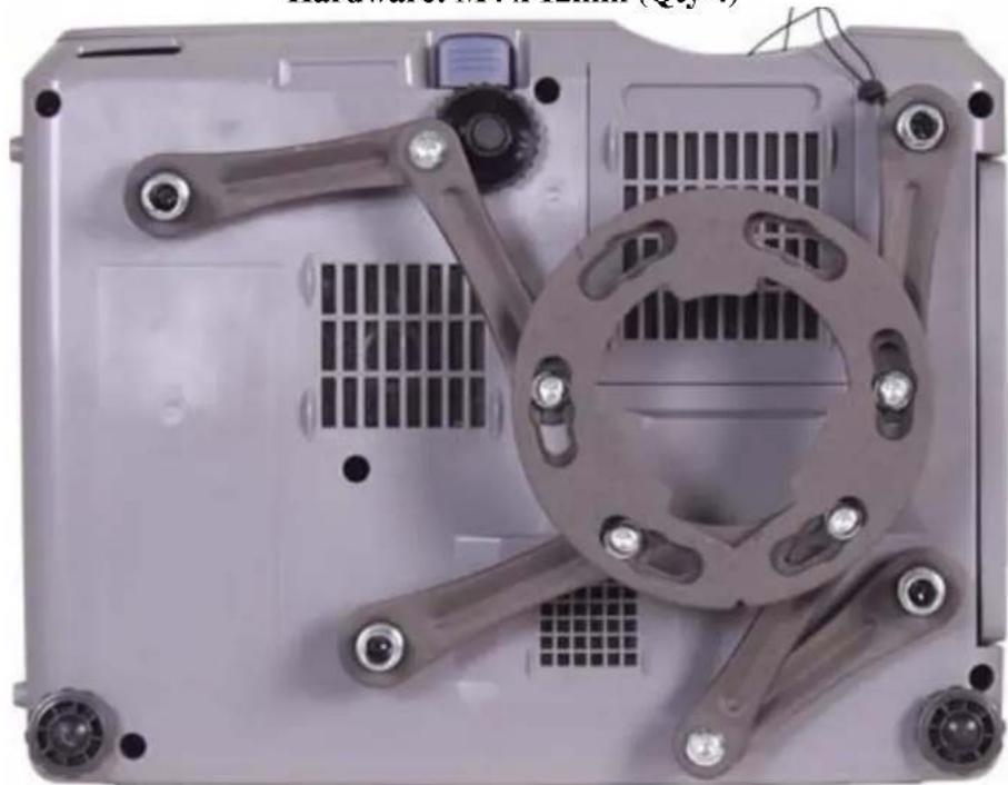
PowerLite 61p, 81p, 821p Hardware: M4 x 12mm (Qty 4)
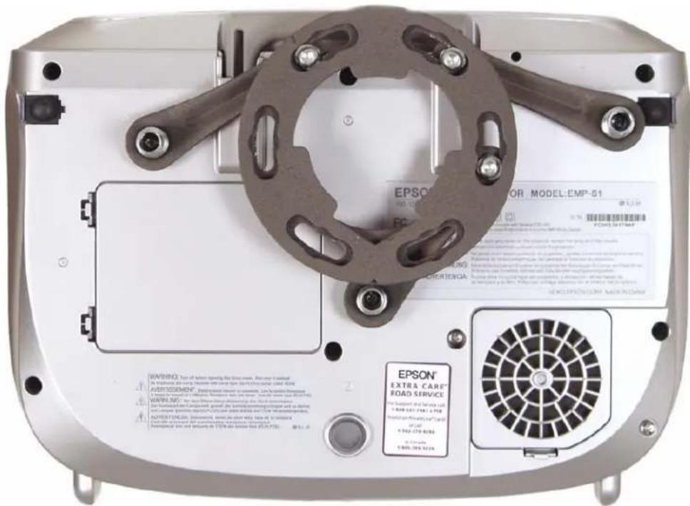
PowerLite S1, S1+ Hardware: M4 x 12mm (Qty 3)
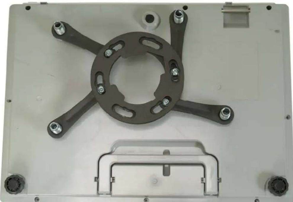
PowerLite 6100i Hardware: M4 x 12mm (Qty 4)
Leveling the Mounting bracket
- Rotate the leveling barrels to level the mounting bracket next, position the mounting bracket so that it avoids most, if not all, ventilation points (including lamp & filter access doors).
- When the position desired is achieved tighten the mounting hardware to the projector then tighten the hex head leg screws with the Allen wrench (supplied) (Figure 8 and Figure 9).
CAUTION: Secure but do not over-tighten the mounting hardware. Failure to do so will result in damaging the threads in the projector.
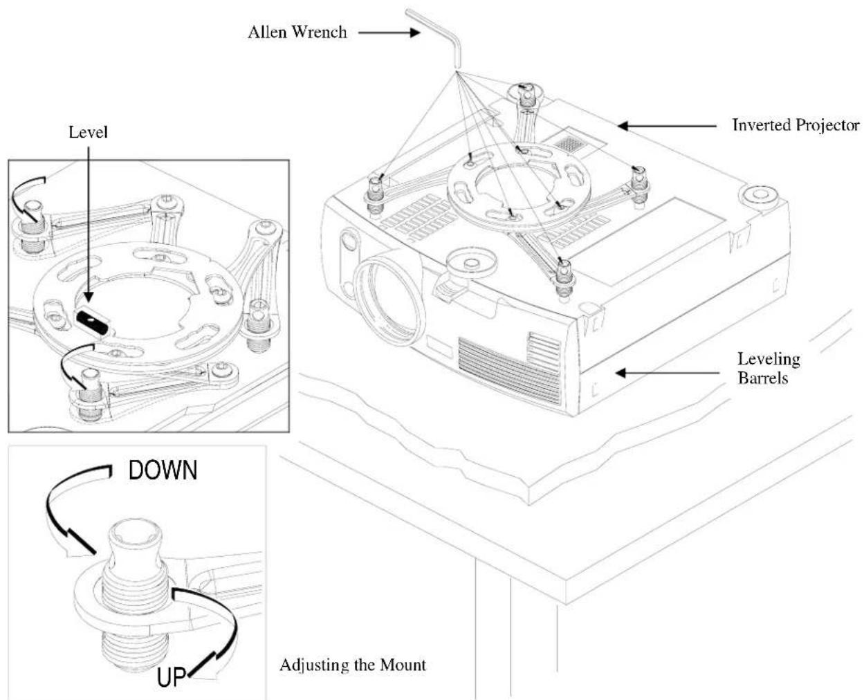
Figure 8
Securing the Upper Assembly Ceiling Plate
- Review your projector's distance calculation to determine what distance is recommended from the front of the lens to the edge of the screen for best picture ratio.
- Locate the inverted projectors top of the lens point to a point centered horizontally on the screen and no higher then the top image edge of the screen).
- It is normally better to have the top edge of the lens as close to parallel with the top image edge of the screen as well.
- Before you mount your screen and projector, make sure the mounting location will safely support the weight of the projector.
NOTE: Make sure to measure from the center of the mounting bracket to the front edge of the lens to determine the proper placement of the center of the upper assembly.
NOTE: If installing the security kit (ELPMBSEC), please refer to the security kit installation guide before attaching the ceiling plate to the ceiling or wall.
- Secure the ceiling assembly into a solid wood ceiling stud with the three (3) #14 x 2" wood screws (supplied) or with other (commercially available) hardware depending on your installation environment (Figure 9).
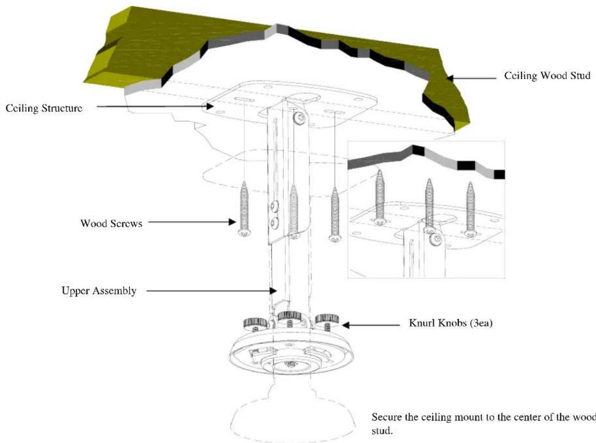
Figure 9
Low-Profile Installation
- If your installation requires the overall height of the mount to be less that the approximate 9" shown with the standard mount assembly, you can convert the height to only 2 ½" by simply removing the adjustment channel as shown.
- Once the extension channel is removed, attach the upper ceiling plate to the ceiling.
- Once attached install the bell housing assembly to the upper ceiling plate as shown (Figure 10, Figure 11, and Figure 12).
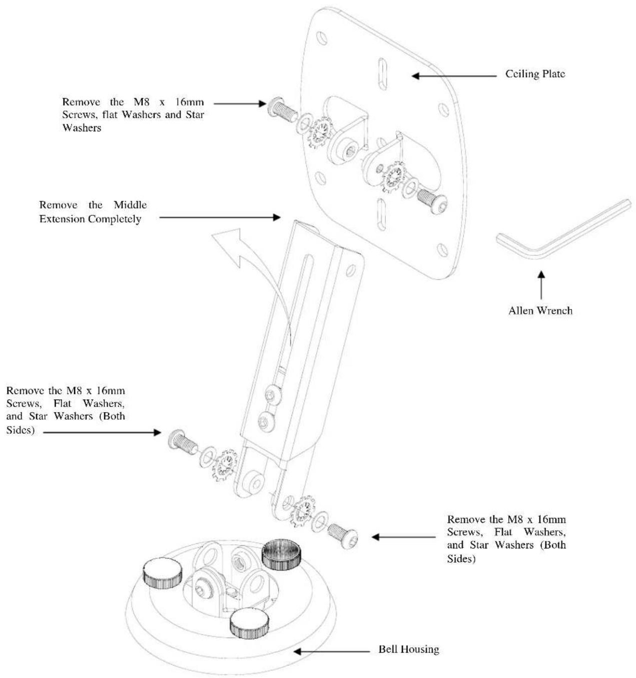
Figure 10
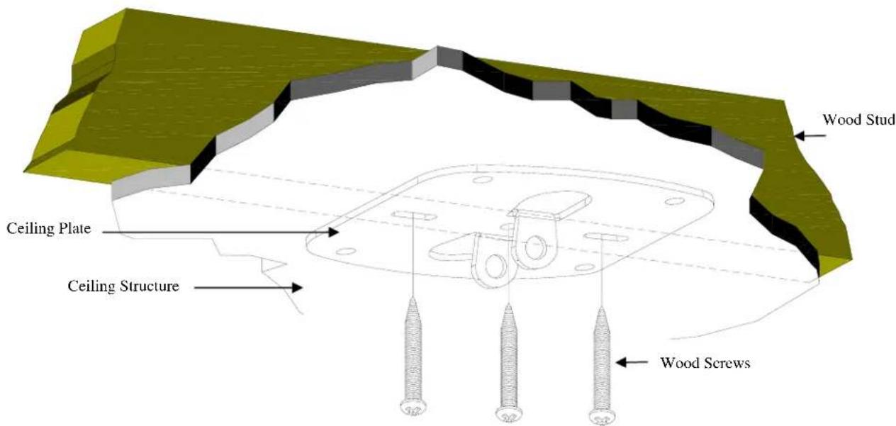
Figure 11
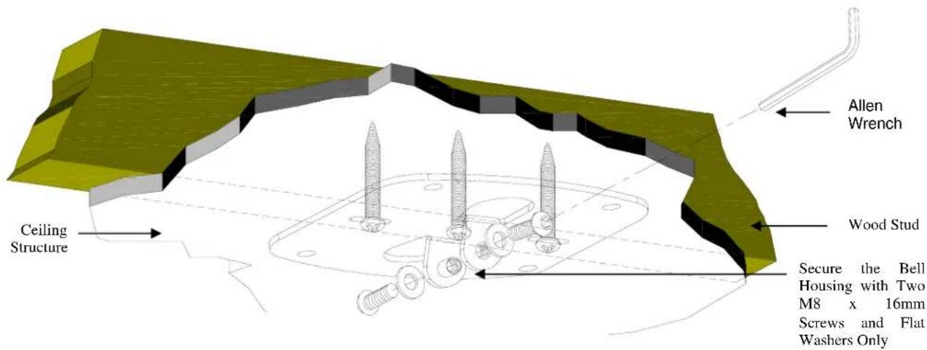
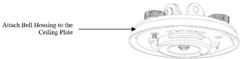
Figure 12
NOTE: Do not use the star washers on a close ceiling application.
Securing the Projector to the Upper Assembly
- Make sure the three-knurl knobs are loosened to fully expose to the "tri-lock" mounting plate in the base of the upper assembly.
- Carefully lift the projector and insert the mounting bracket mating special tri-lock cutout into the mating portion of the upper assembly.
- Once inserted rotate the projector and mounting bracket 180° and secure the rear safety knob first to prevent further rotation of the bracket in the upper assembly.
- Tighten the remaining two tension knurl knobs until the mount becomes rigid.
- The safety knob should line up with the alignment slot on the mounting bracket (Figure 13).
NOTE: Follow the number sequence prior to securing the projector to the upper assembly.
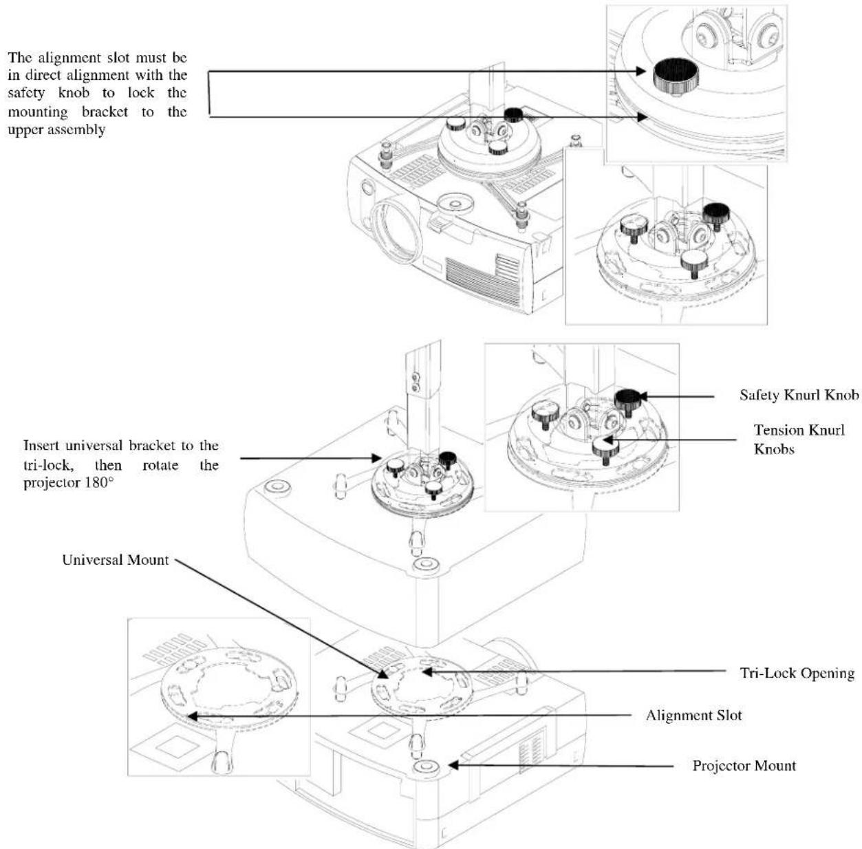
Figure 13
Final Adjustments
- With the projector secured in the mount and power on and signal supplied to the projector you can now proceed with the final height, tilt, and roll and yaw to optimize the projected image.
- The height can be adjusted by slightly loosening the two 8mm height adjustment screws and raising or lowering the projector (Figure 14).
- Once the height is achieved tighten the two screws.
- To adjust the tilt angle of the projector, slightly loosen the side M8 screws and tilt to the desired angle to the screen and firmly tighten the two M8 tilt adjustment screws (Figure 15).
- If roll adjustment is needed to square the images on the screen, slightly loosen the front and rear M8 screws and adjust to the desired angle then firmly tighten the two M8 roll adjustment screws (Figure 16).
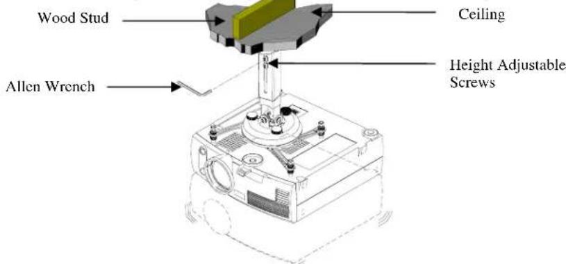
Figure 14
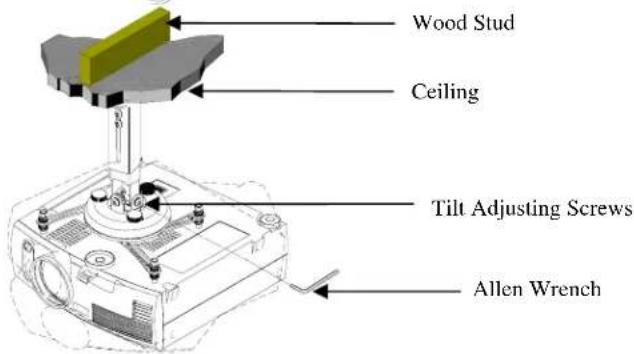
Figure 15
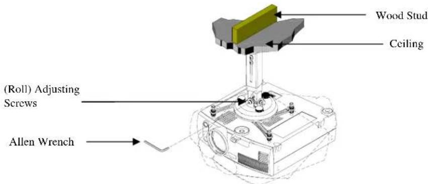
Figure 16
Installing the Plastic Caps
- Once all the final adjustments have been done, install the plastic caps on the leveling barrels (Figure 17).
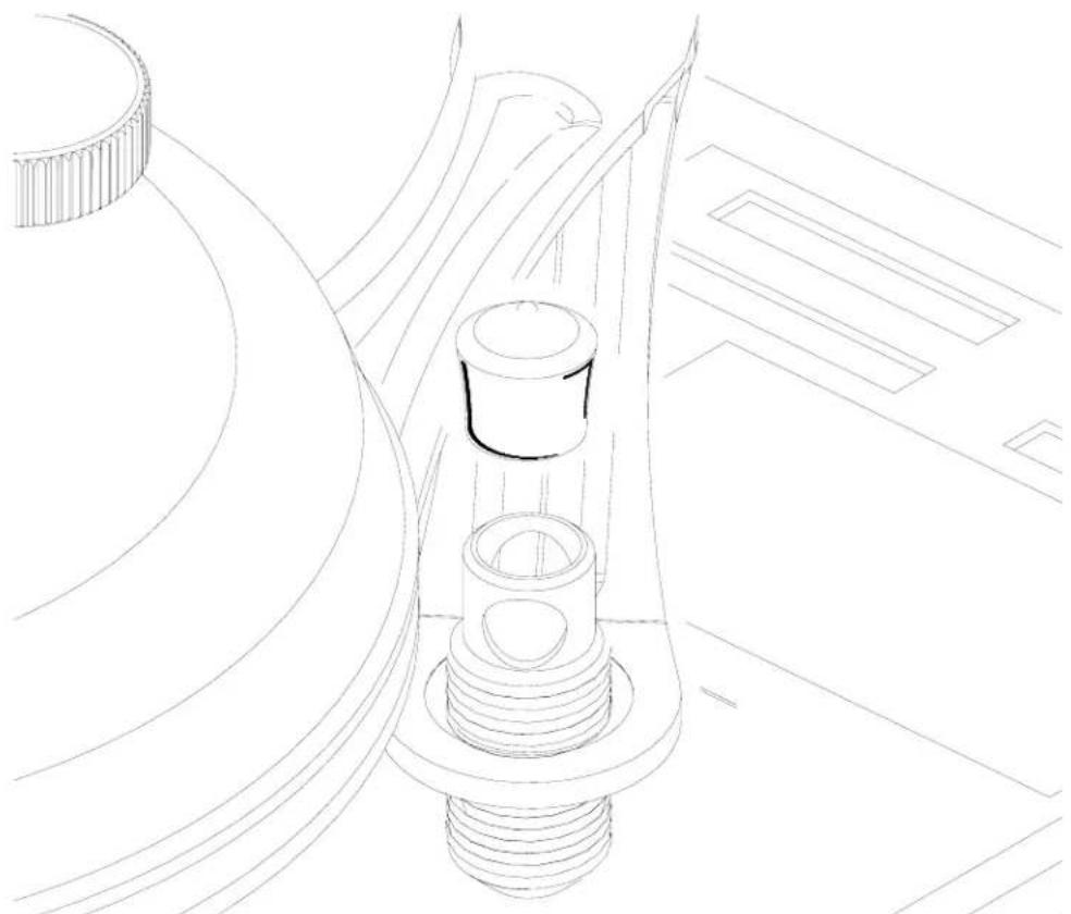
Figure 17
- EPSON
- TABLE OF CONTENTS
- WARRANTY
- LIMITED LIFETIME WARRANTY
- DISCLAIMER OF WARRANTY
- CONTACT PREMIER MOUNTS
- WARNING STATEMENTS
- WARNING
- PARTS LIST
- INSTALLATION TOOLS
- ELPMBUNI UNIVERSAL MOUNT ASSEMBLY
- PROJECTOR PREPARATION
- NOTE
- SECURING THE BRACKET TO THE PROJECTOR
- LEVELING THE MOUNTING BRACKET
- SECURING THE UPPER ASSEMBLY CEILING PLATE
- LOW-PROFILE INSTALLATION
- SECURING THE PROJECTOR TO THE UPPER ASSEMBLY
- FINAL ADJUSTMENTS
- INSTALLING THE PLASTIC CAPS
Brand : EPSON
Model : ELPMBUNI
Category : Projector