
ProCurve 5300xl - Switch HP - Free user manual and instructions
Find the device manual for free ProCurve 5300xl HP in PDF.
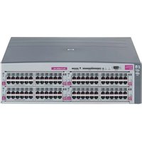


| Product Type | Modular Ethernet Switch |
| Series | HP ProCurve 5300xl |
| Form Factor | Chassis |
| Supported Slots | 4 or 8 module slots depending on model |
| Dimensions (H x W x D) | Approximately 22.6 x 44.2 x 40.6 cm (8.9 x 17.4 x 16 in) |
| Weight | Approximately 12.5 kg (27.6 lbs) without modules |
| Power Supply | Internal redundant hot-swappable power supply |
| AC Voltage | 100-240 VAC, 50/60 Hz |
| Switching Capacity | Up to 76.8 Gbps |
| Throughput | Up to 48 million packets per second |
| Layer Support | Layer 2 and basic Layer 3 (static routing) |
| Port Options | 10/100/1000BASE-T, 1000BASE-X, 10-GbE modules |
| Management | SNMP, CLI, web interface, console port |
| Features | Link aggregation, VLAN, QoS, ACL, spanning tree, IGMP snooping |
| Security | Port security, SSH, TACACS+ |
| Cooling | Fan tray, hot-swappable, side-to-side airflow |
| Mounting | Rack-mountable with included hardware |
| Operating Temperature | 0°C to 40°C (32°F to 104°F) |
| Operating Humidity | 15% to 95% non-condensing |
| Maintenance & Cleaning | Use a dry cloth for external cleaning; keep vents unobstructed |
| Spare Parts & Repairability | Hot-swappable power supplies, fans, and modules for easy replacement |
| General Information | Suitable for enterprise networks; supports advanced redundancy and high availability |
Frequently Asked Questions - ProCurve 5300xl HP
User questions about ProCurve 5300xl HP
0 question about this device. Answer the ones you know or ask your own.
Ask a new question about this device
Download the instructions for your Switch in PDF format for free! Find your manual ProCurve 5300xl - HP and take your electronic device back in hand. On this page are published all the documents necessary for the use of your device. ProCurve 5300xl by HP.
USER MANUAL ProCurve 5300xl HP
Installation and Getting Started Guide
ProCurve Series 5300xl Switches

Power over Ethernet Devices
ProCurve Switch 5300xl Series
Installation and Getting Started Guide
© Copyright 2001, 2005 - 2007 Hewlett-Packard Development Company, L.P.
Publication Number
5991-8597
December 2007
Applicable Products
ProCurve Switch 5308xl (J4819A)
ProCurve Switch 5372xl (J4848B)
ProCurve Switch 5348xl (J4849B)
ProCurve Switch 5304xl (J4850A)
ProCurve Switch 5304xl-G32 (J8166A)
ProCurve Switch 5308xl-G48 (J8167A)
Disclaimer
HEWLETT-PACKARD COMPANY MAKES NO WARRANTY OF ANY KIND WITH REGARD TO THIS MATERIAL, INCLUDING, BUT NOT LIMITED TO, THE IMPLIED WARRANTIES OF MERCHANTABILITY AND FITNESS FOR A PARTICULAR PURPOSE. Hewlett-Packard shall not be liable for errors contained herein or for incidental or consequential damages in connection with the furnishing, performance, or use of this material.
The information contained herein is subject to change without notice. The only warranties for HP products and services are set forth in the express warranty statements accompanying such products and services. Nothing herein should be construed as constituting an additional warranty. HP shall not be liable for technical or editorial errors or omissions contained herein.
Hewlett-Packard assumes no responsibility for the use or reliability of its software on equipment that is not furnished by Hewlett-Packard.
Warranty
See the Customer Support/Warranty booklet included with the product.
A copy of the specific warranty terms applicable to your Hewlett-Packard products and replacement parts can be obtained from your HP Sales and Service Office or authorized dealer.
Safety
Before installing and operating these products, please read the “Installation Precautions” in chapter 2, “Installing the Switch 5300xl Series”, and the safety statements in appendix C, “Safety and Regulatory Statements”.
Contents
1 Introducing the ProCurve Switch 5300xl Series
Front of the Switch....1-4
LEDs 1-5
LED Mode Select Button and Indicator LEDs 1-7
Console Port 1-8
Reset Button 1-8
Clear Button 1-8
Back of the Switch 1-9
Power Connector 1-9
Slot for Redundant Power Supply 1-9
Switch Features 1-10
2 Installing the Switch 5300xl Series
Included Parts 2-1
Installation Procedures 2-3
Summary 2-3
- Prepare the Installation Site 2-6
Cabling Infrastructure 2-6
Installation Location 2-7
-
Install Switch xl Modules 2-8
-
(Optional) Install Second Power Supply ..... 2-10
-
Verify the Switch Passes Self Test 2-12
LED Behavior: 2-13
- Mount the Switch 2-14
Rack or Cabinet Mounting 2-14
Horizontal Surface Mounting 2-16
Wall Mounting 2-17
-
Connect the Switch to a Power Source ..... 2-18
-
Connect the Network Devices ..... 2-18
-
(Optional) Connect a Console to the Switch ..... 2-19
Terminal Configuration 2-19
Direct Console Access 2-20
Telnet Console Access 2-20
Hot Swapping Switch Modules 2-21
Adding or Replacing Modules 2-21
Changing the Module Type 2-21
Example Network Topologies 2-22
Basic Connectivity 2-22
Use as an Edge Switch 2-23
3 Getting Started With Switch Configuration
Recommended Minimal Configuration 3-1
Using the Switch Setup Screen 3-2
Where to Go From Here 3-4
Using the IP Address for Remote Switch Management 3-5
Starting a Telnet Session 3-5
Starting a Web Browser Session 3-5
Configuring the ProCurve Access Controller xl Module (J8162A) ..... 3-7
740wl/760wl Configuration 3-7
Module Configuration 3-7
5300xl Switch Configuration 3-9
Configuring the ProCurve Wireless Edge Services xl Modules (J9001A, J9003A) 3-11
Configuring an IP Address for the Module 3-11
Configuring VLANs on the 5300xl Switch 3-13
Determining a Module Configuration Backup Process 3-13
Configuring Wireless LAN Services 3-13
4 Troubleshooting
Basic Troubleshooting Tips 4-1
Diagnosing with the LEDs 4-4
Proactive Networking 4-9
Hardware Diagnostic Tests 4-10
Testing the Switch by Resetting It 4-10
Checking the Switch LEDs 4-10
Checking Console Messages 4-10
Testing Twisted-Pair Cabling 4-11
Testing Switch-to-Device Network Communications 4-11
Testing End-to-End Network Communications 4-11
Restoring the Factory Default Configuration 4-12
Downloading New Code 4-13
HP Customer Support Services 4-13
Before Calling Support 4-13
A Specifications
Physical.... A-1
Electrical A-1
Environmental A-1
Acoustic A-2
Switch 5308xl and Switch 5372xl: A-2
Switch 5304xl and Switch 5348xl: A-2
Network Connectors.... A-2
Safety A-2
B Switch Ports and Network Cables
Switch Ports B-1
Twisted Pair ...... B-1
Fiber-Optic B-1
Cables B-2
Fiber-Optic Cables B-3
Copper Cables B-4
Twisted-Pair Cable/Connector Pin-Outs B-4
Straight-Through Twisted-Pair Cable for
10 Mbps or 100 Mbps Network Connections.... B-6
Cable Diagram B-6
Pin Assignments B-6
Crossover Twisted-Pair Cable for
10 Mbps or 100 Mbps Network Connection.... B-7
Cable Diagram B-7
Pin Assignments B-7
Straight-Through Twisted-Pair Cable for
1000 Mbps Network Connections B-8
Cable Diagram B-8
Pin Assignments B-8
C Safety and EMC Regulatory Statements
Safety Information C-1
Safety Information (China) C-7
EMC Regulatory Statements C-8
U.S.A. C-8
Canada C-8
Australia/New Zealand C-8
Japan C-8
Korea C-9
Taiwan C-9
Regulatory Model Identification Number C-9
D Recycle Statements
Waste Electrical and Electronic Equipment (WEEE) Statements ..... D-1
Index
Introducing the ProCurve Switch 5300xl Series
The ProCurve Switch 5300xl Series include the Switch 5304xl and its bundles, the Switch 5348xl and the Switch 5332xl-Gigabit, and the Switch 5308xl and its bundles, the Switch 5372xl and the Switch 5348xl-Gigabit. They are multi-port modular switches that provide Layer 3 routing features, and that feature low latency for high-speed networking.
This chapter describes your Switch 5300xl Series including:
■Front and back of the switches
■Features
■Switch operation overview
Switch 5304xl, Switch 5348xl and the Switch 5304xl-32G. The Switch 5304xl is available as an open 4-slot chassis (J4850A), as the Switch 5348xl bundle (J4849B) with two 24-port 10/100-TX xl Modules pre-installed, and as the Switch 5304xl-32G (J8166A) with two 16-port 100/1000-T xl Modules pre-installed.
ProCurve Switch 5304xl (J4850A)

ProCurve Switch 5348xl bundle (J4849B) with two 10/100-TX xl Modules preinstalled

Figure 1-1. Example 5304xl chassis and 5348xl bundle
ProCurve
Switch 5304xl-32G
bundle (J8166A)
with two 16 port
100/1000-T xl Modules
preinstalled

Figure 1-2. Example 5304-32G bundle
Switch 5308xl and Switch 5372xl and the Switch 5308xl-48G. The Switch 5308xl is available as an open 8-slot chassis (J4819A), as the Switch 5372xl bundle (J4848B) with three 24-port 10/100-TX xl Modules pre-installed and as the Switch 5308xl-48G bundle (J8167A) with three 16-port 100/1000-T xl Modules pre-installed.
ProCurve Switch5308xl (J4819A)

Figure 1-3. Example 5308xl chassis
ProCurve Switch 5372xl bundle (J4848B) with three 10/100-TX xl Modules preinstalled

Figure 1-4. Example 5372xl bundle
ProCurve Switch 5308xl-48G bundle (J8167A) with three 100/1000-T xl Modules preinstalled

Figure 1-5. Example 5308xl-48G bundle
See "Switch Features" on page 1-10 for a list of the switch modules that you can install in the ProCurve Switch 5300xl Series (modules available when this manual was printed).
Front of the Switch

Figure 1-6. Example front description
This illustration shows the 5348xl, but the labeling and descriptions apply to all of the ProCurve Switch 5300xl Series.
LEDs
As described in the next two tables, there are LEDs on the switch chassis and on the switch modules that keep you informed of the status of the switch and the network connections.
Table 1-1. Switch Chassis LEDs
| LEDs State Meaning | ||
| Power(green) | On The switch is receiving power.Off The switch is NOT receiving power. | |
| Fault(orange) | Off The normal state; indicates that there are no fault conditions on the switch.Flashing On On briefly at the beginning of switch self test after the switch is powered on or reset. If on for a prolonged time, the switch has encountered a fatal hardware failure, or has failed its self test. See chapter 4, “Troubleshooting” for more information. | |
| Self Test(green) | Off The normal operational state; the switch is not undergoing self test.On The switch self test and initialization are in progress after you have power cycled or reset the switch. The switch is not operational until this LED goes off. The Self Test LED also comes on briefly when you “hot swap” a module into the switch and the module is automatically self tested.Flashing A component of the switch has failed its self test. The Status LED for that component, for example a switch module, and the switch Fault LED will flash simultaneously. | |
| Status/Fan(green) | On The cooling fans are operating normally.Flashing One or more of the cooling fans have failed. The switch Fault LED will be flashing simultaneously. | |
| Status/Power(green - numbers corresponding to the power supply positions) | On A powersupply is installed in the position in the back of the switch corresponding to the number, and the supply is plugged in to an active AC power source. As shipped, the switch has a single power supply in position 1.Off A powersupply is not installed in the position corresponding to the number.Flashing The power supply installed in the position corresponding to the number is not plugged in to an active AC power source, or has experienced a fault. The switch Fault LED will be flashing simultaneously. | |
| LEDs State Meaning | ||
| Status/Modules(green - letters corresponding to the switch module slots) | On A module | is installed in the switch module slot corresponding to the letter and the module is undergoing or has passed self test. This also occurs when you install a module when the switch is already powered on ("hot swap"). |
| Off A module | is not installed in the switch module slot corresponding to the letter. | |
| Flashing | The module status LED flashes very briefly when a module is being hot swapped. If the LED flashes for a prolonged time, the module in the slot corresponding to the letter has failed self test or encountered some other fault condition. See chapter 4, "Troubleshooting" for a more information. | |
| LED Mode Select(3 green LEDs) | Act Indicates | that the port Mode LEDs are displaying network activity information. |
| FDx Indicates | that the port Mode LEDs are lit for ports that are in Full Duplex Mode. | |
| Max Indicates | that the port Mode LEDs are lit for ports that are operating at their maximum possible link speed -- for any Gigabit-capable connection, that would be 1000 Mbps; for the 10/100-TX ports and 100-FX ports, that would be 100 Mbps. | |
| ! | Indicates that specific error packets are being detected on the port. In this mode, the Mode LED for the port will flash briefly for each error packet that is detected, for example CRC errors or late collisions. See chapter 4, "Troubleshooting" for more information. | |
| ^ The flashing behavior is an on/off cycle once every 1.6 seconds, approximately. | ||
Table 1-2. Switch Module LEDs
The following LEDs are located on the modules themselves, one pair for each port.
| LED State Meaning | ||
| Link On Indicates the port is enabled and receiving a link beat signal (for the twisted-pair ports), or a strong enough light level (for the fiber-optic ports) from the connected device.Off One of these conditions exists:• no active network cable is connected to the port• the port is not receiving link beat or sufficient light• the port has been disabled through the switch console, the web browser interface, ProCurve Manager, or other network management tool.Flashing The port has failed self test. The switch Fault, Self Test LEDs, and appropriate module status LEDs will flash simultaneously. | ||
| Mode Depending on the mode selected, displays the following: network activity information, whether the port is configured for Full Duplex operation, maximum speed operation, or whether network errors are occurring on the port. See “LED Mode Select Button and Indicator LEDs” below for more information. | ||
| The flashing behavior is an on/off cycle once every 1.6 seconds, approximately. | ||
LED Mode Select Button and Indicator LEDs
To optimize the amount of information that can be displayed for each of the switch ports, the Switch 5300xl Series use a Mode LED for each port. The operation of this LED is controlled by the LED Mode Select button on the switch chassis, and the current selection is indicated by the mode indicator LEDs near the button. Press the button to change from one mode to the next.

Figure 1-7. Example Mode Select button and Mode LEDs
■If the Activity in Actator LED is lit, each port Mode LED displays activity information for the port—it flickers as network traffic is received and transmitted through the port.
■If the Full Duplex in Fdxator LED is lit, the port Mode LEDs light for those ports that are operating in full duplex.
■If the maximum speed in Maxator LED is lit, the port Mode LEDs light for those ports that are operating at their maximum possible link speed, for example 1000 Mbps on a 100/1000-T port.
■If the attention indicator LED is lit, each Mode LED lights briefly for each network event that might require operator attention, for example, late collisions or CRC errors. See chapter 4, "Troubleshooting" for more information.
Console Port
This port is used to connect a console to the switch by using the serial cable supplied with the switch. This connection is described under “Connecting a Console to the Switch” in chapter 2, “Installing the Switch 5300xl Series”. The console is a full-featured interface that can be used to configure, monitor, and troubleshoot the switch. It can be run on a PC, laptop, or handheld device emulating a VT-100 terminal, or on a standard VT-100 terminal.
Reset Button
This button is used to reset the switch while it is powered on. This action clears any temporary error conditions that may have occurred, executes the switch self test, and resets all network activity counters to zero. The counters are displayed in the switch console interface, the switch web browser interface, and through SNMP network management applications, such as ProCurve Manager.
Press the Reset button also after changing the module type that is installed in any of the switch module slots while the switch is powered on. In this case, the switch must be reset to initialize the new module type. See “Hot Swapping Switch Modules” on page 2-21.
Clear Button
This button is used for the following purposes:
■ Deleting Passwords - When pressed by itself for at least one second, the Clear button deletes any switch console access passwords that you may have configured. Use this feature if you have misplaced the password and need console access.
This button is provided for your convenience, but its presence means that if you are concerned with the security of the switch configuration and operation, you should make sure the switch is installed in a secure location, such as a locked wiring closet.
■ Restoring Factory Default Configuration - When pressed with the Reset button in a specific pattern, the Clear button clears any configuration changes you may have made through the switch console, the web browser interface, or SNMP management, and restores the factory default configuration to the switch. For the specific method to restore the factory default configuration, see “Restoring the Factory Default Configuration” in chapter 4, “Troubleshooting” of this manual.
Back of the Switch

Figure 1-8. Example back of 5300xl Series
Power Connector
The Switch 5300xl Series do not have a power switch; they are powered on when connected to an active AC power source. The switches automatically adjust to any voltage between 100-127 and 200-240 volts and either 50 or 60 Hz. There are no voltage range settings required.
Slot for Redundant Power Supply
A second, load-sharing redundant power supply (ProCurve Switch gl/xl RPS, J4839A) can be installed in the back of the Switch 5300xl Series. To provide true redundancy, this second power supply should be connected to a different AC power source from the other supply. Then, if one AC power source fails, the switch will continue to run.
Caution
The switch redundant power supply is hot swappable, but, as indicated by the caution statement on the power supply, it must be disconnected from AC power before being installed or removed.
Caution:

• Refer to the installation guide for proper power cord selection.
- Disconnect AC power from this power supply BEFORE installing or removing the supply. Otherwise, damage to the equipment may result.
Because the switch can run on a single supply, removing a redundant supply will not interrupt switch operation.
Switch Features
The features of the Switch 5300xl Series include:
■4 or 8 slots for installing any of the available Switch xl Modules.
Supported Modules: As of this printing, the supported xl modules includes:
- Access Control xl Module (J8162A) -- operates as an access controller (ProCurve Access Controller 720wl) for a wireless network and it must be connected to an access control server (either a ProCurve Access Control Server 740wl or a ProCurve Integrated Access Manager 760wl).
• 24-port 10/100-TX xl Module (J4820B)
• 4-port 100/1000-T xl Module (J4821B) - 4-port mini-GBIC xl Module (J4878B) -- into which you can install the supported mini-GBICs, the Gigabit-SX LC mini-GBIC (J4858A), the Gigabit-LX LC mini-GBIC (J4859A), the Gigabit-LH LC mini-GBIC (J4860A), and the 1000Base-T mini-GBIC (J8177B)
- 12 port 100-FX MTRJ xl Module (J4852A) - provides 12 100-FX ports with MT-RJ connectors for 100 Mbps networking over multimode fiber-optic cable.
- 16 port 10/100/1000Base-T xl Module (J4907A) – includes 14 10/100/1000-T ports and two dual personality ports: 10/100/1000-T or mini-GBIC
- 24-port 10/100-TX xl PoE Module (J8161A) -- which, when connected to a ProCurve 600 Redundant and External Power Supply(J8168A), can provide Power over Ethernet (PoE) power to 802.3af compliant devices. For more information on PoE power refer to the ProCurve PoE Planning and Implementation Guide. For more information on the J8161A module refer to the ProCurve Switch xl Modules Installation Guide.
Caution For safe and reliable operation, disconnect EPS cable before installing or removing J8161A modules. For more information refer to the ProCurve Switch xl Modules Installation Guide.
- 1-port 10-GbE xl Module (J8988A) -- into which you can install the supported transceivers, the ProCurve 10-GbE X2-SC SR Optic (J8436A), the ProCurve 10-GbE X2-SC LR Optic (J8437A), the ProCurve 10-GbE X2-SC ER Optic (J8438A), the ProCurve 10-GbE X2 CX4 Xcvr (J8440B), and the ProCurve 10-GbE CX4 Optical Media Converter (J8439A)
■the modules can be installed in any order and in any combination and can be “hot swapped”.
■the supported mini-GBICs can be hot swapped into the mini-GBIC xl Module.
■the supported transceivers can be hot swapped into the 10-GbE vl Module.
■high performance -- 76.8 Gbps switching fabric delivering 48 Mpps throughput.
■plug-and-play networking—all ports are enabled—just connect the network cables to active network devices and your switched network is operational.
■automatic learning of the network addresses in the switch's 16,000-address forwarding table, with configurable address aging value.
■full-duplex operation available on all ports.
■easy management of the switch through several available interfaces:
- web browser interface—an easy to use built-in graphical interface that can be accessed from common web browsers.
- console interface—a full featured, easy to use, VT-100 terminal interface for out-of-band switch management, or for telnet access to the switch. The console includes complete switch management through a command line interface (CLI) and a slightly reduced feature set accessible through an intuitive menu interface.
- ProCurve Manager—an SNMP-based graphical interface that is used to manage your entire network, included with your new switch.
- Supported by ProCurve Network Manager—an HP OpenView application that accurately displays your switch on network maps and provides a graphical interface for configuring and monitoring your switch.
■support for the Spanning Tree Protocol to eliminate network loops.
■support for up to 256 IEEE 802.1Q-compliant VLANs so you can divide the attached end nodes into logical groupings that fit your business needs.
■Layer 3 routing functionality:
- I P s t a t i c r o u t e s
- RIP V1 and V2
- IRDP - ICMP Router Discovery Protocol
- OSPF- Open Shortest Path First
- DHCP relay
■support for many other advanced features to enhance network performance, security, and control—for a description, see the Management and Configuration Guide that is on the ProCurve Web site, www.procurve.com.
Installing the Switch 5300xl Series
The Switch 5300xl Series is easily installed. They come with an accessory kit that includes the brackets for mounting the switch in a standard 19-inch telco rack, in an equipment cabinet, or on a wall. The switches have rubber feet already attached so they can be securely located on a horizontal surface. This chapter shows you how to install your Switch 5300xl Series.
Included Parts
The Switch 5300xl Series have the following components shipped with them:
■ ProCurve Switch 5300xl Series Installation and Getting Started Guide, this manual
■ProCurve Manager - CD ROM and booklet
■Customer Support/Warranty booklet
■Accessory kit (5065-6521 for the 8-slot Switch 5308xl, Switch 5372xl, and Switch 5308xl-G48; 5064-9943 for the 4-slot Switch 5304xl, Switch 5348xl, and Switch 5304xl-G32):
- two mounting brackets
- six 10 mm M4 screws to attach the mounting brackets to the switch
- four 5/8-inch number 12-24 screws to attach the switch to a rack
■Console cable
Installing the Switch 5300xl Series
Included Parts
■Power cord, one of the following:
| Australia/New Zealand | 8120-6803 |
| China | 8120-8377 |
| Continental Europe | 8120-6802 |
| Denmark | 8120-6806 |
| Japan | 8121-0606 |
| Switzerland | 8120-6807 |
| United Kingdom/Hong Kong/Singapore | 8120-8709 |
| United States/Canada/Mexico | 8121-0605 |
Japan Power Cord Warning
Installation Procedures
Summary
Follow these easy steps to install your switch. The rest of this chapter provides details on these steps.
- Prepare the installation site (page 2-6). Make sure that the physical environment into which you will be installing the switch is properly prepared including having the correct network cabling ready to connect to the switch, and having a good location for the switch. Please see page 2-5 for some installation precautions.
- Install switch modules (page 2-8). The Switch 5300xl Series have four or eight universal slots for installing any of the ProCurve Switch xl modules. The Switch 5372xl has three 24-port 10/100-TX xl Modules preinstalled, and the Switch 5348xl has two 24-port 10/100-TX xl Modules preinstalled. Depending on where you will install your Series 5300xl Switch, it may be easier to install the modules first. The modules are “hot swappable” though, so they can also be installed and removed after the switch is powered on.
Note Make sure you use only ProCurve Switch xl Modules in your Switch 5300xl Series.
- (Optional) Install second power supply (page 2-10). The Switch 5300xl Series have a slot in the back for installing a second, load-sharing power supply. If you have purchased this supply, it may be easier to install it before mounting the switch.
- Verify the switch passes self test (page 2-12). This is a simple process of plugging the switch into a power source and observing that the LEDs on the switch's front panel and on the modules show correct operation.
- Mount the switch (page 2-14). The Switch 5300xl Series can be mounted in a 19-inch telco rack, in an equipment cabinet, on a wall, or on a horizontal surface. Note that there are some limitations to the wall mounting orientations that are supported. Please see the installation details for more information.
-
Connect power to the switch (page 2-18). Once the switch is mounted, plug it in to the nearby main power source.
-
Connect the network devices (page 2-18). Using the appropriate network cables, connect other switches, hubs, routers, computers, servers, printers, and other network devices to the switch ports. For more information, see “Connect the Network Devices” on page 2-18.
Note The 10/100Base-TX ports on the 10/100-TX and PoE xl Modules have the
HP Auto-MDIX feature, and the 100/1000Base-T ports on the 100/1000-T xl Module comply with IEEE 802.3ab standard which includes the Auto MDI/MDI-X feature. These two features operate the same and allow you to use straight-through twisted-pair cable for all of your twisted-pair network connections.
- (Optional) Connect a console to the switch (page 2-19). You may wish to modify the switch's configuration, for example, to configure an IP address so it can be managed using a web browser or from an SNMP network management station. Configuration changes can be made easily through the switch's console interface.
At this point, the switch is fully installed. See the rest of this chapter if you need more detailed information on any of these installation steps.
| Installation PrecautionsFollow these precautions when installing your Series 5300xl Switch: | |
| WARNING | ■Devices installed in a rack or cabinet should be mounted as low as possible, with the heaviest device at the bottom and progressively lighter devices installed above.The rack or cabinet should be adequately secured to prevent it from becoming unstable and/or falling over.■Ensure a cover plate is installed on any empty switch power supply slot. A cover plate is required for safe operation, and to ensure proper switch cooling.■To avoid energy and mechanical hazards, never allow any part of your body, jewelry, tool, or other foreign object to enter any module or power supply slots. |
Installation Precautions (continued)
Cautions
■Ensure the power source circuits are properly grounded, then use the power cord supplied with the switch to connect it to the power source.
If your installation requires a different power cord than the one supplied with the switch and power supply, be sure the cord is adequately sized for the switch's current requirements. In addition, be sure to use a power cord displaying the mark of the safety agency that defines the regulations for power cords in your country. The mark is your assurance that the power cord can be used safely with the switch and power supply.
■When installing the switch, note that the AC outlet should be near the switch and should be easily accessible in case the switch must be powered off.
■Ensure the switch does not overload the power circuits, wiring, and over-current protection. To determine the possibility of overloading the supply circuits, add together the ampere ratings of all devices installed on the same circuit as the switch and compare the total with the rating limit for the circuit. The maximum ampere ratings are usually printed on the devices near the AC power connectors.
■Do not install the switch in an environment where the operating ambient temperature might exceed 40° C ( 104° F).
■Allow three to four inches of space around the sides and back of the switch to make sure the air flow for the switch is not restricted.
■Ensure that for any switch slot into which no module is installed, the cover plate is installed to cover the slot. A cover plate is required for safe operation, and to ensure proper switch cooling. For safety, you should never have more than one module slot uncovered at a time while the switch is powered on.
■For safe and reliable operation, disconnect EPS cable before installing or removing J8161A modules. For more information refer to the ProCurve Switch xl Modules Installation Guide.
1. Prepare the Installation Site
Cabling Infrastructure
Ensure the cabling infrastructure meets the necessary network specifications. See the following table for cable types and lengths, and see appendix B, "Switch Ports and Network Cables" on page B-1 for more information:
Table 2-1. Summary of Cable Types to Use with the Switch
| Port Type Cable Type Length Limits | ||
| Twisted-Pair Cables | ||
| 10/100/1000Base-T For either 10, 100 Mbps or 1000 Mbps operation:Category 5 or better, 100-ohm UTP or shielded twisted-pair (STP) balanced cable. For 1000 Mbps (gigabit) operation, Category 5e cabling or better is recommended. | 100 metersNote: The ProCurve 10/100/1000-T xI Modules and 100/1000-T Transceiver are compatible with the IEEE 802.3ab standard including the "Auto MDI/MDI-X" feature, which allows use either straight-through or crossover twisted-pair cables for connecting to any network devices including end nodes, such as computers, or to other switches, hubs, and routers.The Auto MDI/MDI-X feature only works when the port is in auto-negotiation mode. | |
| Fiber Optic Cables | ||
| Gigabit-SX(on Gigabit-SX-LC mini-GBIC) | Multimode fiber-optic cables fitted with LC connectors | 220 meters to 550 meters depending on the cable used. See "Fiber-Optic Cables" on page B-3 for more information. |
| Gigabit-LX(on Gigabit-LX-LC mini-GBIC) | Single-mode fiber-optic cables fitted with LC connectors.The multimode cables specified for the Gigabit-SX mini-GBIC may also be used, but a mode-conditioning patch cord may be needed — See the Installation Guide that came with your module for more information. | • single-mode cable = 10 kilometers• multimode cable = 550 meters |
| Gigabit-LH(on Gigabit-LH-LC mini-GBIC) | The same single-mode fiber-optic cables as for Gigabit-LX. | • 70 kilometers |
| Note:Gigabit-LH - The transmission distances are dependent on the particular fiber loss and coupling loss involved, among other factors, and can be estimated from the optical loss budget. For distances less than 20km, a 10dB attenuator must be used. For distances between 20km and 40km, a 5dB attenuator must be used. Attenuators can be purchased from most cable vendors. | ||
| 10-GbE SR Multimode fiber-optic cable designed for Gigabit Ethernet: 62.5/125 μm (core/cladding) diameter or 50/125 μm, low metal content, complying with the ITU-T G.652 and ISO/IEC 793-2 Type B1 standards. | ■ 62.5 μm cable:• 160 Mhz/km = 2-26 meters• 200 Mhz/km = 2-33 meters■ 50 μm cable:• 400 Mhz/km = 2-66 meters• 500 Mhz/km = 2-82 meters• 2000 Mhz/km = 2-300 meters | |
| 10-GbE LR | 9/125 μm (core/cladding) diameter, low metal content, single mode fiber-optic cables, complying with the ITU-T G.652 and ISO/IEC 793-2 Type B1 standards. | single-mode cable: 2-10 kilometers |
| 10-GbE ER | 9/125 μm (core/cladding) diameter, low metal content, single mode fiber-optic cables, complying with the ITU-T G.652 and ISO/IEC 793-2 Type B1 standards. | single-mode cable: 2-30 kilometers (40 kilometers, on an engineered fiber optic link that meets standards in the specification). |
| Note: Conditioning patch cord cables are not supported on 10-GbE. | ||
| CX4 Media Converter | 12 fiber 50/125 μm (core/cladding) diameter, multimode Fiber ribbon cable. 12 fiber 62.5/125 μm (core/cladding) diameter, multimode Fiber ribbon cable is also supported. | 50 μm cable or 62.5 μm cable: 100 meters |
Copper Cables
| Port Type Cable Specifications Length Limit |
CX4 Shielded twiststed-pair cables complying with the 802.3ak standard.
0.5-15 metersCX4
Installation Location
Before installing the switch, plan its location and orientation relative to other devices and equipment:
■In the front of the switch, allow at least 7.6 cm (3 inches) of space for the twisted-pair and fiber-optic cabling.
In the back of the switch, allow at least 10.2 cm (4 inches) of space for the power cord and cooling.
■On the sides of the switch, leave at least 7.6 cm (3 inches) for cooling.
2. Install Switch xl Modules
Install switch modules into the slots as shown in the illustration below. For installation details, see the instructions in the manual that comes with the module.
Caution
Make sure you install only ProCurve Switch xl Modules. Switch gl and vl Modules will fit into your Switch xl slots, but they will not operate.
Avoid any electrostatic discharge problems by handling the modules only by their bulkheads.
The slot cover can be removed, and the module can be installed with either a flat-bladed or Torx T-10 screwdriver. Retain the slot cover for future use.
Module Installation Notes
■Any of the supported Switch xl Modules can be installed in any of the slots.
■The modules can be “hot swapped”, installed after the switch is already powered on, and normally will be immediately operational. But, if you are replacing a module with a different type than what was previously installed in the slot, the switch must be rebooted after the module is installed. See “Hot Swapping the Switch Module” on page 2-21.
■The modules employ “low-force” connectors. Using high force to insert the modules is not needed and should not be used.
■Ensure you fully insert the modules. That is, press the module into the slot until the bulkhead on the module is contacting or is very close to contacting the front face of the switch chassis.
■Once the module is fully inserted, ensure that you screw in the two retaining screws to secure the module in place. The screws should be tightened until they are secure, but not overtightened.
■If you do not use one or more of the slots, ensure the slot cover plate is still attached over the slot for safe operation and proper switch cooling. For safety, you should not have more than one module slot uncovered at a time.

Figure 2-1. Installing a module

Figure 2-2. Tighting module retaining screws
3. (Optional) Install Second Power Supply
A second, load-sharing redundant power supply (ProCurve Switch gl/xl/vl RPS, J4839A) can be installed in the back of the switch. To provide true redundancy, this second power supply should be connected to a different AC power source from the other supply. Then, if one AC power source fails, the switch will continue to run. Each supply provides enough power to operate a fully loaded switch, so even if one fails, the switch will continue to operate normally.
Install the second power supply into power slot number 2 as shown in the illustration on the next page.
The slot cover can be removed with either a flat-bladed or Torx T-10 screw-driver. Retain the slot cover for future use.
Caution
The switch power supplies are hot swappable; they can be installed while the switch is receiving power from the supply in the other slot. But, as indicated by the caution statement on the power supply, the supply must not be connected to AC power before being installed.
- Refer to the installation guide for proper power cord selection.
- Disconnect AC power from this power supply BEFORE installing or removing the supply. Otherwise, damage to the equipment may result.

Caution:
For safety and proper switch cooling, if either of the power supply slots are not being used, make sure to attach the cover plate over the slot. Please see the “Installation Precautions” on page 2-5 for more information.
For installation details, see the instructions in the manual that comes with the power supply.
Insert the power supply into the opening, then slide it all the way in until it connects to the switch. The power supply face plate will be flush with the back face of the switch.
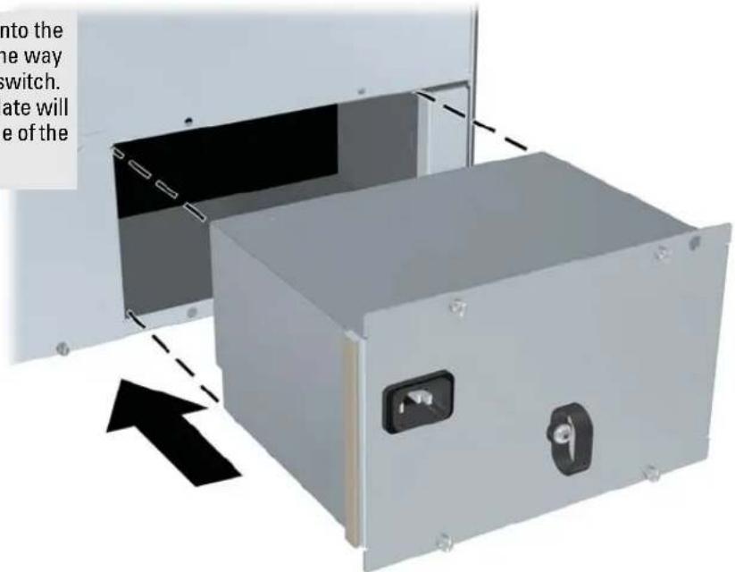
Figure 2-3. Installing a power supply
Once the power supply is installed, ensure you tighten the four retaining screws that hold it in place. The screws can be tightened with either a flat-bladed or Torx T-10 screwdriver. Be careful not to overtighten the screws.
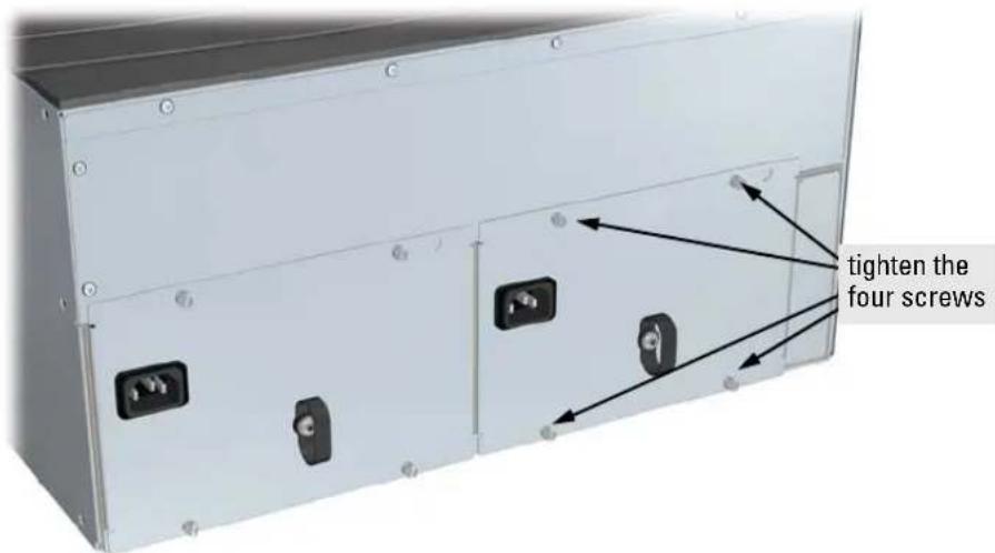
Figure 2-4. Tighting the power supply retaining screws
4. Verify the Switch Passes Self Test
After you have installed any modules and the optional second power supply, but before mounting the switch in its network location, you should first verify it is working properly by plugging it into a power source and verifying it passes its self test.
If you have installed a second power supply, repeat these procedures with the second power supply to verify it works correctly also.
- Connect the power cord supplied with the switch to the power connector on the back of the switch, and then into a properly grounded electrical outlet.

Figure 2-5. Connecting the power cord
Note The Switch 5300xl Series does not have a power switch. They are powered on when the power cord is connected to the switch and to a power source.
If your installation requires a different power cord than the one supplied with the switch, please see the "Installation Precautions" on page 2-5.
- Check the LEDs on the switch and on each of the switch modules. The LED behavior is described on the next page.
If the LED display is different than what is described, especially if the Fault LED stays on for more than approximately 120 seconds or it starts flashing, the self test has not completed correctly. Refer to chapter 4, "Troubleshooting" for diagnostic help.
switch module LEDs: Link and Mode LEDs for each port

Figure 2-6. Switch LEDs
When the switch is powered on, it performs its diagnostic self test. The entire download, initialization, and self test process can take up to 2 minutes for a fully loaded chassis, depending on the number and type of modules installed in the switch.
LED Behavior:
During the self test:
■ Initially, Power and Fault, and all the switch chassis LEDs are on. Then, after approximately 30 seconds, all the module LEDs go on as the modules receive power and code is downloaded to them, the Fault LED goes off, and the chassis LEDs go off except Power, Self Test, Fan Status, and Power Status.
■When the download of code to the modules is completed, the module LEDs go off. You may see each port LED go on briefly, in sequence, as the port is tested.
■ For the duration of the self test, the Self Test LED stays on.
When the self test completes successfully:
■ The Power LED stays on, and the Status LEDs on the switch chassis stay on for the devices installed: one for each switch module installed, one for each power supply installed, and one for all the fans.
■ The Fault and Self Test LEDs are off.
■The port LEDs on the switch modules go into their normal operational mode:
- If the ports are connected to active network devices, the Link LEDs stay on and the Mode LEDs behave according to the mode selected. In the default mode (Activity), the Mode LEDs should flicker showing network activity on the port.
- If the ports are not connected to active network devices, the LEDs will stay off.
5. Mount the Switch
After the modules and optional power supply are installed and you have verified the switch passes self test, you are ready to mount the switch in a stable location. The Switch 5300xl Series can be mounted in these ways:
■in a rack or cabinet
■on a horizontal surface
■on a wall
Rack or Cabinet Mounting
The Switch 5300xl Series is designed to be mounted in any EIA-standard 19-inch telco rack or in an equipment cabinet such as a server cabinet. If you are installing the switch in an equipment cabinet, please see the “Equipment Cabinet Note” on page 2-16.
Caution
For safe operation, please read the "Installation Precautions" on page 2-5 before mounting the switch.
- Use a #1 Phillips (cross-head) screwdriver and attach the mounting brackets to the switch with the included 10-mm M4 screws.
For the Switch 5304xl and Switch 5348xl, each bracket is attached with two screws, and for the Switch 5308xl and Switch 5372xl each bracket is attached with three screws as shown in the illustrations on the next page.

Figure 2-7. Attaching brackets to the switch 5308xl
- Partially install a screw (5/8-inch number 12-24) into the top hole of a pair of holes that are 0.5 inches apart in each rack/cabinet upright as shown in the illustration below. Ensure that the screws are at the same level in each upright.

Figure 2-8. Partially installed screw for bracket notch
- Place the switch in the rack and lower it so the notches in the bottom of the bracket slide onto the screws, then tighten these screws.

Figure 2-9. Setting the bracket notch
Installing the Switch 5300xl Series
Installation Procedures
- Install the other number 12-24 screw into the upper hole in each bracket. Tighten these screws.
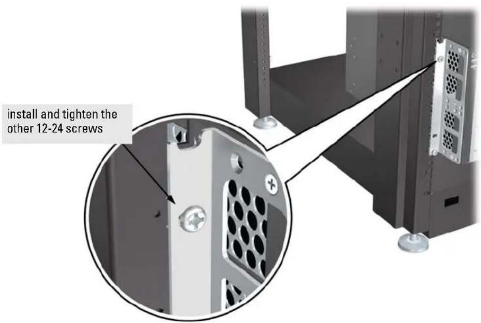
Figure 2-10. Installing the final rack mounting screw
Equipment Cabinet Note
If you are installing the switch in an equipment cabinet, in place of the 12-24 screws supplied with the switch, use the clips and screws that came with the cabinet. Plan which four holes you will be using in the cabinet and install all four clips and partially install the two bottom screws, as described in step 2 on the previous page, before proceeding to step 3.
Horizontal Surface Mounting
Place the switch on a table or other horizontal surface. Use a sturdy surface in an uncluttered area. You may want to secure the networking cables and switch power cord to the table legs or other part of the surface structure to help prevent people from tripping over the cords.
Note
Ensure the air flow is not restricted around the sides and back of the switch.
Wall Mounting
The mounting brackets supplied with the switch allow you to mount it on a wall. The illustrations below show mounting a Switch 5308xl/5372xl. The Switch 5304xl/5348xl would be mounted in a similar way.
Caution
For safe operation, do not install the switch with the vents or fans facing downward. The only recommended and supported wall mounting orientation is with the unit upright and the modules facing out, as shown in the illustrations below.
Additionally, the switch should be mounted only to a wall or wood surface that is at least 1/2-inch plywood or its equivalent.
- Use a #1 Phillips (cross-head) screwdriver and attach the mounting brackets to the switch with the included 10-mm M4 screws.

Figure 2-11. Attaching brackets to the rear of the switch
- Attach the switch to the wall or wood surface with four 5/8-inch number 12 wood screws or larger (not included).
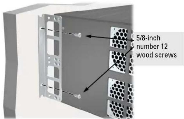
Figure 2-12. Mounting to a wall
6. Connect the Switch to a Power Source
- Plug the included power cord into the switch's power connector and into a nearby properly grounded AC power source.
If you have installed a redundant power supply module into the switch, it should be connected to a separate AC power source. Then, if there is a power outage from one of the AC sources, the switch will continue to operate by power coming from the other source.
See the ProCurve Switch gl/xl/vl RPS Installation Guide for additional information.
- Re-check the LEDs during self test. See "LED Behavior" on page 2-13.
7. Connect the Network Devices
The type of network connections you will need to use depends on the types of switch modules you have installed in your Series 5300xl Switch. See the documentation accompanying the modules for cabling configurations and procedures for those modules.
In general for all the modules, when a network cable from an active network device is connected to the switch, the Link LED for the switch port should go on. If the Link LED does not go on, use the table below to help solve the problem, and see the module documentation for troubleshooting procedures.
Condition Diagnostic Tip
Port LED is still off when a cable is connected
Try the following procedures:
- For the indicated port, verify both ends of the cabling, at the switch and the connected device, are securely connected.
- Verify the connected device and switch are both powered on and operating correctly.
-
Verify you have used the correct cable type for the connection:
-
for all twisted-pair connections, the RJ-45 connectors on the Switch 5300xl Series allow you to use either "straight-through" cable or "crossover" cable when the port is in the "Auto" configuration.
- for fiber-optic connections, verify the transmit port on the switch is connected to the receive port on the connected device, and the switch receive port is connected to the transmit port on the connected device.
See appendix B, "Switch Ports and Network Cables" for information on cables.
- Verify the port has not been disabled through a switch configuration change.
- Verify the connection parameters in the configurations of the switch port and the connected device match. Mismatched configurations are a frequent cause of connection problems.
You can use the console interface, or, if you have configured an IP address on the switch, use the web browser interface, or ProCurve Manager network management software to determine the state and configuration of the port and re-enable the port if necessary.
- If the other procedures don't resolve the problem, try using a different port or a different cable.
8. (Optional) Connect a Console to the Switch
The Switch 5300xl Series have a full-featured, easy to use console interface for performing the following tasks:
■Monitor switch and port status and observe network activity counters
■Modify the switch's configuration
■Read the event log and access diagnostic tools to help in troubleshooting
■Download new software to the switch
■Add passwords and other security features to control access to the switch from the console, web browser interface, and network management stations
The console can be accessed through these methods:
■ Out-of-band: Connect a PC or VT-100 terminal, to be used as a console, directly to the switch using the serial cable that comes with the Switch 5300xl Series. If the PC or terminal has a 25-pin serial connector, you can use a readily available 9-pin to 25-pin serial cable, or attach a 9-to-25 pin straight-through adapter to the PC end of the cable.
In-Band: Access the console using telnet from a PC or UNIX station on the network, and a VT-100 terminal emulator. This method requires that you first configure the switch with an IP address and subnet mask by using either out-of-band console access or through DHCP/Bootp.
The Switch 5300xl Series can simultaneously support one out-of-band console session through the Console Port and one in-band telnet session.
Terminal Configuration
To connect a console to the switch, configure the PC terminal emulator as a VT-100 or DEC VT-100 (ANSI) terminal, or use a VT-100 terminal and configure it to operate with these settings:
■any baud rate from 2400 to 115200 (the switch automatically senses the speed)
■8 data bits, 1 stop bit, no parity, and flow control set to None
■for Windows Terminal program, also disable (unchecked) the “Use Function, Arrow, and Ctrl Keys for Windows” option
■for the Hilgrave HyperTerminal program, select the "Terminal keys" option for the "Function, arrow, and ctrl keys act as" parameter
If you want to operate the console using a different configuration, ensure you change the settings on both the terminal and on the switch. Change the switch settings first, then change the terminal settings, and reestablish the console session.
Direct Console Access
To connect a console to the switch, follow these steps:
- Connect the PC or terminal to the switch's Console Port using the console cable included with the switch. (If your PC or terminal has a 25-pin serial connector, first attach a 9-pin to 25-pin straight-through adapter to the PC end of the console cable.)
- Turn on the terminal or PC's power and, if using a PC, start the PC terminal program.
- Press the Enter key two or three times and you will see the copyright page and the message "Press any key to
![graph TD A["HP port"] --> B["Switch Cable"] B --> C["PC running a terminal emulator program, or a VT-100 terminal"] D["PC running a terminal emulator program, or a VT-100 terminal"] --> E["PC running a terminal emulator program, or a VT-100 terminal"]](/content/2026/08/1575291/images/6f5cd9f69f477946d9f137df2080e12449e95866643fdba44021d996fe080800.jpg)
Figure 2-13. Connecting a console
continue". Press a key, and you will then see the switch console CLI prompt.
Telnet Console Access
To access the switch through a telnet session, follow these steps:
- Ensure the switch is configured with an IP address and that the switch is reachable from the telnet workstation (for example by using a Ping command to the switch's IP address)
- Start the telnet program and connect to the switch's IP address.
- You will see the copyright page and the message "Press any key to continue". Press a key, and you will then see the switch console CLI prompt.
If you want to continue with console management of the switch at this time through either a direct connection or a telnet session, see chapter 3, “Getting Started With Switch Configuration” for some basic configuration steps. For more detailed information, refer to the Management and Configuration Guide which is on the ProCurve Web site, www.procurve.com.
Hot Swapping Switch Modules
The switch modules can be “hot swapped”, that is installed or replaced while the switch is powered on (See Module Installation Notes on page 2-8). The procedures differ slightly, though between adding new modules to an empty slot or replacing modules with the same type, and exchanging the module with a different type.
Adding or Replacing Modules
If a module has to be replaced with one of the same type, or you are expanding the switch capability by adding a module in a slot where one was not previously installed (since the last switch reboot), the replaced or new module is immediately operational; there is no interruption to the switch operation.
Changing the Module Type
If you exchange a module with a different type of module though, for example a 100/1000-T xl Module is installed in place of a 10/100-TX xl Module that was in the slot, the switch must be rebooted after the new module is installed so the switch processor can properly initialize and configure the new module type.
You can reboot the switch by any of the following methods:
■Pressing the Reset button on the front of the switch.
■Unplugging and plugging in the power cord (power cycle). If two power supplies are installed, both power cords would have to be unplugged.
■ Issuing the boot command from the switch console CLI, or selecting the Reboot Switch option from the switch console menu, the web browser interface, or ProCurve Manager.
Until the switch is rebooted, the module will not operate and the Module Status LED for the affected slot will continue to flash.
Example Network Topologies
This section shows you a few example network topologies in which the Switch 5300xl Series can be implemented. For more topology information, see the ProCurve Networking Web site, www.procurve.com.
Basic Connectivity
![graph TD A["server connected by a Gigabit link"] --> B["switch 5300xl"] C["twisted-pair straight-through or crossover"] --> B D["PCs and peripherals"] --> B E["Computer"] --> B F["Computer"] --> B G["Computer"] --> B H["Computer"] --> B I["Computer"] --> B J["Computer"] --> B](/content/2026/08/1575291/images/4448d733b44869e8afab737888190c373e554d900de6e6acf22abc72615fd81c.jpg)
Figure 2-14. Basic topology
The Switch 5300xl Series can provide basic network connectivity to a high number of users. End nodes, printers and other peripherals, and servers can be easily connected, as shown in the above illustration.
Notice the end node devices are connected to the switch by either straight-through or crossover twisted-pair cables. Either cable type can be used because of the "HP Auto-MDIX" feature on the 10/100-TX xl Modules and the standard "Auto MDI/MDI-X" feature on the 100/1000-T xl Transceiver to which the server is connected. The six twisted-pair ports on the 100/1000-T xl Module also support the "Auto MDI/MDI-X" feature.
Use as an Edge Switch

When your network expands and the users need to access resources beyond the edge of the local network, the Switch 5300xl Series are excellent platforms for that expansion. With the flexibility of 4 or 8 slots, the high port count 10/100-TX xl Module for local connections, and the availability of Gigabit speeds through either the Gigabit Transceiver xl Module or the 100/1000-T xl Module, the Switch 5300xl Series can provide that access beyond the edge for a high number of network users.
In the above illustration, two Switch 5308xls are connected to a ProCurve Routing Switch 9308, which can serve as a campus backbone or core switch.
The 1000 Mbps fiber-optic connections between the two Switch 5308xls and the Routing Switch 9308 is by way of Gigabit-LX mini-GBICs installed in mini-GBIC xl Modules in the Switch 5308xls and Gigabit-LX ports on the Routing Switch 9308. With the Gigabit-LX connections, the distance between the Switch 5308xls and the Routing Switch 9308 can be up to ten kilometers.
The connections are trunked, through a configuration change on the Switch 5308xl, to provide redundancy and load sharing for higher bandwidth.
Installing the Switch 5300xl Series
Example Network Topologies
This example configuration shows connectivity using a Switch Access Controller xl Module (J8162A) as a 720 access controller for a wireless network. Remember the Access Controller xl Module must be connected to an access control server (either a ProCurve Access Control Server 740wl or a ProCurve Integrated Access Manager 760wl).
![graph TD A["switch 5300xl"] --> B["Server 740/760"] B --> C["Access Points"] C --> D["Printer 1"] C --> E["Printer 2"] C --> F["Printer 3"] C --> G["Printer 4"] C --> H["Printer 5"] C --> I["Printer 6"]](/content/2026/08/1575291/images/1d3e1d748059c2b08df66b5de338e3a3c04d9dcf14cf95f96873ef98cf6accad.jpg)
Figure 2-16. Topology integrating an Access Controller module
Used as an Aggregation Switch
![graph TD A[" laptop"] --> B[" switch 5300xl "] C[" laptop"] --> D[" switch 5300xl "] E[" laptop"] --> F[" switch 5300xl "] G[" laptop"] --> H[" switch 5300xl "] I[" switch 5300xl "] --> J[" switch 8212zl "] K[" switch 5300xl "] --> J L[" switch 5300xl "] --> J M[" switch 5300xl "] --> J N[" switch 5…](/content/2026/08/1575291/images/8151e4c6043699c725a165c13d64e2508938560006ea1f07d2772fa7579a7ea7.jpg)
Figure 2-17. 10-GbE Aggregation Topology
The J8988A module in the Switch 5300xl Series will provide customers with a 10-GbE uplink connection (expected throughput is 2.5 to 7 Gbps, depending on packet size). Traffic from a single MAC SA to a single MAC DA cannot exceed 1 Gbps. Each Switch 5300xl Series can support up to four J8988A modules. The 10-GbE module supports trunking – however, each trunk will support at most two 10-GbE ports, and 10-GbE ports cannot be mixed with other port speeds in the trunk.
If more than two J8988A ports are added to an IEEE 802.3ad (LACP) dynamic trunk the remaining ports beyond the first two, as per the LACP specification, are placed in a "standby" mode. All four ports could be placed in a dynamic trunk. Two ports will remain on "standby" and be blocked, and two ports will be added to the dynamic trunk. If one (or both) of the ports in the dynamic trunk are disabled or disconnected, the highest priority "standby" port(s) will then be added to the trunk and the disabled/disconnected port(s) will be removed from the trunk. This works just like 10/100/1000 ports.
Getting Started With Switch Configuration
This chapter is a guide for using the console Switch Setup screen to quickly assign an IP (Internet Protocol) address and subnet mask to the switch, set a Manager password, and, optionally, configure other basic features.
For more information on using the switch console and the other switch management interfaces: the web browser interface and the SNMP management tool, ProCurve Manager, please see the Management and Configuration Guide which is on the ProCurve Web site, www.procurve.com.
Recommended Minimal Configuration
In the factory default configuration, the switch has no IP (Internet Protocol) address and subnet mask, and no passwords. In this state, it can be managed only through a direct console connection. To manage the switch through in-band (networked) access, you should configure the switch with an IP address and subnet mask compatible with your network. Also, you should configure a Manager password to control access privileges from the console and web browser interface. Other parameters in the Switch Setup screen can be left at their default settings or you can configure them with values you enter.
Many other features can be configured through the switch's console interface, to optimize the switch's performance, to enhance your control of the network traffic, and to improve network security. Once an IP address has been configured on the switch, these features can be accessed more conveniently through a remote Telnet session, through the switch's web browser interface, and from an SNMP network management station running a network management program, such as ProCurve Manager. For a listing of switch features available with and without an IP address, refer to “How IP Addressing Affects Switch Operation” in the Management and Configuration Guide which is on the ProCurve Web site, www.procurve.com.
For more information on IP addressing, refer to “IP Configuration” in the Management and Configuration Guide.
Note By default, the switch is configured to acquire an IP address configuration from a DHCP or Bootp server. To use DHCP/Bootp instead of the manual method described in this chapter, see “DHCP/Bootp Operation” in the Management and Configuration Guide which is on the ProCurve Web site, www.procurve.com.
Using the Switch Setup Screen
The quickest and easiest way to minimally configure the switch for management and password protection in your network is to use a direct console connection to the switch, start a console session, and access the Switch Setup screen.
- Using the method described in the preceding section, connect a terminal device to the switch and display the switch console command (CLI) prompt (the default display).
The CLI prompt appears displaying the switch model number:
ProCurve Switch 5308xl
- At the prompt, enter the setup command to display the Switch Setup screen. The following illustration is an example of a Setup screen with default settings.
![ProCurve Switch 5308x 4-Mar-20€5 17:02:05 ==================== CONSOLE - MANAGER MODE ==================== Switch Setup System Name : ProCurve Switch 5308x System Contact : Manager Password : Confirm Password : Logon Default : CLI Time Zone [0] : 0 Community Name : public Spanning Tree Enabled [No]…](/content/2026/08/1575291/images/6077c8dee727c9d1dead20a8a4825df79082c0d2bcfbcc0b6cb0d49db9aa4a44.jpg)
-
Use the Tab key to select the Manager Password field and enter a manager password of up to 16 characters.
-
Tab to the IP Config (DHCP/Bootp) field and use the Space bar to select the Manual option.
- Tab to the IP Address field and enter the IP address that is compatible with your network.
- Tab to the Subnet Mask field and enter the subnet mask used for your network.
- Press Enter, then S (for S_ave).
The following is information on the fields in the Setup screen. For more information on these fields, see the Management and Configuration Guide which is on the ProCurve Web site, www.procurve.com:
Parameter Default
| System Name blank Optional; up to 25 characters, including spaces | ||
| System Contact blank Optional; up to 48 characters, including spaces | ||
| Manager Password blank Recommended; up to 16 characters (no blank spaces) | ||
| Logon Default CLI The default setting selects the command line interface for console access.The alternative is the Menu interface. | ||
| Time Zone 0 (none) Optional; 1440 to -1440. The number of minutes your location is to the West (-) or East (+) of GMT. | ||
| Community Name public Default setting recommended. | ||
| Spanning Tree Enabled | No | Default setting recommended unless STP is already running on your network or the switch will be used in complex network topologies. |
| Default Gateway | blank | Recommended; Enter the IP address of the next-hop gateway node if network traffic needs to be able to reach off-subnet destinations. |
| Time Sync Method | TimeP | Optional; The protocol the switch uses to acquire a time signal. The options are SNTP and TimeP. |
| TimeP Mode | Disabled Synchronizes the time kept on the switch to the TimeP server. | |
| IP Config | DHCP/Bootp | Set to Manual unless a DHCP/Bootp server is used on your network to configure IP addressing. |
| IP Address | xxx.xxx.xxx.xxx | Recommended; If you set IP Config to Manual, then enter an IP address compatible with your network. |
| Note: The IP address and subnet mask assigned for the switch must be compatible with the IP addressing used in your network. For more information on IP addressing, see the Management and Configuration Guide which is on the ProCurve Web site, www.procurve.com. | ||
| Subnet Mask | xxx.xxx.xxx.xxx | Recommended; If you entered an IP address, then enter a subnet mask compatible with your network. |
Where to Go From Here
The above procedure configures your switch with a Manager password, IP address, and subnet mask. As a result, with the proper network connections, you can now manage the switch from a PC equipped with Telnet, a web browser interface, or from an SNMP-based network management station using a tool such as ProCurve Manager.
Some basic information on managing your switch is included in the next section. For more information on the console, web browser, and SNMP management interfaces and all the features that can be configured on the Switch 5300xl Series, please see the Management and Configuration Guide which is on the ProCurve Web site, www.procurve.com.
To Recover from a Lost Manager Password: If you cannot start a console session at the manager level because of a lost Manager password, you can clear all passwords and user names by getting physical access to the switch and pressing and holding the Clear button for a full second.
Using the IP Address for Remote Switch Management
With your Switch 5300xl Series, you can use the switch's IP address to manage the switch from any PC that is on the same subnet as the switch. You can use either a Telnet session or a standard web browser to manage the switch.
Starting a Telnet Session
To access the switch through a Telnet session, follow these steps:
- Ensure the switch is configured with an IP address and that the switch is reachable from the PC that is running the Telnet session (for example, by using a ping command to the switch's IP address).
- Start the Telnet program on a PC that is on the same subnet as the switch and connect to the switch's IP address.
- You will see the copyright page and the message "Press any key to continue". Press a key, and you will then see the switch console command (CLI) prompt, for example (assuming there is no password):
ProCurve Switch 5308xl#
Enter help or ? to see a list of commands that can be executed at the prompt. Entering any command followed by help provides more detailed context help information about the command. Entering any command followed by ? displays a list of options that are available at that point in the command entry.
Starting a Web Browser Session
Your Series 5300xl Switch can be managed through a graphical interface that you can access from any PC or workstation on the network by running your web browser and typing in the switch's IP address as the URL. No additional software installation is required to make this interface available; it is included in the switch's onboard software.
An example web browser interface screen is shown in the next illustration.
Getting Started With Switch Configuration
Using the IP Address for Remote Switch Management

For more information on using the web browser interface, please see the Management and Configuration Guide which is on the ProCurve Web site, www.procurve.com.
An extensive help system is also available for the web browser interface. To access the help system though, the subnet on which the switch is installed must have access to the internet, or ProCurve Manager needs to be installed on a network management station that is on the subnet.
Configuring the ProCurve Access Controller xl Module (J8162A)
Before beginning the configuration, backup current configurations of all devices. The Access Control Serer (740wl) and the Integrated Access Manager (760wl) software must be updated to version 4.1.3.x or later and the 5300xl switch software must be updated to version E.09.2x or later.
There are three phases of configuration:
■configuration of the 740wl/760wl
■configuration of the module
■configuration of the 5300xl switch
740wl/760wl Configuration
HP recommends the use of a static IP address for the 740wl/760wl. If the IP address of the 740wl/760wl should change, access controller xl modules and 720wl Access Controllers would need to be reconfigured. Record this information, you will need it to configure the module. You also need to configure a shared secret on the 740wl/760wl. Refer to the documentation that came with that unit.
Module Configuration
Once the module has been installed into the 5300xl switch you need to configure it to enable communication with the 740wl/760wl. The module requires an IP address. By default the module uses DHCP to obtain an IP address. ProCurve recommends using DHCP to configure the module's IP address. If you need to configure a specific IP address for the module, do the following:
From the CLI command prompt at the global configuration level
ProCurve Switch 5308xl (config) #
enter access-controller
where
To configure the module's IP address
enter ip address
where
Getting Started With Switch Configuration
Configuring the ProCurve Access Controller xl Module (J8162A)
Next, configure the module with the IP address of the 740wl/760wl and its shared secret.
access-control-server ip secret
The shared secret and IP address here are what you configured on the 740wl/760wl above. You enter the shared secret twice to ensure you typed it correctly. The shared secret is case sensitive. This command tells the Access Controller xl Module where the Access Control Server (740wl) or Integrated Access Manager (760wl) is and allows secure communication between the module and the 740wl/760wl. The following is an example command.
access-control-server ip 13.13.13.8 secret 77340h 77340h
Wait a few moments for the module to connect to the 740wl/760wl over the network. To confirm that the module has connected successfully, enter the following command:
show status
Uptime: 23 hrs, 12 mins
Access Controller Function
Access Control Server: 13.13.13.8
Connected: 2 secs
Active Clients: None
When the connection is complete between the 740wl/760wl and the Access Controller xl Module, control of the module is turned over to the 740wl/760wl. For more information on managing the module, see the documentation that came with the 740wl/760wl.
For more information on the console, web browser, and SNMP management interfaces and all the features that can be configured on the Switch 5300xl Series, please see the Management and Configuration Guide on the ProCurve Web site, www.procurve.com. For the latest version you can also visit the ProCurve networking products Web site www.procurve.com.
5300xl Switch Configuration
Configuring the switch consists of assigning switch ports as client downlink ports and reviewing the uplink VLAN used by the module. The client downlink ports connect the module to clients, for example, access points. The uplink VLAN connects the module to the rest of the network and the 740wl/760wl. By default, it is assigned to the default_VLAN.
To configure client downlink ports, from the CLI command prompt at the global configuration level
ProCurve Switch 5308xl (config) #
enter access-controller
where
where
Each client downlink port is assigned to a separate, automatically created VLAN.
Note If a port is already assigned to an untagged VLAN, it is reassigned as an untagged member of the new VLAN. If a port is a tagged member of an existing VLAN, it joins the new VLAN as an untagged member, while retaining its previous tagged VLAN membership.
If you receive a message ‘Command will take effect after saving configuration and reboot.’ use write memory to save the configuration and reload to reboot the switch. If you have additional client ports to configure do so now, then save the configuration and reload the switch.
To change the uplink VLAN from the default_VLAN, enter the configuration context for the new VLAN at the global configuration level
ProCurve Switch 5308xl (config) # vlan
assign the module's uplink to that VLAN as an untagged member
ProCurve Switch 5308xl (config) (vlan ) # untagged up
where
ProCurve Switch 5308xl (vlan 3) # untagged bup
Getting Started With Switch Configuration
Configuring the ProCurve Access Controller xl Module (J8162A)
To confirm the uplink VLAN change, enter the following from the global configuration level
ProCurve Switch 5308xl (config) # access-controller
Show vlans
You must assign at least one switch port to the uplink VLAN. This port must be an untagged member of the VLAN and the VLAN must be able to reach the 740wl/760wl. The
For more information see the ProCurve 6400cl/5300xl/3400cl Management and Configuration Guide.
Configuring the ProCurve Wireless Edge Services xl Modules (J9001A, J9003A)
Before beginning the configuration, backup the current configuration of the switch. The 5300xl switch software must be updated to version E.10.30 or later. The ProCurve Wireless Edge Services xl Module (J9001A) and the ProCurve Redundant Wireless Services xl Module (J9003A) must be running software version WS.01.03 or later.
Note
The term ‘module’ is used in this section to refer to both the ProCurve Wireless Edge Services xl Module (J9001A) and the ProCurve Redundant Wireless Services xl Module (J9003A).
There are four module configuration tasks required:
■configuring an IP address for the module
■configuring VLANs on the 5300xl switch
■determining a module configuration backup process
■configuring wireless LAN services
Configuring an IP Address for the Module
By default, the module uses DHCP to get an IP address. The 5300xl switch CLI has a command context, the wireless services context (accessed from the CLI's config context), for configuring and managing a module.
Note ‘ProCurve’ is used here as a generic prompt for all 5300xl switches.
To show the module's IP address, first enter the CLI config context on the 5300xl switch, then enter the following command to access the module's wireless services CLI context for the module:
ProCurve (config)# wireless-services
where
To display the module's IP address, enter:
ProCurve (wireless-services-id)# show ip interfaces
Getting Started With Switch Configuration
Configuring the ProCurve Wireless Edge Services xl Modules (J9001A, J9003A)
The following example enters the wireless services context of a module installed in Slot B of a 5300xl switch and then displays the IP address assigned by DHCP to the module:
ProCurve# configure
ProCurve(config)# wireless-services b
ProCurve(wireless-services-B)#show ip interface
| Interface | IP-Address | Status | Protocol |
| vlan1 | 10.35.12.24(DHCP) | up | up |
| ProCurve(wireless-services-B)# | |||
If no DHCP service is available or if the administrator wishes to manually set the Wireless Edge Services xl Module IP Address, it can be specified using the CLI. From the wireless services context, enter the config context and then configure the vlan1 interface. Use the following command to set the IP address:
ProCurve(wireless-services-) (config-if)# ip address
where
where
In the following example, the CLI commands set the module's IP address to 10.245.22.14 with a 21-bit subnet mask.
ProCurve(wireless-services-B)#configure
ProCurve(wireless-services-B)(config)#interface vlan1
ProCurve(wireless-services-B)(config-if)#ip address 10.245.22.14/21
ProCurve(wireless-services-B)(config-if)#show ip interface
| Interface | IP-Address | Status | Protocol |
| vlan1 | 10.245.22.14 | up | up |
ProCurve(wireless-services-B)(config-if)#
If necessary, use the following command from the wireless services config context to set or change the default gateway:
ProCurve(wireless-services-B)(config)#ip default-gateway
where
Configuring VLANs on the 5300xl Switch
In a wireless services-enabled 5300xl switch, the Wireless Edge Services xl Module and the Redundant Wireless Services xl Module use ports on the switch to pass wired and wireless traffic to and from the network. An uplink VLAN, containing the module's uplink port, communicates with the wired side of the network; downlink radio port VLANs, containing the module's downlink port, communicate with the wireless side of the network.
See the Wireless Edge Services xl Module Supplement to the ProCurve 6400cl/5300xl/3400cl Management and Configuration Guide for detailed information on the set up and configuration of VLANs for module communication.
Determining a Module Configuration Backup Process
The module's configuration files are stored on the module, not on the 5300xl switch, unlike other 5300xl modules. An external FTP or TFTP server must be used to back up and restore a module's complete configuration.
The switch does save a small subset of the module's configuration that allows the switch to locate the full configuration file on the external FTP or TFTP server and to validate it using a checksum. The stored subset of a module's configuration file appears in a show running-config or show config command as uneditable text.
For more information on configuring and managing configuration files on an external FTP or TFTP server see the ProCurve Wireless Edge Services xl Modules Management and Configuration Guide.
Configuring Wireless LAN Services
To configure wireless LAN services on a wireless services-enabled 5300xl switch use one of the following management interfaces for the module:
■Web browser interface—Accessed through a Web browser, this intuitive interface provides comprehensive information to help you manage and monitor your company's wireless services. The menus and online help guide you through configuration steps. See the ProCurve Wireless Edge Services xl Modules Management and Configuration Guide for information on using the Web browser interface to configure and manage a module.
Getting Started With Switch Configuration
Configuring the ProCurve Wireless Edge Services xl Modules (J9001A, J9003A)
To run the Web browser interface for the ProCurve Wireless Edge Services xl Module, your workstation must be running Java Virtual Machine (JVM). If your workstation is not running the JVM and you attempt to open the module's Web browser interface, the workstation will automatically try to access the Internet and download the JVM.
■Command line interface (CLI)—Available through a serial, Telnet, or Secure Shell (SSH) session to the 5300xl switch, the wireless services context, accessed from the 5300xl's CLI config context, provides a complete set of commands to configure, manage, and troubleshoot your wireless services.
The CLI commands available in the wireless services context of the 5300xl CLI are documented in an appendix of the ProCurve Wireless Edge Services xl Modules Management and Configuration Guide. Refer to this manual for more information.
Because the Web browser interface simplifies both management and configuration tasks, this interface is recommended.
Troubleshooting
This chapter describes how to troubleshoot your Switch 5300xl Series. Note that this document describes troubleshooting mostly from a hardware perspective. You can perform more in-depth troubleshooting using the software tools available with the switch, including the full-featured console interface, the built-in web browser interface, and ProCurve Manager, the SNMP-based network management tool. For more information, see the chapter on “Troubleshooting” in the Management and Configuration Guide that is on the ProCurve Web site, www.procurve.com.
This chapter describes the following:
■ basic troubleshooting tips (page 4-1)
■ diagnosing with the LEDs (page 4-4)
■ Proactive Networking tools (page 4-9)
■ hardware diagnostic tests (page 4-10)
■ restoring the factory default configuration (page 4-12)
■ downloading new code (page 4-13)
■ HP Customer Support Services (page 4-13)
Basic Troubleshooting Tips
Most problems are caused by the following situations. Check for these items first when starting your troubleshooting:
■ Faulty or loose cables. Look for loose or obviously faulty connections. If they appear to be OK, make sure the connections are snug. If that does not correct the problem, try a different cable.
- Non-standard cables. Non-standard and miswired cables may cause network collisions and other network problems, and can seriously impair network performance. Use a new correctly-wired cable or compare your cable to the cable in appendix B, “Switch Ports and Network Cables” for pinouts and correct cable wiring. A category 5 cable tester is a recommended tool for every 100Base-TX and 1000Base-T network installation.
- Improper Network Topologies. It is important to make sure you have a valid network topology. Common topology faults include excessive cable length and excessive repeater delays between end nodes. If you have network problems after recent changes to the network, change back to the previous topology. If you no longer experience the problems, the new topology is probably at fault.
In addition, you should make sure that your network topology contains no data path loops. Between any two end nodes, there should be only one active cabling path at any time. Data path loops will cause broadcast storms that will severely impact your network performance.
With your Switch 5300xl Series, if you wish to build redundant paths between important nodes in your network to provide some fault tolerance, you should enable Spanning Tree Protocol support on the switch. This ensures that only one of the redundant paths is active at any time, thus avoiding data path loops. Spanning Tree can be enabled through the switch console, the web browser interface, or ProCurve Manager.
The Switch 5300xl Series also support Trunking, which allows multiple network cables to be used for a single network connection without causing a data path loop. See the Management and Configuration Guide that is on the ProCurve Web site, www.procurve.com for more information on Spanning Tree and on Trunking.
■Connecting to devices that have a fixed full-duplex configuration.
The RJ-45 ports on the Switch 5300xl Series are all configured as “Auto”. That is, when connecting to attached devices, the switch will operate in one of two ways to determine the link speed and the communication mode (half duplex or full duplex):
- if the connected device is also configured to Auto, the switch will automatically negotiate both link speed and communication mode
- if the connected device has a fixed configuration, for example 100 Mbps, at half or full duplex, the switch will automatically sense the link speed, but will default to a communication of half duplex
Because the Switch 5300xl Series behave in this way (in compliance with the IEEE 802.3 standard), if a device connected to the switch has a fixed configuration at full duplex, the device will not connect correctly to the switch. The result will be high error rates and very inefficient communications between the switch and the device.
Ensure that all devices connected to the Switch 5300xl Series are configured to auto negotiate, or are configured to connect at half duplex (all hubs are configured this way, for example).
If necessary though, you can modify the configuration of the ports on the Switch 5300xl Series to match the configuration of the connected device. Use the switch console, the web browser interface, or ProCurve Manager to modify the port configuration.
- Check the port configuration. A port on your Series 5300xl Switch may not be operating as you expect because it has been put into a “blocking” state by Spanning Tree, GVRP (automatic VLANs), or LACP (automatic trunking). (Note that the normal operation of the Spanning Tree, GVRP, and LACP features may put the port in a blocking state.) Or, the port just may have been configured as disabled through software.
Use the switch console to determine the port's configuration and verify that there is not an improper or undesired configuration of any of the switch features that may be affecting the port. See the Management and Configuration Guide that is on the ProCurve Web site, www.procurve.com for more information.
For more information on possible network problems and their solutions, refer to the technical note “Troubleshooting LAN Performance and Intermittent Connectivity Problems”, which can be found on the ProCurve Web site, www.procurve.com, in the Information Library section.
Diagnosing with the LEDs
Tables 4-1 shows LED patterns on the switch and the switch modules that indicate problem conditions.
- Check in the table for the LED pattern you see on your switch
- Refer to the corresponding diagnostic tip on the next few pages.
Table 4-1. LED Error Indicators
| LED Pattern Indicating Problems | Diagnostic Tips | ||||||
| Power | Fault | Self Test | Module Status (one LED per module) | Power Status (one LED per power supply) | Fan Status | Port Link | |
| Off with power cord plugged in | * | * | * | * | * 1 | ||
| On Prolonged On | Prolonged On | * | * | * | * 2 | ||
| On Flashing | Flashing | Off * | * | * | 3 | ||
| On Flashing | Flashing | Flashing | * | * | * | Never On | 4 |
| On Flashing | Flashing | Flashing | * | * | * | On briefly then Off | 5 |
| On Off Off Flashing | * | * | * | * | 6 | ||
| On Flashing | Flashing | Flashing | * | * | Flashing | 7 | |
| On Flashing | Off | * | Flashing | * | * | * | 8 |
| On Flashing | Off | * | * | Flashing | * | * | 9 |
| On | Off | Off | * | * | * | Fast Flashing | 10 |
| On | Off | Off | * | * | * | Off with cable connected | 11 |
| * This LED is not important for the diagnosis. The flashing behavior is an on/off cycle once every 1.6 seconds, approximately. The fast flashing behavior is an on/off cycle once every 0.8 seconds, approximately | |||||||
Diagnostic Tips:
| Tip Number | Problem Solution | |
| 1 | The power supplies installed in the switch are not plugged into active AC power sources, or the power supply may have failed. | 1. Verify the power cord is plugged into an active power source and to the switch.Ensure these connections are snug.2. Try power cycling the switch by unplugging and plugging the power cord back in.3. If the Power LED is still not on, verify the AC power source works by plugging another device into the outlet. Or try plugging the switch into a different outlet or try a different power cord.If the power source and power cord are OK and this condition persists, the switch power supply may have failed. Call your HP-authorized LAN dealer, or use the electronic support services from HP to get assistance. See the Customer Support/Warranty card for more information. |
| 2 | A switch hardware failure has occurred. All the LEDs will stay on indefinitely. | Try power cycling the switch. If the fault indication reoccurs, the switch may have failed. Call your HP-authorized LAN dealer, or use the electronic support services from HP to get assistance. See the Customer Support/Warranty card for more information. |
| 3 | The switch has experienced a backplane failure during self test. | The failure may be just in the communications with a single module slot, or it might be more significant. Start a console session with the switch, and at the CLI prompt issue the command show logging. In the event log that is displayed, there will be messages that describe the extent of the problem. If the problem is with individual slots, the remainder of the switch slots will be fully operational and can be used until you get a chance to replace the switch.If necessary to resolve the problem, contact your HP-authorized LAN dealer, or use the electronic support services from HP to get assistance. See the Customer Support/Warranty card for more information. |
| 4 | The module installed in the slot that corresponds to the letter that is flashing is an invalid module. | The fact that the Link and Mode LEDs never are lit on the module indicates that it is a ProCurve Switch gl or vl module and should not be used in your xl switch. Ensure you have installed an xl module in the slot. ProCurve gl and vl modules will fit in the slot, but they are not compatible with your ProCurve xl switch. Check to ensure the module has a magenta "xl module" symbol on it.Remove the module from the switch and replace it with an xl module, or recover the slot with the cover plate. You can remove and replace the module without having to power down the switch. Call your HP-authorized LAN dealer, or use the electronic support services from HP to get information on supported Switch xl modules. The modules that are available as of the printing of this manual are listed on page 1-10. Ensure you have installed an xl module in the slot. ProCurve gl and vl modules will fit in the slot, but they are not compatible with your ProCurve xl switch. Check to ensure the module has a magenta "xl module" symbol on it.Remove the module from the switch and replace it with an xl module, or recover the slot with the cover plate. You can remove and replace the module without having to power down the switch. Call your HP-authorized LAN dealer, or use the electronic support services from HP to get information on supported Switch xl modules. The modules that are available as of the printing of this manual are listed on page 1-10. |
| 5 | The module installed in the slot that corresponds to the letter that is flashing has experienced a self test or initialization fault. | The modules are all tested whenever the switch is powered on, or reset (through the Reset button on the switch, or the Reboot or Reset options in the console or web browser interface), and when they are hot swapped (installed when the switch is powered on).Since the Link and Mode LEDs on the module were lit at least briefly, that indicates that the module did receive power from the switch, but the subsequent download process failed. Either the module is faulty, or it is a new module type that is not yet supported by the operating code on the switch.As Hewlett-Packard introduces new modules for your ProCurve Switch xl, you may have to update the switch with new operating code that supports the new module. The documentation that came with the module will indicate which version of the operating code is needed to support the module. The modules that are supported in your Switch xl, as of the printing of this manual, are listed onpage 1-10under “Switch Features”. The latest code can be downloaded from the ProCurve Web site atwww.procurve.com.First verify the switch has a version of code that supports the module that is indicating the fault. If the module is not one of the ones listed onpage 1-10, check the module documentation to see what version of switch code is needed. Download the new code and retest the module.If you have the correct code installed in the switch, try removing and reinstalling the module. You can do this without having to power down the switch. When the module is reinstalled, it will be retested automatically.If the fault indication reoccurs, the module may have failed. Remove the module from the switch and replace it with another module, or recover the slot with the cover plate. Call your HP-authorized LAN dealer, or use the electronic support services from HP to get assistance. See the Customer Support/Warranty card for more information. |
| 6 | In the slot corresponding to the letter that is flashing, a module was installed that is a different type than the previously installed module, and the switch has not yet been reset. | When you “hot swap” modules in the switch slots, if you install a different module type than the one that was previously installed in the slot, you must reset the switch so the switch processor can properly initialize and configure the new module type. The flashing LED informs you that this change of module types has occurred. The module will not work properly until the switch is reset.You can reset the switch by any of these methods:pressing the Reset button.power cycling the switch.selecting the reset or reboot option from the console, web browser interface, or ProCurve Manager. |
| 7 | The network port for which the Link LED is flashing has experienced a self test or initialization failure. | During the module self test, described in tip number 4 earlier in this table, each network port is also tested. If the port self test fails, the individual port is not usable, but the rest of the ports on the module, which have passed their self test, will continue to operate normally.If the port is a mini-GBIC, verify it is one of the mini-GBICs supported by the mini-GBIC xl Module. Unsupported mini-GBICs will be identified with this fault condition. The supported mini-GBICs are listed in the module Installation Guide. The mini-GBICs are also tested when they are "hot-swapped"--installed or changed after the mini-GBIC xl Module is installed and receiving power from the switch.To verify the port has failed, try removing and reinstalling the module, as described in tip number 4. For the mini-GBICs, you can just remove and reinstall the mini-GBIC without having to remove the module. If the port fault indication reoccurs, and you need to be able to use the port, you will have to replace the mini-GBIC or the module. In the mean time, all the other module ports will operate normally. |
| 8 | A fault condition has been detected on the power supply installed in the slot corresponding to the flashing number. | Try removing and reinstalling the power supply.Caution: Ensure the AC power cord is disconnected from the supply before removing and reinstalling the supply.Reconnect the power supply to the AC power source. If the error indication reoccurs after the supply is reinstalled, the power supply may be faulty. Call your HP-authorized LAN dealer, or use the electronic support services from HP to get assistance. See the Customer Support/Warranty card for more information. |
| 9 | One or more of the switch cooling fans may have failed. | Try disconnecting power from the switch and wait a few moments. Then reconnect the power to the switch and check the LEDs again. If the error indication reoccurs, one or more of the fans has failed. The switch has multiple fans and may continue to operate OK under this condition if the ambient temperature does not exceed normal room temperature, but for best operation, the switch should be replaced. Contact your HP-authorized LAN dealer, or use the electronic support services from HP to get assistance. See the Customer Support/Warranty card for more information. |
| 10 | The network port for which the Link LED is flashing has been disabled because port security has been configured on the switch and a security violation has been detected on the port. | For the Port Security feature, you can configure the switch so that whenever a security violation is detected on a port, the switch will disable the port. When a port is disabled by this feature, the port Link LED will be continuously flashed at the fast rate of 0.8 seconds per cycle. The flashing continues until you clear the security violation through the switch console. In the console, you can view the identity of the connected device that committed the security violation.Once the security violation is cleared, you must re-enable the port through the console.For more information on the Port Security feature, see the Management and Configuration Guide that is on the ProCurve Web site, www.procurve.com. |
| Tip Number | Problem Solution | |
| 11 | The network connection is not working properly. | Try the following procedures:For the indicated port, verify both ends of the cabling, at the switch and the connected device, are securely connected.Verify the connected device and switch are both powered on and operating correctly.Verify you have used the correct cable type for the connection.-for any of the twisted-pair connections, in the default configuration (Auto), either a straight-through or a crossover cable can be used and the switch will automatically adjust its operation. See the "HP Auto-MDIX Feature" description on page B-4 for more information.Note:If the module configuration is changed to one of the fixed configuration options though (for example, 100-Full Duplex), then the port operates as MDI-X only and the correct type of cable must be used. in general, for connecting to an end node (MDI port), use straight-through cable; for connecting to MDI-X ports on hubs, other switches, and routers, use crossover cable.-for fiber-optic connections, verify that the transmit port on the switch is connected to the receive port on the connected device, and the switch receive port is connected to the transmit port on the connected device, and that both devices are transmitting correctly.For a 1000 Mbps connection, verify the network cabling complies with the IEEE 802.3ab standard. The cable should be installed according to the ANSI/TIA/EIA-568-A-5 specifications. Cable testing should comply with the stated limitations for Attenuation, Near-End Crosstalk, Far-End Crosstalk, Equal-Level Far-End Crosstalk (ELFEXT), Multiple Disturber ELFEXT, and Return Loss.The cable verification must include all patch cables from any end devices, including the switch, to any patch panels in the cabling path.Verify the port has not been disabled through a switch configuration change. You can use the console interface, or, if you have configured an IP address on the switch, use the web browser interface, or ProCurve Manager network management software to determine the state of the port and re-enable the port if necessary.Verify the switch port configuration matches the configuration of the attached device. For example, if the switch port is configured as "Auto", the port on the attached device also MUST be configured as "Auto". Depending on the port type, twisted-pair or fiber-optic, if the configurations don't match, the results could be a very unreliable connection, or no link at all.If the other procedures don't resolve the problem, try using a different port or a different cable. |
Proactive Networking
The Switch 5300xl Series have built-in management capabilities that proactively help you manage your network including:
■finding and helping you fix the most common network error conditions (for example, faulty network cabling, and non-standard network topologies)
■informing you of the problem with clear, easy-to-understand messages
■recommending network configuration changes to enhance the performance of your network
The following interfaces provide tests, indicators, and an event log that can be used to monitor the switch and its network connections, and to help you take advantage of these proactive networking features:
■ProCurve Manager - an SNMP-based network management tool included with your switch
■A graphical web browser interface you can use to manage your switch from a PC that is running a supported web browser, for example Microsoft Internet Explorer or Netscape Communicator.
A full-featured easy-to-use console interface you can access by merely connecting a standard terminal or PC running a terminal emulator to the switch's console port. The cable to make that connection is provided with your switch. The console interface is also accessible through a telnet connection.
See the “Troubleshooting” chapter in the Management and Configuration Guide that is on the ProCurve Web site, www.procurve.com, for more information on using these software tools to diagnose and manage your switch.
Hardware Diagnostic Tests
Testing the Switch by Resetting It
If you believe that the switch is not operating correctly, you can reset the switch to test its circuitry and operating code. To reset a switch, either:
■Unplug and plug in the power cord (power cycling)
■Press the Reset button on the front of the switch
■Select the reset or reboot option from the console, web browser interface, or ProCurve Manager.
Power cycling the switch, pressing the Reset button, and the software reset or reboot options all cause the switch to perform its power-on self-test, which almost always will resolve any temporary operational problems. These reset processes also cause any network traffic counters to be reset to zero and cause the System Up Time timer to reset to zero. Neither of these reset procedures causes any changes to the switch configuration.
Checking the Switch LEDs
The self-test passes if the Fault and Self Test LEDs on the front of the switch go off after approximately 90 to 150 seconds depending on the number and type of modules installed in the switch. If these LEDs stay on longer than 180 seconds or begin flashing, the switch, or a module, or an individual mini-GBIC may have to be replaced as indicated by the LEDs.
See “Diagnosing With the LEDs” on page 4-4 for information on interpreting the LED patterns.
Checking Console Messages
Useful diagnostic messages may be displayed on the console screen when the switch is reset. As described in chapter 2 under step 8, “Connect a Console to the Switch”, connect a PC running a VT-100 terminal emulator program or a standard VT-100 terminal to the switch’s Console Port and configure it to run at 9600 baud and with the other terminal communication settings shown on page 2-19. Then, when you reset the switch, note the messages that are displayed.
Testing Twisted-Pair Cabling
If you think the cable should work but still isn't working, it may not be compatible with the IEEE 802.3 Type 10Base-T, 100Base-TX, or 1000Base-T standards, as appropriate for the switch port type that the cable is connected to. The twisted-pair cables attached to the Switch 5300xl Series must be compatible with these standards. To verify your cable is compatible with these standards, use a qualified cable test device.
HP also offers a wire testing service. Contact your HP-authorized LAN dealer or your local HP sales office for more information.
Testing Switch-to-Device Network Communications
You can perform the following communication tests to verify the network is operating correctly between the switch and any connected device that can respond correctly to the communication test.
■Link Test -- a physical layer test that sends IEEE 802.2 test packets to any device identified by its MAC address
■Ping Test – a network layer test used on IP networks that sends test packets to any device identified by its IP address
These tests can be performed through the switch console interface from a terminal connected to the switch or through a telnet connection, or from the switch's web browser interface. See the Management and Configuration Guide that is on the ProCurve Web site, www.procurve.com for more information.
These tests can also be performed from an SNMP network management station running a program that can manage the switch, for example, ProCurve Manager.
Testing End-to-End Network Communications
Both the switch and the cabling can be tested by running an end-to-end communications test – a test that sends known data from one network device to another through the switch. For example, if you have two PCs on the network that have LAN adapters between which you can run a link-level test or Ping test through the switch, you can use this test to verify the entire communication path between the two PCs is functioning correctly. See your LAN adapter documentation for more information on running the a link test or Ping test.
Restoring the Factory Default Configuration
As part of your troubleshooting process, it may become necessary to return the switch configuration to the factory default settings. This process momentarily interrupts the switch operation, clears any passwords, clears the console event log, resets the network counters to zero, performs a complete self test, and reboots the switch into its factory default configuration including deleting an IP address, if one is configured.
Note This process removes all switch configuration changes that you have made
from the factory default settings. This includes, for example, configuration of VLANs, spanning tree, trunks, stacking, meshing, routing, and security. Returning the configuration of these features to their factory default settings (usually disabling them) may result in network connectivity issues.
If the switch has a valid configuration, and you are restoring the factory default settings for a reason other than configuration problems, you should save the switch configuration prior to performing the factory default reset. Then, after the reset and resolution of the original problem, you can restore the saved configuration to the switch. For both the save and restore processes, you can use the console copy command. See the switch Management and Configuration Guide that is on the ProCurve Web site, www.procurve.com on this command.
You can restore the factory default configuration either on the switch itself or through the switch console.
To execute the factory default reset on the switch, perform these steps:
- Using pointed objects, simultaneously press both the Reset and Clear buttons on the front of the switch.
- Continue to press the Clear button while releasing the Reset button.
- As soon as the Self Test LED begins to blink, release the Clear button.
The switch will then complete its self test and begin operating with its configuration restored to the factory default settings.
To restore the factory default configuration using the console, execute the erase startup config command from the console command prompt.
Downloading New Code
When product enhancements occur for the Switch 5300xl Series, new code can be downloaded to the switch through several methods, for product enhancements and new features. Please see the Management and Configuration Guide that is on the ProCurve Web site, www.procurve.com for more information.
The new code would be available on the ProCurve Web site, www.procurve.com.
HP Customer Support Services
If you are still having trouble with your switch, Hewlett-Packard offers support 24 hours a day, seven days a week through the use of a number of automated electronic services. See the Customer Support/Warranty booklet that came with your switch for information on how to use these services to get technical support. The ProCurve Web site, www.procurve.com also provides up-to-date support information.
Additionally, your HP-authorized network reseller can provide you with assistance, both with services that they offer and with services offered by HP.
Before Calling Support
Before calling your networking dealer or HP Support, to make the support process most efficient, you first should have retrieved the following information:
Information Item Information Location
- product identification, including the chassis, modules, and mini-GBICs
- details about the switch's status including the OS (software) version, a copy of the switch configuration, a copy of the switch Event Log, and a copy of the switch status and counters information
- copy of your network topology map, including network addresses assigned to the relevant devices
the front of the switch, and on the modules and mini-GBICs
switch console: show tech command
your network records
Physical
Width: 44.2 cm (17.2 in)
Depth: 39.0 cm (15.2 in)
Height:
- Switch 5308xl, 5372xl, 5308xl-48G - 22.5 cm (8.7 in)
- Switch 5304xl, 5348xl, 5304xl-32G - 13.5 cm (5.2 in)
Weight:
- Switch 5308xl
- 12.16 kg (26.80 lbs)
- Switch 5372xl and 5308xl-48G
- 14.20 kg (31.30 lbs) – includes three Modules
- Switch 5304xl
- 9.91 kg (21.85 lbs)
- Switch 5348xl and 5304xl-32G
- 11.27 kg (24.85 lbs) – includes two Modules
Electrical
The Switch 5300xl Series automatically adjust to any voltage between 100-127 and 200-240 volts and either 50 or 60 Hz.
AC voltage: 100–127 volts 200–240 volts
Maximum current: 8.2 A 3.8 A
Frequency range: 50/60 Hz 50/60 Hz
Each installed J8161A module may draw 408W@50V from an external power supply
Environmental
| Operating Non-Operating | ||
| Temperature: | 5°C to 40°C (41°F to 104°F) | -40°C to 70°C (-40°F to 158°F) |
| Relative humidity:(non-condensing) | 15% to 80% at 40°C (104°F) | 15% to 90% at 65°C (149°F) |
| Maximum altitude: | 4.6 Km (15,000 ft) | 4.6 Km (15,000 ft) |
Acoustic
Switch 5308xl and Switch 5372xl:
Noise Emission LwA=63.1 dB in a virtual workspace according to DIN 45635 T.19
Switch 5304xl and Switch 5348xl:
Noise Emission LwA=64.2 dB in a virtual workspace according to DIN 45635 T.19
Network Connectors
■The 10/100 Mbps RJ-45 twisted-pair ports on the 10/100-TX xl Module are compatible with the IEEE 802.3 10Base-T and IEEE 802.3u 100Base-TX standards.
■The 100/1000 Mbps RJ-45 twisted-pair ports on the 100/1000-T xl Module are compatible with the IEEE 802.3u 100Base-TX and IEEE 802.3ab 1000Base-T standards.
■The 1000 Mbps fiber-optic ports on the Gigabit-SX and Gigabit-LX mini-GBICs are compatible with the IEEE 802.3z Gigabit-SX and Gigabit-LX standards respectively.
Safety
■EN60950 / IEC 950
■CSA 22.2 No. 950 (cUL1950)
■UL 1950 3 rd Edition
Switch Ports and Network Cables
This appendix includes switch connector information and network cable information for cables that should be used with the Switch 5300xl Series, including minimum pin-out information and specifications for twisted-pair cables.
Note Incorrectly wired cabling is the most common cause of problems for LAN communications. It is recommended that you work with a qualified LAN cable installer for assistance with your cabling requirements.
Switch Ports
Twisted Pair
■ The RJ-45 ports on the 10/100-TX xl Module and the 100/1000-T xl Module accept 100-ohm differential unshielded and shielded twisted-pair cable with RJ-45 connectors as described on the next page.
Fiber-Optic
■ The LC-type connector port on the Gigabit-SX mini-GBIC transmits at 850 nm wavelength, and accepts the low metal content, multimode fiber-optic cables for Gigabit-SX described on page B-3.
■ The LC-type connector port on the Gigabit-LX and LH mini-GBIC transmits at 1310 nm wavelength, and accepts the low metal content, single-mode or multimode fiber-optic cables for Gigabit-LX described on page B-3.
Cables
Twisted-Pair
10 Mbps Operation Category 3, 4, or 5 100-ohm differential unshielded twisted-pair (UTP) or shielded twisted-pair (STP) cable, complying with IEEE 802.3 Type 10Base-T specifications, fitted with RJ-45 connectors.
100 Mbps Operation Category 5 100-ohm differential UTP or STP cable, complying with IEEE 802.3u 100Base-TX specifications, fitted with RJ-45 connectors.
1000 Mbps Operation Category 5 100-ohm differential 4-pair UTP or STP cable, complying with IEEE 802.3ab 1000Base-T specifications, fitted with RJ-45 connectors—Category 5e or better is recommended.
(See "Note on 1000Base-T Cable Requirements", below)
Note on 1000Base-T Cable Requirements. The Category 5 networking cables that work for 100Base-TX connections should also work for 1000Base-T, as long as all four-pairs are connected. But, for the most robust connections you should use cabling that complies with the Category 5e specifications, as described in Addendum 5 to the TIA-568-A standard (ANSI/TIA/EIA-568-A-5).
Because of the increased speed provided by 1000Base-T (Gigabit-T), network cable quality is more important than for either 10Base-T or 100Base-TX. Site cabling that is being used to carry 1000Base-T networking must comply with the IEEE 802.3ab standards. In particular, the cabling must pass tests for Attenuation, Near-End Crosstalk (NEXT), and Far-End Crosstalk (FEXT). Additionally, unlike the cables for 100Base-TX, the 1000Base-T cables must pass tests for Equal-Level Far-End Crosstalk (ELFEXT), Multiple Disturber ELFEXT, and Return Loss.
When testing your cabling, be sure to include the patch cables that connect the switch and other end devices to the patch panels on your site. The patch cables are frequently overlooked when testing cable and they must also comply with the cabling standards.
Fiber-Optic Cables
| Port Type | Cable Specifications | Connector Type | Maximum Length |
| Gigabit-SX | 62.5/125 mm or 50/125 μm (core/cladding) diameter, graded-index 850 nm, low metal content, multimode fiber-optic cables, complying with the ITU-T G.651 and ISO/IEC 793-2 Type A1b or A1a respectively. | LC - Gigabit-SX mini-GBICSC - Gigabit-SX transceiver | 62.5 μm cable:– 160 MHz*km=220 meters– 200 MHz*km=275 meters50 μm cable:– 400 MHz*km=500 meters– 500 MHz*km=550 meters |
| Gigabit-LX | 9/125 μm (core/cladding) diameter, graded-index 1310 nm, low metal content, single mode fiber-optic cables, complying with the ITU-T G.652 and ISO/IEC 793-2 Type B1 standards.ORthe multimode fiber-optic cables listed for Gigabit-SX.Note: To use multimode cables for Gigabit-LX, a mode conditioning patch cord may be needed - See the Installation Guide that came with your module for more information. | LC - Gigabit-LX mini-GBICSC - Gigabit-LX transceiver | single-mode cable:10 kilometersMultimode cable:550 meters |
| Gigabit-LH | 9/125 mm (core/cladding) diameter, graded-index 1550 nm, low metal content, single mode fiber-optic cables, complying with the ITU-T G.652 and ISO/IEC 793-2 Type B1 standards.Note: Between the transmit and receive ends of the cable, at least 5db of attenuation is required for a reliable connection. This is equivalent to 20Km of the fiber-optic cable. For distances less than 20Km, you must add attenuators to bring the total attenuation to at least 5db. Most cable vendors carry attenuators. | LC - Gigabit-LH mini-GBIC | 70 kilometers |
| 100Base-FX | 62.5/125 μm or 50/125 μm (core/cladding) diameter, graded-index, low metal content,multimode fiber-optic cables, complying with the ITU-T G.651 and ISO/IEC 793-2 Type A1b or A1a respectively. | MT-RJ • full-duplex connections:2 kilometers• half-duplex connections:412 meters | |
| 10-GbE SR | Multimode fiber-optic cable designed for Gigabit Ethernet: 62.5/125 μm (core/cladding) diameter or 50/125 μm, 850 nm, low metal content, complying with the ITU-T G.652 and ISO/IEC 793-2 Type B1 standards. | SC | 62.5 μm cable:160 Mhz*km = 2-26 meters200 Mhz*km = 2-33 meters50 μm cable:400 Mhz*km = 2-66 meters500 Mhz*km = 2-82 meters2000 Mhz*km = 2-300 meters |
Switch Ports and Network Cables
Twisted-Pair Cable/Connector Pin-Outs
| Port Type | Cable Specifications | Connector Type | Maximum Length |
| 10-GbE LR | 9/125 μm (core/cladding) diameter, 1310 nm, low metal content, single mode fiber-optic cables, complying with the ITU-T G.652 and ISO/IEC 793-2 Type B1 standards. | SC single-mode cable: 2-10 kilometers | |
| 10-GbE ER | 9/125 μm (core/cladding) diameter, 1550 nm, low metal content, single mode fiber-optic cables, complying with the ITU-T G.652 and ISO/IEC 793-2 Type B1 standards. | SC single-mode cable: 2-30 kilometers(40 kilometers, on an engineered fiber optic link that meets standards in the specification). | |
| Note: Conditioning patch cord cables are not supported for 10-GbE. | |||
| OMC CX4 Fiber | 12 fiber 50/125 μm (core/cladding) diameter, multimode Fiber ribbon cable. 12 fiber 62.5/125 μm (core/cladding) diameter, multimode Fiber ribbon cable is also supported. | Optical Media Converter | 1-300 meters |
Copper Cables
| Port Type Cable Specifications Connector | Supported Length |
| Type | |
| CX4 Speed 3.125Gbx4(Cables compliant with the 802.3ak standard) | CX4 0.5-15 meters |
Twisted-Pair Cable/Connector Pin-Outs
The HP Auto-MDIX Feature. In the default configuration, "Auto", the 10/100Base-TX ports on the 10/100-TX and PoE xl Modules used in the Switch 5300xl Series all automatically detect the type of port on the connected device and operate as either an MDI or MDI-X port, whichever is appropriate. So for any connection, a straight-through twisted-pair cable can be used – you no longer have to use crossover cables, although crossover cables can also be used for any of the connections. The 100/1000-T xl Module supports the IEEE 802.3ab standard, which includes the "Auto MDI/MDI-X" feature, which operates the same way.
Note HP Auto-MDIX was developed and shared with the IEEE for the development of the IEEE 802.3ab standard. HP Auto-MDIX and the IEEE 802.3ab Auto MDI/MDI-X feature are completely compatible.
If you connect a Series 5300xl Switch twisted-pair port to another switch or hub, which typically have MDI-X ports, the Series 5300xl Switch port automatically operates as an MDI port. If you connect it to an end node, such as a server or PC, which typically have MDI ports, the Series 5300xl Switch port operates as an MDI-X port. In all cases, you can use standard straight through cables.
If you happen to use a correctly wired crossover cable, though, the switch will still be able to automatically detect the MDI/MDI-X operation and link correctly to the connected device.
If the port configuration is changed to any of the fixed configurations though, for example 100 Mbps/full duplex, the port operates as MDI-X only and the correct cable type must be used. In general, for connections to MDI ports, such as end nodes, use a straight-through cable; for connections to MDI-X ports, such as on hubs and other switches, use a crossover cable.
Other Wiring Rules:
■All twisted-pair wires used for 10 Mbps, and 100 Mbps operation must be twisted through the entire length of the cable. The wiring sequence must conform to EIA/TIA 568-B (not USOC). See the Pin Assignment tables below the cable illustrations later in this appendix for a listing of the signals used on each pin.
■For 1000Base-T connections, all four pairs of wires in the cable must be available for data transmission. See “Note on 1000Base-T Cable Requirements” on page B-2 for more information on 1000Base-T cabling.
■For 10 Mbps connections to the ports, you can use Category 3, 4, or 5 100-ohm differential unshielded twisted-pair (UTP) or shielded twisted-pair (STP) cable, as supported by the IEEE 802.3 10Base-T standard.
■For 100 Mbps connections to the ports, use Category 5 100-ohm differential UTP or STP cable only, as supported by the IEEE 802.3u 100Base-TX standard.
■For 1000 Mbps connections, Category 5 or better 100-ohm differential UTP or STP cable only, as supported by the IEEE 802.3ab 1000Base-T standard; Category 5e or better is recommended.
Straight-Through Twisted-Pair Cable for 10 Mbps or 100 Mbps Network Connections
Because of the HP Auto-MDIX operation of the 10/100 ports on the switches, for all network connections, to PCs, servers or other end nodes, or to hubs or other switches, you can use straight-through cables.
If any of these ports are given a fixed configuration, for example 100 Mbps/Full Duplex, the ports operate as MDI-X ports, and straight-through cables must be then used for connections to PC NICs and other MDI ports.
Cable Diagram

Note
Pins 1 and 2 on connector "A" must be wired as a twisted pair to pins 1 and 2 on connector "B".
Pins 3 and 6 on connector "A" must be wired as a twisted pair to pins 3 and 6 on connector "B".
Pins 4, 5, 7, and 8 are not used in this application, although they may be wired in the cable.
Pin Assignments
Switch End (MDI-X) Computer, Transceiver, or
Other End
| Signal Pins Pins Signal | |||
| receive + | 1 | 1 | transmit + |
| receive - | 2 | 2 | transmit - |
| transmit + | 3 | 3 | receive + |
| transmit - | 6 | 6 | receive - |
Crossover Twisted-Pair Cable for 10 Mbps or 100 Mbps Network Connection
The HP Auto-MDIX operation of the 10/100 ports on the switches also allows you to use crossover cables for all network connections, to PCs, servers or other end nodes, or to hubs or other switches.
If any of these ports are given a fixed configuration, for example 100 Mbps/Full Duplex, the ports operate as MDI-X ports, and crossover cables must be then used for connections to hubs or switches or other MDI-X network devices.
Cable Diagram

Note
Pins 1 and 2 on connector "A" must be wired as a twisted pair to pins 3 and 6 on connector "B".
Pins 3 and 6 on connector "A" must be wired as a twisted pair to pins 1 and 2 on connector "B".
Pins 4, 5, 7, and 8 are not used in this application, although they may be wired in the cable.
Pin Assignments
Switch End (MDI-X) Hub or Switch Port, or Other
MDI-X Port End
| Signal Pins Pins Signal | |||
| receive + | 1 | 6 | transmit - |
| receive - | 2 | 3 | transmit + |
| transmit + | 3 | 2 | receive - |
| transmit - | 6 | 1 | receive + |
Switch Ports and Network Cables
Twisted-Pair Cable/Connector Pin-Outs
Straight-Through Twisted-Pair Cable for 1000 Mbps Network Connections
1000Base-T connections require that all four pairs or wires be connected.
Cable Diagram
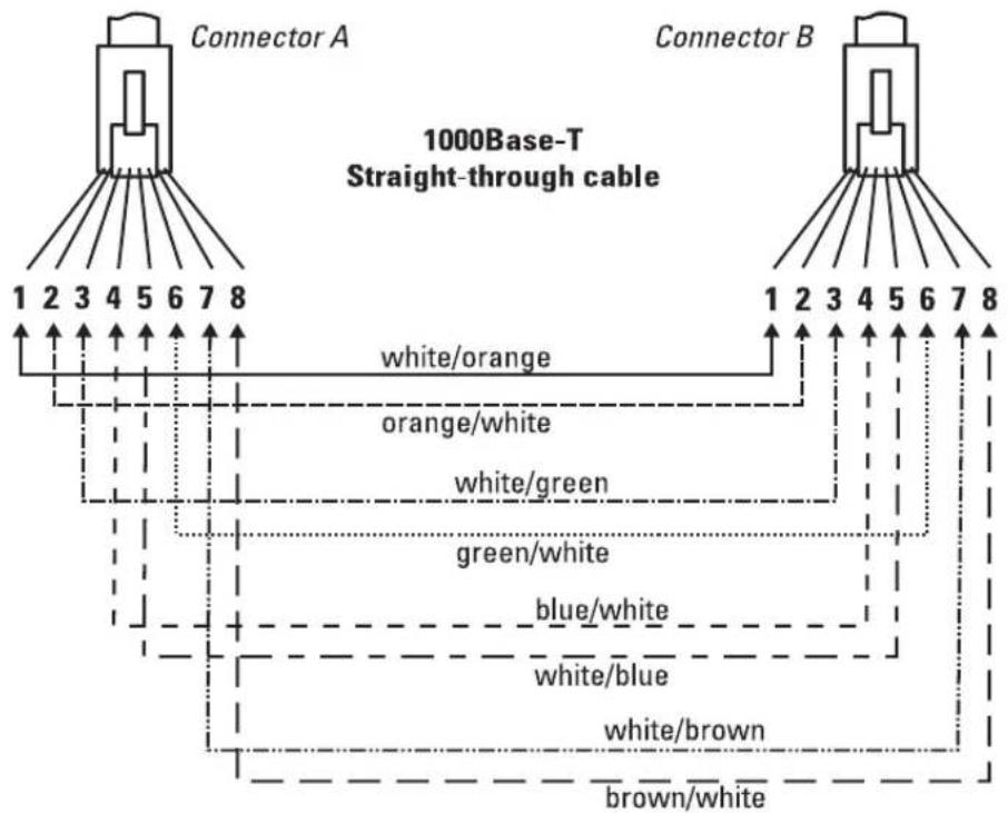
Note
Pins 1 and 2 on connector "A" must be wired as a twisted pair to pins 1 and 2 on connector "B".
Pins 3 and 6 on connector "A" must be wired as a twisted pair to pins 3 and 6 on connector "B".
Pins 4 and 5 on connector "A" must be wired as a twisted pair to pins 4 and 5 on connector "B".
Pins 7 and 8 on connector "A" must be wired as a twisted pair to pins 7 and 8 on connector "B".
Pin Assignments
For 1000Base-T operation, all four pairs of wires are used for both transmit and receive.
Safety and EMC Regulatory Statements
Safety Information

WARNING
Documentation reference symbol. If the product is marked with this symbol, refer to the product documentation to get more information about the product.
A WARNING in the manual denotes a hazard that can cause injury or death.
Caution A Caution in the manual denotes a hazard that can damage equipment.
Do not proceed beyond a WARNING or Caution notice until you have understood the hazardous conditions and have taken appropriate steps.
Grounding
These are safety class I products and have protective earthing terminals. There must be an uninterruptible safety earth ground from the main power source to the product's input wiring terminals, power cord, or supplied power cord set. Whenever it is likely that the protection has been impaired, disconnect the power cord until the ground has been restored.
For LAN cable grounding:
■If your LAN covers an area served by more than one power distribution system, be sure their safety grounds are securely interconnected.
■LAN cables may occasionally be subject to hazardous transient voltages (such as lightning or disturbances in the electrical utilities power grid). Handle exposed metal components of the network with Caution.
Servicing
There are no user-serviceable parts inside these products. Any servicing, adjustment, maintenance, or repair must be performed only by service-trained personnel.
These products do not have a power switch; they are powered on when the power cord is plugged in.
Safety Information (Japan)
安全性の考慮
安全記号

Japan Power Cord Warning
EMC Regulatory Statements
U.S.A.
FCC Class A
This equipment has been tested and found to comply with the limits for a Class A digital device, pursuant to Part 15 of the FCC Rules. These limits are designed to provide reasonable protection against interference when the equipment is operated in a commercial environment. This equipment generates, uses, and can radiate radio frequency energy and, if not installed and used in accordance with the instruction manual, may cause interference to radio communications. Operation of this equipment in a residential area may cause interference in which case the user will be required to correct the interference at his own expense.
Canada
This product complies with Class A Canadian EMC requirements.
Australia/New Zealand

This product complies with Australia/New Zealand EMC Class A requirements.
Japan
VCCI Class A
Regulatory Model Identification Number
For regulatory identification purposes, the ProCurve Switch 5300xl Series are assigned a Regulatory Model Number. The Regulatory Model Number for these switches is RSVLC-0202.
This regulatory number should not be confused with the marketing name (ProCurve Switch 5300xl Series), or product numbers (J4819A, J4848A, J4849B, J4850A)
European Community

invent
DECLARATION OF CONFORMITY
according to ISO/IEC 17050-1 and EN17050-1
Supplier's Name:
Hewlett-Packard Company
DOC#: RSVLC-0202-22Jan08
Supplier's Address: 8000 Foothills Blvd.
Roseville, CA 95747-5502
U.S.A.
declares, that the product
Product Name 2 : HP ProCurve Switch 5304xl, 5308xl, 5348xl (bundle)
conforms to the following Product Specifications and regulations:
EMC: Class A
EN 55022:1998 +A1:2001 +A2:2002
EN 55024:1998 +A1+A2
EN 61000-3-2:2000 +A2:2005
EN 61000-3-3:1995 +A1:2001
FCC CFR47 Part 15
Safety:
EN 60950-1:2001 / IEC 60950-1:2001
EN 60825-1:1994 +A1+A2 / IEC 60825-1:1993 +A2 Class 1
The device complies with part 15 of the FCC Rules. Operation is subject to the following two conditions: (1) this device may not cause harmful interference, and (2) this device must accept any interference received, including interference that may cause undesired operation.
The product herewith complies with the requirements of the Low Voltage Directive 2006/95/EC, the EMC Directive 2004/108/EC and carries the CE marking accordingly.
Additional Information:
1) This product is assigned a Regulatory Model Number which stays with the regulatory aspects of the design. The Regulatory Model Number is that main product identifier in the regulatory documentation and test reports, this number should not be confused with the marketing name or the product numbers.
2) This product was tested with HP branded products only.
Roseville, 22 January 2008
Mike Avery, Regulatory Engineering Mgr.
European Contact: Your local Hewlett-Packard Sales and Service Office or Hewlett-Packard GmbH, Department HQ-TRE. Herrenberger Straße 140. D-71034 Böblingen (FAX: +49-7031-14-3143)
Recycle Statements
Waste Electrical and Electronic Equipment (WEEE) Statements

Disposal of Waste Equipment by Users in Private Household in the European Union
This symbol on the product or on its packaging indicates that this product must not be disposed of with your other household waste. Instead, it is your responsibility to dispose of your waste equipment by handing it over to a designated collection point for the recycling of waste electrical and electronic equipment. The separate collection and recycling of your waste equipment at the time of disposal will help to conserve natural resources and ensure that it is recycled in a manner that protects human health and the environment. For more information about where you can drop off your waste equipment for recycling, please contact your local city office, your household waste disposal service or the shop where you purchased the product.

Waste Electrical and Electronic Equipment (WEEE) Statements
 | Laitteiden hävittäminen kotitalouksissa Euroopan unionin alueellaJos tuotteessa tai sen pakkauksessa on tämä merkki, tuotetta ei saa hävittää kotitalousjätteiden mukana. Tällöin hävitettävä laite on toimitettava sähkölaitteiden ja elektronisten laitteiden kierrätyspisteeseen. Hävitettävien laitteiden erillinen käsittely ja kierrätys auttavat säästämään luonnonvaroja ja varmistamaan, että laite kierrätetään tavalla, joka estää terveyshaitat ja suojelee luontoa. Lisätietoja paikoista, joihin hävitettävät laitteet voi toimittaa kierrätettäväksi, saa ottamalla yhteyttä jätehuoltoon tai liikkeeseen, josta tuote on ostettu. |
 | Élimination des appareils mis au rebut par les ménages dans l'Union européenneLe symbole apposé sur ce produit ou sur son emballage indique que ce produit ne doit pas être jeté avec les déchets ménagers ordinaires. Il est de votre responsabilité de mettre au rebut vos appareils en les déposant dans les centres de collecte publique désignés pour le recyclage des équipements électriques et électroniques. La collecte et le recyclage de vos appareils mis au rebut indépendamment du reste des déchets contribue à la préservation des ressources naturelles et garantit que ces appareils seront recyclés dans le respect de la santé humaine et de l'environnement. Pour obtenir plus d'informations sur les centres de collecte et de recyclage des appareils mis au rebut, veuillez contacter les autorités locales de votre région, les services de collecte des ordures ménagères ou le magasin dans lequel vous avez acheté ce produit. |
 | Entsorgung von Altgeräten aus privaten Haushalten in der EUDas Symbol auf dem Produkt oder seiner Verpackung weist darauf hin, dass das Produkt nicht über den normalen Hausmüll entsorgt werden darf. Benutzer sind verpflichtet, die Altgeräte an einer Rücknahmestelle für Elektro- und Elektronik-Altgeräte abzugeben. Die getrennte Sammlung und ordnungsgemäße Entsorgung Ihrer Altgeräte trägt zur Erhaltung der natürlichen Ressourcen bei und garantiert eine Wiederverwertung, die die Gesundheit des Menschen und die Umwelt schützt. Informationen dazu, wo Sie Rücknahmestellen für Ihre Altgeräte finden, erhalten Sie bei Ihrer Stadtverwaltung, den örtlichen Müllentsorgungsbetrieben oder im Geschäft, in dem Sie das Gerät erworben haben |
 | Απόρριψη άχρηστου εξοπλισμού από χρήστες σε ιδιωτικά νοικοκυριά στην Ευρωπαϊκή ΈνωσηΤο σύμβολο αυτό στο προϊόν ή τη συσκευασία του υποδεικνύει ότι το συγκεκριμένο προϊόν δεν πρέπει να διατίθεται μαζί με τα άλλα οικιακά σας απορρίμματα. Αντίθετα, είναι δική σας ευθύνη να απορρίψετε τον άχρηστο εξοπλισμό σας παραδίδοντάς τον σε καθορισμένο σημείο συλλογής για την ανακύκλωση άχρηστου ηλεκτρικού και ηλεκτρονικού εξοπλισμού. Η ξεχωριστή συλλογή και ανακύκλωση του άχρηστου εξοπλισμού σας κατά την απόρριψη θα συμβάλει στη διατήρηση των φυσικών πόρων και θα διασφαλίσει ότι η ανακύκλωση γίνεται με τρόπο του προστατεύει την ανθρώπινη υγεία και το περιβάλλον. Για περισσότερες πληροφορίες σχετικά με το πού μπορείτε να παραδώσετε τον άχρηστο εξοπλισμό σας για ανακύκλωση, επικοινωνήστε με το αρμόδιο τοπικό γραφείο, την τοπική υπηρεσία διάθεσης οικιακών απορριμμάτων ή το κατάστημα όπου αγοράσατε το προϊόν. |
  | Készülékek magánháztartásban történő selejtezése az Európai Unió területénA készüléken, illetve a készülék csomagolásán látható azonos szimbólum annak jelzésére szolgál, hogy a készülék a selejtezés során az egyéb háztartási hulladéktól eltérő módon kezelendő. A vásárló a hulladékká vált készüléket köteles a kijelölt gyűjtőhelyre szállítani az elektromos és elektronikai készülékek újrahasznosítása céljából. A hulladékká vált készülékek selejtezéskori begyűjtése és újrahasznosítása hozzájárul a természeti erőforrások megőrzéséhez, valamint biztosítja a selejtezett termékek környezetre és emberi egészségre nézve biztonságos feldolgozását.A begyűjtés pontos helyéről bővebb tájékoztatást a lakhelye szerint illetékes önkormányzattól, az illetékes szemételtakarító vállalattól, illetve a terméket elárusító helyen kaphat.Smaltimento delle apparecchiature da parte di privati nel territorio dell'Unione EuropeaQuesto simbolo presente sul prodotto o sulla sua confezione indica che il prodotto non può essere smaltito insieme ai rifiuti domestici. È responsabilità dell'utente smaltire le apparecchiature consegnandole presso un punto di raccolta designato al riciclo e allo smaltimento di apparecchiature elettriche ed elettroniche. La raccolta differenziata e il corretto riciclo delle apparecchiature da smaltire permette di proteggere la salute degli individui e l'ecosistema. Per ulteriori informazioni relative ai punti di raccolta delle apparecchiature, contattare l'ente locale per lo smaltimento dei rifiuti, oppure il negozio presso il quale è stato acquistato il prodotto. |
 | Nolietotu iekārtu iznīcināšanas noteikumi lietotājiem Eiropas Savienības privātajās mājsaimniecībāsŠāds simbols uz izstrādājuma vai uz tā iesaiņojuma norāda, ka šo izstrādājumu nedrīkst izmest kopā ar citiem sadzīves atkritumiem. Jūs atbildat par to, lai nolietotās iekārtas tiktu nodotas speciāli iekārtotos punktos, kas paredzēti izmantoto elektrisko un elektronisko iekārtu savākšanai otrreizējai pārstrādei. Atseviška nolietoto iekārtu savākšana un otrreizējā pārstrāde palīdzēs saglabāt dabas resursus un garantēs, ka šīs iekārtas tiks otrreizēji pārstrādātas tādā veidā, lai pasargātu vidi un cilvēku veselību. Lai uzzinātu, kur nolietotās iekārtas var izmest otrreizējai pārstrādei, jāvēršas savas dzīves vietas pašvaldībā, sadzīves atkritumu savākšanas dienestā vai veikalā, kurā izstrādājums tika nopirkts. |
 | Vartotojų iš privačių namų ūkių įrangos atliekų šalinimas Europos SajungojeŠis simbolis ant gaminio arba jo pakuotės rodo, kad šio gaminio šalinti kartu su kitomis namų ūkio atliekomis negalima. Šalintinas įrangos atliekas privalote pristatyti i specialią surinkimo vietą elektros ir elektroninės įrangos atliekoms perdirbti. Atskirai surenkamos ir perdirbamos šalintinos įrangos atliekos padės saugoti gamtinius išteklius ir užtikrinti, kad jos bus perdirbtos tokiu būdu, kuris nekenkia žmonių sveikatai ir aplinkai. Jeigu norite sužinoti daugiau apie tai, kur galima pristatyti perdirbtinas įrangos atliekas, kreipkitės i savo seniūniją, namų ūkio atliekų šalinimo tarnybą arba parduotuvę, kurioje įsigijote gaminį. |
 | Verwijdering van afgedankte apparatuur door privé-gebruikers in de Europese UnieDit symbool op het product of de verpakking geeft aan dat dit product niet mag worden gedeponeerd bij het normale huishoudelijke afval. U bent zelf verantwoordelijk voor het inleveren van uw afgedankte apparatuur bij een inzamelingspunt voor het recyclen van oude elektrische en elektronische apparatuur. Door uw oude apparatuur apart aan te bieden en te recyclen, kunnen natuurlijke bronnen worden behouden en kan het materiaal worden hergebruikt op een manier waarmee de volksgezondheid en het milieu worden beschermd. Neem contact op met uw gemeente, het afvalinzamelingsbedrijf of de winkel waar u het product hebt gekocht voor meer informatie over inzamelingspunten waar u oude apparatuur kunt aanbieden voor recycling. |
 | Pozbywanie się zużytego sprzętu przez użytkowników w prywatnych gospodarstwach domowych w Unii EuropejskiejTen symbol na produkcie lub jego opakowaniu oznacza, że produktu nie wolno wyrzucać do zwykłych pojemników na śmieci. Obowiązkiem użytkownika jest przekazanie zużytego sprzętu do wyznaczonego punktu zbiórki w celu recyklingu odpadów powstałych ze sprzętu elektrycznego i elektronicznego. Osobna zbiórka oraz recykling zużytego sprzętu pomogą w ochronie zasobów naturalnych i zapewnią ponowne wprowadzenie go do obiegu w sposób chroniący zdrowie człowieka i środowisko. Aby uzyskać więcej informacji o tym, gdzie można przekazać zużyty sprzęt do recyklingu, należy się skontaktować z urzędem miasta, zakładem gospodarki odpadami lub sklepem, w którym zakupiono produkt. |
Recycle Statements
Waste Electrical and Electronic Equipment (WEEE) Statements
 | Descarte de Lixo Elétrico na Comunidade EuropéiaEste símbolo encontrado no produto ou na embalagem indica que o produto não deve ser descartado no lixo doméstico comum. É responsabilidade do cliente descartar o material usado (lixo elétrico), encaminhando-o para um ponto de coleta para reciclagem. A coleta e a reciclagem seletivas desse tipo de lixo ajudarão a conservar as reservas naturais; sendo assim, a reciclagem será feita de uma forma segura, protegendo o ambiente e a saúde das pessoas. Para obter mais informações sobre locais que reciclam esse tipo de material, entre em contato com o escritório da HP em sua cidade, com o serviço de coleta de lixo ou com a loja em que o produto foi adquirido. |
 | Likvidácia vyradených zariadení v domácnostiach v Európskej úniiSymbol na výrobku alebo jeho balení označuje, že daný výrobok sa nesmie likvidovať s domovým odpadom. Povinnosťou spotrebitel'a je odovzdat' vyradené zariadenie v zbernom mieste, ktoré je určené na recykláciu vyradených elektrických a elektronických zariadení. Separovaný zber a recyklácia vyradených zariadení prispieva k ochrane prírodných zdrojov a zabezpečuje, že recyklácia sa vykonáva spôsobom chrániacim l'udské zdravie a životné prostredie. Informácie o zberných miestach na recykláciu vyradených zariadení vám poskytne miestne zastupitel'stvo, spoločnosť zabezpečujúca odvoz domového odpadu alebo obchod, v ktorom ste si výrobok zakúpili. |
 | Odstranjevanje odslužene opreme uporabnikov v zasebnih gospodinjstvih v Evropski unijiTa znak na izdelku ali njegovi embalaži pomeni, da izdelka ne smete odvreči med gospodinjske odpadke. Nasprotno, odsluženo opremo morate predati na zbirališče, pooblaščeno za recikliranje odslužene električne in elektronske opreme. Ločeno zbiranje in recikliranje odslužene opreme prispeva k ohranjanju naravnih virov in zagotavlja recikliranje te opreme na zdravju in okolju neškodljiv način. Za podrobnejše informacije o tem, kam lahko odpeljete odsluženo opremo na recikliranje, se obrnite na pristojni organ, komunalno službo ali trgovino, kjer ste izdelek kupili. |
 | Eliminación de residuos de equipos eléctricos y electrónicos por parte de usuarios particulares en la Unión EuropeaEste símbolo en el producto o en su envase indica que no debe eliminarse junto con los desperdicios generales de la casa. Es responsabilidad del usuario eliminar los residuos de este tipo depositándolos en un "punto limpio" para el reciclado de residuos eléctricos y electrónicos. La recogida y el reciclado selectivos de los residuos de aparatos eléctricos en el momento de su eliminación contribuirá a conservar los recursos naturales y a garantizar el reciclado de estos residuos de forma que se proteja el medio ambiente y la salud. Para obtener más información sobre los puntos de recogida de residuos eléctricos y electrónicos para reciclado, póngase en contacto con su ayuntamiento, con el servicio de eliminación de residuos domésticos o con el establecimiento en el que adquirió el producto. |
 | Bortskaffande av avfallsprodukter från användare i privathushåll inom Europeiska UnionenOm den här symbolen visas på produkten eller förpackningen betyder det att produkten inte får slängas på samma ställe som hushållssopor. I stället är det ditt ansvar att bortskaffa avfallet genom att överlämna det till ett uppsamlingsställe avsett för återvinning av avfall från elektriska och elektroniska produkter. Separat insamling och återvinning av avfallet hjälper till att spara på våra naturresurser och gör att avfallet återvinns på ett sätt som skyddar människors hälsa och miljön. Kontakta ditt lokala kommunkontor, din närmsta återvinningsstation för hushållsavfall eller affären där du köpte produkten för att få mer information om var du kan lämna ditt avfall för återvinning. |
Index
Symbols
! (attention) LED ... 1-7
Numerics
100/1000Base-T
connections, length limitations ... 2-6
note on cable requirements ... B-2
ports, cables used with ... 2-6, B-2
twisted-pair cable specifications ... B-2
1000Base-LH
connections, length limitations ... 2-6
ports, cables used with ... 2-6
1000Base-LX
connections, length limitations ... 2-6
ports, cables used with ... 2-6
1000Base-SX
connections, length limitations ... 2-6
ports, cables used with ... 2-6
100Base-TX
ports, cables used with ... B-2
twisted-pair cable specifications ... B-2
10Base-T
ports, cables used with ... B-2
twisted-pair cable specifications ... B-2
A
Act LED ... 1-6
aggregation switch, example topology as ... 2-25
auto MDI/MDI-X operation ... B-6, B-8
HP Auto-MDIX feature ... B-4
B
back of switch
description ... 1-9
power connector ... 1-9
slot for redundant power supply ... 1-9
basic connectivity, example topology ... 2-22
basic switch configuration
IP address ... 3-3
manager password ... 3-2
subnet mask ... 3-3
Switch Setup screen ... 3-2
Bootp
automatic switch configuration ... 3-2
for in-band console access ... 2-19
buttons
Clear button ... 1-8
LED Mode Select button ... 1-7
Reset button ... 1-8
C
cabinet
mounting the switch in ... 2-14
note on mounting screws ... 2-16
cables
100/1000Base-T
cable specifications ... B-2
connections ... 2-6
note on cable requirements ... B-2
1000Base-LH
connections ... 2-6
fiber-optic cable specifications ... B-3
1000Base-LX
connections ... 2-6
fiber-optic cable specifications ... B-3
1000Base-SX
connections ... 2-6
fiber-optic cable specifications ... B-3
100Base-TX
cable specifications ... B-2
10Base-T
cable specifications ... B-2
connecting cables to switch ports ... 2-18
effects of non-standard cables ... 4-1
fiber-optic, specifications ... B-3
infrastructure requirements ... 2-6
length limitations ... 2-6
required types ... 2-6
serial for direct console connection ... 2-20
cables, twisted pair
category 3, 4, 5 ... B-5
connector pin-outs ... B-4
crossover cable pin-out ... B-7
HP Auto-MDIX feature ... B-4
MDI-X to MDI connections ... B-6, B-8
MDI-X to MDI-X connections ... B-7
note on requirements for 1000Base-T ... B-2
pin-outs ... B-6, B-8
specifications ... B-2
straight-through cable pin-out ... B-6, B-8
switch-to-computer connection ... B-6, B-8
switch-to-switch or hub connection ... B-7
wiring rules ... B-5
cabling infrastructure ... 2-6
Clear button
deleting passwords ... 1-8
description ... 1-8
location on switch ... 1-4, 1-8
restoring factory default configuration ... 1-8, 4-12
to delete password protection ... 3-4
CLI prompt, console
displaying ... 2-20
configuration
checking when troubleshooting ... 4-3
DHCP/Bootp ... 3-2
IP address ... 3-3
IP address, manually ... 3-3
manager password ... 3-2
restoring factory defaults ... 1-8, 4-12
subnet mask ... 3-3
Switch Setup screen ... 3-2
connecting the switch to a power source ... 2-18
connector specifications ... A-2
console
checking messages during
troubleshooting ... 4-10
displaying the CLI prompt ... 2-20
features ... 2-19
how to connect in-band ... 2-19
how to connect out-of-band ... 2-19
serial cable connection ... 2-20
Switch Setup screen ... 3-2
telnet access ... 2-20, 3-5
terminal configuration ... 2-19
console port
description ... 1-8
location on switch ... 1-4
crossover cable
pin-out ... B-7
use with fixed port configurations ... B-5
D
deleting passwords ... 1-8
description
back of switches ... 1-9
front of switches ... 1-4
LEDs ... 1-5
DHCP
automatic switch configuration ... 3-2
for in-band console access ... 2-19
diagnostic tests ... 4-10
checking the console messages ... 4-10
checking the LEDs ... 4-4, 4-10
end-to-end connectivity ... 4-11
testing the switch only ... 4-10
testing twisted-pair cabling ... 4-11
downloading new code ... 4-13
E
edge switch, example topology as ... 2-23
electrical specifications ... A-1
EMC regulatory statements ... C-8
environmental specifications ... A-1
equipment cabinet
mounting the switch in ... 2-14
note on mounting screws ... 2-16
example network topologies ... 2-22
as an aggregation switch ... 2-25
as an edge switch ... 2-23
basic connectivity ... 2-22
F
factory default configuration, restoring ... 1-8, 4-12
Fan Status LED ... 1-5
showing error conditions ... 4-4
Fault LED
behavior during self test ... 2-13
description ... 1-5
flashing definition ... 1-6
location on switch ... 1-4
showing error conditions ... 4-4
FDx LED ... 1-6
features
console ... 2-19
Switch 5300XL Series ... 1-10
fiber-optic cables ... B-3
1000Base-LH ... B-3
1000Base-LX ... B-3
1000Base-SX ... B-3
flashing LEDs
error indications ... 4-4
front of switch
Clear button ... 1-8
console port ... 1-8
description ... 1-4
LEDs ... 1-5
Mode Select button and indicator LEDs ... 1-7
Reset button ... 1-8
full-duplex fixed configuration
effects on network connections ... 4-2
G
Gigabit-LH
ports, cables used with ... B-3
Gigabit-LX
ports, cables used with ... B-3
Gigabit-SX
ports, cables used with ... B-3
H
horizontal surface, mounting switch on ... 2-16
hot swap
mini-GBICs ... 1-11
modules ... 1-11
transceivers ... 1-11
hot swapping
redundant power supply ... 1-9, 2-10
resetting the switch for new module type ... 2-21
switch modules ... 2-21
HP Auto-MDIX
feature description ... B-4
I
in-band
console access, types of ... 2-19
managing the switch ... 3-1
included parts ... 2-1
installation
connecting the switch to a power source ... 2-18
horizontal surface mounting ... 2-16
network cable requirements ... 2-6
optional modules ... 2-8
precautions ... 2-4, 2-5
rack or cabinet mounting ... 2-14
redundant power supply ... 2-10
Series 53100XL Switches ... 2-1
site preparation ... 2-6
summary of steps ... 2-3
wall mounting ... 2-17
IP address
configuring ... 3-3
using for switch management ... 3-5
L
LED Mode Select
button ... 1-7
indicator LEDs ... 1-6, 1-7
LEDs
!(attention) ... 1-7
Act ... 1-6
behavior during self test ... 2-13
checking during troubleshooting ... 4-10
descriptions of ... 1-5
error indications ... 4-4
Fan Status ... 1-5
showing error conditions ... 4-4
Fault ... 1-5
behavior during self test ... 2-13
showing error conditions ... 4-4
FDx ... 1-6
flashing definition ... 1-6
Link ... 1-6
Max ... 1-6
Mode
description ... 1-6
selecting the display ... 1-7
mode select indicators ... 1-6
Module Status ... 1-6
showing error conditions ... 4-4
on switch chassis ... 1-5
on switch modules ... 1-6
Power ... 1-5
behavior during error conditions ... 4-4
behavior during self test ... 2-13
Power Status ... 1-5
behavior during self test ... 2-13
showing error conditions ... 4-4
Self Test ... 1-5
behavior during self test ... 2-13
showing error conditions ... 4-4
length limitations
100/1000Base-T connections ... 2-6
1000Base-LH connections ... 2-6
1000Base-LX connections ... 2-6
1000Base-SX connections ... 2-6
Link LEDs ... 1-6
link test ... 4-11
M
Max LED ... 1-6
MDI-X to MDI network cable ... B-6, B-8
MDI-X to MDI-X network cable ... B-7
mini-GBICs
hot swap feature ... 1-11
indications of unsupported ... 4-7
supported types ... 1-10
Mode LEDs
description ... 1-6
selecting the display ... 1-7
module slots
location on switch ... 1-4
Module Status LEDs ... 1-6
showing error conditions ... 4-4
modules, switch
hot swapping ... 2-21
installing ... 2-8
LEDs ... 1-6
list of available types ... 1-10
mounting the switch
in a rack or cabinet ... 2-14
precautions ... 2-4, 2-5
on a horizontal surface ... 2-16
on a wall ... 2-17
precautions ... 2-17
N
network cables
100/1000Base-T
connections ... 2-6
1000Base-LH connections ... 2-6
1000Base-LX connections ... 2-6
1000Base-SX connections ... 2-6
fiber-optic, specifications ... B-3
HP Auto-MDIX feature ... B-4
required types ... 2-6
twisted-pair connector pin-outs ... B-4
twisted-pair, specifications ... B-2
twisted-pair, wiring rules ... B-5
network devices
connecting to the switch ... 2-18
network ports
connecting to ... 2-18
LEDs for ... 1-6
standards compliance ... A-2
types of ... 2-6
network topologies, examples of ... 2-22
non-standard network cables, effects ... 4-1
0
out-of-band console access ... 2-19, 3-5
P
parts included with the switch ... 2-1
passwords
configuring ... 3-2
deleting ... 1-8
deleting with the Clear button ... 3-4
if you lose the password ... 3-4
physical specifications, switch ... A-1
Ping test ... 4-11
pin-outs, twisted-pair cables ... B-4
port configuration
checking when troubleshooting ... 4-3
port LEDs
Link ... 1-6
Mode ... 1-6
ports
console ... 2-19
HP Auto-MDIX feature ... B-4
network connections ... 2-18
power connector ... 1-9
Power LED
behavior during error conditions ... 4-4
behavior during self test ... 2-13
description ... 1-5
location on switch ... 1-4
Power Status LEDs ... 1-5
behavior during self test ... 2-13
showing error conditions ... 4-4
power supply
connecting to a power source ... 2-18
installation cautions ... 1-9, 2-10
making redundant power connections ... 2-18
precautions
installing power supply ... 1-9, 2-10
mounting the switch in a rack or cabinet ... 2-4, 2-5
mounting the switch on a wall ... 2-17
power requirements ... 2-4, 2-5
preparing the installation site ... 2-6
Proactive Network tools
diagnostics with ... 4-9
R
rack
mounting the switch in ... 2-14
rebooting the switch
to initialize changed module type ... 2-8
recycle statements ... D-1
redundant power connections ... 2-18
redundant power supply
installation cautions ... 1-9, 2-10
installing ... 2-10
slot for installing ... 1-9
regulatory statements ... C-8
Reset button
description ... 1-8
location on switch ... 1-4, 1-8
restoring factory default configuration ... 4-12
resetting the switch
factory default reset ... 4-12
for module hot swap ... 2-21
location of Reset button ... 1-8
troubleshooting procedure ... 4-10
routing features ... 1-11
S
safety and regulatory statements ... C-1
safety specifications ... A-2
selecting the Mode LED display ... 1-7
self test
Fault LED behavior ... 2-13
LED behavior during ... 2-13
Power LED behavior ... 2-13
Self Test LED behavior ... 2-13
Self Test LED
behavior during factory default reset ... 4-12
behavior during self test ... 2-13
description ... 1-5
showing error conditions ... 4-4
serial cable
for direct console connection ... 2-20
slots for modules
location on switch ... 1-4
specifications
connectors ... A-2
electrical ... A-1
environmental ... A-1
physical ... A-1
safety ... A-2
straight-through cable
pin-out ... B-6, B-8
use with fixed port configurations ... B-5
subnet mask, configuring ... 3-3
summary
of cables used with the switch ... 2-6
of switch installation ... 2-3
supported mini-GBICs ... 1-10
supported transceivers ... 1-10
switch
connecting to a power source ... 2-18
description ... 1-1
electrical specifications ... A-1
environmental specifications ... A-1
features ... 1-10
front panel description ... 1-4
included parts ... 2-1
mounting in a rack or cabinet ... 2-14
mounting on a horizontal surface ... 2-16
mounting on a wall ... 2-17
physical specifications ... A-1
switch chassis
LED descriptions ... 1-5
switch modules
booting the switch to initialize changed module type ... 2-8
hot swapping ... 2-21
installing ... 2-8
LEDs descriptions ... 1-6
list of available types ... 1-10
switch operation
verifying after installation ... 2-12
Switch Setup screen ... 3-2
configuring a subnet mask ... 3-3
configuring an IP address ... 3-3
field descriptions ... 3-3
T
telnet access to the console ... 2-20, 3-5
terminal configuration ... 2-19
testing
checking the console messages ... 4-10
checking the LEDs ... 4-10
diagnostic tests ... 4-10
end-to-end communications ... 4-11
link test ... 4-11
Ping test ... 4-11
switch operation ... 4-10
switch-to-device communications ... 4-11
twisted-pair cabling ... 4-11
tips for troubleshooting ... 4-1
topologies
effects of improper topology ... 4-2
examples of ... 2-22
as an aggregation switch ... 2-25
as an edge switch ... 2-23
basic connectivity ... 2-22
tranceivers
hot swap feature ... 1-11
transceivers
supported types ... 1-10
troubleshooting ... 4-1
basic tips ... 4-1
checking port configuration ... 4-3
checking the console messages ... 4-10
checking the LEDs ... 4-10
common network problems ... 4-1
connecting to fixed full-duplex devices ... 4-2
diagnostic tests ... 4-10
effects of improper topology ... 4-2
effects of non-standard cables ... 4-1
link test ... 4-11
Ping test ... 4-11
Proactive Network tools ... 4-9
restoring factory default configuration ... 4-12
testing connections to other devices ... 4-11
testing end-to-end communications ... 4-11
testing the switch ... 4-10
testing the twisted-pair cables ... 4-11
twisted-pair cable ... B-2
crossover cable pin-out ... B-7
pin-outs ... B-4, B-6, B-8
straight-through cable pin-out ... B-6, B-8
switch-to-computer connection ... B-6, B-8
switch-to-switch or hub connection ... B-7
testing ... 4-11
twisted-pair ports
HP Auto-MDIX feature ... B-4
V
VT-100 terminal
serial cable connection for ... 2-20
W
wall
mounting switch on ... 2-17
wiring rules for twisted-pair cables ... B-5
ProCurve
Networking by HP
© Copyright 2001, 2005 - 2007 Hewlett-Packard Development Company, L.P.
Printed In Singapore
December 2007
Manual Part Number
5991-8597


- PROCURVE SERIES 5300XL SWITCHES
- PUBLICATION NUMBER
- APPLICABLE PRODUCTS
- DISCLAIMER
- WARRANTY
- SAFETY
- CONTENTS
- INTRODUCING THE PROCURVE SWITCH 5300XL SERIES
- INSTALLING THE SWITCH 5300XL SERIES
- GETTING STARTED WITH SWITCH CONFIGURATION
- TROUBLESHOOTING
- A SPECIFICATIONS
- B SWITCH PORTS AND NETWORK CABLES
- CROSSOVER TWISTED-PAIR CABLE FOR
- STRAIGHT-THROUGH TWISTED-PAIR CABLE FOR
- C SAFETY AND EMC REGULATORY STATEMENTS
- D RECYCLE STATEMENTS
- INDEX
- FRONT OF THE SWITCH
- LEDS
- LED MODE SELECT BUTTON AND INDICATOR LEDS
- CONSOLE PORT
- RESET BUTTON
- CLEAR BUTTON
- BACK OF THE SWITCH
- POWER CONNECTOR
- SLOT FOR REDUNDANT POWER SUPPLY
- CAUTION
- SWITCH FEATURES
- INCLUDED PARTS
- JAPAN POWER CORD WARNING
- INSTALLATION PROCEDURES
- SUMMARY
- INSTALLATION PRECAUTIONS (CONTINUED)
- CAUTIONS
- PREPARE THE INSTALLATION SITE
- CABLING INFRASTRUCTURE
- INSTALLATION LOCATION
- INSTALL SWITCH XL MODULES
- MODULE INSTALLATION NOTES
- (OPTIONAL) INSTALL SECOND POWER SUPPLY
- VERIFY THE SWITCH PASSES SELF TEST
- LED BEHAVIOR
- DURING THE SELF TEST
- WHEN THE SELF TEST COMPLETES SUCCESSFULLY
- MOUNT THE SWITCH
- RACK OR CABINET MOUNTING
- EQUIPMENT CABINET NOTE
- HORIZONTAL SURFACE MOUNTING
- NOTE
- WALL MOUNTING
- CONNECT THE SWITCH TO A POWER SOURCE
- CONNECT THE NETWORK DEVICES
- CONDITION DIAGNOSTIC TIP
- PORT LED IS STILL OFF WHEN A CABLE IS CONNECTED
- (OPTIONAL) CONNECT A CONSOLE TO THE SWITCH
- TERMINAL CONFIGURATION
- DIRECT CONSOLE ACCESS
- TELNET CONSOLE ACCESS
- HOT SWAPPING SWITCH MODULES
- ADDING OR REPLACING MODULES
- CHANGING THE MODULE TYPE
- EXAMPLE NETWORK TOPOLOGIES
- BASIC CONNECTIVITY
- RECOMMENDED MINIMAL CONFIGURATION
- USING THE SWITCH SETUP SCREEN
- PROCURVE SWITCH 5308XL
- WHERE TO GO FROM HERE
- USING THE IP ADDRESS FOR REMOTE SWITCH MANAGEMENT
- STARTING A TELNET SESSION
- STARTING A WEB BROWSER SESSION
- CONFIGURING THE PROCURVE ACCESS CONTROLLER XL MODULE (J8162A)
- WL/760WL CONFIGURATION
- MODULE CONFIGURATION
- PROCURVE SWITCH 5308XL (CONFIG)
- ACCESS-CONTROL-SERVER IP SECRET
- ACCESS-CONTROL-SERVER IP 13.13.13.8 SECRET 77340H 77340H
- SHOW STATUS
- XL SWITCH CONFIGURATION
- PROCURVE SWITCH 5308XL (CONFIG) # VLAN
- PROCURVE SWITCH 5308XL (CONFIG) (VLAN ) # UNTAGGED UP
- PROCURVE SWITCH 5308XL (CONFIG) # ACCESS-CONTROLLER
- SHOW VLANS
- CONFIGURING THE PROCURVE WIRELESS EDGE SERVICES XL MODULES (J9001A, J9003A)
- CONFIGURING AN IP ADDRESS FOR THE MODULE
- PROCURVE (CONFIG)# WIRELESS-SERVICES
- PROCURVE# CONFIGURE
- PROCURVE(WIRELESS-SERVICES-) (CONFIG-IF)# IP ADDRESS
- PROCURVE(WIRELESS-SERVICES-B)#CONFIGURE
- PROCURVE(WIRELESS-SERVICES-B)(CONFIG)#IP DEFAULT-GATEWAY
- CONFIGURING VLANS ON THE 5300XL SWITCH
- DETERMINING A MODULE CONFIGURATION BACKUP PROCESS
- CONFIGURING WIRELESS LAN SERVICES
- BASIC TROUBLESHOOTING TIPS
- CONNECTING TO DEVICES THAT HAVE A FIXED FULL-DUPLEX CONFIGURATION
- DIAGNOSING WITH THE LEDS
- PROACTIVE NETWORKING
- HARDWARE DIAGNOSTIC TESTS
- TESTING THE SWITCH BY RESETTING IT
- CHECKING THE SWITCH LEDS
- CHECKING CONSOLE MESSAGES
- TESTING TWISTED-PAIR CABLING
- TESTING SWITCH-TO-DEVICE NETWORK COMMUNICATIONS
- TESTING END-TO-END NETWORK COMMUNICATIONS
- RESTORING THE FACTORY DEFAULT CONFIGURATION
- DOWNLOADING NEW CODE
- HP CUSTOMER SUPPORT SERVICES
- BEFORE CALLING SUPPORT
- INFORMATION ITEM INFORMATION LOCATION
- PHYSICAL
- HEIGHT
- WEIGHT
- ELECTRICAL
- ENVIRONMENTAL
- ACOUSTIC
- NETWORK CONNECTORS
- SWITCH PORTS AND NETWORK CABLES
- SWITCH PORTS
- TWISTED PAIR
- FIBER-OPTIC
- CABLES
- TWISTED-PAIR
- TWISTED-PAIR CABLE/CONNECTOR PIN-OUTS
- OTHER WIRING RULES
- STRAIGHT-THROUGH TWISTED-PAIR CABLE FOR 10 MBPS OR 100 MBPS NETWORK CONNECTIONS
- PIN ASSIGNMENTS
- CROSSOVER TWISTED-PAIR CABLE FOR 10 MBPS OR 100 MBPS NETWORK CONNECTION
- STRAIGHT-THROUGH TWISTED-PAIR CABLE FOR 1000 MBPS NETWORK CONNECTIONS
- SAFETY AND EMC REGULATORY STATEMENTS
- SAFETY INFORMATION
- WARNING
- GROUNDING
- SERVICING
- SAFETY INFORMATION (JAPAN)
- EMC REGULATORY STATEMENTS
- CANADA
- AUSTRALIA/NEW ZEALAND
- JAPAN
- REGULATORY MODEL IDENTIFICATION NUMBER
- EUROPEAN COMMUNITY
- DECLARATION OF CONFORMITY
- ADDITIONAL INFORMATION
- RECYCLE STATEMENTS
- WASTE ELECTRICAL AND ELECTRONIC EQUIPMENT (WEEE) STATEMENTS
- DISPOSAL OF WASTE EQUIPMENT BY USERS IN PRIVATE HOUSEHOLD IN THE EUROPEAN UNION
- SYMBOLS
- NUMERICS
- A
- B
- C
- D
- E
- F
- G
- H
- I
- L
- M
- N
- P
- POWER LED
- POWER STATUS LEDS
- POWER SUPPLY
- PRECAUTIONS
- PREPARING THE INSTALLATION SITE
- PROACTIVE NETWORK TOOLS
- R
- RACK
- REBOOTING THE SWITCH
- RECYCLE STATEMENTS ... D
- REDUNDANT POWER CONNECTIONS
- REDUNDANT POWER SUPPLY
- REGULATORY STATEMENTS ... C
- RESETTING THE SWITCH
- ROUTING FEATURES
- S
- SELF TEST
- SELF TEST LED
- SERIAL CABLE
- SLOTS FOR MODULES
- SPECIFICATIONS
- STRAIGHT-THROUGH CABLE
- SUBNET MASK, CONFIGURING
- SUPPORTED MINI-GBICS
- SUPPORTED TRANSCEIVERS
- SWITCH
- SWITCH CHASSIS
- T
- V
- W
- PROCURVE
Brand : HP
Model : ProCurve 5300xl
Category : Switch