
SB 8.8 - Uncategorized Solid State Logic - Free user manual and instructions
Find the device manual for free SB 8.8 Solid State Logic in PDF.


| Product Type | Stagebox I/O for SSL Live systems |
| Brand | Solid State Logic |
| Model | SB 8.8 |
| Inputs | 8 x mic/line inputs on XLR-1/4" combo jacks |
| Outputs | 8 x line outputs on XLR connectors |
| Connection | SSL Blacklight optical MADI with redundant link |
| Sample Rates | 48 kHz / 96 kHz |
| Digital Resolution | 24-bit A/D and D/A conversion |
| Frequency Response | 20 Hz - 20 kHz +/-0.5 dB |
| Dynamic Range | 112 dB (A-weighted) D/A |
| THD+N | < 0.002% at +24 dBu, 1 kHz |
| Mic Preamplifier Gain | 0 dB to +65 dB in 1 dB steps |
| Phantom Power | 48 V per input, switchable |
| Redundancy | Dual Blacklight ports for automatic failover |
| Power Supply | Dual internal 90-264 V AC universal supplies |
| Dimensions (W x H x D) | 19" x 2U x 300 mm |
| Weight | 5.5 kg / 12.1 lbs |
| Mounting | 19" rack mount with included ears |
| Cooling | Fanless, convection-cooled chassis |
| Operating Temperature | 0 °C to 40 °C (32 °F to 104 °F) |
| Maintenance | Wipe with dry cloth; no internal user-serviceable parts |
| Safety | Complies with CE and FCC; earth-connected power inlet |
| Repairability | Modular design; replaceable PSU and I/O cards by qualified technicians |
Frequently Asked Questions - SB 8.8 Solid State Logic
User questions about SB 8.8 Solid State Logic
0 question about this device. Answer the ones you know or ask your own.
Ask a new question about this device
Download the instructions for your Uncategorized in PDF format for free! Find your manual SB 8.8 - Solid State Logic and take your electronic device back in hand. On this page are published all the documents necessary for the use of your device. SB 8.8 by Solid State Logic.
USER MANUAL SB 8.8 Solid State Logic
All rights reserved under International and Pan-American Copyright Conventions
SSL®, Solid State Logic®, Total Recall®, Gravity® and Tempest® are ® registered trademarks of Solid State Logic.
System T™, Live L100™, Live L200™, Live L300™, Live L500™, L500 Plus™, Blacklight™ are ™ trademarks of Solid State Logic.
Dante TM and Audinate TM are trademarks of Audinate Pty Ltd.
All other product names and trademarks are the property of their respective owners and are hereby acknowledged.
No part of this publication may be reproduced in any form or by any means, whether mechanical or electronic, without the written permission of Solid State Logic, Oxford, OX5 1RU, England.
As research and development is a continual process, Solid State Logic reserves the right to change the features and specifications described herein without notice or obligation.
Solid State Logic cannot be held responsible for any loss or damage arising directly or indirectly from any error or omission in this manual.
PLEASE READ ALL INSTRUCTIONS, PAY SPECIAL HEED TO SAFETY WARNINGS.
E&OE
December 2018
Document Revision History
| INITIAL RELEASE | Revision 1.0 | August 2015 |
| SECOND RELEASE | Format revision | 20th December 2018 |
Table of Contents
Introduction 4
Overview 4
Key Features 4
SB i16 and SB 8.8 Front Panel 4
SB i16 and SB 8.8 Rear Panel 4
Status LEDs and User Buttons 5
Channel LEDs 5
Device Reset 5
Brooklyn Reset 5
Hardware Connections 6
Mains Power Connections 6
Dante Connections 6
Audio Inputs and Outputs 6
GPIO 6
SSL Network I/O Controller 7
Installing Network I/O Controller 7
Network Configuration - PC 7
Network Configuration - Device 7
The GUI 8
Network View 8
Inputs/Outputs 9
Inputs 9
Focus Window 9
Outputs 10
GPIO 10
Setup 11
Ownership 12
Stagebox and Input Ownership 12
Individual Input Ownership 13
GPO Ownership 13
Gain Compensation 14
Compensated Ports 14
Calibration Point 15
Recalibrate Indication 15
Pad 16
Traditional 16
AutoPad 17
Dante Controller 18
Network Config 18
Device Info 18
Appendix A - General Specifications 19
Ventilation 19
Appendix B - Connector Pin Outs 20
XLR Wiring 20
D-Type Multipin Wiring 20
GPIO 21
Appendix C -
Performance Specifications 22
Mic/Line Inputs 22
Line Outputs 23
Appendix D - Safety Notices 24
General Safety 24
Installation Notes 24
Power Safety 25
For EU 25
Environmental Declaration 26
RoHS Notice 26
For USA 26
Electromagnetic Compatibility 26
Environmental 26
Introduction
Overview
SB i16 and SB 8.8 are, respectively, 2U, 16 input and 8 input/8 output SuperAnalogue™ Dante stageboxes, for all high-quality AoIP applications.
SB i16 and SB 8.8 can be controlled remotely from SSL Live and System T consoles as well as from SSL's Network I/O Controller app for PC.
SB i16 and 8.8 are ideally suited to studio and stage, featuring redundant power, redundant ruggedized etherCON Dante connections plus four GPIOs.
Key Features
- Interface between studio/stage/recording area and IP audio networks using Dante and AES67
- Redundant PSUs and Dante network connections
- 8 or 16 SSL SuperAnalogue Studio Grade preamps
- GPIO connectivity - embed tallies across the network
- Redundant network extension ports
- Clear front panel indication - signal present, phantom power, channel attention
- Gain-compensated inputs available to Dante network
- Device and parameter ownership assignment to avoid control conflicts
- AutoPad - automatically adjusts gain and pad settings to accommodate widest possible range of input signals
- Two-speed ball-bearing fan cooling - sufficiently quiet to place on a studio floor
SB i16 and SB 8.8 Front Panel

SB i16 and SB 8.8 Rear Panel

Status LEDs and User Buttons
![graph TD A["NET I/O SB 8.8"] --> B["RUN"] A --> C["PSU"] A --> D["STATUS"] A --> E["ATT"] A --> F["HOLD"] A --> G["Green - normal operation, both power supplies active"] A --> H["Red - primary or secondary power supply inactive"] A --> I["Green - normal operation"] A --> J["Red - indicates a fault h…](/content/2026/07/1553230/images/77ee2b8c82ed2f1a70a1963c0fe49a5ca1fa214157255e095cc550a4205064d6.jpg)
Channel LEDs

Device Reset
Performing a device reset will clear the SSL device settings. This includes ownership, input and GPIO states. This does not clear Dante Brooklyn card settings.
Brooklyn Reset
Resetting the Dante Brooklyn card to default settings is performed from Dante Controller. Under the 'Device Config' tab for a device select 'Clear Config'. This clears the device name, channel labels, IP address settings, sample rate, latency and existing audio routes. This does not clear SSL Ownership settings.
Hardware Connections
Mains Power Connections
SB i16 and SB 8.8 include redundant PSUs with IEC C14 inlets. Either supply can individually power the unit. Ideally these should be connected to separate power circuits to provide redundancy of incoming AC power.

Dante Connections

SB i16 and SB 8.8 have two redundant sets of network connections.
In Dante Controller it is possible to set Dante ports to switched mode rather than redundant mode. While this is possible, there is no need to here as the extension ports provide this functionality without loss of redundancy.
Never connect Primary and Secondary ports to the same single Dante network.
Audio Inputs and Outputs
Electronically balanced mic/line inputs and line outputs on latching XLR-3 connectors.

See Appendix B for pinout information.
GPIO
4 General Purpose opto-coupled inputs and 4 General Purpose relay outputs allow embedding and de-embedding of logic signals across the network.
See Appendix B for pinout information.

SSL Network I/O Controller
Installing Network I/O Controller
When an SB i16 or SB 8.8 is used without an SSL console, configuration and control is achieved using the SSL Network I/O Controller PC application. This can be downloaded from the SSL website as part of the Network I/O Stagebox upgrade package or as a standalone installer.
Locate and run the Network I/O Controller installer and follow the on-screen prompts to install the application.
Network Configuration - PC
Once Network I/O Controller is installed, connect the Windows PC to the same subnet as the Network I/O. The SSL Network I/O Controller application uses the network adapters configured in Dante Controller for communication. Before starting Network I/O Controller first open Dante Controller and select the network adaptors connected to the Dante network. 'Use shared Dante interface' must be selected to ensure all applications using the Dante network use the correct adaptors. Subsequent changes to network settings may require Network I/O Controller to be restarted.

TCP/IP is used to communicate with the unit, so check Windows firewall settings if communications are not working.
Set the computer to 'Never Sleep' to maintain communication.
Network Configuration - Device
Unless shipped as part of a preconfigured system, Network I/O units are set to obtain an IP address automatically.
If the IP settings need to be changed to a fixed address – to match the network environment in which the unit is to be installed – this can be achieved using the Dante Controller application.
Remember that the computer's network adapter configuration will also need to be updated to match the Network I/O.
For additional information see the Dante Controller section.
The GUI
The application window is divided into six sections:
Network View shows each SSL device on the Dante network. Input meters are shown for every analogue input. Clicking a device brings its parameters into the Detail View. Large arrows on the far left and right scroll for more devices.
Detail View shows channel details for the selected device. Large arrows on the far left and right scroll for more channels.
Focus View shows an expanded view of the selected channel.

5.202-064

GPIO View shows the active status for each GPI and GPO.
Page Select selects the detail view to show inputs, outputs, or setup options for each device.
Navigation switches the in-focus channel and allows for gain adjustment. These arrows are also mapped to the PC keyboard. Control toggles fine (0.1 dB) gain adjustment and Alt coarse (3 dB) gain adjustment.
Network View
Device
Name is set by the Dante Controller application.
Selected
device is highlighted with a cyan background.
A Red Highlight indicates a device that requires operator action:
• A flashing red background indicates a device with a clipping audio channel
- A solid red border highlights a device with an active Attention flag. If the device requiring attention is not already visible in the Network View window, then the appropriate large scroll arrow will show red to direct you to the appropriate device.

Att and Mute tallies show the status of these functions for every stagebox channel.
The Level Meter shows the real-time signal level for all analogue input channels. A red clipping indicator is also provided.
Greyed out devices marked Offline are 'known' to the network but uncontactable, typically switched off.
PSU Tallies
show the status of PSUs 1 and 2 for each stagebox.
Inputs/Outputs
Select the Inputs or Outputs tab in the Page Select area to view I/O available on the network.
Inputs

Focus Window

Outputs

GPIO
The SB i16 and SB 8.8 are equipped with 4 GP input and 4 GP output circuits. Inputs are opto-isolated voltage triggered and output closures are via DIL relay.
See Appendix B for connector pinout and contact ratings.

Setup
Press Setup in the Page Select area to display the system configuration information.
Stagebox Ownership and Inputs Ownership settings are detailed under Ownership.
![graph TD A["Name shows the device name as set in Dante Controller."] --> B["S300 dBu8"] C["Info shows the status of the device's redundant power supplies, fans, and temperature. Red indicates a fault."] --> B D["Operating Level allows selection of the maximum analogue I/O level in dBu (at 0dBFS) for…](/content/2026/07/1553230/images/12af86093c54998954ca3611457cf2a7a8ac3dc56aaea0c1f84ea29e7af1c002.jpg)
Ownership
Ownership offers a level of protection to inputs: when an input is owned by a console the input parameters can only be modified by the device that owns it. This prevents control conflicts between networked consoles and control computers sharing resources. Parameters covered by ownership are:
- Mic gain
- Mic/line switching
- Pad
- Input mute
- Audition
- Limiter
Note that multiple consoles can share the same input signal but only one device can control the input parameters. Altering the input settings will affect all consoles using the input.
Any System T console, SSL Live console or instance of the SSL Network I/O Controller PC application can control ownership. There are three levels of ownership:
- Stagebox ownership: control SB i16 and SB 8.8 setup information only
- Input ownership: control input parameters only
- Input x ownership: control of input parameters on a per input basis
N.B. Ownership settings are stored on the SB i16 and SB 8.8. The mute state is stored in volatile memory on the unit and all channels will reset to unmuted if the unit is repowered.
Stagebox and Input Ownership

Individual Input Ownership
One of three options will be displayed when an input is selected on a device, depending on the current ownership state. These options are Own, Take and Release:

When an SSL console makes routes from Stagebox inputs, the console will automatically become the owner of any unowned inputs. If an input is owned by a different controller then routing will not automatically take ownership, Take ownership will need to be performed if input control is required on this device. Ownership from Network I/O Controller is manually controlled.
Note that the audio route will still be made regardless of whether ownership is assigned.
GPO Ownership
The four GPO connections also have ownership status. The available ownership states are identical to those for stagebox inputs.

Gain Compensation
Each stagebox mic/line input has two transmit channels that can be subscribed to from the Dante network. Main channels follow the mic gain as set by the controller. Compensated channels nullify mic gain changes by applying a digital trim offset which is the negative equivalent of any analogue gain changes. Using Compensated channels ensures that devices receiving signals from the same stagebox avoid unintended changes to input source levels.
Compensated Ports
When connected to an SSL console or the Network I/O Controller app the main and compensated channels show as two separate devices.

The compensated output's level is controlled in the stagebox itself, so any Dante device can receive the compensated signal, it does not have to be an SSL console. The compensated channels for an SB 8.8 or SB i16 can be found in Dante Controller under the Transmit tab of the Routing Matrix or Device View, listed immediately after the main channels.

Calibration Point
The Calibration point is the value at which the analogue gain equals a digital trim value of 0 dB, i.e. there is no digital trim applied. Digital trim will be applied when the analogue gain level is above or below the Calibration point.

Recalibrate Indication

Pad
The SB i16 and SB 8.8 have two pad modes, Traditional and AutoPad. The pad mode is selected per stagebox (applied to all inputs) from the SETUP tab of the stagebox within Network I/O Controller.
![graph LR A["AutoPad is highlighted blue when active"] --> B["PAD MODE"] B --> C["AutoPad"]](/content/2026/07/1553230/images/fc2bacdf7a6d3e9565e5e2b460979c0aaff0d6dcfd9017d235e9dc5ffdeca043.jpg)
Traditional
Traditional pad mode is active when AutoPad is deselected. This allows the 20 dB pad to be inserted/removed manually. Inserting the pad will reduce the input gain by 20 dB. The reduced value will be shown in the input channel strip and the range of available gain values will be updated to reflect the pad state. Note that maximum and minimum gain values are dependant on the Operating Level setting.

Compensated channels will change signal level in accordance with the pad setting on the associated main channel when in traditional pad mode. If the pad is inserted on a main channel the signal level of both the main and compensated channel will drop by 20 dB.
AutoPad
AutoPad provides the entire possible gain range to the operator and silently applies the pad when the gain range is set to a low value that requires the pad to achieve.

When AutoPad is active the Pad control on the channel is dimmed to show it is no longer available for user control. If the input gain is set to a low value which requires the pad to achieve then the Pad icon will be highlighted blue (whilst dimmed) to show that it is active.

It is advisable to check channel gain values after changing the AutoPad setting. Overall gain levels will be retained but pad states may change.
Compensated channels will retain a constant output signal level when in AutoPad mode, irrespective of whether the pad has been automatically applied.
Dante Controller

Refer to Audinate's Dante Controller user guide for complete information on Dante Controller software. The information below details the basics required to get started.
Clock sync, device naming, AES67 configuration and network management are all done within Dante Controller.
Dante utilises the device name for routing. Each device must have a unique name – if a name is duplicated it will be appended with a number.
Network Config
Each device requires its own unique IP address. This may be automatically configured, provided by a DHCP server or assigned manually. The primary and secondary ports must not be connected to the same logical network. Ideally, separate switching hardware should be provided for primary and secondary networks. Creating VLANs on shared hardware is acceptable but does not provide the most robust redundancy.
Device Info
The Device Info tab shows an overview of all devices on the Dante network including name, product type, software version, IP address, link speed and status.
Device > Device View provides configuration and diagnostics for each device including Tx and Rx subscription and signal status, software and firmware version information, network utilisation and real-time latency measurement, as well as configuration of device name, sample rate, bit depth, latency, IP address and AES67 parameters. The Network Config tab provides IP address configuration options.
The device will resolve to a link-local address if it is set to obtain an IP address automatically and no DHCP server is present. To access via link-local, set your computer to obtain an IP address automatically, directly connect to the device's primary port and wait for the link-local addresses to resolve. Link-local addresses for the Primary Dante interfaces obtain IP addresses in the 169.254.xxx.xxx range, secondary Dante interfaces obtain addresses in the 172.31.xxx.xxx range.
Appendices
Appendix A – General Specifications
The following specifications are the same for both the SB i16 and SB 8.8.
| Parameter | Value | Notes |
| Depth | 300 mm (12") | |
| Height | 88.5 mm (3.5") | 2 RU |
| Width | 438 mm (17.25")482 mm (19") | Excluding rack earsIncluding rack ears |
| Weight | 7.0 kg (15.4 lb) | |
| Boxed Size | 575 x 510 x 280 mm(22.5 x 20 x 11") | |
| Boxed Weight | 8.5 kg (18.7 lb) | |
| Power | < 100 W | |
| Acoustic Noise | NR20 | Measured 1m from the front of the unit at the lowest fan speed. This speed will be active when the unit is within operating temperature limits. |
| Operating Temperature | +5°C to 40°C | |
| Storage Temperature | -20°C to 50°C |
Ventilation
Ventilation is from the rear of the unit.
Appendix B - Connector Pin Outs
XLR Wiring
Dimensions: 19 x 60mm (approx.)
Cable Diameter: 8-12mm (typical)
Pinout for balanced audio:
Pin 1 Screen/Ground
Pin 2 Hot (+ve)
Pin 3 Cold (-ve)
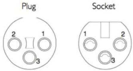
Connectors Viewed From Wiring Side
D-Type Multipin Wiring
Connectors Viewed From Wiring Side

Dimensions: 55 x 15mm (approx.)
Cable Diameter: 8mm (typical)
Screwlock thread: 440-UNC
GPIO
GP Outputs
All output switch closures are via DIL relay.
DO NOT use these outputs to directly switch capacitive or reactive loads; always use a separate external relay with suitable contact rating.
DIL Relay Ratings:
• 100V DC, 125V AC
- 100mA max.
GP Inputs
Inputs are triggered by applying an AC or DC voltage of between 4V and 24V. The current drawn is approximately 10mA. Minimum input pulse duration 50mS.
![graph TD A["Diode"] --> B["Resistor"] B --> C["Switch"] C --> D["Drain Valve"] D --> E["Terminal A"] D --> F["Terminal B"] G["V"]](/content/2026/07/1553230/images/13d0dd2f2d5c6773ddf48dc1e65c8b64a39d9b5abd2be73c795300a397c41556.jpg)
GP Inputs / Outputs
| Connector Type: | 25-way D-type male |
| Pin | Description | Notes: |
| 1 | Input 1A | See input requirements above |
| 14 | Input 1B | |
| 2 | Input 2A | |
| 15 | Input 2B | |
| 3 | Input 3A | |
| 16 | Input 3B | |
| 4 | Input 4A | |
| 17 | Input 4B | |
| 5 | ||
| 18 | ||
| 6 | ||
| 19 | ||
| 7 | +12V Output | 0.5A max (both pins), Linked to pin 13 |
| 20 | Chassis | Reference for 12V output |
| 8 | Output 1A | See contact ratings above |
| 21 | Output 1B | |
| 9 | Output 2A | |
| 22 | Output 2B | |
| 10 | Output 3A | |
| 23 | Output 3B | |
| 11 | Output 4A | |
| 24 | Output 4B | |
| 12 | ||
| 25 | ||
| 13 | +12V Output | As pin 7 |
Appendix C – Performance Specifications
| Mic/Line Inputs | ||
| Parameter | Value | Notes |
| Gain Range | +5 to 79 dB | 0 dBFS, MDAC continuous gain |
| Maximum Input Level | +28 dBu | Pad inserted |
| Frequency Response | ± 0.25 dB | Mic mode, 20 Hz - 20 kHz (@48kHz) -0.5 dBu signal level |
| Equivalent Input Noise | < -123 dB | Mic mode, 70 dB gain, A-weighted filter, 22 kHz bandwidth. |
| Usable Dynamic Range | > 114 dB | Mic mode, 0 dBFS, A-weighted filter, 22 kHz bandwidth. |
| Input Impedance | 1.5 kΩ / 14 kΩ | Mic / Line. Selectable per channel |
| CMRR | > 55 dB (typically > 65 dB) > 80 dB (typically > 90 dB) | Mic mode, 50 Hz - 20 kHz, 0 dBu Mic mode, 1 kHz, 0 dBu |
| Crosstalk | < -85 dB typically < -95 dB | 20 Hz - 20 kHz |
| THD+N | < 0.005 % < 0.0015 % | Mic mode, 20 Hz - 20 kHz, -6 dBu, 22 kHz bandwidth Mic mode, 1 kHz, -6 dBu, 22 kHz bandwidth |
| Phantom Power (Mic Input) | +48 V ±4 V 10 mA | Selectable per channel |
| Pad (Mic Input) | 20 dB | Selectable per channel |
| Operating Levels | +24, +22, +20, +18, +15 dBu | |
| Sample Rates | 48 or 96 kHz | |
| Resolution | 24 bit | |
| Group Delay | 39 samples | Analogue to Dante module |
Measurement Parameters
Sample Rate: 48 kHz
Operating Level: +24 dBu = 0 dBFS
Mic input termination: 150Ω
Mic Mode Gain: 24 dB (unless stated otherwise)
Reference frequency: 1 kHz (unless stated otherwise)
| Line Outputs | ||
| Parameter | Value | Notes |
| Maximum Output Level | +24 dBu | 600 Ω / 10 kΩ load |
| Output Impedance | < 50 Ω | |
| Frequency Response | ± 0.2 dB- 0.5 dB | -0.5 dBFS, 20 Hz - 15 kHzAt 20 kHz |
| Usable Dynamic Range | > 113 dB | 0 dBFS, A-weighted filter, 22 kHz bandwidthTypically >117 dB. |
| Crosstalk | <-90 dBtypically < -100 dB | 20 Hz - 20 kHz, 0 dBFS |
| THD+N | < 0.004 %< 0.004 % | 20 Hz - 20 kHz, -10 dBFS, 22 kHz bandwidth1 kHz, 0 dBFS to -20 dBFS, 22 kHz bandwidth |
| Output Symmetry | > 40 dB | 20 Hz - 20 kHzTypically > 50 dB |
| Operating Levels | +24, +22, +20,+18, +15 dBu | |
| Sample Rates | 48 or 96 kHz | |
| Resolution | 24 bit | |
| Group Delay | 31 samples | Analogue to Dante module |
Measurement Parameters
Sample Rate: 48 kHz
Operating Level: +24 dBu = 0 dBFS
Reference frequency: 1 kHz (unless stated otherwise)
Appendix D – Safety Notices
General Safety
- Please read and keep this document.
- Adhere to all warnings and follow instructions.
- This electrical equipment should not be used near water.
- Cleaning should only be with dry cloths or products compatible with electrical devices - never when the unit is powered.
- Keep the unit free of dust and use in a clean environment.
- Do not use near any heat source or in direct sunlight.
- Do not use near naked flames.
- Do not place heavy objects on the unit.
- Only use attachments/accessories recommended by the manufacturer.
-
Unplug the device during lightning storms or long periods of nonuse.
-
The unit can only be serviced by qualified personnel – Seek immediate service if:
I. The unit has been exposed to moisture
II. The unit has been dropped
III. The unit does not operate normally
- Do NOT modify this unit – alterations may affect performance, safety and/or international compliance standards.
- SSL does not accept liability for damage caused by maintenance, repair or modification by unauthorised personnel.
Installation Notes
- When installing this apparatus either fix it into a standard 19" rack or place the apparatus on a secure level surface.
- When this apparatus is rack mounted, fit all rack screws. Rack shelves are recommended for this apparatus.
- Allow a 1U gap above and below this apparatus for cooling.
- Do not obstruct any ventilation cut-outs or exhaust fans.
- Ensure that no strain is placed on any cables connected to this apparatus. Ensure that all such cables are not placed where they can be stepped on, pulled or tripped over.
Power Safety
-
The unit is not supplied with a mains lead allowing you to use IEC distribution of mains cables of your choice. Any mains cable used must fulfill the following:
I. Refer to the ratings label on the rear of the unit and always use suitable mains cords.
II. The unit should ALWAYS be earthed with the earth on both the IEC sockets (when both are used).
III. Please use - compliant 60320 C13 TYPE SOCKET. When connecting to supply outlets ensure that appropriate sized conductors and plugs are used to suit local electrical requirements.
IV. Maximum cord length should be 4.5m (15').
V. The cord should bear the approval mark of the country in which it is to be used. -
The appliance coupler is used as the disconnect device, ensure that it is connected to an unobstructed wall outlet.
-
The unit is designed for connection to single phase supplies only.
-
The clear markings regarding redundant power supplies detailed on the unit must be transferred into the installation to ensure both power sources are removed before qualified personnel service the unit.
GB The apparatus shall be connected to mains socket outlets with a protective earthing connection
ATTENTION ! This equipment must be Earthed. Refer to manual for installation instructions.
CAUTION ! Disconnect all power sources before removing any panel(s). No user-serviceable parts inside – to be serviced only by qualified personnel.

WARNING ! Un-Earthed metal parts may be present inside enclosure. Check for hazardous voltages before touching.
For protection against risk of fire – replace only with same type / rating of fuse. Do not expose to rain or moisture.
For EU

The stagebox is CE compliant and fully conforms with the current protection requirements of the European community council directives on EMC and LVD. Note that any cables supplied with SSL equipment may be fitted with ferrite rings at each end. This is to comply with the current regulations and these ferrites should not be removed. Any modifications to this equipment may adversely affect the CE compliance of this product.
Environmental Declaration

The symbol shown here, which is on the product or its packaging, indicates that this product must not be disposed of with other waste. Instead, it is the user's responsibility to dispose of their waste using a designated collection point for recycling of waste electrical and electronic equipment. The separate collection and recycling of your waste equipment at the time of disposal will help to conserve natural resources and ensure that it is recycled in a manner that protects human health and the environment. For more
information about where you can dispose of your waste equipment for recycling, please contact your local city office, your household waste disposal service or where you purchased the product.
RoHS Notice
Solid State Logic has conformed and this product has conformed to European Union's Directive 2011/65/EU on Restrictions of Hazardous Substances (RoHS) as well as the following sections of California law which refer to RoHS, namely sections 25214.10, 25214.10.2, and 58012, Health and Safety Code; Section 42475.2, Public Resources Code.
For USA
To the User:
- Do not modify this unit! This product, when installed as indicated in the instructions contained in the installation manual, meets FCC requirements.
- Important: This product satisfies FCC regulations when high quality shielded cables are used to connect with other equipment. Failure to use high quality shielded cables or to follow the installation instructions may cause magnetic interference with appliances such as radios and televisions and will void your FCC authorisation to use this product in the USA.
- Note: This equipment has been tested and found to comply with the limits for a Class A digital device, pursuant to part 15 of the FCC Rules. These limits are designed to provide reasonable protection against harmful interference when the equipment is operated in a commercial environment. This equipment generates, uses, and can radiate radio frequency energy and, if not installed and used in accordance with the instruction manual, may cause harmful interference to radio communications. Operation of this equipment in a residential area is likely to cause harmful interference in which case the user will be required to correct the interference at his own expense.
Electromagnetic Compatibility
EN55103-1:2009, EN55103-2:2009 Environments E1, E2, E3 and E4
Typical average initial in-rush current: 1.2 A, 5 sec in-rush current: 0.8 A
The audio input/output and network ports are screened-cable ports and any connections to them should be made using braid-screened cable and metal connector shells in order to provide a low impedance connection between the cable screen and the stagebox. All network connections should be of Cat5e standard or above.
Environmental
Temperature
Vibration
Shock
Operating: +5 to 40 deg. C
Operating: < 0.2 G (5-200 Hz)
Operating: < 3 G (11 ms max.)
Storage: -20 to 50 deg. C
Non-operating: < 0.4 G (5–200 Hz)
Non-operating: < 10 G (11 ms max.)


- PLEASE READ ALL INSTRUCTIONS, PAY SPECIAL HEED TO SAFETY WARNINGS
- TABLE OF CONTENTS
- INTRODUCTION
- HARDWARE CONNECTIONS
- SSL NETWORK I/O CONTROLLER
- OWNERSHIP
- GAIN COMPENSATION
- PAD
- DANTE CONTROLLER
- APPENDIX A - GENERAL SPECIFICATIONS
- APPENDIX B - CONNECTOR PIN OUTS
- APPENDIX C
- PERFORMANCE SPECIFICATIONS
- APPENDIX D - SAFETY NOTICES
- OVERVIEW
- KEY FEATURES
- STATUS LEDS AND USER BUTTONS
- CHANNEL LEDS
- DEVICE RESET
- BROOKLYN RESET
- THE GUI
- NETWORK VIEW
- DEVICE
- SELECTED
- A RED HIGHLIGHT INDICATES A DEVICE THAT REQUIRES OPERATOR ACTION
- PSU TALLIES
- INPUTS/OUTPUTS
- INPUTS
- FOCUS WINDOW
- OUTPUTS
- GPIO
- SETUP
- COMPENSATED PORTS
- CALIBRATION POINT
- RECALIBRATE INDICATION
- TRADITIONAL
- AUTOPAD
- NETWORK CONFIG
- DEVICE INFO
- APPENDICES
- APPENDIX A – GENERAL SPECIFICATIONS
- VENTILATION
- XLR WIRING
- D-TYPE MULTIPIN WIRING
- GP OUTPUTS
- DIL RELAY RATINGS
- GP INPUTS
- APPENDIX D – SAFETY NOTICES
- GENERAL SAFETY
- INSTALLATION NOTES
- POWER SAFETY
- FOR EU
- ENVIRONMENTAL DECLARATION
- ROHS NOTICE
- FOR USA
- TO THE USER
- ELECTROMAGNETIC COMPATIBILITY
- ENVIRONMENTAL
Brand : Solid State Logic
Model : SB 8.8
Category : Uncategorized