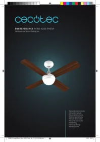
Energysilence Aero 4200 Fresh - Ceiling fan CECOTEC - Free user manual and instructions
Find the device manual for free Energysilence Aero 4200 Fresh CECOTEC in PDF.


| Product type | Ceiling fan |
| Brand | Cecotec |
| Model | Energysilence Aero 4200 Fresh |
| Diameter | 106 cm (42 inches) |
| Number of blades | 3 |
| Blade material | ABS |
| Adjustable speeds | 6 speeds |
| Summer/winter reverse function | Yes |
| Motor type | Silent DC motor |
| Power | 45 W |
| Supply voltage | 220-240 V ~ 50/60 Hz |
| Weight | 5.2 kg |
| Dimensions (L x W x H) | 106 x 106 x 35 cm |
| Recommended ceiling height | 2.5 m minimum |
| Maximum airflow | 150 m³/min |
| Maximum noise level | 45 dB(A) |
| Remote control included | Yes, with wall bracket |
| Integrated lighting | No |
| Fresh mode | Integrated ionizer for fresh air |
| Installation | Ceiling mounting kit included |
| Maintenance and cleaning | Clean with a soft, dry cloth. Do not use abrasive products. |
| Safety | Do not insert objects into the fan. Maintain a minimum distance of 2.3 m from the floor. |
| Spare parts and repairability | Parts available through Cecotec after-sales service. |
| Warranty | 2 years |
Frequently Asked Questions - Energysilence Aero 4200 Fresh CECOTEC
User questions about Energysilence Aero 4200 Fresh CECOTEC
0 question about this device. Answer the ones you know or ask your own.
Ask a new question about this device
Download the instructions for your Ceiling fan in PDF format for free! Find your manual Energysilence Aero 4200 Fresh - CECOTEC and take your electronic device back in hand. On this page are published all the documents necessary for the use of your device. Energysilence Aero 4200 Fresh by CECOTEC.
USER MANUAL Energysilence Aero 4200 Fresh CECOTEC
Safety instructions 7
-
Parts and components 38
-
Before use 38
-
Product assembly 38
-
Operation 42
-
Cleaning and maintenance 43
-
Technical specifications 43
-
Disposal of old electrical appliances 43
-
Technical support and warranty 43
SOMMAIRE
Read these instructions thoroughly before using the appliance. Keep this instruction manual for future reference or new users. Make sure that the mains voltage matches the voltage stated on the rating label of the appliance and that the wall outlet is grounded.
Check the power cord regularly for visible damage. If the cord is damaged, it must be replaced by the official Technical Support Service of Cecotec in order to avoid any type of danger.
Do not use the appliance if its cord, plug, or housing is damaged, nor after it malfunctions or has been dropped or damaged in any way.
The appliance shall be installed in accordance with national wiring regulations.
Never insert objects or body parts between rotating fan blades. To reduce the risk of injury, attach the fan directly to the support structure of the building as indicated in this manual and use only parts and components provided by Cecotec.
Turn off the mains power by turning off the circuit breakers before installing your fan to avoid risk of electric shock.
Switch off the power before connecting or repairing the fan.
The electrical wiring must be in accordance with the local regulations.
The fan must be properly grounded to avoid the risk of electric shocks.
The appliance shall be installed in accordance with national wiring regulations.
Never mount the fan in a moist or wet room.
Be careful when working near the rotating blades.
To control the fan blades' speed only use the speed control provided by Cecotec.
Do not bend the blade-attachment system during the installation or cleaning process.
Cleaning and maintenance must be carried out according to this instruction manual to make sure the appliance functions properly. Turn off and unplug the appliance before cleaning it. Make sure the fan is not placed close to curtains or other objects that could tangle.
In order to ensure your children's' safety, please keep all packaging (plastic bags, boxes, polystyrene etc.) away from their reach.
This appliance is not intended to be used by children or persons with reduced physical, sensory or mental capabilities or lack of experience and knowledge, unless they have been given supervision or instruction concerning the use of the appliance in a safe way and understand the hazards involved.
Do not allow children to play with the appliance. Close supervision is necessary when the appliance is being used by or near children.
Warning:
It is recommended to install this product between 2 people.
This product is designed for indoor use. Do not use it for industrial or commercial purposes.
Battery instructions
Keep batteries away from children and animals, they could be deadly if swallowed. In case of ingestion, seek medical assistance immediately.
Should a battery have leaked, do not allow your skin, eyes or mucous membranes to come into contact with the battery acid.
Warning: In case of contact with acid, rinse the affected areas with abundant fresh water immediately and contact a doctor as soon as possible. Make sure the battery contacts in the
device are clean before inserting batteries; if they are not, clean them. Use only the battery type specified in the technical specifications.
Always change all batteries at the same time and do not use different batteries of different types or different capacity.
When replacing batteries, note the correct polarity (+/-). Take the batteries out of the device when they are discharged or when the device is not going to be used in a long time.
Batteries must not be recharged or reactivated, dismantled, thrown into fire, immersed in fluids or short-circuited.
INSTRUCTIONS DE SÉCURITÉ
EnergySilence Aero 4200 Fresh
- Canopy
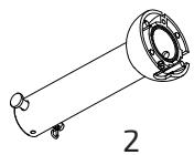
- Downrod and hanging ball
- Mounting bracket
- Blades
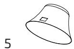
- Decorative cover
- Motor
- Spiral
- Lamp
- Remote control
2. BEFORE USE
Take all the product components out of the box and make sure all of them are included and in good conditions.
If any sign of visible damage is observed, contact immediately with our official Technical Support Service.
3. PRODUCT ASSEMBLY
The following tools are required to carry out the installation: screwdriver, flat-head screwdriver, adjustable pliers or wrench, stepladder, wire cutter, epoxy resin and rated electrical tape.
General assembly instructions The minimum carrying capacity of the outlet box from which the fan is hung must be 100 kg.
Fig. 2.
Make sure that the building structure can hold the full weight of the fan.
This fan can be installed on a normal or vaulted ceiling with a down rod. The hanging length can be extended by using a longer down rod.
Fig. 3.
Standard assembly where the device hangs from a straight flat ceiling.
Standard assembly
Support
Angled assembly where the device hangs from a vaulted or angled ceiling.
Angled assembly
Support
Mounting bracket assembly
Wooden ceiling
Fig. 4.
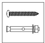
Use the 4 provided self-tapping screws with its corresponding 4 washers to fix the mounting bracket to the ceiling.
Concrete ceiling
Fig. 5.
Drill 2 8-mm holes on the concrete ceiling.
Cover the surface of the bolt with epoxy resin and introduce them in the drilled holes.
Let them sit for the time indicated on the product's box.
Then, introduce the visible part of the bolts in the mounting plate's holes.
Fix the mounting plate to the bolts by screwing first the regular washer, then the lock washer and finally the nut.
Hanging the fan
Fig. 6.
Electric wiring
Canopy
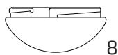
Decorative cover
Hanging ball slot
Stop pin
Stop pin clip
Adapter
Screws
Note: If you wish to extend the fan's hanging length, remove the hanging ball from the downrod provided and use the extended down rod (included).
Remove the hanging ball from the down rod by loosening the screws in it and remove the stop pin's clip and the stop pin.
Slide down the hanging ball from the original down rod to remove it.
Pass the desired down rod through the decorative cover's centre hole and then introduce it in the hanging ball again. Make sure the hanging ball is placed in the end with 2 pin holes and 1 screw hole.
Use the screws provided to tighten back the hanging ball to the rod and insert the stop pin and stop pin's clip again.
ENGLISH
Note: Make sure the stop pin is aligned with the slots inside the hanging ball.
Loosen the screws and nuts on the top part of the motor housing and remove the pin and clip from the down rod.
Slide the down rod through the canopy.
Pass the cables through the down rod. To do it more easily, it is recommended to apply some rated electrical tape on the end in order to keep them together while passing through the down rod. Carefully pull from the cables to ensure there is enough cable length to continue with the assembly.
Introduce the down rod in the motor housing's hole and reinsert the stop pin and stop pin's clip that were previously removed.
Use 2 screws to fix the canopy to the motor housing.
Warning: The important safety precautions and instructions stated in this manual are not meant to cover all possible conditions and situations that may occur. Bear in mind that common sense and caution are necessary factors in the installation and operation of this fan.
Cable connection
The connection cables coming out from the down rod and hanging ball must be connected following the below diagram.
Fig. 7.
-
Ground wire
-
L
-
N
-
Input L (black)
-
N input (white)
Remote control receiver
Cable instructions
Before handling the cables, make sure all the poles are disconnected from the power supply.
The fan includes a remote control unit with radio frequency, it does not have a speed control chain. It can only be controlled through the remote control inside the box.
-
Rotation inversion L (brown)
-
L light (blue)
-
L fan (black)
-
N (white)
-
Rotation inversion (brown)
-
Green/yellow stripe
- L light (blue)
- L fan (black)
- N (white) Neutral
Receiver
Warning: 2 people are needed to carry out the cable connection step. It is suggested that 1 person holds the assembled device while the other one connects the cables.
Canopy assembly
Fig. 8.
Raise the canopy to the mounting bracket, aligning the loosened screws in the mounting bracket with the holes in the canopy.
Twist the canopy until both screws safely hold the device, reinsert the screws and tighten them with a screwdriver.
Note: For safety reasons, it is suggested that 1 person holds the stepladder during this step.
Blade assembly
Fig. 9.
Time saver: Washers for blade screws can be set on each blade screw prior to installing blades. Align blade holes with motor screw holes, securing tighten all the screws once all the blades are attached. Before securing screws permanently, repeat with remaining blade arms.
Note: Tighten blade screws twice a year.
LED lamp support
Fig. 10.
Unscrew the motor plates' screws and tidy all the cables placing them in their position. Align the holes on the back part of the LED pan with the 3 screws on the motor's plate.
Fig. 11.
Then, screw the 3 screws on the LED plate's holes and make sure that the light set is fixed and does not move.
Place the cover and the lamp again on the LED.
Glass shade assembly
Fig. 12.
Restore the cover and the lamp shade back to the LED pan, and secure them with decorative clips and bolt nuts.
ENGLISH
4. OPERATION
Fig. 13.
- Power light indicator
- Speed control
- Off button
- Timer
- Lamp
- Winter/summer function (blade spinning inversion)
The indicator will light up while the product is operating.
Use the 3 speed buttons to select the air power level: low, medium or high.
Press the off button to turn the device off.
Use the 2 timer buttons to select the fan's operation time: 1, 3, or 4 hrs. The fan will turn off once the selected time has elapsed.
Press the light button to turn the fan's lamp on and off.
The remote control requires 2 x 1.5 V-3AAA batteries.
Winter function: if it is cold, press for blades to move hot air stuck close to the ceiling around.
Summer function: if it is hot, press again for blades to create a refreshing breeze.
Warning: Invert the fan's spinning direction while it is operating. Hold down the button for approx. 3 seconds, the device will beep, and the blades will start slowing down until they practically stop spinning. After a few seconds, they will start spinning again in the opposite direction.
Warning:
The remote control operates through RF Wireless digital transmission technology. If both the fan and the lamp are equipped with switch, turn on the fan at top speed and turn the light on before using the remote control.
If the fan or the light cannot be controlled through the remote control, check if the batteries in the remote control are in good conditions and if the make good contact, that the positive and negative electrodes are in the correct position and if the batteries are charged.
If the fan or the light cannot be controlled through the remote control, check if there are other products with remote control in the same are and check if the transmitter buttons are pressed. Product with similar remote control system could cause interference. This does not include infrared remote controls.
Pay attention to the product's voltage. Too low voltage may cause the remote control to not work. The technical specifications are indicated in this manual.
If the remote control is not going to be used for a long time, remove the batteries.
5. CLEANING AND MAINTENANCE
Make sure to disconnect the fan before cleaning it.
Do not immerse any of the parts of the device in water or splash them with any other liquid.
Do not use solvents or any other chemical products for cleaning it.
Use a soft, damp cloth to clean the device's surface.
6. TECHNICAL SPECIFICATIONS
Model:
EnergySilence Aero 4200 Fresh
Product reference:
05980
55 W, 220-240 V \~ 50/60 Hz
15 W LED
Made in China | Designed in Spain
7. DISPOSAL OF OLD ELECTRICAL APPLIANCES

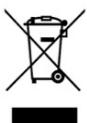
The European directive 2012/19/EU on Waste Electrical and Electronic Equipment (WEEE), specifies that old household electrical appliances must not be disposed of with the normal unsorted municipal waste. Old appliances must be collected separately, in order to optimise the recovery and recycling of the materials they contain and reduce the impact on human health and the environment.
The crossed out “wheeled bin” symbol on the product reminds you of your obligation to dispose of the appliance correctly.
Consumers must contact their local authorities or retailer for information concerning the correct disposal of old appliances and/or their batteries.
8. TECHNICAL SUPPORT AND WARRANTY
This product is under warranty for 2 years from the date of purchase, as long as the proof of purchase is submitted, the product is in perfect physical condition, and it has been given proper use, as explained in this instruction manual.
The warranty will not cover the following situations:
The product has been used for purposes other than those intended for it, misused, beaten, exposed to moisture, immersed in liquid or corrosive substances, as well as any other fault attributable to the customer.
ENGLISH
The product has been disassembled, modified, or repaired by persons, not authorised by the official Technical Support Service of Cecotec.
Faults deriving from the normal wear and tear of its parts, due to use.
The warranty service covers every manufacturing defects of your appliance for 2 years, based on current legislation, except consumable parts. In the event of misuse, the warranty will not apply.
If at any moment you detect any problem with your product or have any doubt, do not hesitate to contact Cecotec Technical Support Service at +34 963 210 728.
1. PIÈCES ET COMPOSANTS
Img. 0
Img. 1.
EnergySilence Aero 4200 Fresh
Référence :
05980
55 W, 220-240 V \~ 50/60 Hz
15 W LED
EnergySilence Aero 4200 Fresh
Produktreferenz:
05980
55 W, 220-240 V \~ 50/60 Hz
15 W LED
EnergySilence Aero 4200 Fresh
EnergySilence Aero 4200 Fresh
EnergySilence Aero 4200 Fresh
EnergySilence Aero 4200 Fresh
Made in China | Designed in Spain
7. RECYKLING SPRZĘTU AGD
EnergySilence Aero 4200 Fresh
Reference produktu:
05980
55 W, 220-240 V \~ 50/60 Hz
15 W LED
Fig./Img./Abb./Afb./Rys./Obr. 0



7
9
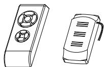
Fig./Img./Abb./Afb./Rys./Obr. 1
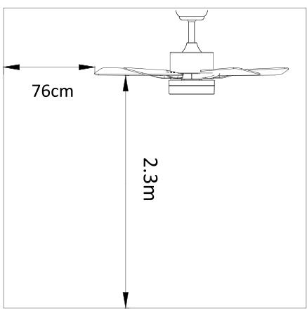
Fig./Img./Abb./Afb./Rys./Obr. 2

Fig./Img./Abb./Afb./Rys./Obr. 3

Fig./Img./Abb./Afb./Rys./Obr. 4
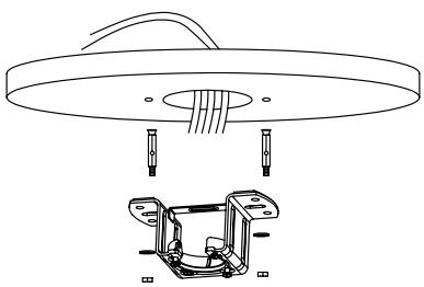
Fig./Img./Abb./Afb./Rys./Obr. 5
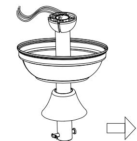

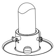
Fig./Img./Abb./Afb./Rys./Obr. 6
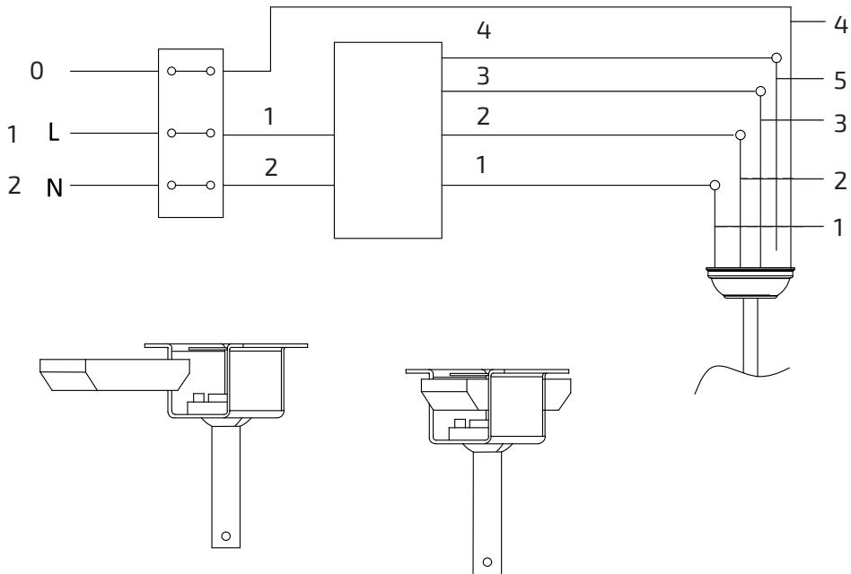
Fig./Img./Abb./Afb./Rys./Obr. 7
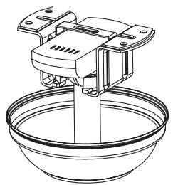


Fig./Img./Abb./Afb./Rys./Obr. 8

Fig./Img./Abb./Afb./Rys./Obr. 9
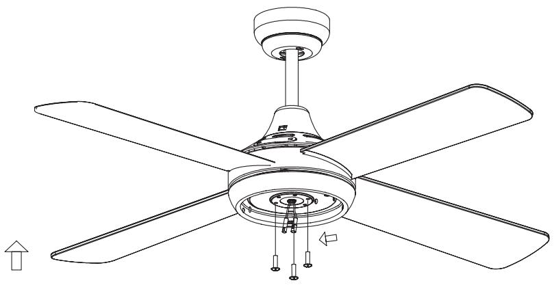
Fig./Img./Abb./Afb./Rys./Obr. 10
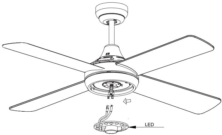
Fig./Img./Abb./Afb./Rys./Obr. 11
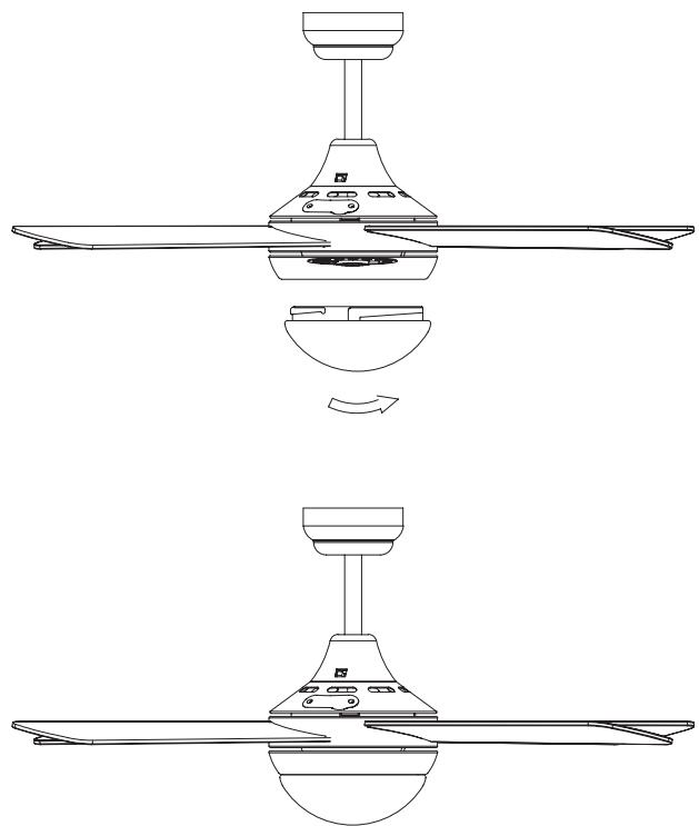
Fig./Img./Abb./Afb./Rys./Obr. 12

Fig./Img./Abb./Afb./Rys./Obr. 13
www.cecotec.es
Quart de Poblet, Valencia (Spain)
YV_01210108
- SOMMAIRE
- INSTRUCTIONS DE SÉCURITÉ
- BEFORE USE
- PRODUCT ASSEMBLY
- Fig. 2.
- Fig. 3.
- ENGLISH
- Cable connection
- Cable instructions
- Receiver
- Canopy assembly
- Blade assembly
- LED lamp support
- Glass shade assembly
- OPERATION
- Fig. 13.
- Warning:
- CLEANING AND MAINTENANCE
- TECHNICAL SPECIFICATIONS
- DISPOSAL OF OLD ELECTRICAL APPLIANCES
- TECHNICAL SUPPORT AND WARRANTY
- PIÈCES ET COMPOSANTS
- RECYKLING SPRZĘTU AGD
Brand : CECOTEC
Model : Energysilence Aero 4200 Fresh
Category : Ceiling fan