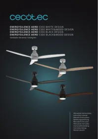
Ventilador Techo Energysilence Aero 5300 Design - Ceiling fan CECOTEC - Free user manual and instructions
Find the device manual for free Ventilador Techo Energysilence Aero 5300 Design CECOTEC in PDF.


| Product type | Ceiling fan |
| Brand | Cecotec |
| Model | Energysilence Aero 5300 Blackwood Design |
| Color | Black imitation wood (Blackwood) |
| Blade diameter | 132 cm (52 inches) |
| Blade material | Plywood with Blackwood finish |
| Number of blades | 3 |
| Motor type | Silent DC motor |
| Power supply | 220-240 V ~ 50/60 Hz |
| Power consumption | 30 W |
| Speeds | 6 |
| Reversible | Yes, for summer/winter |
| Remote control | Included with RF transmitter |
| Energy efficiency class | A+ |
| Noise level | < 35 dB |
| Net weight | 5.8 kg |
| Warranty | 2 years |
| Maintenance | Clean blades with a soft dry cloth; do not use abrasive products |
| Safety | Overload and short-circuit protection |
| Box contents | Fan, remote control, mounting kit, installation manual |
Frequently Asked Questions - Ventilador Techo Energysilence Aero 5300 Design CECOTEC
User questions about Ventilador Techo Energysilence Aero 5300 Design CECOTEC
0 question about this device. Answer the ones you know or ask your own.
Ask a new question about this device
Download the instructions for your Ceiling fan in PDF format for free! Find your manual Ventilador Techo Energysilence Aero 5300 Design - CECOTEC and take your electronic device back in hand. On this page are published all the documents necessary for the use of your device. Ventilador Techo Energysilence Aero 5300 Design by CECOTEC.
USER MANUAL Ventilador Techo Energysilence Aero 5300 Design CECOTEC
- Parts and components 48
- Before use 48
- Product assembly 49
- Operation 51
- Cleaning and maintenance 54
- Technical specifications 54
- Disposal of old electrical and electronic appliances 55
- Technical support and warranty 55
- Copyright 55
SOMMAIRE
Read these instructions thoroughly before using the product. Keep this instruction manual for future reference or new users.
- This appliance can be used by children aged 8 years and above and persons with reduced physical, sensory, or mental capabilities or lack of experience and knowledge if they have been given supervision or instruction concerning use of the appliance in a safe way and understand the hazards involved. Children must not play with the appliance. Cleaning and user maintenance should not be carried out by unsupervised children.
- The minimum distance between the fan blades and the floor must be 2.3 m.
- Make sure the appliance is unplugged from the power supply before cleaning or user maintenance.
- This appliance is designed for domestic use only and is not intended for bars, restaurants, farmhouses, hotels, motels, and offices.
- Make sure that the mains voltage matches the voltage stated on the rating label of the appliance and that the wall outlet is grounded.
- If the power cord is damaged, it must be replaced by the official Technical Support Service of Cecotec to avoid any type of danger.
- Do not use the appliance if its cord or housing are damaged, nor after it malfunctions or has been dropped or damaged in any way.
- The appliance shall be installed in accordance with national wiring regulations.
-
Never insert objects or body parts between the rotating fan blades.
-
To reduce the risk of injury, attach the fan directly to the support structure of the building as indicated in this manual and use only parts and components provided by Cecotec.
- Turn off the mains power by turning off the circuit breakers before installing your fan to avoid risk of electric shock.
- To control the speed of the fan blades, only use the means for speed control provided by Cecotec, do not use solid objects.
- Do not bend the blade-attachment system during the installation or cleaning process.
- If you are mounting the fan to a joist, make sure it is strong enough to support the moving weight of the fan.
- After installing the fan, make sure all the connections are secured. This will prevent the fan from falling.
- Turn the fan off and wait for it to stop before reversing the fan direction.
- To reduce the risk of electrical shock and personal injury, do not install the fan on a sloped ceiling.
- To reduce the risk of personal injury, use only the two steel screws and lock washers provided with the fan for mounting the outlet box.
- Make sure the installation location you choose allows the fan blades to rotate without any obstructions. Allow a minimum clearance of 2 m from the floor to the trailing edge of the blades.
- Cleaning and maintenance must be carried out according to this instruction manual to make sure the appliance functions properly. Turn off and unplug the appliance before cleaning it.
- To ensure your children's safety, please keep all packaging (plastic bags, boxes, polystyrene, etc.) out of their reach.
Instructions on batteries
- Keep the batteries out of the reach of children.
- Battery ingestion can cause burns, soft-tissue perforation, and death. It can cause severe burns within two hours of the ingestion.
- In case of battery ingestion, please seek medical help immediately.
- Do not allow children to replace the batteries without adult supervision.
- Do not disassemble, open, or break batteries.
- Keep the batteries out of the reach of children. Pay particular attention to small batteries. In case of battery ingestion, please seek medical attention immediately.
- Do not expose batteries to heat or fire. Avoid storage in direct sunlight.
- Do not short-circuit an element or a battery. Do not store batteries in an untidy manner, in a box, or drawer where they can short-circuit each other or be short-circuited by other metal objects.
- Do not subject batteries to mechanical shock.
- Both batteries and cells can leak under extreme conditions. In the event of a battery leak, keep your skin and eyes away from the liquid. If the liquid gets into contact with skin, wash immediately with soap and water. If the liquid gets into the eyes, wash them immediately with clean water for a minimum of 10 minutes and seek medical attention. Wear gloves when handling the battery or cells and dispose of it immediately in accordance with local regulations.
- Pay attention to the positive (+) and negative (-) marks on the batteries and the remote-control compartment to ensure they are inserted correctly.
-
Do not use any batteries that are not designed for use with the appliance.
-
Do not use the remote control if powered with batteries that differ in capacity, size, or type.
- Let children handle the batteries only under supervision.
- In case of battery ingestion, please seek medical attention immediately.
- Always buy the batteries recommended by the device manufacturer.
- Keep the batteries clean and dry.
- Wipe the battery terminals with a clean, dry cloth if they become dirty.
- Keep the original instruction manual for future reference.
- Use the batteries only for their intended purpose.
- Whenever possible, remove the batteries when not in use.
- Dispose of the batteries properly.
INSTRUCTIONS DE SÉCURITÉ
- Mounting bracket
- Hanging ball
- Downrod
- Stop pin clip
- Clevis pin
- Canopy
- Canopy screws
- Connections' cover
- Motor
- Blade
- Washers
- Blade screw
- Holder
- Fixing screws
- Screws
- LED lamp
- Actuator
- Remote control
The graphics in this manual are schematic representations and may not exactly match the product.
2. BEFORE USE
- This appliance is packaged in a way as to protect it during transport. Take the device out of its box and remove all packaging materials. You can keep the original box and other packaging elements in a safe place. This will help you prevent product damage when transporting it in the future. In case the original packaging is disposed of, make sure all packaging materials are recycled accordingly.
- Make sure all parts and components are included and in good conditions. If any of them are missing or not in good condition, please contact Cecotec's official Technical Support Service immediately.
-
To prevent personal injury and damage, make sure that the location where the device is going to be installed allows a 2.3-metre clearance from the blades to the floor and a 76-cm clearance from the blades to any wall or object. Fig. 2
-
Make sure that the building structure can hold the full weight of the fan.
- This fan can be installed on a normal or vaulted ceiling with a downrod. The hanging length can be extended by using a longer downrod. Fig. 3
3. PRODUCT ASSEMBLY
Installing the mounting bracket, canopy, and hanging ball
Make 8 8-mm holes in the concrete ceiling and secure the mounting bracket. It is suggested to fix it with the 2 long screws supplied within the package.
- Wooden ceiling. Fig. 4
-
Concrete ceiling. Fig. 5
-
Introduce the fan into the mounting bracket and align the hanging ball slot with the mounting bracket. Fig. 6
- To extend the hanging length of the fan, remove the hanging ball from the downrod and use the longer downrod included.
- To remove the hanging ball, loosen the set screw on the hanging ball and remove the pin and clip. Lower the hanging ball and remove the stop pin. Slide the hanging ball off the original downrod A and slide it down the longer downrod B. The top of the downrod should have a screw hole, use it to pass the screw through..
- Insert the stop pin into the top of the extended downrod and raise the hanging ball. Make sure the stop pin aligns with the slots on the inside of the hanging ball and tighten the set screw securely.
Tip
To pass the wires through the rod, wrap electrical tape around the ends of the wires. This will help to pass the wires through smoothly.
- Loosen the screws and nuts on the top part of the motor housing. Remove the pin and clip from the downrod if you have not done it previously. Slide the downrod through the canopy.
- Pass the cables through the downrod and pull the extra wire slack from the upper end of the downrod.
- Place the downrod into the motor housing and re-insert the pin and clip that were previously removed. Tighten the screws and nuts securely. Lower the canopy to the motor housing.
Fig. 7
-
Electric wiring
-
Canopy
- Decorative cover
- Hanging ball slot
- Stop pin
- Stop pin clip
- Adapter
- Screws
Canopy assembly
Fig. 8
- Raise the canopy to the mounting bracket, aligning the loosened screws in the mounting bracket with the holes in the canopy. Turn the canopy to lock it. Re-insert the screws and secure them all with a screwdriver.
- With the hanging bracket secured to the outlet box and when the assembly is completed, the fan can be hung.
- Grab the fan firmly with 2 hands. Slide the downrod through the opening in the mounting bracket and let the hanging ball rest on the mounting bracket. Turn the hanging ball slot until it lines up with the mounting bracket tab.
- Tip: seek the help of another person to hold the stepladder in place and to lift the fan up to you once you are standing on the ladder.
Blade assembly
Fig. 9
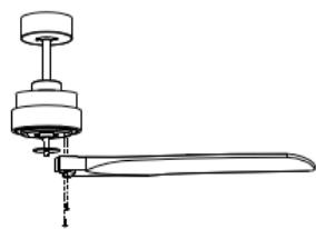
- To save time, washers for blade screws can be set on each blade screw prior to installing blades.
- Align the blade holes with the motor screw holes. Once all blades are attached, tighten all the screws. Tighten all blades screws again to ensure they are firmly fixed.
LED assembly
Fig. 10
Unscrew a set screw. Attach the LED lamp to the bottom of the fan by inserting the other 2 set screws into the key hole slots. Rotate it to place, then secure the previous set screw by aligning the screw hole and the hole at the bottom of the fan. Then, tighten the rest of the screws to secure the LED lamp.
NOTE
During the installation or when the LED lamp is removed, keep the insulation pads intact. Turning the set screws too tightly or fast will damage the insulation pads.
Lamp shade assembly
Fig. 11
Place the cover and the lamp shade on the LED lamp.
Decorative elements assembly
Fig. 12
Place the cover and the lamp shade and secure them with the decorative clips and bolt nuts.
Wiring connections
To connect the wiring between the power supply and the control unit receiver, use the connection power strip in the mounting bracket. To make the connection between the control unit receiver and the motor, connect the quick connector.
Fig. 13
WARNING
To avoid possible electric shock, make sure the electricity is turned off at the main fuse box before wiring.
- Insert the receiver into the mounting bracket with the flat side of the receiver facing the ceiling.
- Follow the instructions below to connect the fan to your house supply:
- Connect the house supply cables and the mounting bracket.
- Pay attention to the correct connection of the Live, Neutral, and Ground wires.
- Connect the 4-pin plugs of the mounting bracket to those of the remote control correctly.
- Connect the 4-pin plugs of the remote control to those of the motor correctly.
4. OPERATION
Pairing between remote control and receiver
Turn the power supply on and, within 30 seconds, press and hold the fan's remote control ON/OFF button for 5 seconds. A "beep" will be heard, indicating a successful pairing and all functions will work normally.
NOTE
The pairing initial step must be performed within 30 seconds of turning power on.
- When pairing multiple fans please ensure the isolation switch is on or that the power supply to the first installed fan is turned off prior to pairing next fans. Fans must be paired one at a time.
- Please ensure the isolation switch is kept to the ON position. The isolation switch is not to be used as a light switch as this will damage the remote control.
- If the remote-control functions are not working properly, check the batteries orientation and condition. Low battery will affect the functions of your remote control and the fan
operation. Other remote controls nearby using the same frequency may cause interference with the fan receiver.
- The remote control supports a maximum of 12 W on lighting side.
Remote control
Fig. 14
Remove battery-compartment cover of the remote control, insert the batteries, and replace the cover.
NOTE
The remote control operates with 2 x 1.5 V 3AAA batteries. If the remote control is not going to be used for a long period of time, remove the batteries to prevent damage to it and store it away from direct sunlight, heat, and moisture.
Fig. 14 key:
- ON/OFF fan button
- Speed on/control (from 1 to 6)
- Blade spinning-direction change button
- Timer (1, 2, 4 and 8 hours)
- ON/OFF light button
- Sleep mode (the fan starts running at speed 1; after 25 seconds, it switches to speed 2; after 25 seconds, it switches to speed 3; after 25 seconds, it switches to speed 1; sequentially).
When the fan is turned on, the light lights up.
Light on/off button:
- Press 1: Light off
- Press 2: First type of light
- Press 3: Light off
- Press 4: Second type of light
- Press 5: Light off
- Press 2: Third type of light
NOTE
During the installation process, make sure none of the wires are pressed, as this could cause the wires to break or short circuits.
WARNINGS
- The receiver must be correctly installed in the fan mounting bracket.
-
If the receiver does not respond to the remote-control commands, check the batteries inside the remote control or if there are any similar remote-controlled products nearby causing interference.
-
A low battery power will affect the sensitivity of the remote control and the reception signals accordingly. Replace batteries when they start to run out.
- Remove batteries from the remote control if it is not going to be used for a long period of time.
- The isolation switch must be connected.
To activate the switch, press button 3 on the remote control. This button allows you to change the rotating direction (clockwise or counterclockwise) of the fan blades.
Winter/Summer function
- Winter function: press the button on the switch (button 3) for the blades to start rotating clockwise (causing warm air to be distributed throughout the room). If this does not occur, press the button again.
- Summer function: press the button on the switch (7, Fig. 13) for the blades to start rotating counterclockwise (causing a cool breeze). If this does not occur, press the button again.
WARNING
Invert the spinning direction of the fan while in operation.. Hold down the button for approx. 3 seconds, the device will beep, and the blades will start slowing down until they practically stop spinning. After a few seconds, they will start spinning again in the opposite direction
Blade wobbling
- Ceiling fans tend to wobble due to blade movement. This is normal and not a fault. In any case, it is important to check the fan conditions periodically to ensure correct operation and avoid dangers. Therefore, check that all the blade mounting screws are tightened and safely secured.
- Wobbling problems may result from unlevelled blades or ceiling.
- To check the blade level, measure the distance from each blade tip to the ceiling.
NOTE
If measurements are irregular:
- Be sure the blade mount screws are not too tight or too loose, which may cause wobbling due to an unlevelled blade tip.
- A deformed blade can cause wobbling. Check by removing the blade and placing on a flat surface.
- Blade tracking may be checked simply by use of a household ruler. Place the ruler vertically against the ceiling and even with the outside leading edge of a blade. Note the distance of the edge of a blade compared to the others. Turn the blade slowly by hand to check the remaining blades. If a blade is not in alignment, the blade is either deformed, warped, or the blade screws are not evenly tightened or either loose.
Protection functions of the fan
Lock protection
The DC motor has a built-in safety feature against blade or motor obstruction during operation. If something obstructs the fan blades or motor, the motor will keep trying to run and then stop operation after about 30 seconds of interruption. Please remove the object or dust causing the obstruction and restart the fan.
Overload protection
The device will limit the maximum current output from the receiver/drive if the fan load has increased abnormally.
5. CLEANING AND MAINTENANCE
- Make sure that the fan is turned off before cleaning it.
- The only maintenance required for the ceiling fan is periodic cleaning.
- Use a soft and lint-free cloth to clean the product surface.
- Do not use abrasive or chemical cleaning agents, as these could cause damage to the device.
- Check periodically that the blades fixed to the motor set screws are secure and tight.
6. TECHNICAL SPECIFICATIONS
Models: EnergySilence Aero 5350 White Design/ EnergySilence Aero 5300 White&Wood Design/ EnergySilence Aero 5350 Black Design/EnergySilence Aero 5300 Black&Wood Design Reference: 05838/ 05839/ 05840/ 05841
Power: 30 W
Bulb type: LED 22 W
Voltage and frequency: 220-240 V \~ 50 Hz
This product features a light source with an energy efficiency grade F.
| Description | Symbol | Value | Unit |
| Fan maximum flow | F | 154.28 | m^3/min |
| Fan power consumption | P | 23.6 | W |
| Service value | SV | 6.54 | (m^3/min)/W |
| Power consumption on standby mode | P_SB | 0.426 | W |
| Fan sound power level | L_WA | 47 | dB (A) |
| Maximum air speed | C | 2.31 | m/seg |
| Service value measurement standard | IEC 60879 | ||
| Contact details to obtain more information | Cecotec Innovaciones S.L.C/ de la Pinadeta s/n, 46930Quart de Poblet, Valencia (Spain) | ||
Made in China | Designed in Spain
Technical specifications may change without prior notification to improve product quality.
7. DISPOSAL OF OLD ELECTRICAL AND ELECTRONIC APPLIANCES
This symbol indicates that, according to the applicable regulations, the product and/or cells must be disposed of separately from household waste. When this product reaches the end of its shelf life, you should dispose of the batteries/accumulators and take them to a collection point designated by the local authorities.
Consumers must contact their local authorities or retailer for information concerning the correct disposal of old appliances and/or their batteries.
Compliance with the above guidelines will help protecting the environment.
8. TECHNICAL SUPPORT AND WARRANTY
Cecotec shall be liable to the end user or consumer for any lack of conformity that exists at the time of delivery of the product under the terms, conditions, and deadlines established by the applicable regulations.
It is recommended that repairs be carried out by qualified personnel.
If at any moment you detect any problem with your product or have any doubt, do not hesitate to contact Cecotec's official Technical Support Service at +34 963 210 728.
9. COPYRIGHT
The intellectual property rights over the texts in this manual belong to CECOTEC INNOVACIONES, S.L. All rights reserved. The contents of this publication may not, in whole or in part, be reproduced, stored in a retrieval system, transmitted, or distributed by any means (electronic, mechanical, photocopying, recording or similar) without the prior authorization of CECOTEC INNOVACIONES, S.L.
1. PIÈCES ET COMPOSANTS
Img. 1
Se as medidas forem irregulares:
Fig./Img./Abb./Rys./Obr. 3

Fig./Img./Abb./Rys./Obr. 4

Fig./Img./Abb./Rys./Obr. 5
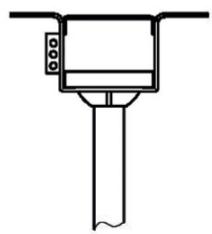
Fig./Img./Abb./Rys./Obr. 6

Fig./Img./Abb./Rys./Obr. 7
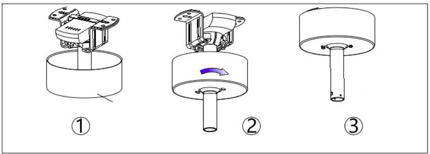
Fig./Img./Abb./Rys./Obr. 8
①

②
Fig./Img./Abb./Rys./Obr. 9
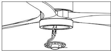

Fig./Img./Abb./Rys./Obr. 10
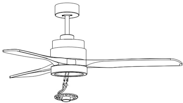
Fig./Img./Abb./Rys./Obr. 11

Fig./Img./Abb./Rys./Obr. 12

Fig./Img./Abb./Rys./Obr. 13

Fig./Img./Abb./Rys./Obr. 14
www.cecotec.es
- SOMMAIRE
- Instructions on batteries
- INSTRUCTIONS DE SÉCURITÉ
- BEFORE USE
- PRODUCT ASSEMBLY
- Installing the mounting bracket, canopy, and hanging ball
- Tip
- Fig. 7
- Canopy assembly
- Blade assembly
- LED assembly
- NOTE
- Lamp shade assembly
- Decorative elements assembly
- Wiring connections
- WARNING
- OPERATION
- Pairing between remote control and receiver
- Remote control
- WARNINGS
- Winter/Summer function
- Blade wobbling
- Protection functions of the fan
- Lock protection
- Overload protection
- CLEANING AND MAINTENANCE
- TECHNICAL SPECIFICATIONS
- DISPOSAL OF OLD ELECTRICAL AND ELECTRONIC APPLIANCES
- TECHNICAL SUPPORT AND WARRANTY
- COPYRIGHT
- PIÈCES ET COMPOSANTS
Brand : CECOTEC
Model : Ventilador Techo Energysilence Aero 5300 Design
Category : Ceiling fan