Energysilence Aero 552 Neo - Ceiling fan CECOTEC - Free user manual and instructions
Find the device manual for free Energysilence Aero 552 Neo CECOTEC in PDF.


| Product type | Ceiling fan |
| Brand | Cecotec |
| Model | Energysilence Aero 552 Neo Blackwood |
| Blade diameter | 132 cm (52 inches) |
| Number of blades | 3 |
| Blade material | Black wood (Blackwood) |
| Motor power | 55 W |
| Speeds | 6 speeds |
| Supply voltage | 220-240 V ~ 50/60 Hz |
| Net weight | 5.2 kg |
| Dimensions (h × w × d) | 45 × 132 × 132 cm |
| Minimum mounting height | 2.3 m from floor |
| Reverse switch | Yes (summer/winter) |
| Remote control | Yes, with receiver |
| Silent function | Yes (Energysilence) |
| Maximum noise level | 35 dB(A) |
| Integrated lighting | No |
| Maintenance and cleaning | Dust regularly with a soft, dry cloth. |
| Safety | Automatic shut-off in case of overheating |
| Spare parts | Available on Cecotec website |
| Repairability | Repairability index: 7.5/10 |
Frequently Asked Questions - Energysilence Aero 552 Neo CECOTEC
User questions about Energysilence Aero 552 Neo CECOTEC
0 question about this device. Answer the ones you know or ask your own.
Ask a new question about this device
Download the instructions for your Ceiling fan in PDF format for free! Find your manual Energysilence Aero 552 Neo - CECOTEC and take your electronic device back in hand. On this page are published all the documents necessary for the use of your device. Energysilence Aero 552 Neo by CECOTEC.
USER MANUAL Energysilence Aero 552 Neo CECOTEC
SAFETY INSTRUCTIONS....4
ESPAÑOL....58
ENGLISH....70
FRANÇAIS....82
DEUTSCH....94
ITALIANO....107
PORTUGUÊS....119
NEDERLANDS....131
POLSKI....143
ČEŠTINA....155
MAGYAR....166
ΕΛΛΗΝΙΚΑ......178
TÜRKÇE....190
العربية....201
CATALÀ....211
FIGURES....222
NOTA
EU01_123460 Energysilence Aero 552 Neo Black&Wood
EN • The coding in this manual is generic and applies to all code variants of the appliance.
Please read these instructions carefully before using the appliance. Keep this instruction manual for future reference or new users.
- This appliance can be used by children aged 8 years and above and people with reduced physical, sensory, or mental capabilities or lack of experience and knowledge if they have been given appropriate supervision or instruction concerning use of the appliance in a safe way and understand the hazards involved. Children must not play with the appliance. Cleaning and user maintenance must not be carried out by children without supervision.
- Keep a minimum distance of 2.3 cm between the fan blades and the floor.
- Keep a minimum distance of 76 cm between the fan blades and the wall or any other object.
- Make sure the appliance is unplugged from the power supply before cleaning or user maintenance.
- This appliance is intended for domestic use only and is not suitable for use in commercial establishments such as bars, restaurants, farms, hotels, motels, and offices.
- Make sure that the mains voltage matches the voltage specified on the appliance rating label and that the wall outlet is earthed.
- Do not use the appliance if its cable or housing are damaged, nor after it malfunctions or has been dropped or damaged in any way.
- The appliance must be installed in accordance with national wiring regulations.
- Never insert objects or body parts between the rotating fan blades.
- To reduce the risk of injury, attach the fan directly to the support structure of the building as indicated in this manual and use only parts and components provided and recommended by Cecotec.
- Cut off the power completely before installing or repairing the fan to avoid the risk of electric shock.
- The electrical wiring must be in accordance with local regulations.
- The cable must be properly earthed to avoid possible accidents.
- The appliance must be installed in accordance with national wiring regulations.
- Never install the fan in a damp or wet room.
- Be careful when near the rotating fan blades.
- To adjust the speed of the fan blades, only use the means for speed control provided by Cecotec.
- Do not bend the blade-attachment system during the installation or cleaning process.
- Cleaning and maintenance must be carried out according to this instruction manual to make sure the appliance works properly. Turn off and unplug the appliance before cleaning it.
- Make sure the fan is not placed close to curtains or other objects it may become entangled with.
- In order to ensure your children's safety, please keep all packaging (plastic bags, boxes, polystyrene, etc.) out of their reach.
- It is recommended that two people install the
appliance.
- This appliance is designed for indoor use.
Instructions on batteries
- Battery ingestion can cause burns, soft-tissue perforation, and death. It can cause severe burns within two hours of the ingestion.
- In case of battery ingestion, please seek medical attention immediately.
- Do not allow children to replace batteries without adult supervision.
- Do not disassemble, open, or damage the batteries.
- Keep the batteries out of the reach of children. Pay particular attention to small batteries. In case of battery ingestion, please seek medical attention immediately.
- Do not expose batteries to heat or fire. Avoid storage in direct sunlight.
- Do not short-circuit an element or a battery. Do not store batteries in an untidy manner, in a box, or drawer where they can short-circuit each other or be short-circuited by other metal objects.
- Both batteries and cells can leak under extreme conditions. In the event of a battery leak, keep your skin and eyes away from the liquid. If the liquid comes into contact with skin, wash immediately with soap and water. If the liquid gets into the eyes, rinse them immediately with clean water for at least 10 minutes and seek medical attention. Wear gloves to handle the battery and dispose of it immediately in accordance
with local regulations.
- Pay attention to the positive (+) and negative (-) marks on the batteries and the remote-control compartment to ensure they are inserted correctly.
- Do not use any batteries that are not designed for use with the appliance.
- Do not mix batteries of different manufacture, capacity, or size. Supervise children to prevent them from playing with batteries.
• Always buy recommended batteries. - Keep the batteries clean and dry. Wipe the battery terminals with a clean, dry cloth if they become dirty.
- Keep the original instruction manual for future reference.
- Whenever possible, remove the batteries when not in use.
1. Parts and components
Fig. 1
A. Mounting bracket
B. Canopy
C. Canopy cover
D. Downrod + hanging ball
E. Coupling cover
F. Motor assembly
G. Light kit
H. Lampshade
I. Receiver + remote control
J. Fan blade
K. Blade bracket
Note:
The graphics in this manual are schematic representations and may not exactly match the product.
2. Before use
- This appliance comes in a packaging designed to protect it during transport. Remove the appliance from its box. You can keep the original box and other packaging materials in a safe place to prevent damage to the appliance if you need to transport it in the future. If you wish to dispose of the original packaging, make sure all items are recycled properly.
- Check that all parts and components are included and in good condition. If any of them are missing or damaged, please contact Cecotec's Official Technical Support Service immediately.
Box content:
Product
- Instruction manual
ENGLISH
- Do not remove the product's serial number in order to keep proper traceability if technical assistance is required.
3. Installation
Assembly
- Loosen the locking screw on the cover until it is flush with the inner surface.
- Remove the downrod, canopy and canopy cover.
- Place the downrod inside the canopy, canopy cover and coupling cover.
- Thread the cables extending from the motor through the coupling cover, canopy, canopy cover and downrod.
- Insert the bolt through the shaft and downrod holes. Take care not to damage or cut the fan cables.
● Tighten the bolt. Secure with the clevis through the hole in the end of the bolt. - Secure the downrod in position by tightening the locking screws. Slide the coupling cover down until it sits flush with the motor housing.
Fig. 2
- Support
- Bolt
- Canopy
- Locking screw
- Locking screw
- Motor
A. Canopy
B. Downrod + hanging ball
C. Canopy decorative cover
D. Motor cover
- Open the accessory package.
- Insert the blade screw through the fiber washer and the blade. Align with the corresponding hole in the blade bracket. Repeat this step with the remaining two
ENGLISH
screws and tighten firmly.
- Check that all screws are tight.
Fig. 3
- Blade screw
- Washer
Assembling the blades on the motor
- Remove the screws from the motor assembly.
- Secure the blade bracket to the motor with the screws as shown in Figure 4.
- Turn the blade slightly after installation and repeat the same procedure for the remaining blades.
Fig. 4
- Light kit
- Screws
- Motor screw
NOTE: The fan includes three rubber stops (optional on some models) on the motor for transport only. Remove the stops before starting the motor or installing the blades on the motor.
Installing the mounting bracket
WARNING: To reduce the risk of fire, electric shock or personal injury, mount in a UL/CSA listed junction box marked as acceptable for fan support and use the mounting screws provided with the junction box.
- Secure the mounting bracket and rubber gaskets to the metal junction box.
Fig. 5
- Wooden beam
- Junction box
- Mounting bracket
- Junction box screws
- Ceiling
6. Canopy
Electrical connection
Connections according to diagram in figure 6.
A. Use approved wire connectors to connect the house power supply to the receiver wires, following the diagram and steps below:
- Connect Blue (N) of the network to Blue (N) of the Receiver (I).
- Connect Brown (L) of the network to Brown (L) of the Receiver (I).
- Connect mains ground to fan/metal structure ground, including the Receiver (I) if it has a ground terminal.
- Connect the lighting system terminals (G) to the light outputs on the receiver (I).
- Connect the wires from the motor assembly (F) to the motor outputs on the receiver (I).
NOTE: Once the earth cables are connected, carefully insert all cables and connectors inside the metal box. Ensure that the cables are kept away from the hanging ball on the downrod and mounting bracket housing to prevent pinching when hanging the assembly.
B. Placing the receiver and closing the canopy
● Push all connected cables inside the ceiling box.
● Place the receiver in the mounting bracket, as shown in Figure 7.
- When installing the canopy, ensure that it does not compress the aerial.
● Ensure that all earth cables are connected.
Fig. 7
- Mounting bracket
- Receiver
- Canopy
Installing the light kit
Fig. 8
- Remove the screws from the motor light kit.
- Connect the polarized connectors of the light kit to the corresponding connectors on the switch housing.
● Install the light kit with the screws removed in the previous step.
Fig. 8
- Cable connectors
- Light kit
- Screws
Assembling the fan
- Place two screws and washers in the mounting bracket that correspond with the canopy slots. Screw in two turns.
Attaching the hanging ball and closing the canopy
- Carefully rotate the fan assembly until the slot on the coupling cover fits over the tab on the canopy assembly.
- Loosen (do not remove) the two mounting bracket screws.
- Slide the canopy onto the mounting bracket and position the hole in the canopy over the screw in the bracket. Rotate the canopy until it locks into the narrow section of the holes.
- Align the canopy holes with the mounting bracket and secure with the two sets of screws until tight.
WARNING: Failure to snap the tab into the groove could damage the electrical wires and cause a shock or fire hazard.
Fig. 9
- Hanging ball
- Slot
- Downrod
- Mounting bracket
- Slot
- Hanging ball
- Downrod
- Decorative cover
- Canopy screw
Note for pitched roofs:
On sloped ceilings, orient the tab on the mounting bracket towards the top of the slope so that the groove on the hanging ball supports the load. Depending on the slope, a longer downrod may be required to prevent the blades from hitting the ceiling.
Installing the lampshade
- Place the panel on the fan and turn it to secure it.
Figure 10
- Motor
- Lampshade
WARNING: Ensure that all connections, set screws and screws are firmly tightened before the next step.
4. Operation
Remote control
To synchronize the controller with the receiver, follow these steps:
- Open the battery compartment cover of the controller and insert two AAA batteries (1.5V), not included.
- If the controller does not control the fan, synchronize the code between the controller and the receiver. Turn on the power and, within the first 10 seconds, press and hold the ⏻ button on the remote control for 5 seconds. A long beep will confirm successful synchronization.
- If the control does not respond, check the battery switch contact, the correct position of the poles and the charge level.
- Make sure that there are no other similar devices nearby that may interfere, as they may operate on the same frequency.
- Remove the batteries if it is not to be used for an extended period.
- When installing the fan, prevent the roof cover from pressing on the antenna or any wires to prevent damage or short circuits.
Remote control button functions
Figure 11
- Power/pairing button
- Speed setting buttons
- Light on/off button
- Timer setting buttons
- Comfort breeze mode on/off button
ENGLISH
- On/Off fan button
- Rotation direction change button (summer/winter mode)
- 5-minute timer button
- Anti-theft mode on/off button
- Silent mode activation button (no sound when pressing the buttons on the controller)
5. Cleaning and maintenance
Inspection and retightening
- Normal use may loosen some fixings. A clicking, rattling or vibration sound usually indicates loose screws.
- Every 6 months, check and retighten if necessary: Screws of the mounting bracket, hanging ball and downrod. Blade fixing screws for the motor.
Lighting system and lampshade fixing system.
● Tighten firmly without forcing to avoid damaging threads.
Cleaning
- Clean the fan periodically with a soft cloth slightly dampened with mild detergent. Dry afterwards.
- Do not use solvents, alcohol, ammonia, abrasives or scouring pads.
- Remove dust from the blades with a soft cloth or brush. Metal parts are lacquered to prevent staining, do not polish with abrasive compounds.
- Do not spray cleaners directly onto the lighting system or the lampshade.
Lubrication
- The fan does not require greasing. The bearings are permanently sealed for quiet, long-lasting operation.
Safety
● Always disconnect the mains supply at the switchboard and verify absence of voltage before carrying out any adjustment, inspection or cleaning.
● Wait for the blades to come to a complete stop before working on the fan.
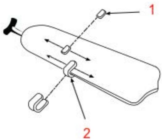
Balancing kit
The balancing kit should only be used if there is an unacceptable amount of fan oscillation after completing all the steps in the owner's manual under "Fan Blade Placement".
- Turn on the fan and adjust the speed control to a setting where the oscillation is most noticeable.
- Turn off the fan and wait for it to stop completely. Select a blade and place the balancing clip on it, midway between the blade holder and the tip, at the trailing edge.
- Switch on the fan. Observe whether the oscillation has increased or decreased. Turn off the fan, move the clip to another blade and retest. Repeat this procedure on all blades, noting on which one the greatest improvement is achieved.
- Move the clip back to the vane that showed the greatest improvement. Slide the clip in and out on this blade and operate the fan to find the position where the clip provides the greatest improvement.
- Remove the clip and install a swing weight on the top of the blade along the centerline near the point where the clip was attached.
- If the fan oscillation problem has not been corrected, you can try to improve the sway by using the sway clip and additional weights.
Fig. 12
- Balancing weight
- Plastic clip
6. Troubleshooting
Use this section only if the ventilator exhibits any of the symptoms described. Follow the checks indicated for each case, in the proposed order, and verify the result after each step. Only perform the basic maneuvers described in this section. Any intervention not contemplated here may invalidate the warranty.
If, after completing the checks, the problem persists, leave the equipment out of service and contact Cecotec's Official Technical Assistance Service for diagnosis and repair. Stop use immediately and do not attempt further checks if you observe any of these situations:
● Burning odor, smoke, sparks or repeated tripping of the circuit breaker.
- Blade strikes against the ceiling/obstacles, excessive vibration or abnormal noises that do not disappear after basic checks.
- Visible damage to cables, connectors, diffuser or housing.
The fan does not work
- Check the fuses/automatic fuses in the main circuit and branch circuits.
- Check the line conductor connections between the mains and the fan, and the
ENGLISH
connections inside the lower housing of the Motor Assembly.
CAUTION: perform these checks with the power disconnected.
- Ensure that the forward/reverse switch is firmly in the up or down position. The fan will not operate if the switch is in the intermediate position. If the change of direction is made from the remote control, select a valid direction and confirm the answer.
- Confirm that the wall switch that powers the fan is turned on.
The fan makes noise
- Ensure that all motor housing screws are tight (without over-tightening).
- Check that the screws securing the blades to the motor assembly (or to their brackets, if applicable) are tightened securely.
- Ensure that the cable connectors inside the lower housing of the motor assembly do not knock against each other or against the internal walls. CAUTION: Disconnect the power supply before accessing the housing.
- Some motors are sensitive to wall-mounted electronic speed controllers (Solid State). DO NOT USE solid state speed controllers.
- After a "settling-in period" of 24 hours, most of the noises typical of a new fan disappear.
The fan oscillates
All blades are grouped by weight, but natural wood can vary and cause oscillation. Follow these checks in order and verify the result after each step:
- Check that all blades are firmly screwed to the blade bracket.
- Check that all blade brackets are securely attached to the motor assembly.
- Ensure that the canopy and mounting bracket are securely tightened and that the ceiling box is firmly anchored to the structure.
- Blade height equalisation: select a reference point on the ceiling above the tip of one blade and measure the distance to the tip. Rotate the fan and repeat the measurement for each blade. Keep the difference within 1/8 in (≈3 mm). If the levels are not equal:
- To lower the tip of a blade: insert a thin washer (not supplied) between the blade and its bracket, together with the screw.
-
To raise the tip: insert the washer (not supplied) between the blade and its bracket on the two screws furthest from the motor assembly.
-
If oscillation persists, swapping two adjacent blades may redistribute the weight and provide smoother operation.
The light does not turn on
- Ensure that the light output from the receiver is connected to the lighting system in accordance with the diagram in Figure 4.
- Check for loose or disconnected wires in the lower housing of the motor assembly.
- Check for loose or disconnected wires in the lighting system.
- Check whether the light source is faulty. On models with integrated LEDs, confirm that the connector is properly inserted.
Warning: Switch off the main power supply before accessing the housing.
7. Technical specifications
Product: EnergySilence Aero 552 Neo Black&Wood
Product reference: EU01_123460
Voltage: 230 V\~
Frequency: 50 Hz
Motor power: 32 W
Light power: 18 W LED
| Description | Symbol | Value | Unit |
| Maximum fan airflow | F | 141 | m^3/min |
| Fan power consumption | P | 33 | W |
| Service value | SV | 4.27 | (m^3/min)/W |
| Power consumption on standby mode | PSB | 0.43 | W |
| Fan sound power level | LWA | 43 | dB (A) |
| Maximum air speed | c | 11.7 | m/sec |
| Seasonal electricity consumption | Q | kWh/a | |
| Service value measurement standard | IEC 60879:2019 | ||
| Contact details to obtain more information | Cecotec Innovaciones SL.Av. Reyes Católicos, 60, 46910, Alfajar (Valencia), Spain | ||
The power consumption in standby mode is 0,43 W using the guidelines of standard EN 50564:2011 and the European regulations 1275/2008/EC and 801/2013/EC. For this purpose, the appliance is connected to the mains supply without performing any function, waiting for standby mode to be activated.
Technical specifications may change without prior notification to improve product quality. Made in China | Designed in Spain
8. Recycling of electrical and electronic equipment

This symbol indicates that, according to the applicable regulations, the product and/or batteries must be disposed of separately from household waste. When this product reaches the end of its service life, you must remove the batteries/accumulators and take it to a collection point designated by local authorities.
For detailed information on how to properly dispose of electrical and electronic equipment and/or the corresponding batteries, consumers should contact their local authorities. Information regarding national packaging recycling systems and their marking can be found on our website.
Compliance with the above guidelines will help protect the environment.
9. Technical support and warranty
Cecotec shall be liable to the end user or consumer for any lack of conformity that exists at the time of product delivery under the terms, conditions and deadlines established by applicable regulations.
Repairs should be carried out by qualified personnel.
If at any moment you detect any problem with your product or have any doubt, do not hesitate to contact the official Cecotec Technical Support Service at +34 96 321 07 28.
10. Copyright
The intellectual property rights over the texts in this manual belong to CECOTEC INNOVACIONES, S.L. All rights reserved. The content of this publication may not, either in part or in its entirety, be reproduced, stored in a retrieval system, transmitted or distributed by any means (electronic, mechanical, photocopying, recording or similar) without prior authorisation from CECOTEC INNOVACIONES, S.L.
11. Simplified EU Declaration of Conformity
CE
Cecotec Innovaciones hereby declares that this appliance complies with the
essential requirements and other relevant provisions of the regulations applicable in the European Union. This appliance has been designed, manufactured and tested in compliance with required safety and quality standards. The full text of the EU Declaration of Conformity can be found on the following website:
https://cecotec.es/es/information/declaration-of-conformity
FRANÇAIS
https://storececotec.it/it/information/declaration-of-conformity
PORTUGUÊS
https://cecotec.es/es/information/declaration-of-conformity
POLSKI
https://cecotec.es/es/information/declaration-of-conformity
ČEŠTINA
https://cecotec.es/es/information/declaration-of-conformity
ΕΛΛΗΝΙΚΑ
https://cecotec.es/es/information/declaration-of-conformity
1 الشكل
. A قوس التثبيت
. B ظهر السفينة
غطاء .C
https://cecotec.es/es/information/declaration-of-conformity
FIGURES
FIG 1

FIG 2
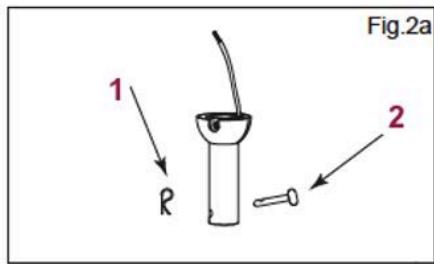


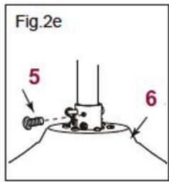
FIG 3

FIG 4

FIG 5


FIG 6
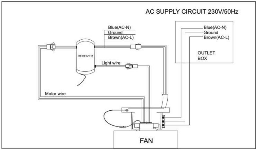
FIG 7

FIG 8

FIG 9

FIG 10

FIG 11

FIG 12
www.cecotec.es
Cecotec Innovaciones S.L. Av. Reyes Católicos, 60 46910, Alfafar, Valencia (Spain)
- NOTA
- Instructions on batteries
- Parts and components
- Fig. 1
- Note:
- Before use
- Box content:
- ENGLISH
- Installation
- Assembly
- Fig. 2
- Fig. 3
- Assembling the blades on the motor
- Fig. 4
- Installing the mounting bracket
- Fig. 5
- Canopy
- Electrical connection
- Connections according to diagram in figure 6.
- Fig. 7
- Installing the light kit
- Fig. 8
- Assembling the fan
- Attaching the hanging ball and closing the canopy
- Fig. 9
- Note for pitched roofs:
- Installing the lampshade
- Figure 10
- Operation
- Remote control
- Remote control button functions
- Figure 11
- Cleaning and maintenance
- Inspection and retightening
- Cleaning
- Lubrication
- Safety
- Balancing kit
- Fig. 12
- Troubleshooting
- The fan does not work
- The fan makes noise
- The fan oscillates
- The light does not turn on
- Technical specifications
- Recycling of electrical and electronic equipment
- Technical support and warranty
- Copyright
- Simplified EU Declaration of Conformity
- CE
- FRANÇAIS
- PORTUGUÊS
- POLSKI
- ČEŠTINA
- ΕΛΛΗΝΙΚΑ
Brand : CECOTEC
Model : Energysilence Aero 552 Neo
Category : Ceiling fan