
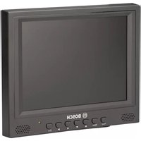
LTC 9113 - Monitor BOSCH - Free user manual and instructions
Find the device manual for free LTC 9113 BOSCH in PDF.
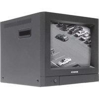


| Product Type | Monitor |
| Brand | Bosch |
| Model | LTC 9113 |
| Display Type | LCD |
| Screen Size | 9.6 inches (diagonal) |
| Resolution | 1024 x 768 pixels |
| Aspect Ratio | 4:3 |
| Input Connectors | Composite video (BNC), VGA |
| Power Supply | 100-240V AC, 50/60 Hz |
| Power Consumption | 30 W (typical) |
| Dimensions (W x H x D) | 250 x 200 x 200 mm |
| Weight | 4.5 kg |
| Mounting | Desktop or VESA mount (100 x 100 mm) |
| Operating Temperature | 0°C to 40°C |
| Storage Temperature | -20°C to 60°C |
| Key Functions | Brightness, contrast, volume adjustment; on-screen display menu |
| Cleaning | Wipe with a soft, dry cloth; do not use liquid cleaners |
| Safety | Complies with CE, FCC; use only with grounded outlet |
| Spare Parts / Repairability | Contact Bosch service center for replacement parts; limited user-serviceable parts |
| General Information | Designed for professional video monitoring applications |
Frequently Asked Questions - LTC 9113 BOSCH
User questions about LTC 9113 BOSCH
0 question about this device. Answer the ones you know or ask your own.
Ask a new question about this device
Download the instructions for your Monitor in PDF format for free! Find your manual LTC 9113 - BOSCH and take your electronic device back in hand. On this page are published all the documents necessary for the use of your device. LTC 9113 by BOSCH.
USER MANUAL LTC 9113 BOSCH
LTC 9113/00, LTC 9114/00, LTC 9115/00, LTC 9017/00, LTC 9117/00


Security Systems
Instruction Manual EN Rack-mount Kits
1 D E S C RIPTION 3 S E R V I C E
These kits are designed to mount the following monitors in a standard EIA 19in. rack using either Universal or Wide Spacing.
Rack Kit Monitor Model
LTC 9113 /00 LTC 2813 /90, & LTC 2 914/91
LTC 9114 /00 LTC 2814 /90
LTC 9115 /00 LTC 2915 /90
LTC 9017/00 LTC 2017/5 0 & LTC 2017/6 0
LTC 9117/00 LTC 2917/91
2 U N P A C K
This mechanical equipment should be unpacked and handled with care.
Check for the following items:
Qty. Item
1 B ase Tray
2 Rack Sides
1 C over Bezel
1 Hardware Kit containing the following items:
4 4-40 Machine Screws (Cover Bezel)
6 8-32 Machine Screws (Rack Sides)
4 10-32 Machine Screws (Rack Installation)
4 10-32 U-type Nut Fasteners (Rack Installation)
If an item appears to have been damaged in shipment, replace it properly in its carton and notify the shipper. If any items are missing, notify your Bosch Security Systems Inc. Sales Representative or Customer Service.
The shipping carton is the safest container in which the unit may be transported. Save it for possible future use.
If the unit ever needs repair service, the customer should contact the nearest Bosch Security Systems, Inc. Service Center for return authorization and shipping instructions.
Service Centers
USA
Phone: 800-366-2283 or 717-735-6638
fax: 800-366-1329 or 717-735-6639
CCTV Spare Parts
Phone: 800-894-5215 or 408-956-3853 or 3854
fax: 408-957-3198
e-mail: N BoschCCTVparts@ca.slr.com
Canada
Phone: 514-738-2434
Europe, Middle East & Asia Pacific Region
Phone: 32-1-440-0711
For additional information, see
www.boschsecuritysystems.com.
4 I N S T A L L ATIO
4.1 ASSEMBLY
4.1.1 Tools Required
Small Phillips screwdriver.
Assembly
- Position the monitor so that it is upside down, with its feet (where applicable) on top, and the front of the monitor toward you. Remove and retain each replacement foot and mounting screw from the monitor. Install the base tray onto the monitor with the flat side of the base tray toward the monitor; the edges of the base tray should face up. The square hole of the base tray should now be at the lower left-hand edge of the tray. Align the removable foot mounting holes with the appropriate holes in the base tray. Secure the monitor to the base tray using the reserved mounting screws from the removable feet.
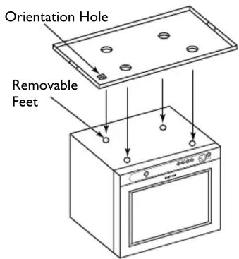
FIGURE 1 Installing the Base Tray
NOTES:
- If the monitor does not have removable feet (LTC 2917/90 and LTC 2813/60 monitors), align the pads on the monitor base with the holes in the base tray. Secure the monitor to the base with sheet metal screws (not provided); self-threading sheet metal screws with a maximum length of 19mm (3/4in.) are recommended. While attaching the monitor to base tray, do not push in the plastic stand-offs protruding from the bottom of the monitor, as this may damage the monitor's internal workings.
- When installing the LTC 9113/00, use the front-most set of holes in the base tray so that the flip-down drawer on the monitor is still accessible once installed in the rack.
- Align the two (2) rack side panels with the sides of the base tray, and attach using the six (6) supplied 8-32 screws.
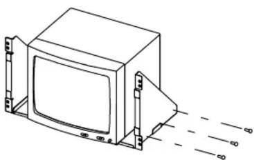
FIGURE 2 Attaching the Side Panels
- Install the unit (monitor, base tray, and 2 rack side panels) into the rack. If necessary, use the four (4) supplied 10-32 screws and U-type nut fasteners.

FIGURE 3 Installing the Unit into the Rack
- Install the cover bezel using the four (4) supplied 4-40 machine screws, inserted into the holes in the rack side panels.

FIGURE 4 Installing the Cover Bezel
Bosch Security Systems, Inc.
850 Greenfield Road
Lancaster, PA 17601 USA
Tel: 800-326-3270
Fax: 1-717-735-6560
www.boschsecuritysystems.com
Bosch Security Systems B.V.
P.O. Box 80002
5600 JB Eindhoven
The Netherlands
Tele +31 40 27 80000
Bosch Security Systems Pte Ltd.
38C Jalan Pemimpin
Singapore 577180
Republic of Singapore
Tel: 65 (6) 319 3486
© 2004 Bosch Security Systems GmbH
3935 890 14616 04-34 | Updated August 19, 2004 | Data subject to change without notice.



Brand : BOSCH
Model : LTC 9113
Category : Monitor