
UML19290 - Monitor BOSCH - Free user manual and instructions
Find the device manual for free UML19290 BOSCH in PDF.


| Product Type | Monitor |
| Brand | Bosch |
| Model | UML19290 |
| Screen Size | 19 inches |
| Resolution | 1280 x 1024 (SXGA) |
| Aspect Ratio | 5:4 |
| Panel Type | TN |
| Brightness | 250 cd/m² |
| Contrast Ratio | 1000:1 |
| Response Time | 5 ms |
| Viewing Angle (H/V) | 170° / 160° |
| Connectivity | VGA, DVI, HDMI |
| Power Consumption (Typical) | 25 W |
| Power Supply | AC 100-240 V, 50/60 Hz |
| Dimensions (W x H x D) | 420 x 380 x 180 mm |
| Weight | 4.5 kg |
| VESA Mount | 100 x 100 mm |
| Adjustability | Tilt only |
| Built-in Speakers | 2 x 1 W |
| OSD Languages | English, German, French, Spanish, Italian |
| Compliance | CE, FCC, RoHS |
| Operating Temperature | 0°C to 40°C |
| Storage Temperature | -20°C to 60°C |
| Package Contents | Monitor, power cable, VGA cable, manual |
Frequently Asked Questions - UML19290 BOSCH
User questions about UML19290 BOSCH
0 question about this device. Answer the ones you know or ask your own.
Ask a new question about this device
Download the instructions for your Monitor in PDF format for free! Find your manual UML19290 - BOSCH and take your electronic device back in hand. On this page are published all the documents necessary for the use of your device. UML19290 by BOSCH.
USER MANUAL UML19290 BOSCH
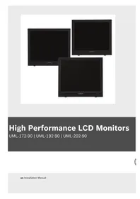
High Performance LCD Monitors
UML-172-90 | UML-192-90 | UML-202-90
Table of Contents
1 S a f e t y
1.1 Important Safety Instructions 1
1.2 Safety Precautions 4
1.3 Important Notices 4
1.4 Customer Support and Service 11
2 Unpacking 13
2.1 Parts List 13
2.2 Exploded View 14
2.3 Remote Control 16
2.4 Remote Control Battery Installation 17
3 Description
3.1 Features 19
3.2 Power 20
4 Installing the Monitor 21
4.1 Ventilation 21
4.2 Mounting the Monitor 21
4.2.1 Desktop Installation 21
4.2.2 Wall Mount Installation 22
4.3 Connecting the Composite Video Signal to the Monitor 22
4.4 Connecting the Y/C (S-Video) Signal to the Monitor 23
4.5 Connecting Audio to the Monitor 23
4.5.1 Connecting PC Audio 23
4.6 Connecting the PC Signal to the Monitor 24
4.6.1 HDMI 24
4.6.2 DVI 24
4.6.3 VGA 24
4.7 Connecting an Alarm Trigger 25
4.8 Single / Multiple Monitor Configuration 27
5 Navigating the Monitor 29
5.1 Navigating the Front Panel 29
5.2 Navigating the Monitor On-screen Display (OSD) 29
5.3 On-screen Display Menus 31
5.4 Custom Menu 31
5.5 Picture / Sound Menu 33
5.6 PIP Menu 35
5.7 Setup Menu 36
5.7.1 Configuring Alarm Relay Inputs 37
5.7.2 Configuring Auto Switching 39
6 Power Management 41
6.1 Power Consumption 41
6.2 LED Indicator 41
7 Maintenance
8 TroubleShooting Guide 45
1 S a f e t y
1.1 Important Safety Instructions
Read, follow, and retain for future reference all of the following safety instructions. Heed all warnings on the unit and in the operating instructions before operating the unit.
-
Cleaning - Unplug the unit from the outlet before cleaning. Follow any instructions provided with the unit. Generally, using a dry cloth for cleaning is sufficient, but a moist fluff-free cloth or leather shammy may also be used. Do not use liquid cleaners or aerosol cleaners.
-
Heat Sources - Do not install the unit near any heat sources such as radiators, heaters, stoves, or other equipment (including amplifiers) that produce heat.
-
Ventilation - Any openings in the unit enclosure are provided for ventilation to prevent overheating and ensure reliable operation. Do not block or cover these openings. Do not place the unit in an enclosure unless proper ventilation is provided, or the manufacturer's instructions have been adhered to.
-
Water - Do not use this unit near water, for example near a bathtub, washbowl, sink, laundry basket, in a damp or wet basement, near a swimming pool, in an outdoor installation, or in any area classified as a wet location. To reduce the risk of fire or electrical shock, do not expose this unit to rain or moisture.
-
Object and liquid entry - Never push objects of any kind into this unit through openings as they may touch dangerous voltage points or short-out parts that could result in a fire or electrical shock. Never spill liquid of any kind on the unit. Do not place objects filled with liquids, such as vases or cups, on the unit.
-
Lightning - For added protection during a lightning storm, or when leaving this unit unattended and unused for long periods, unplug the unit from the wall outlet and
disconnect the cable system. This will prevent damage to the unit from lightning and power line surges.
-
Controls adjustment - Adjust only those controls specified in the operating instructions. Improper adjustment of other controls may cause damage to the unit. Use of controls or adjustments, or performance of procedures other than those specified, may result in hazardous radiation exposure.
-
Overloading - Do not overload outlets and extension cords. This can cause fire or electrical shock.
-
Power cord and plug protection - Protect the plug and power cord from foot traffic, being pinched by items placed upon or against them at electrical outlets, and its exit from the unit. For units intended to operate with 230 VAC, 50 Hz, the input and output power cord must comply with the latest versions of IEC Publication 227 or IEC Publication 245.
-
Power disconnect - Units with or without ON/OFF switches have power supplied to the unit whenever the power cord is inserted into the power source; however, the unit is operational only when the ON/OFF switch is in the ON position. The power cord is the main power disconnect device for switching off the voltage for all units.
-
Power sources - Operate the unit only from the type of power source indicated on the label. Before proceeding, be sure to disconnect the power from the cable to be installed into the unit.
- For battery powered units, refer to the operating instructions.
- For external power supplied units, use only the recommended or approved power supplies.
- For limited power source units, this power source must comply with EN60950. Substitutions may damage the unit or cause fire or shock.
- For 24 VAC units, voltage applied to the unit's power input should not exceed ± 10% , or 28 VAC. User-supplied wiring must comply with local electrical
codes (Class 2 power levels). Do not ground the supply at the terminals or at the unit's power supply terminals.
- If unsure of the type of power supply to use, contact your dealer or local power company.
- Servicing - Do not attempt to service this unit yourself. Opening or removing covers may expose you to dangerous voltage or other hazards. Refer all servicing to qualified service personnel.
-
Damage requiring service - Unplug the unit from the main AC power source and refer servicing to qualified service personnel when any damage to the equipment has occurred, such as:
-
the power supply cord or plug is damaged;
- exposure to moisture, water, and/or inclement weather (rain, snow, etc.);
– liquid has been spilled in or on the equipment; - an object has fallen into the unit;
- unit has been dropped or the unit cabinet is damaged;
- unit exhibits a distinct change in performance;
-
unit does not operate normally when the user correctly follows the operating instructions.
-
Replacement parts - Be sure the service technician uses replacement parts specified by the manufacturer, or that have the same characteristics as the original parts. Unauthorized substitutions may cause fire, electrical shock, or other hazards.
- Safety check - Safety checks should be performed upon completion of service or repairs to the unit to ensure proper operating condition.
- Installation - Install in accordance with the manufacturer's instructions and in accordance with applicable local codes.
- Attachments, changes or modifications - Only use attachments/accessories specified by the manufacturer. Any change or modification of the equipment, not expressly approved by Bosch, could void the warranty or,
in the case of an authorization agreement, authority to operate the equipment.
1.2 Safety Precautions

WARNING! High risk:
This symbol indicates an imminently hazardous situation such as “Dangerous Voltage” inside the product. If not avoided, this will result in an electrical shock, serious bodily injury, or death.

WARNING! Medium risk:
Indicates a potentially hazardous situation. If not avoided, this could result in serious bodily injury or death.
CAUTION! Medium risk:
Indicates a potentially hazardous situation. If not avoided, this may result in minor or moderate injury. Alerts the user to important instructions accompanying the unit.

WARNING! Low risk: (without safety alert symbol)
Indicates a potentially hazardous situation. If not avoided, this may result in property damage or risk of damage to the unit.

NOTICE!
This symbol indicates information or a company policy that relates directly or indirectly to the safety of personnel or protection of property.
1.3 Important Notices

Accessories - Do not place this unit on an unstable stand, tripod, bracket, or mount. The unit may fall, causing serious injury and/or serious damage to the unit. Use only with the cart, stand, tripod, bracket, or table specified by the manufacturer. When a cart is used, use caution and care when moving the cart/apparatus combination to avoid injury from tip-over. Quick
stops, excessive force, or uneven surfaces may cause the cart/unit combination to overturn. Mount the unit per the manufacturer's instructions.
All-pole power switch - Incorporate an all-pole power switch, with a contact separation of at least 3 mm in each pole, into the electrical installation of the building.
If it is needed to open the housing for servicing and/or other activities, use this all-pole switch as the main disconnect device for switching off the voltage to the unit.
Coax grounding:
- Ground the cable system if connecting an outside cable system to the unit.
- Connect outdoor equipment to the unit's inputs only after this unit has had its grounding plug connected to a grounded outlet or its ground terminal is properly connected to a ground source.
- Disconnect the unit's input connectors from outdoor equipment before disconnecting the grounding plug or grounding terminal.
- Follow proper safety precautions such as grounding for any outdoor device connected to this unit.
U.S.A. models only - Section 810 of the National Electrical Code, ANSI/NFPA No.70, provides information regarding proper grounding of the mount and supporting structure, grounding of the coax to a discharge unit, size of grounding conductors, location of discharge unit, connection to grounding electrodes, and requirements for the grounding electrode.

NOTICE!
This device is intended for use in public areas only.
U.S. federal law strictly prohibits surreptitious recording of oral communications.

Your Bosch product was developed and manufactured with high-quality material and components that can be recycled and reused. This symbol means that electronic and electrical appliances, which have reached the end of their working life, must be collected and disposed of separately from household
waste material. Separate collecting systems are usually in place for disused electronic and electrical products. Please dispose of these units at an environmentally compatible recycling facility, per European Directive 2002/96/EC.
Environmental statement - Bosch has a strong commitment towards the environment. This unit has been designed to respect the environment as much as possible.
Electrostatic-sensitive device - Use proper CMOS/MOS-FET handling precautions to avoid electrostatic discharge.
NOTE: Wear required grounded wrist straps and observe proper ESD safety precautions when handling the electrostatic-sensitive printed circuit boards.
Fuse rating - For security protection of the device, the branch circuit protection must be secured with a maximum fuse rating of 16A. This must be in accordance with NEC800 (CEC Section 60).
Grounding and polarization - This unit may be equipped with a polarized alternating current line plug (a plug with one blade wider than the other blade). This safety feature allows the plug to fit into the power outlet in only one way. If unable to insert the plug fully into the outlet, contact a locally certified electrician to replace the obsolete outlet. Do not defeat the safety purpose of the polarized plug.
Alternately, this unit may be equipped with a 3-pole grounding plug (a plug with a third pin for earth grounding). This safety feature allows the plug to fit into a grounded power outlet only. If unable to insert the plug into the outlet, contact a locally certified electrician to replace the obsolete outlet. Do not defeat the safety purpose of the grounding plug.
Moving - Disconnect the power before moving the unit. Move the unit with care. Excessive force or shock may damage the unit and the hard disk drives.
Outdoor signals - The installation for outdoor signals, especially regarding clearance from power and lightning conductors and transient protection, must be in accordance with NEC725 and NEC800 (CEC Rule 16-224 and CEC Section 60).
Permanently connected equipment - Incorporate a readily accessible disconnect device in the building installation wiring. Pluggable equipment - Install the socket outlet near the equipment so it is easily accessible.
Power disconnect - Units have power supplied whenever the power cord is inserted into the power source. The power cord is the main power disconnect for all units.
Power lines - Do not locate the camera near overhead power lines, power circuits, or electrical lights, nor where it may contact such power lines, circuits, or lights.
SELV
All the input/output ports are Safety Extra Low Voltage (SELV) circuits. SELV circuits should only be connected to other SELV circuits.
Because the ISDN circuits are treated like telephone-network voltage, avoid connecting the SELV circuit to the Telephone Network Voltage (TNV) circuits.
Video loss - Video loss is inherent to digital video recording; therefore, Bosch Security Systems cannot be held liable for any damage that results from missing video information. To minimize the risk of lost digital information, Bosch Security Systems recommends multiple, redundant recording systems, and a procedure to back up all analog and digital information.

NOTICE!
This is a class A product. In a domestic environment this product may cause radio interference, in which case the user may be required to take adequate measures.
FCC & ICES INFORMATION
(U.S.A. and Canadian Models Only, CLASS A)
This device complies with part 15 of the FCC Rules. Operation is subject to the following conditions:
- this device may not cause harmful interference, and
- this device must accept any interference received,
including interference that may cause undesired operation.
Note
This equipment has been tested and found to comply with the limits for a Class A digital device, pursuant to Part 15 of the FCC Rules and ICES-003 of Industry Canada. These limits are designed to provide reasonable protection against harmful interference when the equipment is operated in a commercial environment. This equipment generates, uses, and radiates radio frequency energy and, if not installed and used in accordance with the instruction manual, may cause harmful interference to radio communications. Operation of this equipment in a residential area is likely to cause harmful interference, in which case the user will be required to correct the interference at his expense.
Intentional or unintentional modifications, not expressly approved by the party responsible for compliance, shall not be made. Any such modifications could void the user's authority to operate the equipment. If necessary, the user should consult the dealer or an experienced radio/television technician for corrective action.
The user may find the following booklet, prepared by the Federal Communications Commission, helpful: How to Identify and Resolve Radio-TV Interference Problems. This booklet is available from the U.S. Government Printing Office, Washington, DC 20402, Stock No. 004-000-00345-4.
INFORMATIONS FCC ET ICES (commercial applications)
Underwriter Laboratories Inc. (“UL”) has not tested the performance or reliability of the security or signaling aspects of this product. UL has only tested fire, shock and/or casualty hazards as outlined in UL's Standard(s) for Safety for Closed Circuit Television Equipment, UL 2044. UL Certification does not cover the performance or reliability of the security or signaling aspects of this product.
UL MAKES NO REPRESENTATIONS, WARRANTIES, OR CERTIFICATIONS WHATSOEVER REGARDING THE
PERFORMANCE OR RELIABILITY OF ANY SECURITY OR SIGNALING RELATED FUNCTIONS OF THIS PRODUCT.
Disclaimer
Underwriter Laboratories Inc. (“UL”) has not tested the performance or reliability of the security or signaling aspects of this product. UL has only tested fire, shock and/or casualty hazards as outlined in UL's Standard(s) for Safety for Information Technology Equipment, UL 60950-1. UL Certification does not cover the performance or reliability of the security or signaling aspects of this product.
UL MAKES NO REPRESENTATIONS, WARRANTIES, OR CERTIFICATIONS WHATSOEVER REGARDING THE PERFORMANCE OR RELIABILITY OF ANY SECURITY OR SIGNALING-RELATED FUNCTIONS OF THIS PRODUCT.
Copyright
This user guide is the intellectual property of Bosch Security Systems, Inc. and is protected by copyright. All rights reserved.
Trademarks
All hardware and software product names used in this document are likely to be registered trademarks and must be treated accordingly.

NOTICE!
This user guide has been compiled with great care and the information it contains has been thoroughly verified. The text was complete and correct at the time of printing. The ongoing development of the products may mean that the content of the user guide can change without notice. Bosch Security Systems accepts no liability for damage resulting directly or indirectly from faults, incompleteness or discrepancies between the user guide and the product described.
1.4 Customer Support and Service
If this unit needs service, contact the nearest Bosch Security Systems Service Center for authorization to return and shipping instructions.
Service Centers
USA
Repair Center
Telephone: 800-566-2283
Fax: 800-366-1329
E-mail: repair@us.bosch.com
Customer Service
Telephone: 888-289-0096
Fax: 585-223-9180
E-mail: security.sales@us.bosch.com
Technical Support
Telephone: 800-326-1450
Fax: 585-223-3508 or 717-735-6560
E-mail: technical.support@us.bosch.com
Canada
Telephone: 514-738-2434
Fax: 514-738-8480
Europe, Middle East, Africa Region
Repair Center
Telephone: 31 (0) 76-5721500
Fax: 31 (0) 76-5721413
E-mail: RMADesk.STService@nl.bosch.com
Asia Region
Repair Center
Telephone: 65 63522776
Fax: 65 63521776
E-mail: rmahelpdesk@sg.bosch.com
Customer Service
Telephone: 86 (0) 756 7633117 or
86 (0) 756 7633121
Fax: 86 (0) 756 7631710
E-mail: customer.service@cn.bosch.com
Warranty and more information
For additional information and warranty queries, please contact your Bosch Security Systems representative or visit our website at www.boschsecurity.com.
2 Unpacking
This equipment should be unpacked and handled with care. If an item appears to have been damaged in shipment, notify the shipper immediately.
Verify that all the parts listed in the Parts List below are included. If any items are missing, notify your Bosch Security Systems Sales or Customer Service Representative.
The original packing carton is the safest container in which to transport the unit and must be used if returning the unit for service. Save it for possible future use.
2.1 Parts List
The following table lists the parts included:
| Quantity | Part |
| 1 UML | -172-90, UML-192-90, or UML-202-90 Color LCDFlat Panel Monitor |
| 1 Installation manual | |
| 2 Power Cords, 3-wire with grounded plug 1.8 m (6 ft)long:one with a U.S plug type and one with a EuropeanContinental plug type | |
| 1 VGA to VGA (D-SUB) cable, 1.5 m (5 ft) | |
| 1 DVI-D to DVI-D cable, 1.5 m (5 ft) | |
| 1 Alarm relay cable with two flying leads | |
| 1 PC-style audio cable | |
| 1 Remote control with two (2) batteries | |
2.2 Exploded View
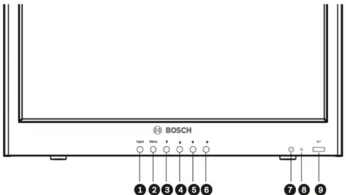
Figure 2.1 Front Panel UML-202

Figure 2.2 Front Panel UML-172 and UML-192
| Number | Button Description | ||
| 1 Input Button Selects the signal to be displayed | |||
| 2 Menu Button Selects the on-screen display (OSD) | |||
| 3 | ▲ | Adjusts the value when in the OSD | Scrolls up in the OSD |
| 4▼ | Adjusts the value when in the OSD or auto adjusts when in PC mode | Scrolls down in the OSD | |
| 5 | Decreases the value when in the OSD | Scrolls left in the OSD | |
| 6 | Increases the value when in the OSD | Scrolls right in the OSD | |
| 7 IR Sensor Remote control sensor | |||
| 8 LED Indicator Power On (green)Power Off, Standby (red) | |||
| 9 Power Button Display Power (On/Off) | |||


Figure 2.3 Side and Bottom Panels
| Side Panel Bottom Panel | |
| Number | Connector Number Connector |
| 1 Video 1 (AV1) IN 12 HDMI IN | |
| 2 Video 1 (AV1) OUT 13 DVI IN | |
| 3 Video 2 (AV2) IN 14 D-SUB IN | |
| 4 Video 2 (AV2) OUT 15 PC Stereo IN | |
| 5 S-Video (Y/C) IN 16 Audio OUT | |
| 6 S-Video (Y/C) OUT 17 Component | |
| 7 Audio IN (AV1, S-Video) | |
| 8 Audio OUT (AV1, S-Video) | |
| 9 Audio IN (AV2) | |
| 10 | Audio OUT (AV2) |
| 11 | 12 V Adaptor |
| Y, Pb, Pr and Sound L, R | |
| 18 DC 12 V IN | |
| 19 Trigger Input | |
2.3 Remote Control
This section details the functions and the usage of the Bosch remote control.
| Button Function | |
| POWER Turns the power ON and OFF. | |
| SOURCE Selects the PC or Video source. | |
| Numbers Numerals 0-9. | |
| AUTO Auto adjusts to the graphics adaptor. | |
| MUTE Mutes the sound. | |
| MENU | Displays the OSD. Pressing the Menu button returns you to the Main menu from anywhere in the OSD menus. |
| EXIT Exits the OSD. | |
| UP Moves the cursor up in an OSD menu. | |
| DOWN Moves the cursor down in an OSD menu. | |
| ENTER Accepts your selection or displays the current mode when in the OSD menu. | |
| VOL | Moves the cursor left, decreases item values in an OSD menu, or decreases sound. |
| VOL | Moves the cursor right, increases item values in an OSD menu, or decreases sound. |
| INFO | Displays the information for the settings currently selected for CVBS or PC Input. |
| STILL Freezes the video by pressing the button once and releases the freeze by pushing it again. | |
| PIP | Activates/deactivates Picture-In-Picture mode. |
| P. INPUT | Selects the PC or Video source for the PIP. Continuously press this button to change the selection. |
| P. POS | Moves the position of the sub picture for the PIP mode. Continuously press this button to change the selection. |
| P. SIZE | Changes the size of the sub and main picture for the PIP mode. Continuously press this button to change the selection. |
| SWAP | Alternates between the main and sub picture for the PIP mode. Continuously press this button to change the selection. |
| ARC (Aspect Ratio Control) | Selects the screen ratio when in Video mode. Continuously press this button to change the selection. |
| APC (Auto Picture Control) | Selects the Picture mode. Continuously press this button to change the selection. |
| ACC (Auto Color Control) | Selects theColormode. Continuously press this button to change the selection. |
| S. SET | Selects theSoundmode main input or sub input (only available when PIP is enabled). |
| PC | Selects thePCmode (HDMI, DVI, PC). Continuously press this button to change the selection. |
| AV | Selects theAVmode (AV1, AV2, S-Video). Continuously press this button to change the selection. |
| COMP Selects the | COMPONENTmode. |
2.4 Remote Control Battery Installation
- Turn the remote over (buttons facing down) and push down on the cover and slide it off.
- Insert two (2) new AAA alkaline batteries, matching the batteries to the (+) and (-) marks inside the battery case.

Figure 2.4 Remote Control Battery Placement
- Slide the battery cover back into place.
Note: Replace batteries when required or at least once a year. Dispose of used batteries properly.
3 Description
The Bosch High Performance Family of LCD monitors display PAL or NTSC standard color pictures in CCTV systems. Two (2) looping Composite Video BNC connector inputs, two (2) looping Audio input RCA, and two (2) looping Y/C (S-Video) inputs using a 4-pin mini-DIN are included. In addition, each model includes an Analog VGA input using 15-pin D-sub to accommodate the increasing use of PCs and digital video devices in security applications, an HDMI (High Definition Multimedia Input), DVI, PC-RGB (VGA), RC Audio In and Out, and Component Video (Y/Pb/Pr) connectors.
Monitor control functions are accessed via the front panel push buttons and On-screen Display (OSD). See Section 2.2 Exploded View, Page 14, for front panel descriptions.
3.1 Features
- 17-inch, 19-inch, and 20-inch models
- 90 to 256 VAC Power Supply
- NTSC/PAL Auto-Detect
– High-Resolution Display - 1024 x 768 (UML-172-90)
- 1280 x 1024 (UML-192-90)
- 1600 x 1200 (UML-202-90)
- V G A I n p u t
- Composite Video Input
- Y/C Input (S-Video)
- On-screen Display (OSD) with Multiple Languages
3.2 Power
| Model No. | Rated Voltage Voltage | Range Power | at Rated Voltage Sync Format | |
| UML-172-90 1 | 20/230 VAC50/60 Hz | 100 to 240 V | < 40 W NTSC/PAL | |
| UML-192-90 1 | 20/230 VAC50/60 Hz | 100 to 240 V < 4 | 5 W NTSC/PAL | |
| UML-202-90 1 | 20/230 VAC50/60 Hz | 90 to 256 V 70 W | (max) NTSC/PAL | |
4 Installing the Monitor
This chapter outlines the procedures to install the UML-172-90, UML-192-90, or the UML-202-90 Series. A qualified service person should install the monitor and adhere to all local codes.
4.1 Ventilation
To prevent overheating, ensure that the ventilation openings on the rear of the monitor are not covered.
4.2 Mounting the Monitor
The UML-172-90, UML-192-90, and the UML-202-90 are designed for use on a desktop or mounted to a wall or rack.
4.2.1 Desktop Installation
The Bosch High Performance monitors are delivered with a 3-pole US-style power cord and a 3-pole Euro-style power cord. Use the US-style power cord where 120 VAC, 60 Hz power is available; use the Euro-style power cord where 230 VAC, 50 Hz power is available. The monitor automatically adjusts to either power input voltage. The viewing angle of the LCD can be adjusted to fit the most comfortable monitoring status.

| Min Degree Max Degree | |
| 25° 122 mm 50° | 192 mm |

NOTICE! For the best viewing quality and holding support, the suggested bracket angle is 25° to 50° .
4.2.2 Wall Mount Installation
The square mounting holes (100 mm [3.9 in.] centers) are compatible with the Bosch UMM-LW-20B fixed wall mount or the UMM-LW-30B swivel/tilt mount.

Figure 4.1 Mounting the Device
4.3 Connecting the Composite Video Signal to the Monitor
There are two (2) BNC connectors located on the rear side panel of the monitor for composite video input and two (2) BNC connectors for composite video outputs (see Figure 2.3).
Note: All video inputs are passive loop-through. The impedance is automatically set to 75 ohm by the input of the signal on the input connector, while operating in a single connection mode (see Figure 4.7). If a cable is also connected to the output connector, the video signal can be passed on to another monitor connected to it via the passive loop-through function. Up to three (3) monitors may be connected in this manner (see Figure 4.8).
Note: To select between AV1 and AV2, press Input (see
Figure 2.1, Item 1 or Figure 2.2, Item 1) located on the front of the monitor.
4.4 Connecting the Y/C (S-Video) Signal to the Monitor
There is one (1) mini-DIN type connector for the S-Video (Y/C) input (see Figure 4.2) on the rear side panel.
Note: Both Y and C inputs are terminated with 75 Ω resistors.

Figure 4.2 Y/C Connection Pinout
| Number | Input |
| 1 | GND |
| 2 | GND |
| 3 Y-signal | IN or OUT |
| 4 C-signal | IN or OUT |
4.5 Connecting Audio to the Monitor
There are two (2) sets of mono audio connectors for audio input, located at the side panel.
- All audio inputs are active loop-through.
- Audio 1 is associated with Video 1 or Y/C; Audio 2 is associated with Video 2.
| Input Audio 1 | Audio 2 | |
| Video 1 | X | |
| Video 2 | X | |
| S-video | X |
4.5.1 Connecting PC Audio
The rear bottom panel has PC stereo audio IN and audio OUT. Connect with 1/8 in. mini phono plug jack to Audio IN.
4.6 Connecting the PC Signal to the Monitor
There are three ways to connect the PC signal to the monitor; HDMI, DVI, and VGA.
4.6.1 HDMI
The monitor can be connected to the HDMI (High Definition Multimedia Input) by connecting a HDMI cable (not supplied).

Figure 4.3 HDMI Input
4.6.2 DVI
The monitor can be connected by using the supplied DVI-D cable and connecting it to the digital DVI-D signal.

Figure 4.4 DVI Input
4.6.3 VGA
The monitor can be connected by connecting the analog VGA signal by using the provided VGA cable (D-SUB to D-SUB).

Figure 4.5 VGA Input
| Pin Description Pin Description | |||
| 1 | R e d V i | d | e o 9 N / A |
| 2 | Green Video | 10 | Signal Cable Detect |
| 3 | Blue Video | 11 | Ground |
| 4 | Ground | 12 | SDA (for DDC) |
| 5 | Ground | 13 | H-Sync or H+V Sync |
| 6 | Red Ground | 14 | V-Synch |
| 7 | Green Ground | 15 | SCL (for DDC) |
| 8 | B l u e G | r | o u nd |
4.7 Connecting an Alarm Trigger
The monitor contains an alarm Trigger Input, the right-most input on the back panel, and an alarm relay cable. These components allow you to connect an alarm relay from a device, such as a camera or a door. Connect the two flying leads from the alarm relay cable into the relay out ports of the device. Then, route the other end of the cable to the Trigger Input connector on the back panel of the monitor.
The following illustration depicts a typical alarm relay configuration:

Figure 4.6 Camera to Monitor Alarm Relay
| Number | Description |
| 1 | Dinion Camera |
| 2 | Flying leads connected to relay outputs 3 and 4 |
| 3 | UML Back Panel |
In the above example, the flying leads of the alarm relay cable are connected to relay output three and four of a Dinion camera. The cable is routed to the back panel of the UML monitor and the plug-end of the wire is connected to the Trigger Input port. See Section 5.7.1 Configuring Alarm Relay Inputs, Page 37, for configuring alarm acknowledgement.
Example: Typical Alarm Trigger Configuration
In this case, the Dinion camera is used to watch for motion. When the camera detects motion it sends an alarm to the UML monitor. The monitor, then, switches the input to display the video from the Dinion camera and sounds a buzzer.
-
Route the coax cable from the Dinion Video output to the AV1 input of the UML monitor.
-
Configure the following settings for the Dinion camera:
- VMD: OSD - A r e a : 1 - Active: On
-
Connect one flying lead to relay output three, on the back of the Dinion camera, and connect the other to relay output four.
-
Connect the other end of the Trigger Relay cable to the Trigger Input connector on the back of the monitor.
-
Plug the monitor into a power socket; then press the Power button.
-
On the monitor, access the Trigger menu:
a. Press the Menu button. b. Press the Down Arrow button to access the Setup menu. c. Press the Right Arrow button to enter the Setup menu. d. Press the Down Arrow button until Trigger is highlighted; then press the Right Arrow button.
- Make the necessary changes to the Trigger menu so that the settings match the following:

- Press the Menu button three (3) times to exit the menu and to return to the video display.
4.8 Single / Multiple Monitor Configuration

Figure 4.7 Single Monitor Configuration
| Number | Description |
| 1 | V i d |
| 2 VIDEO 2 (AV2) IN | |
| 3 VIDEO 2 (AV2) OUT | |
| 4 | VCR |
e o C a
![graph TD A["①"] --> B["②"] B --> C["③"] C --> D["④"] D --> E["⑤"] E --> F["⑥"] F --> G["⑦"] G --> H["⑧"] style A fill:#f9f,stroke:#333 style B fill:#ccf,stroke:#333 style C fill:#cfc,stroke:#333 style D fill:#fcc,stroke:#333 style E fill:#cff,stroke:#333 style F fill:#ffc,stroke:#333 style G fill:#c…](/content/2026/07/1505856/images/2ecbfac6e014c6a5dd889a7438d149c9c601a64b09173c6140a315bcc8e7f5da.jpg)
Figure 4.8 Multiple Monitor Configuration
| Number Description | |||
| 1 | V | i | d e |
| 2 VIDEO 2 (AV2) IN | |||
| 3 VIDEO 2 (AV2) OUT | |||
o C a
5 Navigating the Monitor
5.1 Navigating the Front Panel
Use the front panel to make any necessary OSD adjustments to the UML-172-90, UML-192-90, or to the UML-202-90. See the figure below for an explanation of the front panel.

Figure 5.1 Front Panel Buttons
| Number Button Description | |||
| 1 Input Button Selects the signal to be displayed | |||
| 2 Menu Button Selects the on-screen display (OSD) | |||
| 3 ▲ | Scrolls up in the OSD | ||
| 4 ▼ | Performs an Autoset when connected to the VGA input, which automatically adjusts the display to match the graphics adapter. | Scrolls down in the OSD | |
| 5 | ◀ | Decreases the value | Scrolls left in the OSD |
| 6 | ▶ | Increases the value | Scrolls right in the OSD |
| 7 IR Sensor Remote control sensor | |||
| 8 LED Indicator Power On (green)Power Off, Standby (red) | |||
| 9 Power Button Display Power (On/Off) | |||
5.2 Navigating the Monitor On-screen Display (OSD)
The UML172-90, UML-192-90, and the UML-202-90 have two (2) modes: Video and PC. The LCD is programmed through the on-screen display (OSD) menus and submenus where an operator can select operating parameters. To access the OSD menus, press the Menu button on the front panel or on the remote
control. Use the front panel of the monitor or respective remote control to make any necessary adjustments to the OSD.

NOTICE! When you are navigating through the OSD menus, use the Input button to select a menu and use the Menu button to exit a menu.
To navigate the set up menus, follow the steps below:
- Connect the CVBS or VGA cable.
- If required, press the Input button until a signal is displayed. NOTE: Menus are not available without a signal applied.
- Press the Power button to turn on the unit (see Figure 2.1 or Figure 2.2).
-
Press the Menu button to activate the main menu selections (see Figure 2.1 or Figure 2.2).
-
Press the ▲ and ▼ buttons to select a menu.
-
Press the Input button to enter the selected menu.
-
Press the ◀ and ▶ buttons to select a sub-menu item.
-
Press the ▲ and ▼ buttons to toggle the OSD values.
-
Press the Menu button to exit the selected menu and to return to the menu bar or to confirm a selection.
-
Press the Menu button again to exit the OSD menu bar.
5.3 On-screen Display Menus
There are four (4) on-screen menus that allow you to customize your settings. Press the Menu button to access the OSD menu.
| Icon Menu Function | ||
 | Custom Adjusts the Brightness, Contrast, Color, Tint, and the Sharpness level for video performance of the OSD. (The menu options differ between the Video and PC modes.) | |
 | Picture / Sound Adjusts the Picture Mode, Color Tone, Mute, Volume, Size, and the PC settings. (The menu options differ between the Video and PC modes.) | |
 | PIP Adjusts the Input Source, Size, Position, Swap, and the Sound Select settings. | |
 | Set Up Enables user to Reset the factory default settings and to adjust the Language, OSD Tone, Blue Screen, Key Lock, Trigger, and Auto Switching settings. | |
5.4 Custom Menu
To access the Custom menu, press the Menu button on the front panel of the monitor. Next, press the right arrow and then press the up and down arrows to select a submenu. Press the left and right arrow buttons to increase or decrease the values. When finished, press the Menu button to save any changes, then press the Menu button again to exit the OSD.

Table 5.1 Custom Menu (Video Mode)

Table 5.2 Custom Menu (PC Mode)
| Submenu Definition | |
| Brightness Adjusts the brightness level for video performance (range 0-100). | |
| Contrast Adjusts the contrast level for video performance (range 0-100). | |
| Color Adjusts the overall intensity of the screen (range 0-100). | |
| Tint | Adjusts the tint of the picture (range 0-100). NTSC only. |
| Sharpness | Adjusts the sharpness level for video performance (range 0-100). |
| Phase (Component only) | |
5.5 Picture / Sound Menu
To access the Picture / Sound menu, press the Menu button on the front panel of the monitor, then press the left and right arrows to select the Picture / Sound icon. Press the up and down arrows to select the Picture / Sound submenu.

Table 5.3 Picture / Sound Menu (Video Mode)

Table 5.4 Picture / Sound Menu (PC Mode)
| Submenu Definition | |
| Picture Mode(Video Mode) | Selects the automatic picture control mode. Choices are:Custom:User selected values of the Custom menu are applied.Dynamic:Automatically adjusts the Brightness, Contrast, and Sharpness, maximizing the video quality in the picture.Standard:Applies factory default values. |
| Picture Mode (PC Mode) | Selects the automatic picture control mode. Choices are:Custom:User selected values of the Custom menu are applied.High:Uses the following values: Brightness = 70, Contrast = 80Middle:Uses the following values: Brightness = 60, Contrast = 70.Low:Uses the following values: Brightness = 50, Contrast = 60. |
| Color Tone Selects the color temperature. Choices are: Cool 9300K, Normal 6500K, Warm 5000K. | |
| Mute Enables/disables audio. Choices are: On and Off. | |
| Volume Controls built-in speaker output volume (range 0-100). | |
| Size (Video Mode) | Selects the Aspect Ratio Control mode. Choices are: 4:3, Panorama, Zoom1, Zoom2, Wide. |
| DNR (Video Mode) Turns Noise Reduction On or Off. Turning this feature OFF reduces the video quality slightly, but improves the monitors response time to MOTION. | |
| PC (PC Mode) Selects between Auto or manual adjustment of the desktop screen. Auto Adjust: Auto synchronizes screen to graphics adaptor.Manual choices are: Phase (range 0-100), H-Position (range 0-100), V-Position (range 0-100), Frequency (range 0-100). | |
| 3D Comb Activates the 3D comb filter. | |
5.6 PIP Menu
To access the PIP menu, press the Menu button on the front panel of the monitor, then press the left and right arrows to select the PIP icon. Press the up and down arrows to select the PIP submenu.

Table 5.5 PIP menu
| Submenu Definition | |
| PIP | Activates the PIP feature. |
| Input Source S | select the video input source for the PIP area. The selections depend on the main video input source. Analog video sources (AV1, AV2, S-Video) can display only digital video (Component, HDMI, DVI, PC) inputs in the PIP area; digital video sources can only display analog video inputs in the PIP area.AV1, AV2, S-Video: Component, HDMI, DVI, PCComponent, HDMI, DVI, PC: AV1, AV2, S-Video |
| Size Enables 3 | screen sizes: full screen side by side, 4:3 side by side, and 4:3 corner (177 mm [3.03 in.] diagonal). |
| Position | Enables 4 positions: bottom right, top right, bottom left, top left. |
| Swap | Alternates between the main and sub picture for the PIP mode.Continuously press to change selection. |
| Sound Select | Select the sound source from either the Main or the PIP input source (only available when PIP is enabled). |
5.7 Setup Menu
To access the Setup menu, press the Menu button on the front panel of the monitor, then press the left and right arrows to select the Setup icon. Press the up and down arrows to select the Setup submenu.

Table 5.6 Setup Menu
| Submenu | Definition |
| Reset | Restores default settings. |
| Language | Adjusts the language of the OSD. Choices are: English, French, German, Italian, Dutch, Spanish, and Portuguese. |
| OSD Tones | Selects the type of background for the OSD menu. Choices are: Transparency and Blue. |
| Blue Screen | Enables or disables video loss indication. Choices are: On: displays a blue background when video loss is detected. Off: displays a black background when video loss is detected. |
| Key Lock | Enables or disables the Key Lock function. |
| Trigger | Opens the Trigger menu allowing you to configure the monitor's repsonse to incoming alarms. See Section 5.7.1 Configuring Alarm Relay Inputs, Page 37. |
| Auto Switching | Opens the Auto Switching menu allowing you to configure the way the monitor cycles through video inputs. See Section 5.7.2 Configuring Auto Switching, Page 39. |
| Firmware Version | Displays the release level of the monitor firmware. |

NOTICE! When key lock is enabled through the front panel, use either the remote control or the front panel buttons to disable the key lock command. To disable the key lock feature using the front panel buttons, press and hold both the Input and the Menu buttons until the monitor displays the Key Unlocked message.
5.7.1 Configuring Alarm Relay Inputs
The monitor allows you to connect an alarm relay cable from a device (camera or door) to the monitor, and then to configure the monitor's response to an incoming alarm (see Section 4.7 Connecting an Alarm Trigger, Page 25).
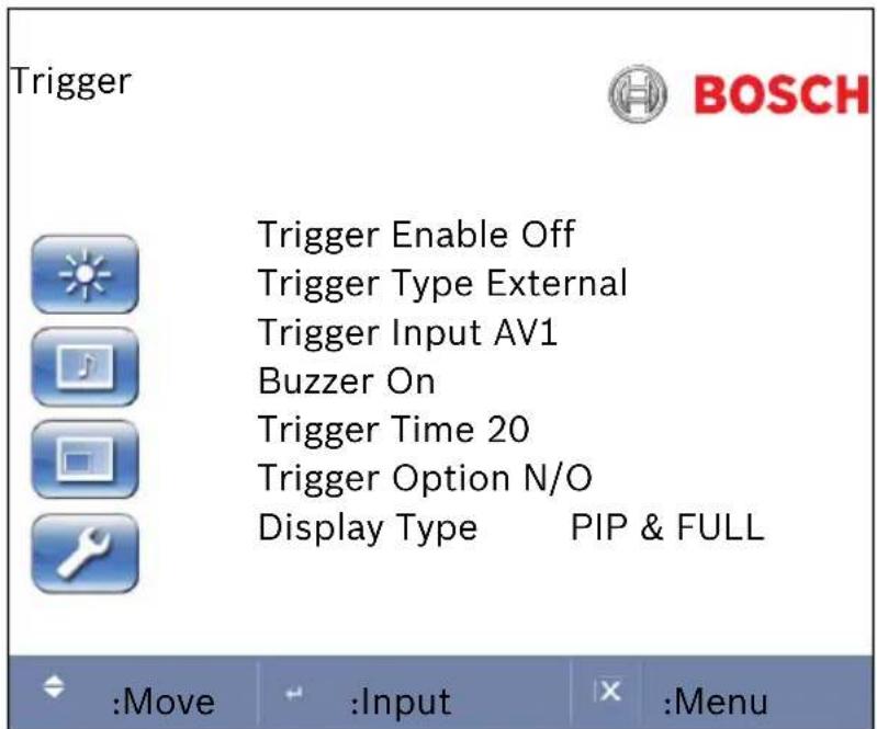
Table 5.7 Trigger Menu
| Option | Definition | Selections |
| Trigger Enable | Activates the trigger feature. | ON or OFF |
| Trigger Type | Specifies the source of the alarm. This option is always set to External. | External |
| Option Definition Selections | |
| Trigger Input Select the video input source that the monitor displays when an alarm is activated. When the monitor receives an alarm input, it switches to the specified input source. | AV1AV2S-VideoComponentHDMIDVIPC |
| Buzzer Activates an audible signal when the monitor receives an alarm input and switches to the Trigger Input video source.Note: If the Input video source is the same as the Trigger Input, the monitor does not sound the buzzer. | ON or OFF |
| Trigger Time Select the amount of time, in seconds, that the monitor displays the Trigger Input video source. | 0-100 seconds |
| Trigger Option Select the type of physical trigger input. Consult the manual for the alarm source to determine your selection. | N/C (normally closed)N/O (normally open)High (2-5 V)Low (< .6 V) |
| Display Type Select the mode in which the monitor displays the Trigger Input. The monitor takes one of the following actions:- Displays the Trigger Input in the Picture-in-Picture position (PIP & FULL) of the current video input source.Note: The main video source must support the Trigger Input source as a PIP option. See Section 5.6 PIP Menu, Page 35.- Switches the display to show the Trigger Input in the full screen (FULL). | PIP & FULLFULL |
5.7.2 Configuring Auto Switching
The Auto Switching feature allows the monitor to cycle the display of selected video inputs.

Table 5.8 Auto Switching Menu
| Option Definition Selections | ||
| Auto Swtiching | Activates the Auto Switching feature. | ON or OFF |
| Input | Opens another menu in which you select the input sources to include in the Auto Switching cycle. | |
| Time | Select the amount of time, in seconds, that the monitor displays each selected input source. | 0-100 seconds |
Selecting Input Sources for Auto Switching
Use this menu to add or remove an input source from the Auto Switching cycle.

Table 5.9 Auto Switching Menu – Input Source Selection
- Use the Up and Down arrow buttons to select an input source.
- Press the Right Arrow to change the status of the input source.
- Use the Up and Down arrow buttons to change the status of the input source:
- Select On to include the input source in the cycle.
- Select OFF to remove the input source from the cycle.
6 Power Management
These monitors feature a power management system to “power down” upon receipt of the display power management signaling (DPMS) from a DPMS video card.
The DPMS-compliant video card performs this signaling system by not sending a horizontal, vertical, or a sync signal.
The monitor enters an appropriate mode through identifying each of the three (3) modes of the signaling system.
6.1 Power Consumption
| Mode Power Consumption | |
| ON 70 W | |
| STANDBY 10 W | |
| SUSPEND 10 W | |
| ACTIVE OFF 10 W | |
6.2 LED Indicator
The power management feature of the monitor is comprised of these stages:
| Mode LED | Color | Monitor Operation |
| ON Green Normal operation | ||
| STANDBY FlasheRed | Screen blanks after idle time and some electroniccircuits or all circuitry in the monitor shuts down. | |
| SUSPEND | ||
| ACTIVE OFF | ||
| UNSUPPORTED MODE | Green Normal operation but the screen displays an errormessage. | |
| POWER OFF | Red Not operational. | |
7 Maintenance
To clean the LCD panel, wipe off water droplets or oil immediately with absorbent cotton or a soft lint-free cloth. Staining and discoloration may occur if left on the panel for long periods.
If the surface (polarizer) of the LCD panel is dirty or stained, use absorbent cotton or a soft lint-free cloth to remove the residue as follows:
- Turn off the computer or display.
- Do not spray any liquid directly on the screen. Dampen a clean, soft, lint-free cloth with water only (using a paper towel or dirty cloth can scratch the screen).
- Gently wipe the screen starting from the top of the screen to bottom wiping in a downward motion. Be careful not to press too hard to avoid damaging the screen.
- To avoid streaking, wipe the screen again with another clean, dry, lint-free cloth.

NOTICE! If water does not work, use a mild cleaner labeled for use with LCD panels, available at office supply stores.
Do not use any of the following as a cleaning agent:
- Ketone type materials
- Ethyl alcohol
- Ethyl acid
- T o l u e n e
- Methyl chloride
- A m m o n i a
Use of these materials may permanently damage the polarizer due to a chemical reaction.
8 TroubleShooting Guide
| Problem Solution | |
| No image is displayed on screen | - Check that the power cord of the monitor is securely connected into the wall outlet or grounded extension cable or strip.- Power switch should be in the ON position and the LED lit.- Check that the Brightness and/or Contrast adjustments of the display have not been turned down to minimum levels. |
| “Going to Sleep” message is displayed | - The signal cable should be completely connected to the video card/computer.- The video card should be completely seated in its slot and the computer switched ON. |
| Display image is not centered, is too small, or too large in the PC mode | - Push the down key to activate the Autoset function.-or- -Adjust the Clock and Phase in the PC OSD submenu. |
| Monitor does not switch upon trigger input | Compare the Trigger Option setting on the Trigger menu with the physical alarm output setting for alarm device. |
| Monitor does not sound the buzzer | If the video input and the Trigger Input are from the same source:- Set the Trigger Time to zero (0).If the video input and the Trigger Input are from different sources, check the following settings on the Picture/ Sound menu:- Ensure that the Mute option is set to OFF.- Ensure that the Volume is set to an audible level. |
| Vertical or horizontal noise is present in the picture | - Push the down key to activate the Autoset function (for VGA inputs only). -or- -Adjust the Clock and Phase in the PC OSD submenu. |
| Incorrect colors | - Press the Menu button on the front panel of the monitor, then press the down arrow to select the Color Tone menu. Press the down arrow on the front panel and select Cool, Warm, or Normal. - or - -Press the Menu button on the front panel of the monitor, then press the right arrow to select the Setup menu. Press the down arrow on the front panel and select Recall to reset to the default settings. |
| The error message “Out of Range” is displayed | PC is operating with either a resolution or timing mode that is not supported by the monitor. Change the PC timing mode to one of the valid combinations below: 640 x 480; 60/72/75 Hz 800 x 600; 60/72/75 Hz 1024 x 768; 60/70/75 Hz 1280 x 1024; 60 Hz 1600 x 1200; 60 Hz |
Americas
Bosch Security Systems, Inc.
850 Greenfield Road
Lancaster, Pennsylvania 17601 USA
Telephone +1 888-289-0096
Fax +1 585-223-9180
Email:
security.sales@us.bosch.com
www.boschsecurity.us
Europe, Middle East, Africa: Bosch Security Systems B.V.
P.O. Box 80002
5600 JB Eindhoven,
The Netherlands
Phone: +31 40 2577 284
Fax: +31 40 2577 330
emea.securitysystems@bosch.c
om
www.boschsecurity.com
Asia-Pacific:
Bosch Security Systems Pte Ltd
38C Jalan Pemimpin
Singapore 577180
Phone: +65 6319 3450
Fax: +65 6319 3499
apr.securitysystems@bosch.com
www.boschsecurity.com
© Bosch Security Systems, Inc. 2009; F.01U.076.723 | 3.0 | 2009.03; Data subject to change without notice.

- HIGH PERFORMANCE LCD MONITORS
- TABLE OF CONTENTS
- S A F E T Y
- UNPACKING
- DESCRIPTION
- INSTALLING THE MONITOR
- NAVIGATING THE MONITOR
- POWER MANAGEMENT
- MAINTENANCE
- TROUBLESHOOTING GUIDE
- IMPORTANT SAFETY INSTRUCTIONS
- SAFETY PRECAUTIONS
- IMPORTANT NOTICES
- COAX GROUNDING
- NOTICE
- SELV
- FCC & ICES INFORMATION
- NOTE
- INFORMATIONS FCC ET ICES (COMMERCIAL APPLICATIONS)
- DISCLAIMER
- COPYRIGHT
- TRADEMARKS
- CUSTOMER SUPPORT AND SERVICE
- SERVICE CENTERS
- USA
- REPAIR CENTER
- CUSTOMER SERVICE
- TECHNICAL SUPPORT
- CANADA
- EUROPE, MIDDLE EAST, AFRICA REGION
- ASIA REGION
- WARRANTY AND MORE INFORMATION
- PARTS LIST
- EXPLODED VIEW
- REMOTE CONTROL
- REMOTE CONTROL BATTERY INSTALLATION
- FEATURES
- POWER
- VENTILATION
- MOUNTING THE MONITOR
- DESKTOP INSTALLATION
- WALL MOUNT INSTALLATION
- CONNECTING THE COMPOSITE VIDEO SIGNAL TO THE MONITOR
- CONNECTING THE Y/C (S-VIDEO) SIGNAL TO THE MONITOR
- CONNECTING AUDIO TO THE MONITOR
- CONNECTING PC AUDIO
- CONNECTING THE PC SIGNAL TO THE MONITOR
- HDMI
- DVI
- VGA
- CONNECTING AN ALARM TRIGGER
- EXAMPLE: TYPICAL ALARM TRIGGER CONFIGURATION
- SINGLE / MULTIPLE MONITOR CONFIGURATION
- NAVIGATING THE FRONT PANEL
- NAVIGATING THE MONITOR ON-SCREEN DISPLAY (OSD)
- ON-SCREEN DISPLAY MENUS
- CUSTOM MENU
- PICTURE / SOUND MENU
- PIP MENU
- SETUP MENU
- CONFIGURING ALARM RELAY INPUTS
- CONFIGURING AUTO SWITCHING
- SELECTING INPUT SOURCES FOR AUTO SWITCHING
- POWER CONSUMPTION
- LED INDICATOR
- AMERICAS
- BOSCH SECURITY SYSTEMS, INC
- EUROPE, MIDDLE EAST, AFRICA: BOSCH SECURITY SYSTEMS B.V
- ASIA-PACIFIC
- BOSCH SECURITY SYSTEMS PTE LTD
Brand : BOSCH
Model : UML19290
Category : Monitor