
HVR-S270N - Camcorder SONY - Free user manual and instructions
Find the device manual for free HVR-S270N SONY in PDF.


| Type of product | Professional HDV Camcorder |
| Model | HVR-S270N |
| Brand | Sony |
| Imaging system | 3CCD (1/3-inch) with Exmor CMOS |
| Recording format | HDV 1080i (MPEG-2) / DV (SP/LP) |
| Lens mount | 1/3-inch bayonet (interchangeable lens compatible) |
| LCD monitor | 3.5-inch (approx. 921K dots) |
| Dimensions (W x H x D) | Approx. 200 x 269 x 407 mm (with standard lens) |
| Weight | Approx. 3.2 kg (body only), approx. 4.5 kg with lens and battery |
| Power supply | DC 12V (via AC-L100A AC adapter) or Battery (NP-F970) |
| Power consumption | Approx. 15W (recording mode) |
| Recording media | MiniDV tape (HDV/DV) |
| Recording time | HDV: up to 63 min (with standard tape), DV: up to 41 min (SP) / 83 min (LP) |
| Video signal | 1080i (60i/50i), switchable |
| Audio | Dolby Digital (2ch) / PCM (2ch) |
| White balance | Auto, preset (indoor, outdoor, manual) |
| Built-in ND filter | OFF, 1/4, 1/16, 1/64 |
| Input/Output | HDV/DV i.LINK (FireWire), Composite, S-Video, Audio, Headphone, LANC |
| Maintenance | Clean lens with soft cloth; avoid dust; periodic head cleaning recommended |
| Safety | Do not expose to rain or moisture; use only specified battery and charger |
| Spare parts / repairability | Consult authorized Sony service center; limited availability of parts |
Frequently Asked Questions - HVR-S270N SONY
User questions about HVR-S270N SONY
0 question about this device. Answer the ones you know or ask your own.
Ask a new question about this device
Download the instructions for your Camcorder in PDF format for free! Find your manual HVR-S270N - SONY and take your electronic device back in hand. On this page are published all the documents necessary for the use of your device. HVR-S270N by SONY.
USER MANUAL HVR-S270N SONY
Before operating the unit, please read this manual thoroughly, and retain it for future reference
HDV
HDV 1080i
PROGRESSIVE
DVCAM
MENORY STICK TM
DV Digital Video Cassette
Mini Digital Video Cassette
http://www.sony.net/

Printed on 70% or more recycled paper using VOC (Volatile Organic Compound) -free vegetable oil based ink.
Printed in Japan

HVR-S270U/S270N
© 2008 Sony Corporation
Read this first
Before operating this unit, please read this manual thoroughly, and retain it for future reference.
Notes on use
Types of cassette you can use in your camcorder
Your camcorder is capable of recording in HDV, DVCAM and DV formats.
When recording in HDV/DV format, Sony recommends that you use standard size DV cassettes or mini DV cassettes.
When recording in DVCAM format, Sony recommends that you use standard size DVCAM cassettes or mini DVCAM cassettes. Your camcorder does not support the Cassette Memory function (p. 107).
The HDV format
- Digital high-definition (HD) video signals are recorded and played back on a DV format cassette.
- HDV signals are compressed in MPEG2 format, which is adopted in BS (broadcast satellite) digital and terrestrial digital HDTV broadcastings and in Blu-ray disc recorders.
Types of "Memory Stick" you can use in your camcorder
You can use any "Memory Stick" that has the following markings.
MEMORY STICK DUO MEMORY STICK PRO DUO MEMORY STICK PRO · HG DUO
"Memory Stick Duo"
(This size can be used with your camcorder.)

"Memory Stick"
(You cannot use it in your camcorder.)

Notes
- You cannot use any type of memory card except “Memory Stick Duo.”
- “Memory Stick PRO Duo” can be used only with “Memory Stick PRO” compatible equipment.
- Do not attach a label or the like on a "Memory Stick Duo" or a Memory Stick Duo Adaptor.
- When using a “Memory Stick Duo” with “Memory Stick” compatible equipment, insert the “Memory Stick Duo” into the Memory Stick Duo Adaptor.
Using the camcorder
- Do not hold the camcorder by the following part.

Lens hood

LCD panel

Battery pack

Microphone or Microphone holder

Viewfinder

Memory Recording Unit
Notes
- The camcorder is not dustproof, dripproof or waterproof.
See “About handling of your camcorder” (p. 113).
- Do not connect cables to your camcorder with their terminals placed the wrong way. Squeezing the terminals into your camcorder's jacks may damage them or results in a malfunction of your camcorder.
About menu items, LCD panel, viewfinder, and lens
- A menu item that is grayed out is not available under the current recording or playback conditions.
- The LCD screen and the viewfinder are manufactured using extremely high-precision technology, so over 99.99% of the pixels are operational for effective use. However, there may be some tiny black points and/or bright points (white, red, blue, or green in color) that appear constantly on the LCD screen and the viewfinder. These points are normal results of the manufacturing process and do not affect the recording in any way.

Do not expose your camcorder's viewfinder, lens, or LCD screen to the sun or strong light source for extended periods.
- Intense light sources, especially the sun will converge on the viewfinder or lens and damage the internal parts of your camcorder. Avoid sunlight or other strong light sources when storing your camcorder. Protect this device by always closing the lens cover or by placing it in its bag when not in use.
On recording
- Before starting to record, test the recording function to make sure the picture and sound are recorded without any problems.
Read this first (Continued)
- Compensation for the contents of recordings cannot be provided, even if recording or playback is not possible due to a malfunction of the camcorder, storage media, etc.
- TV color systems differ depending on the countries/regions. To view your recordings on a TV, you need an NTSC system-based TV.
- Television programs, films, video tapes, and other materials may be copyrighted. Unauthorized recording of such materials may be contrary to the copyright laws.
- Because of the way that the image device (CMOS sensor) reads out image signals, the subjects passing by the frame rapidly might appear crooked depending on the recording conditions. This phenomenon may be notable in displays having high motion resolution.
On playing back HDV tapes on other devices
A tape recorded in the HDV format cannot be played back on a device that is not compatible with the HDV format. Check the contents of tapes by playing them back on this camcorder prior to playing them back on other devices.
Notes on the icons used in this manual
HDV1080i Features available for the HDV format only.
DVCAM Features available for the DVCAM format only.
DV SP Features available for the DV SP format only.
i.LINK The function that can be used when i.LINK cable is connected.
AS The function that can be assigned to an ASSIGN button.
About this manual
- The images of the LCD screen and the viewfinder used in this manual for illustration purposes are captured using a digital still camera, and therefore may appear different.
- The on-screen displays in each local language are used for illustrating the operating procedures. Change the screen language before using your camcorder if necessary (p. 21).
- Design and specifications of recording media and other accessories are subject to change without notice.
About the Carl Zeiss lens
Your camcorder is equipped with a Carl Zeiss lens, which was developed jointly by Carl Zeiss, in Germany, and Sony Corporation, and produces superior images. It adopts the MTF measurement system for video cameras and offers a quality typical of a Carl Zeiss lens. Also, the lens for your camcorder is T*coated to suppress unwanted reflections and faithfully reproduce colors.
MTF= Modulation Transfer Function. The number value indicates the amount of light from a subject coming into the lens.
Table of Contents
Read this first 2
Getting Started
Step 1: Checking supplied items ....8
Step 2: Attaching the supplied items .....9
Step 3: Preparing a power supply ....15
Step 4: Turning the power on and holding your camcorder properly .....17
Step 5: Adjusting the viewfinder and LCD panel .....18
Step 6: Setting the date and time ....20
Step 7: Inserting a tape or a "Memory Stick Duo" ....22

Recording/Playback
Recording 25
Changing the settings of your camcorder recordings ....29
Adjusting the zoom 29
Adjusting the focus manually.... 30
Adjusting the exposure 32
Adjusting to natural color (White balance).... 34
Adjusting the black balance 36
Customizing the picture quality (Picture profile) 36
Adjusting the volume 45
Assigning the functions to the ASSIGN buttons ....48
Recording an index signal 49
Reviewing the most recently recorded scenes (Rec review).... 50
Searching for the last scene of the most recent recording (End search) 50
Playing back the most recently recorded movies (Last scene review).... 50
Using the Shot transition ....51
Marking focal point on the screen (Focus marking) ....54
Playback ....55
Changing/checking the settings in your camcorder ....58
Changing the screen 58
Displaying recording data (Data code) 58
Displaying the settings in your camcorder (Status check) 59
Connecting a monitor or a TV 60
Using the Menu
Using the menu items 62
Menu items 64

(CAMERA SET) menu 67
Settings to adjust your camcorder to the recording conditions (GAIN SETUP/BACK LIGHT/STEADYSHOT, etc.)

(AUDIO SET) menu 74
Settings for the audio recording (HDV 2CH/4CH/XLR SET, etc.)

(DISPLAY SET) menu 76
Display settings of the display and the viewfinder (MARKER/VF B.LIGHT/DISP OUTPUT, etc.)

(IN/OUT REC) menu 80
Recording settings, input and output settings (REC FORMAT/HDV PROGRE./VIDEO OUT/EXT REC CTRL, etc.)

(TC/UB SET) menu 85
(TC PRESET/UB PRESET/TC LINK, etc.)

(MEMORY SET) menu 87
Settings for the "Memory Stick Duo" (ALL ERASE/FORMAT, etc.)

(OTHERS) menu 88
Settings while recording on a tape or other basic settings (QUICK REC/BEEP, etc.)
Dubbing/Editing
Recording pictures from a VCR 92
Copying movies on a tape to a computer 94
Troubleshooting
Troubleshooting 97
Warning indicators and messages 106
Additional Information
Maintenance and precautions 107
HDV format and recording/playback 107
Compatibility of the DVCAM/DV formats.... 108
About the "Memory Stick" 110
About i.LINK 111
About x.v.Color 112
About handling of your camcorder 113
Specifications 117
Quick Reference
Identifying parts and controls 121
Indicators for the LCD screen and viewfinder 128
Index 132
Getting Started
Step 1: Checking supplied items
Make sure that you have following items supplied with your camcorder.
The number in the parentheses indicates the number of that item supplied.
- A cassette tape and a “Memory Stick Duo” are not included. See pages 2, 107 and 110 for types of cassette tape and “Memory Stick Duo” that you can use on your camcorder.
Carl Zeiss lens (VCL-412BWS) (1) (p. 9) This lens is pre-mounted.
Memory Recording Unit (HVR-MRC1) (1) (p. 13),

i.LINK Cradle (HVRA-CR1) (1) (p. 14)

Lens hood with lens cover (1) (p. 11) This lens hood is pre-mounted.

Large eyecup (1) (p. 18)

Wind Screen (1), Microphone (ECM-XM1) (1) (p. 11)

Accessory shoe kit (Accessory shoe (1), Accessory shoe plate (1), screws (4)) (p. 121)

Shoulder belt (1) (p. 12)
Lens mount cap (1) (p. 127), Rear lens cap (1) (p. 127)
Test chart for flange focal length adjustment (1) (p. 9)
CD-ROM "Manuals for Digital HD Video Camera Recorder" (1)
Operating Guide (This manual) (1)
Step 2: Attaching the supplied items
Mounting the lens
Make sure to turn off the POWER switch of your camcorder before mounting the lens. Refer to the manuals provided with the lens for details on the proper handling of the lens.

Mounting the Carl Zeiss lens
① Push the lens locking lever D up and remove the lens or the lens mount cap from the lens mount.
②Align the center slot in the lens mount with the center pin on the lens, and insert the lens into the mount.
③While holding the lens in place, push the lens locking lever D down to mount the lens.
Notes
- If the lens is not properly locked, it may come off when in use, which may cause a serious problem. Make sure that the lens is securely locked. Sony recommends that you set the lens securing tab as illustrated.
Mounting non-Carl Zeiss lens
① Push the lens locking lever D up and remove the lens or the lens mount cap from the lens mount.
②Align the center slot in the lens mount with the center pin on the lens, and insert the lens into the mount.
③While holding the lens in place, push the lens locking lever D down to mount the lens.
④Connect the lens cable to the LENS jack A.
⑤Push the lens cable in the cable holder B.
Notes
- You can mount a 1/3" lens directly on your camcorder. You can mount a 1/2" lens via the Fujinon ACM-19 or equivalent. You can mount a 2/3" lens via the Fujinon ACM-17 or equivalent.
- If the lens is not properly locked, it may come off when in use, which may cause a serious problem. Make sure that the lens is securely locked. Sony recommends that you set the lens securing tab [C] as illustrated.
- Press the REC START/STOP button on the handle to record when using a lens that does not have a lens cable.
Tips
- When you attach a non-Carl Zeiss lens, Sony recommends that you adjust the black balance with the iris closed before recording. (p. 36)
Adjusting the flange focal length (for Carl Zeiss lens)
You need to adjust the flange focal length (the distance from the lens flange to the plane of the image along the optical axis) in the following cases.
• After you have changed lenses.
- When you cannot adjust focus properly during zoom in or out.
Tips
- Your camcorder can store flange focal length data for ten different Carl Zeiss lenses (VCL-412BWS/VCL-308BWS). If you remount the lens after you have mounted ten different lenses and adjusted their flange focal length, you need to adjust the flange focal length for the lens even for the Carl Zeiss lens whose flange focal length has been adjusted.
Step 2: Attaching the supplied items (Continued)

Adjusting the flange focal length automatically
① Set the ND filter B to 1 to adjust brightness so that the proper video light level is obtained.
②Place the flange focal length adjustment test chart A about 2-3 meters (7-10 feet) away. Zoom in and set your camcorder to locate the center of the chart in the center of the screen.
③ Set the ZOOM switch F to SERVO.
④Select [AUTO ADJUST] in [FLANGE BACK] of the Camera SET menu (p. 73).
⑤Select [YES] with the SEL/PUSH EXEC dial E.
The flange focal length adjustment starts and [EXECUTING] appears on the screen. When the adjustment is completed, [Completed.] appears on the screen. If the adjustment fails, [Could not adjust.] appears on the screen. Try the adjustment again.
Adjusting the flange focal length manually
① Perform steps ① and ② of “Adjusting the flange focal length automatically.”
② Set the ZOOM switch F to MANUAL.
③Select [MANU ADJUST] in [FLANGE BACK] of the (CAMERA SET) menu.
④Select [YES] with the SEL/PUSH EXEC dial E.
⑤ Turn the zoom ring D to the telephoto position.
⑥ Turn the focus ring C until the subject comes in focus, then press the SEL/PUSH EXEC dial E.
⑦ Turn the zoom ring D to the wide angle position.
⑧ Turn the focus ring C until the subject comes in focus, then press the SEL/PUSH EXEC dial E.
When the adjustment is completed, [Completed.] appears on the screen. If the adjustment fails, [Could not adjust.] appears on the screen. Try the adjustment again.
Tips
- You can check the focusing easily if you do the following before adjusting the focal length.
- Set the PEAKING switch to ON (p. 31).
- Press the ASSIGN button to which [EXP.FOCUS] is assigned (p. 48).
Attaching the supplied microphone
![A B C D E F [REC CH SELECT] IN1 IN2 IN3 IN4 CH1 CH2 2CH MODE](/content/2026/07/1523711/images/5bfe542983fe6d2781f54af63530e72ff9a550ff9f817c497398e4476264b9b2.jpg)
1 Attach the wind screen B to the supplied microphone A.
2 Place the microphone A in the microphone holder C with the model name facing upward, close the cover, and shut the clamp.
3 Connect the plug of the microphone to theAUDIO INPUT1 (L) jack D.
4 Put the microphone cable into the cable holder E.
5 Select the channel with the REC CH SELECT switch F.
See p. 45 for details.
Tips
• See page 45 for adjusting the volume.
- Set theINPUT1/2/3/4 switch for the jack connected to the microphone to MIC+48V.
Attaching the lens hood with lens cover

PUSH (lens hood release) button
Align the marks on the lens hood to those on the camcorder, and turn the lens hood in the direction of the arrow ②.
To remove the Lens hood with lens cover
Turn the lens hood in the opposite direction to the arrow ② in the illustration while pressing the PUSH (lens hood release) button.
Step 2: Attaching the supplied items (Continued)

Tips
- If you attach or remove a 72mm (2 7/8 in.) PL filter or MC protector, remove the lens hood with lens cover.
To open or close the shutter of the Lens hood with lens cover
Move the lens cover lever up or down to open or close the lens cover.

Move the lens cover lever to OPEN to open the lens cover, and move the lever to CLOSE to close the lens cover.
Attaching the shoulder strap
1 Fit one of the clips to a shoulder strap fitting.

Pull up the strap to lock the fitting.
2 Fit the other clip to the shoulder strap fitting on the other side of the grip in the same way.

To remove the shoulder strap
Pull in the direction of the arrow while pressing here.


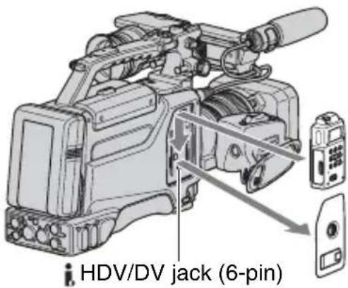
Attaching Memory Recording Unit
Attach the Memory Recording Unit to your camcorder as illustrated.
For details, refer to the Operating Instructions of the Memory Recording Unit on the CD-ROM.
Notes
- You cannot use the i HDV/DV jack when the Memory Recording Unit is attached to your camcorder.
To remove the Memory Recording Unit
Slide the unit upward while pushing the RELEASE lever of the Memory Recording Unit downward.

Step 2: Attaching the supplied items (Continued)
To attach the Memory Recording Unit to the i.LINK Cradle
Attach the Memory Recording Unit to the i.LINK Cradle as illustrated.

To remove the Memory Recording Unit from the i.LINK Cradle
Slide the unit upward while pushing the RELEASE lever of the Memory Recording Unit downward.

Tips
- Refer to the operating instructions of HVR-MRC1 on the supplied CD-ROM for details on the i.LINK Cradle.
Step 3: Preparing a power supply
The following power supplies are recommended for your camcorder.
- BP-GL65/GL95/L60S/L80S Lithium-ion Battery Pack
• AC power using the AC-550, AC-DN2, AC-DN10 AC Adaptor
Using a battery pack
Approximate operating time (min.) when you use a fully charged battery pack.
| Model name HDV DVCAM (DV) |
| BP-GL65 240 255 |
| BP-GL95 370 385 |
| BP-L60S 215 230 |
| BP-L80S 295 310 |
Before use, charge the battery pack with a charger suitable for each battery.
- All times are measured under following conditions.
- when recording on both tape and Memory Recording Unit (HVR-MRC1)
- when using the microphone (ECM-XM1)
- when recording continuously
- when using the viewfinder with the LCD panel closed
- For details on charging procedure, refer to the battery charger operation manual.
Notes
- A warm battery pack may not be able to be fully recharged.
- Set [BATTERY TYPE] to display an accurate battery life (p. 90).
To attach the battery pack
①Press the battery pack against the back of the camcorder, aligning the line on the side of the battery pack with the matching line on the camcorder.

Back of the camcorder
②Slide the battery pack down until its "LOCK" arrow points at the matching line on the camcorder.

To detach the battery pack

Notes
- During recording, playback, and loading/unloading a tape, be careful never to remove the battery pack.
- Make sure to turn the camcorder off before changing the battery (except when using an AC-550 and an AC-DN2/DN10 AC Adaptor together).
Step 3: Preparing a power supply (Continued)
Using an AC Adaptor
To use the AC-550 AC Adaptor
Connect the camcorder to the AC power supply through an AC-550 AC Adaptor as shown in the following figure, and turn the POWER switch of the AC-550 on.

To use the AC-DN10 AC Adaptor
Mount an AC-DN10 on the camcorder in the same way as a battery pack, then connect to the AC power supply.
The AC-DN10 can supply up to 100 W of power.

Avoiding breaks in operation due to an exhausted battery
When the battery pack is becoming exhausted, you can perform battery replacement without causing a break to the camcorder operation by using an AC Adaptor.
①Turn the AC-550 AC Adaptor on.
②Connect an AC-550 AC Adaptor to an AC power source, then connect it to the DC IN 12V connector of the camcorder (p. 16).
The power source switches automatically from the battery pack to the AC Adaptor connected to the DC IN 12V connector.
Notes
• There may be some noise on the video signal at the time of power source switching.
③Replace the battery pack with a fully charged one.
Step 4: Turning the power on and holding your camcorder properly
To record or play, set the CAMERA/VCR switch to respective positions.
When you use your camcorder for the first time, [CLOCK SET] screen appears (p. 20).

1 Set the POWER switch to ON, and set the CAMERA/VCR switch.
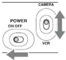
CAMERA: To record pictures.
VCR: To play or edit pictures.
Notes
- The current date and time appears on the LCD screen for a few seconds when you turn on your camcorder once you set the date and time ([CLOCK SET], p. 20).
2 Hold the camcorder properly.

3 Ensure a good grip, then fasten the grip belt.

To turn off the power
Set the POWER switch to OFF.
Notes
- If warning messages appear on the screen, follow the instructions.
Step 5: Adjusting the viewfinder and LCD panel
The viewfinder
To attach the large eyecup
To attach the supplied large eyecup, stretch it slightly and align it with the eyecup groove in the viewfinder. You can attach the large eyecup facing either the right or left side.

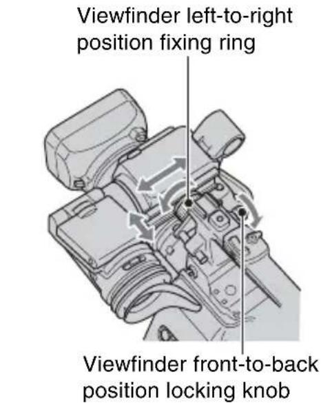
To adjust the viewfinder position
To adjust the viewfinder left-to-right position, loosen the left-to-right fixing ring. To adjust the front-to-back position, loosen the front-to-back position locking knob.
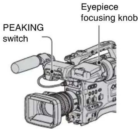
To adjust the eyepiece focus
First focus the image with the lens, then adjust the viewfinder lens adjustment lever to get the clearest viewfinder image for your eyesight.
To adjust the image detail
Set the PEAKING switch to ON. The detail of the viewfinder image is enhanced, which helps you to focus the image.
To adjust the brightness
Set the brightness in [VF B.LIGHT] of

(DISPLAY SET) menu (p. 79).
Notes
- You may see primary colors shimmering in the viewfinder when you move your eye line. This is not a malfunction. The shimmering colors will not be recorded on the recording media.
The LCD panel


Tips
- You can use the LCD panel for recording mirror image. You will see a mirror image on the LCD screen but the image will be recorded in a normal image.
To adjust the brightness
Adjust the LCD brightness with the - LCD BRIGHT + buttons. You can turn on and off the LCD backlight by pressing the DISPLAY button.
Step 6: Setting the date and time
Set the date and time when using this camcorder for the first time. If you do not set the date and time, [CLOCK SET] screen appears every time you turn on your camcorder or change the CAMERA/VCR switch position.

Tips
- If you do not use your camcorder for about 3 months, the built-in rechargeable battery gets discharged and the date and time settings may be cleared from the memory. In that case, charge the rechargeable battery and then set the date and time again (p. 115).

Skip to step 4 when you set the clock for the first time.
1 Push the MENU/STATUS switch to MENU.
![CAMERA SET GAIN SETUP SMOOTH GAIN HYPER GAIN AGC LIMIT WB PRESET WB OUTDR LVL WB TEMP SET : [MENU]:END](/content/2026/07/1523711/images/c7b37fdb6b29e1b68e1e28dac2f1d48eb441a5743daf5b34ffd811acd4483747.jpg)
2 Select (OTHERS) by turning the SEL/PUSH EXEC dial, then press the dial.
![OTHERS RETURN CAMERA PROF. ASSIGN BTN CLOCK SET -- :--:-- WORLD TIME LANGUAGE QUICK REC DATE REC [MENU]: END](/content/2026/07/1523711/images/1dd312d638456a5fd7339db44150f88f87295c37ca7668ed81760c5473981fed.jpg)
3 Select [CLOCK SET] by turning the SEL/PUSH EXEC dial, then press the dial.
![CLOCK SET Y M D 2008- JAN- 1 12 : 00 AM [MENU]:CANCEL](/content/2026/07/1523711/images/4c125723db6dd90055ea0dea8f2b2061f902efe97b977a26674b885745d0db9e.jpg)
4 Set [Y] (year) by turning the SEL/PUSH EXEC dial, then press the dial.
You can set any year up to the year 2079.
![CLOCK SET Y M D 2008 - JAN - 1 12:00 AM [MENU]: CANCEL](/content/2026/07/1523711/images/923f0540b4396fd2863267384b5d6cacb0066d8ea1165f280d2059eeb8941605.jpg)
5 Set [M] (month), [D] (day), hour and minute, then press the dial.
The clock starts.
For midnight, set it to 12:00 AM.
For midday, set it to 12:00 PM.
![SONY HVR-S270N - Set [M] (month), [D] (day), hour and minute, then press the dial. - 1](/content/2026/07/1523711/images/694993771fd5f4458daa72a96fc77d2878ccf5d055af589e11b2a8f213992a94.jpg)
Tips
- The date and time are automatically recorded on the tape, and can be displayed during playback (DATA CODE button, p. 58).
Changing the language setting
You can change the on-screen displays to show messages in a specified language. Select the screen language in [LANGUAGE] (p. 89).
Step 7: Inserting a tape or a “Memory Stick Duo”
Cassette tape
The camcorder can use standard-size and mini-size DVCAM/DV cassettes. For details about usable cassette, see “Types of cassette you can use in your camcorder” on page 2.
1 Set the POWER switch to ON.
2 While sliding the open lever in the direction of the arrow, open the cassette lid.

Open lever
3 Insert the cassette with the cassette window (on the front) facing outward and the REC/ SAVE switch facing upward.
Check for tape slack before inserting the cassette.
Press the center of the cassette.

REC/SAVE switch
To insert a mini-size cassette
Insert the cassette with the cassette window (on the front) facing outward. Push the cassette between the both guides.

Guides
Mini-size cassette match marks
4 Close the cassette lid until it clicks.

Press the lid firmly until it clicks. If the cassette lid is hard to close, press the top of the lid.
To eject a cassette
Follow the procedure above, and take out the cassette by pressing the ▲ (eject) button in step 3.

Notes
- Before inserting a cassette, make sure that there is no cassette in the cassette compartment. Inserting two cassettes by mistake may cause a malfunction.
-
Internal parts of the camcorder may become bent or otherwise damaged if you attempt to insert a mini-size cassette in the wrong direction (such as with the cassette turned backside front so the reel holes face the cassette holder window or with the cassette turned sideways so that a short side enters first).
-
If a cassette is not inserted completely or gets stuck when being inserting, take out the cassette and reinsert it. If your insert a cassette forcibly, the cassette may not be inserted in the correct position or may cause a malfunction.
- When inserting a cassette, hold the center of the cassette and insert it straight toward the compartment. Holding the side of the cassette may cause it to be inserted incorrectly.
- When inserting a cassette, put the camcorder on a horizontal and stable surface.
- When inserting a mini DV cassette tape, strong light entering the slot may cause a malfunction such as improper cassette type detection.
"Memory Stick Duo"
You can use only a "Memory Stick Duo" marked with MEMORY STICK DUO MEMORY STICK PRO DUO or MEMORY STICK PRO-HG DUO (p. 110).
1 Open the audio control panel cover.

2 Insert the "Memory Stick Duo" into the Memory Stick Duo slot in the right direction until it clicks.

Notes
- If you insert the “Memory Stick Duo” into the slot in the wrong direction, the “Memory Stick Duo,” the Memory Stick Duo slot, or image data may be damaged.
To eject a "Memory Stick Duo"
Lightly push the "Memory Stick Duo" once.
Notes
- When the access lamp is lit or flashing, your camcorder is reading/writing data. Do not shake or knock your camcorder, turn the power off, eject the “Memory Stick Duo,” or remove the battery pack. Otherwise, image data may be damaged.
- When inserting or ejecting the “Memory Stick Duo,” be careful with the “Memory Stick Duo” from popping out and dropping.

Your camcorder records movies on tape and still images on “Memory Stick Duo.” Do the following steps to record movies.
- This camcorder can record movies in HDV or DVCAM (DV) format. The factory setting is HDV format ([REC FORMAT] p. 80).
1 Open the shutter of the lens hood.

2 Set the POWER switch to ON and the CAMERA/VCR switch to CAMERA.

3 Press the REC START/STOP button A (or B, C).
![REC START/STOP H0V1301 REC 00:04:50:04 60min EH1 2CH EH2 [STBY] → [REC]](/content/2026/07/1523711/images/9ec6c603d4360e828e344534dfb9ee3b7d1fda26875804313d4af4f2fb014d9e.jpg)
The recording lamp lights up during recording.
To stop the movie recording, press the REC START/STOP button again.

Tips
- When recording in HDV format, the aspect ratio is fixed to 16:9. When recording in DVCAM (DV) format, you can switch the aspect ratio to 4:3 ([DV WIDE REC] p. 82).
- You can change the screen display during recording (p. 58).
- Indicators displayed on the screen during recording are shown on page 128.
- To turn off the front recording lamp, set the TALLY switch to OFF. To turn off the rear recording lamp, set [REC LAMP[R]] (p. 90).
- You cannot record movies on a "Memory Stick Duo."
- For low angle recording, the REC START/STOP button on the handle is convenient. Release the HOLD lever to enable the REC START/STOP button.
To use the video light
Mount an Anton Bauer Ultralight 2 or equivalent (12-V supply voltage, 35-W maximum power consumption) as follows:
①Mount the video light on the accessory shoe on the handle of your camcorder.
②Connect the connector of the video light to the LIGHT connector of your camcorder.
Notes
- Do not connect a video light, the power consumption of which is higher than 35W.

Tips
- You can turn on and off the video light linked with the start and stop recording when you connect the connector to the LIGHT connector and set the LIGHT MAN/AUTO switch to AUTO.
To capture still images
①Assign [PHOTO] to an ASSIGN button.
②Press the ASSIGN button to which [PHOTO] is assigned. A still image will be recorded on the "Memory Stick Duo." 📁pears when the recording is completed.
You can capture still images during movie recording.

Tips
• See page 130 for indicators that appear on the screen during recording.
Capacity of the “Memory Stick Duo” (MB) and the number of recordable pictures
| 1.2M | 0.9M | VGA | 0.2M | |
| 1440 × | 1080 × | 640 × | 640 × | |
| 810 | 810 | 480 | 360 | |
| 1.2M | 0.9M | VGA | 0.2M | |
| 256MB 370 500 1400 1750 | ||||
| 512MB 770 1000 2900 3650 | ||||
| 1GB 1550 2100 6000 7500 | ||||
| 2GB 3150 4300 12000 15000 | ||||
| 4GB 6300 8500 23500 29500 | ||||
| 8GB 12500 17000 48000 60000 | ||||
Notes
- Specifications are for Sony “Memory Stick Duo.” The actual number of recordable pictures can vary depending on the recording environment and the type of “Memory Stick Duo.”

Tips
• Image sizes of still images are as follows:
- Recording in HDV format/DVCAM (DV) format (16:9): 1.2M
- Recording in DVCAM (DV) format (4:3): 0.9M
- Playing back in HDV format: 1.2M
- Playing back in DVCAM (DV) format (16:9): 0.2M
- Playing back in DVCAM (DV) format (4:3): VGA
To store still images captured from movies on a tape on “Memory Stick Duo”
You can capture an image in a movie and record it on a “Memory Stick Duo” as a still image. Be sure to insert a recorded tape and a “Memory Stick Duo” in your camcorder, Assign [PHOTO] to any one of ASSIGN buttons (p. 48).
①Set the POWER switch to ON and the CAMERA/VCR switch to VCR.
Recording (Continued)
② Press the ▶ (play) button to search for the scene you want to save as a still image. Press the ASSIGN button to which [PHOTO] is assigned at the scene.
Notes
- The recorded date and time on the tape and the stored date and time on the “Memory Stick Duo” are both saved on the “Memory Stick Duo.” When you view the still images, only the recorded date and time on the tape will be displayed on the screen (Data code, p. 58).
- Camera data stored on the tape will not be copied to the “Memory Stick Duo.”
- You cannot store a still image during using your camcorder with [PB ZOOM] set to [ON] (p. 90).
- You cannot store a still image under the following conditions:
- When the shutter speed is slower than 1/60
- While using the fader
- While using smooth slow rec
- While using shot transition
- When [SCAN TYPE] is set to [24], [24A] or [30] (p. 81)
Changing the settings of your camcorder recordings
Adjusting the zoom

Using the zoom lever
Set the ZOOM switch E to SERVO. Move the power zoom lever D slightly for a slower zoom. Move it further for a faster zoom.
Wide view: (Wide angle)
![graph TD A["Person at W"] --> B["Position 1"] C["Person at T"] --> D["Position 2"] B --> E["Arrow to right"] D --> F["Arrow to right"]](/content/2026/07/1523711/images/db6157cc7dec9c1b39a85b1c2027f6b462a3966f5fec92c13791295c4101cf86.jpg)
Close view: (Telephoto)

Tips
- The minimum distance required between your camcorder and the subject for focus is about 1 cm (about 13/32 in.) for wide angle and about 80 cm (about 2 5/8 feet) for telephoto.
-
The focus may not be adjusted at certain zoom positions if the subject is within 80 cm (about 2 5/8 feet) from your camcorder.
-
When you set [FOCUS MACRO] to [OFF] or the focus ring to the mode A position (p. 30), you cannot focus on a subject within 80 cm (about 2 5/8 feet) regardless of the zoom position (p. 70).
- Be sure to keep your finger on the power zoom lever D. If you move your finger off the power zoom lever D, the operation sound of the power zoom lever D may also be recorded.
Using the handle zoom
① Set the ZOOM switch E to SERVO.
② Set the handle zoom switch B to VAR or FIX.

Tips
- When you set the handle zoom switch to VAR, you can zoom in or out at variable speed.
- When you set the handle zoom switch to FIX, you can zoom in or out at fixed speed set in [HANDLE ZOOM] (p. 70).
③ Press the handle zoom lever A to zoom in or out.
Notes
- You cannot use the handle zoom lever A when the handle zoom switch B is set to OFF.
- You cannot change the zoom speed of the zoom lever D with the handle zoom switch B.
Using the zoom ring
You can zoom at the desired speed by turning the zoom ring C. Fine adjustment is also possible.
① Set the ZOOM switch E to MANUAL.
② Turn the zoom ring C to zoom in or out.

Tips
- You can remove the zoom pin.
Changing the settings of your camcorder recordings (Continued)
Adjusting the focus manually

You can adjust the focus manually for different recording conditions.
Use this function in the following cases.
- To record a subject behind a window covered with raindrops.
- To record horizontal stripes.
- To record a subject with little contrast between the subject and its background.
- When you want to focus on a subject in the background.

- To record a stationary subject using a tripod.
Adjusting focus manually in mode A
In mode A, you can manually adjust focus without automatic adjustment functions. Set the focus ring to the mode A position and focus manually using the focus scale on the lens.
Notes
- Turn the focus ring slowly. If it is forced against either end, the focus ring may move toward the mode B position and move past the end, and make noises.
Adjusting focus manually in mode B
In mode B, you can use the automatic adjustment functions during manual focus adjustment. Set the focus ring to the mode B position and do the following steps.
①Assign [FOCUS] to an ASSIGN button (p. 48).
②Press the ASSIGN button to which [FOCUS] is assigned.
F appears on the screen.
③Turn the focus ring to adjust the focus.
F changes to when you cannot bring any further subject in focus.
F changes to when you cannot bring any closer subject in focus.
Tips
For manual focus
- Zoom in and bring your camcorder in focus, then gradually zoom out.
- Fully zoom out and gradually zoom in when you shoot a close subject.
To restore automatic adjustment
Press the ASSIGN button to which [FOCUS] is assigned once again.
disappears and the automatic focus adjustment is restored.

Tips
- If you want to adjust focus automatically or use automatic adjustment functions such as one push auto focus during manual focus adjustment, set the focus ring to mode B. You cannot use the automatic adjustment functions in mode A.
Using automatic focus temporarily (One push auto focus)
You can use this function only in mode B. Do steps ① and ② of “Adjusting focus manually in mode B” in advance.
①Assign [ONE PUSH AF] to an ASSIGN button (p. 48).
②Record a movie while holding the ASSIGN button to which [ONE PUSH AF] is assigned.
Automatic focus functions as long as you hold the ASSIGN button (disappears).

Tips
- The focal distance is always displayed while you turn the focus ring in mode A. In mode B, the focal distance is displayed for about 3 seconds in the following cases:
- When you press the ASSIGN button to which [FOCUS] is assigned (F appears on the screen).
- When you turn the focus ring while F is displayed on the screen.
The focal distance is not displayed when you use non-Carl Zeiss lenses.
Using the expanded focus (Expanded focus)
During standby, press the ASSIGN button to which [EXP.FOCUS] is assigned. [EXPANDED FOCUS] appears and the center of the screen is magnified by about 2.0 times. It will be easier to confirm the focus setting during manual focusing. The screen returns to the original size when you press the button again.
Notes
- You cannot use the expanded focus when [REC CTL MODE] in [EXT REC CTRL] is set to other than [OFF] (p. 84).
- The center of the screen is magnified by about 1.5 times when [SCAN TYPE] in [HDV PROGRE.] or [DV PROGRE.] of the (IN/OUT REC) menu is set to [24], [24A], or [30].
- The screen returns to the original size when you start recording during the expanded focus display.

Tips
- You can select a type of an expanded image displayed during the expanded focus ([EXP.FOCUS TYPE] p. 78).
Focusing on a distant subject (Focus infinity)
Notes
- Focus infinity is available when the focus ring is set to the mode B position. It is not available during the auto focus.
①Assign [FOCUS INFNTY] to an ASSIGN button (p. 48).
②Press the ASSIGN button to which [FOCUS INFNTY] is assigned.
appears on the screen.
If you release the button, your camcorder returns to the manual focus mode. This function enables you to set focus on a distant subject even when the focus is automatically set on a close subject.
Enhancing image detail for focusing (Peaking)
When you set the PEAKING switch to ON, the detail of an image on the screen is enhanced. This helps you to focus the image.
You can set the peaking sensitivity in [PEAKING] of (DISPLAY SET) menu (p. 77).
Changing the settings of your camcorder recordings (Continued)
Notes
- Images, details of which are enhanced, will not be recorded on a tape or a "Memory Stick Duo."
Tips
- You can focus an image more easily when you use this function with the expanded focus.
Adjusting the exposure

Adjusting the iris
You can manually adjust the iris to control the volume of the light entering the lens. By adjusting the iris, you can change or close the aperture of the lens, which is expressed as an F value between F1.6 and F11. The volume of the light increases the more that you open the aperture (decreasing F value). The volume of the light decreases the more that you close the aperture (increasing F value). The current F value appears on the screen.
①During recording or standby, set the CAMERA MODE switch F to MANUAL.
② Set the IRIS switch B to MAN.
③ Adjust the iris with the iris ring C. During the manual iris adjustment, you can temporarily return to the auto iris adjustment while holding down the PUSH AUTO button A.
Tips
- The F value becomes close to F2.0 as the zoom position changes from W to T even when you open the aperture by setting the F value lower than F2.0, such as F1.6.
- The range of focus, an important effect of the aperture, is called the depth of field. The depth of field gets shallower as the aperture is opened, and deeper as the aperture is closed. Use the aperture creatively to obtain the desired effect in your photography.
• This is handy for making the background blurred or sharp.
To adjust the iris automatically
Set the IRIS switch B or CAMERA MODE switch F to AUTO.
Notes
- When you set the CAMERA MODE switch F to AUTO, other manually adjusted items (gain, shutter speed, white balance) also become automatic.
Adjusting the volume of light (ND filter)
You can record the subject clearly by using the ND filter D when the recording environment is too bright. If you do not want to reduce the volume of light, use the ND filter 1. The ND filters 2, 3 and 4 reduce the volume of light to about 1/4, 1/16 and 1/64, respectively.
If the ND icon flashes during the iris automatic adjustment, set the ND filter to the position that the icon indicates. The ND icon does not flash during the manual iris adjustment.
Notes
- If you change the ND filters during recording, the movie and sound may be distorted.
- ND flash when your camcorder cannot detect the ND filter positions (1/2/3/4). Check the ND filter position.

Tips
- While recording a bright subject, diffraction may occur if you close the aperture further down, resulting in a fuzzy focus (this is a common phenomenon with video cameras). The ND filter suppresses this phenomenon and gives better recording results.
Adjusting the gain
You can adjust the gain manually when you do not want to use the AGC (automatic gain control).
① Set the CAMERA MODE switch F to MANUAL during recording or standby.
② Set the AGC switch E to OFF.
③ Set the GAIN switch to H, M or L. The gain value set for the selected GAIN switch position appears on the screen.
The gain value can set for each GAIN switch position from [GAIN SETUP] of the (CAMERA SET) menu (p. 67).
To adjust the gain automatically
Set the AGC switch to ON, or set the CAMERA MODE switch to AUTO. The lamps above the respective switches will turn on.
Notes
- When you set CAMERA MODE switch to AUTO, other manually adjusted items (iris, shutter speed, white balance) also become automatic.
Adjusting the shutter speed
You can manually adjust and fix the shutter speed. You can make a moving subject look still or emphasize the movement of a moving subject by adjusting the shutter speed.
①During recording or standby, set the CAMERA MODE switch F to MANUAL.
② Set the SHUTTER switch ① to ON. The denominator of the set shutter speed appears on the screen. For example, [100] appears on the screen when you set the shutter speed to 1/100 second. The larger the value on the screen, the faster the shutter speed.
Each time you push the SHUTTER switch 1 to SEL, the shutter speed mode changes in the following sequence:
Manual mode → Extended clear scan (ECS) mode → Slow shutter (SLS) mode → Auto mode → Manual mode ...
③Adjust the shutter speed with the SEL/PUSH EXEC dial G.
The adjustable shutter speed range varies depending on the shutter speed mode and the setting of [SCAN TYPE] ( ↔ (IN/OUT REC) menu → [HDV PROGRE.] or [DV PROGRE.]).
Changing the settings of your camcorder recordings (Continued)
| SCAN TYPE | [24], [24A]* [30], [60] | |
| Manual mode | 1/48 - 1/10000 (sec.) | 1/60 - 1/10000 (sec.) |
| ECS mode | 23.98 - 199.8 (Hz) | 29.97 - 199.8** (Hz) |
| SLS mode | 1/3 - 1/40 (sec.) | 1/4 - 1/30 (sec.) |
* Not available in [DV PROGRE.]
** The range for [60] is 59.94 Hz - 199.8 Hz
To adjust the shutter speed automatically
Push the SHUTTER switch to SEL a few times to set to auto mode, or set the CAMERA MODE switch to AUTO.
Notes
- If you set the CAMERA MODE switch to AUTO, other manually adjusted items (iris, gain, white balance) also become automatic.
- The shutter speed information will not be recorded during recording in the ECS mode.
Tips
- Select the ECS mode if you want to obtain images with no horizontal bands of noise when you record subjects such as monitor screens.
- Select the slow shutter (SLS) mode if the subject is not well lit.
- The shutter speed is fixed to 1/60 when you set the SHUTTER switch I to OFF. It is fixed to 1/48 when you set [SCAN TYPE] to [24] or [24A].
- It is difficult to focus automatically at a lower shutter speed. Sony recommends that you set up your camcorder on something stable such as a tripod, and manually adjust the focus.
- The picture may flicker or change colors under fluorescent lamps, sodium lamps or mercury lamps. You can reduce flickering by setting the shutter speed to an appropriate frequency in ECS mode.
Adjusting to natural color (White balance)

You can adjust and fix the white balance according to the lighting conditions of recording environment. You can store white balance values in memory A (☑) and memory B (☑), respectively. Unless a white balance is readjusted, values will remain even after the power has been turned off.
1 During recording or standby, set the CAMERA MODE switch C to MANUAL.
2 Set the ATW switch B to OFF.
3 Set the WHT BAL switch D to any one of PRST/A/B.
Select A or B for recording with the white balance setting stored in memory A or B. Select PRST for recording with the white balance setting set in [OUTDOOR], [INDOOR] or [MANU WB TEMP], which you have selected in [WB PRESET] of the (CAMERA SET) menu.
| Indicator Shooting conditions | |
| A(Memory A)B(Memory B) | · White balance values adjusted for light sources can be stored in memory A and memory B. Follow the steps in “To save the adjusted white balance value in memory A or B” (p. 35). |
| Outdoor([OUTDOOR]) | · Recording sunset/ sunrise, just after sunset or just before sunrise· Recording neon signs or fireworks· Under daylight color fluorescent lamps |
| Indoor([INDOOR]) | · Under the lighting conditions that change in many ways, such as a party hall· Under strong light such as in a photography studio· Under sodium lamps or mercury lamps |
| Color temperature ([MANU WB TEMP]) | · Color temperature can be set between 2300K and 15000K (the default setting is 6500K). |

Tips
- You can change the outdoor white balance setting by setting offset. Push the WHT/BLK switch A to WHT and turn the SEL/PUSH EXEC dial E to select an offset value from
-7 (bluish) to 0 (normal, the default setting) to +7 (reddish). Press the SEL/PUSH EXEC dial E to set the value. You can also set the white balance offset value from the menu ([WB OUTDR LVL] p. 67).
- You can change the color temperature when you set [WB PRESET] to [MANU WB TEMP] and the WHT BAL switch D to PRST. Push the WHT/BLK switch A to WHT. Turn the SEL/PUSH EXEC dial E until the desired temperature appears on the screen, then press the dial to set the temperature. You can also set the color temperature from the menu ([WB TEMP SET] p. 68).
To save the adjusted white balance value in memory A or B
① Set the WHT BAL switch D to A (A) or B (B) in step 3 of “Adjusting to natural color (White balance).”
②Capture a white subject, such as white paper, full-screen in the same lighting condition as the one in which the subject is.
③ Push the WHT/BLK switch A to WHT.
A or B starts flashing rapidly. It will stay on when the white balance adjustment is completed and the adjusted value is stored in B or B.
To adjust the white balance automatically
Set the ATW switch B to ON or the CAMERA MODE switch C to AUTO. The lamp above the ATW switch B turns on when you set the ATW switch B to ON. The lamps above the respective switches will turn on when you set the CAMERA MODE switch C to AUTO.
Notes
- When you set the CAMERA MODE switch C to AUTO, other manual adjustments (iris, gain, and shutter speed) also become automatic.
Changing the settings of your camcorder recordings (Continued)
Adjusting the black balance

Normally, you do not need to adjust the black balance.
The black balance may become off in some recording conditions.
If that happens, adjust the black balance.
The adjusted settings are stored only temporarily. The settings return to the default settings when you turn the power off and back on.
1 Set the POWER switch B to ON and the CAMERA/VCR switch C to CAMERA.
2 Push the WHT/BLK switch A to BLK.
The black balance adjustment starts. When the adjustment is completed, [Completed.] appears on the screen.
If the black balance adjustment fails
Check that the iris is closed, then try the adjustment again.
Notes
- You cannot adjust the black balance while the color bars are displayed.
- When using a non-Carl Zeiss lens, close the iris prior to the adjustment.
Customizing the picture quality (Picture profile)

You can customize the picture quality by adjusting picture profile items such as [GAMMA] and [DETAIL].
Connect your camcorder to a TV or monitor, and adjust the picture quality while observing the picture on the TV or monitor screen.
Picture quality settings for different recording conditions are stored in [PP1] through [PP6] as default settings.
Notes
- When you set [x.v.Color] to [ON], the picture profile will be disabled.
| Picture profile number (setting name) | Recording condition |
| PP1:USER | Default settings the same as when Picture Profile is [OFF] |
| PP2:USER | Default settings the same as when Picture Profile is [OFF] |
| PP3:PRO COLOR | Example settings of pictures recorded by a professional shoulder camcorder with ITU-709 gamma |
| PP4:PD COLOR | Example settings of pictures recorded by a professional handy camcorder with PD gamma |
| PP5:FILM LOOK1 | Example settings of pictures recorded on cinema color negative film |
| PP6:FILM LOOK2 | Example settings of pictures screened with cinema color print film |
1 During standby, press the PICTURE PROFILE button B.
2 Select a picture profile number with the SEL/PUSH EXEC dial A.
You can record with the settings of the selected picture profile.
3 Select [OK] with the SEL/PUSH EXEC dial A.
To cancel the picture profile recording
Select [OFF] in step 2 with the SEL/PUSH EXEC dial A.
To change the picture profile
You can change the settings stored in [PP1] through [PP6].
①Press the PICTURE PROFILE button
B.
②Select the PICTURE PROFILE number with the SEL/PUSH EXEC dial A.
③Select [SETTING] with the SEL/PUSH EXEC dial A.
④Select an item to be adjusted with the SEL/PUSH EXEC dial A.
⑤Adjust the picture quality with the SEL/PUSH EXEC dial A.
⑥ Repeat steps ④ and ⑤ to adjust other items.
⑦Select [RETURN] with the SEL/PUSH EXEC dial A.
⑧Select [OK] with the SEL/PUSH EXEC dial A.
A picture profile indicator appears.
Tips
- You can assign picture profiles to the ASSIGN buttons and use them to turn the picture profiles on and off (p. 48).
Changing the settings of your camcorder recordings (Continued)
BLACK LEVEL
To set the black level.
| Item Description and settings |
| [MASTER BLACK] Sets the master black level. -15 to +15 |
| [BLACK R] Sets the black level of Rch. [MASTER BLACK] + [BLACK R] is the black level of Rch. -15 to +15 |
| [BLACK G] Sets the black level of Gch. [MASTER BLACK] + [BLACK G] is the black level of Gch. -15 to +15 |
| [BLACK B] Sets the black level of Bch. [MASTER BLACK] + [BLACK B] is the black level of Bch. -15 to +15 |
GAMMA
To select a gamma curve.
| Item Description and settings | |
| [STANDARD] | Standard gamma curve |
| [CINEMATONE1] | Gamma curve 1 for producing tone of film camera images |
| [CINEMATONE2] | Gamma curve 2 for producing tone of film camera images |
| [ITU709] | Gamma curve that corresponds to ITU-709 . Gain in low intensity area: 4.5 |
| [G5.0] | Gamma curve with 5.0 of a low intensity area gain |
| [PD] | Gamma curve for producing tone similar to DCR-PD series |
| [x.v.] | Gamma curve similar to x.v.Color |
BLACK GAMMA
To correct gamma in low intensity area.
| Item Description and settings |
| [RANGE] Selects a correcting range.HIGH / MIDDLE / LOW |
| [LEVEL] Sets the correcting level.-7 (maximum black compression) to +7 (maximum black stretch) |
KNEE
To set knee point and slope for video signal compression to reduce over-highlighting by limiting signals in high contrast area of the subject to the dynamic range of your camcorder. When you set the OUTPUT/DCC switch to ON, [KNEE] is automatically adjusted.
Item Description and settings
[AUTO SET] Available when you set the OUTPUT/DCC switch to ON
Sets the maximum point and sensitivity in the automatic mode.
[MAX POINT] : Sets the maximum point.
90% \~ 100%
[SENSITIVITY] : Sets the sensitivity.
HIGH/MIDDLE/LOW
[MANUAL SET] Available when you set the OUTPUT/DCC switch to OFF
Sets the knee point and slope manually.
[POINT] : Sets the knee point.
75% \~ 105%
[SLOPE] : Sets the knee slope.
-5(gentle) \~ +5(steep)
COLOR MODE
To set type and level of colors.
Item Description and settings
[TYPE] Selects a type of colors.
[STANDARD] : Standard colors
[CINEMATONE1] : Film camera image-like colors good with
[GAMMA] set to [CINEMATONE1]
[CINEMATONE2] : Film camera image-like colors good with
[GAMMA] set to [CINEMATONE2]
[ITU709 MTX] : Colors corresponding to ITU709
[LEVEL] Sets a color level when you set [TYPE] to the settings other than
[STANDARD].
1 (close to color settings of [STANDARD]) - 8 (color settings of the selected type)
COLOR LEVEL
To set the color level.
Item Description and settings
-7 (light) to +7 (dark), -8: black and white
COLOR PHASE
To set the color phase.
Item Description and settings
-7 (greenish) to +7 (reddish)
Changing the settings of your camcorder recordings (Continued)
COLOR DEPTH
To set the color depth for each color phase.
This function is more effective for deep colors and less effective for light colors. The color looks deeper as you decrease the setting value to more negative side, and lighter as you increase the value to more positive side. This function is effective even if you set [COLOR LEVEL] to [-8] (monotone).
| Item Description and settings |
| [R] -7 to +7 (depth of red) |
| [G] -7 to +7 (depth of green) |
| [B] -7 to +7 (depth of blue) |
| [C] -7 to +7 (depth of cyan) |
| [M] -7 to +7 (depth of magenta) |
| [Y] -7 to +7 (depth of yellow) |
COLOR CORRCT
To set items for the color correction.
| Item Description and settings |
| [TYPE] Selects color correction type. |
| [OFF]: Not correct colors. |
| [COLOR REVISN]: Corrects colors stored in memory. Colors not stored in memory (displayed in black and white when [COLOR EXTRCT] is set) will not be corrected. |
| [COLOR EXTRCT]: Displays areas in colors that are stored in the memory. The other areas are displayed in black and white. You can use this function to add effects on your movies or to confirm the colors to be stored in the memory. |
| [MEMORY SEL] Selects a memory to be effective. |
| [1]: Sets Memory 1 to be effective. |
| [2]: Sets Memory 2 to be effective. |
| [1&2]: Sets both Memory 1 and 2 to be effective. |
COLOR CORRCT (Continued)
Item Description and settings
[MEM1 COLOR] Sets colors stored in Memory 1.
[PHASE] : Sets color phase.
0 (purple) → 8 (red) → 16 (yellow) →
24 (green) → 31 (blue)
[RANGE]: Sets color phase range.
0 (no color selection), 1 (narrow: to select only a single color) to 31 (wide: to select multiple colors in similar color phase)
[SATURATION] : Sets saturation.
0 (to select from light colors to dark colors) to 31 (to select dark color)
[ONE PUSH SET]: Automatically sets [PHASE] for a subject at the center of the marker. [SATURATION] is set to 0.
[MEM1 REVISN] Corrects colors in Memory 1.
[R GAIN]: Corrects the redness of the color in Memory 1. Tone of cyan becomes higher as the redness decreases.
-15 (less reddish) to +15 (more reddish)
0 for no correction
[B GAIN] : Corrects the blueness of the color in Memory 1. Tone of yellow becomes higher as the blueness decreases.
-15 (less bluish) to +15 (more bluish)
0 for no correction
[MEM2 COLOR] Sets colors stored in Memory 2.
See [MEM1 COLOR] for description and settings.
[MEM2 REVISN] Corrects colors in Memory 2.
See [MEM1 REVISN] for description and settings.

Tips
- Setting both memories to the same setting doubles the color correction effect.
- The settings of [COLOR CORRCT] will be retained even if the power is turned off. However, if you want to correct colors that may change according to time of the day, weather, location, etc., it is recommended that you set [COLOR CORRCT] again prior to recording.
- If you change the white balance value or the settings of [WB SHIFT], [COLOR LEVEL] or [COLOR PHASE] of the picture profile, the settings of [RANGE] and [PHASE] of the selected memory will change. When you change the white balance value or the settings of the above picture profile items after you have set [RANGE] and [PHASE], check the settings of [COLOR CORRCT] prior to recording.
- During the automatic white balance adjustment, the white balance value automatically varies according to the lighting conditions of your recording environment. The manual white balance adjustment is recommended when you use [COLOR CORRCT].
Changing the settings of your camcorder recordings (Continued)
WB SHIFT
To set items for the white balance shift.
| Item Description and settings |
| [FILTER TYPE] Selects a color filter type for the white balance shift.[LB-CC] : Film type (color conversion and correction)[R-B] : Video type (correction of R and B levels) |
| [LB[COL TEMP]] Sets a color temperature offset value.-9 (bluish) to +9 (reddish) |
| [CC[MG/GR]] Sets a color correct offset value.-9 (greenish) to +9 (magentish) |
| [R GAIN] Sets an R level.-9 (low R level) to +9 (high R level) |
| [B GAIN] Sets a B level.-9 (low B level) to +9 (high B level) |
DETAIL
To set items for the detail.
| Item Description and settings | |
| [LEVEL] Sets the detail level.-7 to +7 | |
| [MANUAL SET] [ON/OFF] : Turns on and off the manual detail adjustment.[ON] : Enables the manual detail adjustment (automatic optimization will not be performed).[OFF] : Disables the manual detail adjustment.[V/H BALANCE] : Sets the horizontal (H) and vertical (V) balance of detail.[B/W BALANCE]: Selects the balance of the upper DETAIL (P) and the lower DETAIL (N).TYPE 1 (off to the lower DETAIL (N) side) to TYPE 5 (off to the upper DETAIL (P) side)[BLACK LIMIT] : Sets the limit level of the lower DETAIL (N).0 (Low limit level: likely to be limited) to 7 (High limit level: not likely to be limited)[WHITE LIMIT] : Sets the limit level of the upper DETAIL (P).0 (Low limit level: likely to be limited) to 7 (High limit level: not likely to be limited)[CRISPENING] : Sets the crispening level.0 (shallow crispening level) to 7 (deep crispening level)[HI-LIGHT DTL] : Sets the DETAIL level in the high intensity areas.-2 to +2 |
SKINTONE DTL
To adjust the detail of skintone areas to reduce wrinkles.
| Item Description and settings |
| [ON/OFF] Suppresses details in skin-tone areas to reduce wrinkles. Select [ON] when you want to use this function. You can also select other areas. |
| [LEVEL] Sets the adjustment level.1 (less adjust the detail) to 8 (more adjust the detail) |
| [COLOR SEL] Sets color items for the detail adjustment.[PHASE] : Sets the color phase.0 (purple) → 32 (red) → 64 (yellow) →96 (green) → 127 (blue)[RANGE] : Sets the color range.0 (selects no color), 1 (narrow: selects a single color) to 31 (wide: selects multiple colors in similar color phases and saturation)The detail will not be adjusted when you set [RANGE] to 0.[SATURATION] : Sets the color saturation.0 (selects a light color) to 31 (selects a deep color)[REVERSE] : Reverses the selected color range.If you execute this function when a color has been selected, colors that were not selected will be selected instead.[Y LEVEL] : Sets the color brightness.0 (selects a dark color) to 31 (selects a bright color)[Y RANGE] : Sets the color brightness range.1 (narrows the brightness range) to 32 (expands the brightness range)[ONE PUSH SET]: Automatically adjusts [PHASE],[SATURATION] and [Y LEVEL] for a subject at the center of the marker.[RANGE] and [Y RANGE] will not be changed. |
PROFILE NAME
To name the picture profiles set in [PP1] through [PP6] (p. 44).
COPY
To copy the settings of the picture profile to another picture profile number.
RESET
To reset the picture profile to the default setting.
Changing the settings of your camcorder recordings (Continued)
To name the picture profile settings
You can name picture profile1 through 6.
①Press the PICTURE PROFILE button B.
②Select the picture profile that you want to name with the SEL/PUSH EXEC dial A.
③ Select [SETTING] → [PROFILE NAME] with the SEL/PUSH EXEC dial [A].
④Select a letter with the SEL/PUSH EXEC dial A. Repeat this operation until a complete name is entered.
![PICT. PROFILE PROFILE NAME A B C D E F G H I J K L M N O P Q R S T U V W X Y Z [ ← ] 0 1 2 3 4 5 6 7 8 9 [ C A N C E L ] - _ / # & : . * @ [ OK ] [ P I C T U R E _ P R O F I L E ] E N D](/content/2026/07/1523711/images/db818acce6187467f98ddb1525e00f189f6762cadd613b2dffc5c93ee7ec669f.jpg)
Tips
• Each name can be up to 12 characters long. Characters that can be used in profile names:
⑤Select [OK] with the SEL/PUSH EXEC dial A.
The profile name is changed.
⑥ Select [ ➞ RETURN] → [OK] with the SEL/PUSH EXEC dial A.
To copy the picture profile setting to other picture profiles
①Press the PICTURE PROFILE button B.
②Select the picture profile that you want to copy from with the SEL/PUSH EXEC dial [A].
③ Select [SETTING] → [COPY] with SEL/PUSH EXEC dial A.
④Select the number of the picture profile that you want to copy to with the SEL/PUSH EXEC dial [A].
⑤Select [YES] with the SEL/PUSH EXEC dial A.
⑥ Select [ ➔ RETURN] → [OK] with the SEL/PUSH EXEC dial A.
To reset the picture profile settings
You can reset the picture profile settings by each picture profile number. You cannot reset all picture profile settings at once.
①Press the PICTURE PROFILE button B.
②Select the number of the picture profile that you want to reset with the SEL/PUSH EXEC dial [A].
③ Select [SETTING] → [RESET] → [YES] → [RETURN] → [OK] with the SEL/PUSH EXEC dial A.
Adjusting the volume
You can adjust the volume of a microphone connected to the AUDIO INPUT1 (L) jack through the AUDIO INPUT4 jack. Set the number of channels to be recorded from [HDV 2CH/4CH] (for HDV, p. 74) or [DV AU.MODE] (for DVCAM (DV), p. 74) of the (AUDIO SET) menu.
■ 2CH/FS48K recording
You can select audio input to be recorded on the audio track of a tape.
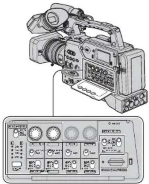
①Set the REC CH SELECT switch.

Select the recording audio input to CH1 with CH1 of the REC CH SELECT switch.
IN1: Records the audio input from the AUDIO INPUT1 (L) jack.
IN3: Records the audio input from the AUDIO INPUT3 jack.
Select the recording audio input to CH2 with CH2 of the REC CH SELECT switch.
IN2: Records the audio input from the AUDIO INPUT2 (R) jack.
Center: Records the audio input from the AUDIO INPUT jack selected with CH1 switch.
IN4: Records the audio input from the AUDIO INPUT4 jack.
Notes
- For stereo recording, set your camcorder to record the left-side sound in CH1 and the right-side sound in CH2.
Tips
- Sony recommends that you set CH2 of the REC CH SELECT switch to the center position in the following cases:
- To avoid no audio input to CH2 by recording the same audio input with that inputted to CH1.
- To record different audio inputs from the same audio source simultaneously with different audio settings to make the audio recording reliable. For example, you can set the audio level manually for the audio input to CH1 and automatically for that to CH2, and record the inputs in the respective channels.
②Set the INPUT1/2/3/4 switch.
If your microphone needs a power supply, set the INPUT1/2/3/4 switch to MIC+48V. If it does not need a power supply, set to MIC.

Notes
- Setting the INPUT1/2/3/4 switch to MIC+48V when a microphone that does not need a power supply is attached may damage the microphone or impair the sound recording quality.
Changing the settings of your camcorder recordings (Continued)

Tips
- Set the INPUT1/2/3/4 switch to MIC+48V when using the supplied microphone.
③Set the level of input to be recorded on each audio track.

If you want to adjust the recording volume automatically, set the CH1 and CH2 switches to AUTO. If you want to adjust it manually, set the switches to MAN. When you set the switches to MAN, 🌘 appears on the screen. The CH switch numbers you set to MAN appear on the right of the icon (My) You can adjust the volume when the switches are set to MAN by turning the CH1 and CH2 dials.
Notes
- Set the INPUT switches for the respective AUDIO INPUT jacks, and the CH switches for the corresponding recording tracks on a tape.
Example of 2CH recording (recording audio input from INPUT1 and INPUT4)
① Set CH1 of the REC CH SELECT switch to IN1 and CH2 to IN4.

②Set the INPUT1 and INPUT4 switches. For example, set the INPUT1 switch to MIC+48V and the INPUT4 switch to MIC when the supplied microphone is
connected to the AUDIO INPUT1 (L) jack, or a microphone that does not need a power supply is connected to the AUDIO INPUT4 jack, as illustrated.

③Set the CH1 and CH2 switches. For example, set the CH1 switch to AUTO and the CH2 switch to MAN to adjust the recording level of CH1 automatically and that of CH2 manually.

Tips
- You cannot adjust the recording levels of CH3 and CH4 during 2-channel recording.
■ 4CH/FS32K recording

In 4-channel recording, the recording channels are designated to their respective input channels, as shown in the following table. You cannot select the channels. The settings of REC CH SELECT switch become ineffective.
| Input Recording channel |
| INPUT1 → CH1 |
| INPUT2 → CH2 |
| INPUT3 → CH3 |
| INPUT4 → CH4 |
Monitor the recording sound
You can select audio output via headphones or line-out.

Select the channels with the AUDIO MONITOR switch A and the MONITOR SELECT button B.
The lamps of the selected output channels light up.
Assigning the functions to the ASSIGN buttons
Some functions need to be assigned to the ASSIGN buttons for use. You can assign a single function to any one of the ASSIGN 1 to 6 buttons on the body or the L1, L2 and RET buttons on the lens.
Notes
- The following functions cannot be assigned to the RET button.
- FOCUS (for changing between automatic focus and manual focus)
- ONE PUSH AF
- FOCUS INFNTY
- FOCUS MACRO
- STEADYSHOT

Tips
- The RET button is an assignable button on non-Carl Zeiss lenses.
Functions you can assign to the ASSIGN buttons
The buttons in parentheses indicate that the functions are assigned to the buttons by default.
• FOCUS (p. 30)
• EXP.FOCUS (p. 31)
• ONE PUSH AF (p. 31)
• FOCUS INFNTY (p. 31)
• FOCUS MACRO (p. 70)
• D.EXTENDER (p. 70) (L1 button)
• HYPER GAIN (p. 67)
• AE SHIFT (p. 68) (ASSIGN 5 button)
• INDEX MARK (p. 49)
• STEADYSHOT (p. 69) (ASSIGN 6 button)
- BACK LIGHT (p. 69)
- SPOTLIGHT (p. 69)
• FADER (p. 70)
• LAST SCN RVW (p. 50)
• REC REVIEW (p. 50) (L2 or RET button)
• END SEARCH (p. 50)
• ZEBRA (p. 76) (ASSIGN 4 button)
• MARKER (p. 77)
• DISPLAY (p. 58)
• TC RESET (p. 85)
• TC COUNTUP (p. 85)
• PHOTO (p. 27)
• REC LAMP[R] (p. 90)
• PICTURE PROFILE (p. 36)
ASSIGN 1-3 buttons

1 Push the MENU/STATUS switch B to MENU.
2 Select the (OTHERS) → [ASSIGN BTN] with the SEL/PUSH EXEC dial A.
3 Select [CAMERA] or [LENS], whichever the ASSIGN button to which you want to assign a function is located, with the SEL/PUSH EXEC dial A.
4 Select the ASSIGN button to which you want to assign a function with the SEL/PUSH EXEC dial A.
- You can select the ASSIGN 1 through 6 buttons on the body and the L1, L2 and RET button on the lens.
- [----] appears if no function is assigned to the ASSIGN button.
5 Select the function that you want to assign with the SEL/PUSH EXEC dial A.
6 Select [OK] with the SEL/PUSH EXEC dial A.
7 Select [RETURN] with the SEL/PUSH EXEC dial A.
8 Push the MENU/STATUS switch B to MENU to hide the menu screen.
Recording an index signal
When you record a scene with an index signal, you can easily find the scene during playback on a device that supports this function.
The index function will make it easier to check the transition of recording or edit your pictures using index signals.
1 Assign [INDEX MARK] to one of the ASSIGN buttons (p. 48).
2 Press the ASSIGN button to which [INDEX MARK] is assigned. During recording
appears for about 7 seconds and an index signal is recorded.
During standby
flashes.
After you press the REC START/STOP button to start recording, appears for about 7 seconds and an index signal is recorded.
To cancel the operation
Press the ASSIGN button to which [INDEX MARK] is assigned again before you start recording.
Notes
- You cannot record an index signal on a recorded tape afterward.
Assigning the functions to the ASSIGN buttons (Continued)
Reviewing the most recently recorded scenes (Rec review)
You can view about 2 seconds of the scene recorded just before you stopped the tape. This is convenient during playback of the latest scene check.
Press the REC REVIEW button or the ASSIGN button to which [REC REVIEW] is assigned during standby.
The last 2 seconds (approx.) of the most recently recorded scenes will be played back, then your camcorder returns to standby.
Searching for the last scene of the most recent recording (End search)
1 Assign [END SEARCH] to one of the ASSIGN buttons (p. 48).
2 Press the ASSIGN button to which [END SEARCH] is assigned.
The last scene of the most recent recording will be played back for about 5 seconds, and the camcorder goes standby at the point where the last recording has finished.
Notes
- End search will not work once you eject the tape.
- End search will not work correctly if a blank section exists between recorded sections on the tape.
Playing back the most recently recorded movies (Last scene review)
You can set your camcorder to automatically rewind the tape to the beginning of the most recently recorded scene, play back to the end of the scene, then stop the tape.
1 Assign [LAST SCN RVW] to an ASSIGN button (p. 48).
2 During standby, press the ASSIGN button to which [LAST SCN RVW] is assigned.
The last scene review starts.
Notes
- If the recording time of the movie is short, [LAST SCN RVW] may not work correctly.
Tips
- If you press the ASSIGN button again during the last scene review, your camcorder plays back the last 5 seconds of the most recently recorded movie, then goes standby at the end of the recording.
Using the Shot transition
You can store settings of focus, zoom, iris, gain, shutter speed and white balance, and smoothly shift from the current settings to the stored settings (shot transition).
For example, you can shift the focus from closer objects to farther objects, or change the depth of field by adjusting the iris. You can also develop scenes under different conditions smoothly. If you store manually adjusted settings of white balance, you can smoothly shift from one scene to another under different conditions, such as from indoor to outdoor.
Sony recommends that you use a tripod to avoid image blurring.
You can set the following items in [SHOT TRANSITION] of the (CAMERA SET) menu (p. 72).
Item Description and settings
| TRANS TIME Setting of transition time(the default setting is[4.0sec])You can set the transitiontime by 0.5 sec between[3.5sec] and [15.0sec], orselect from [20sec],[30sec], [45sec] and[60sec]. |
| START TIMER Setting of timer to start shot transition (the default setting is [OFF]) You can select from [5sec], [10sec] and [20sec]. |
Item Description and settings
| REC LINK Setting of transition |
| linked with start of |
| recording (the default |
| setting is [OFF]) |
| [OFF]: Not to start |
| transition when the |
| recording is started. |
| [SHOT-A]: To start |
| transition to the SHOT-A |
| when the recording is |
| started. |
| [SHOT-B]: To start |
| transition to the SHOT-B |
| when the recording is |
| started. |
| FOCUS TRANS Setting ([ON]/[OFF]) of focus transition (the default setting is [ON]) |
| ZOOM TRANS Setting ([ON]/[OFF]) of zoom transition (the default setting is [ON]) |
| IRIS TRANS Setting ([ON]/[OFF]) of iris transition (the default setting is [ON]) |
Notes
- You cannot manually adjust the focus, zoom, iris, gain, shutter speed and white balance while the CHECK or EXEC lamp is on. You can manually adjust the focus, zoom and iris, even the CHECK or EXEC lamp is on when you set [FOCUS TRANS], [ZOOM TRANS] and [IRIS TRANS] to [OFF], respectively.
- When [EXT REC CTRL] is set to [EXT ONLY], setting [REC LINK] (linked recording) to [SHOT-A] or [SHOT-B] links the start of transition to the start of recording on an external device (HVR-MRC1 or HVR-DR60).

1 Set [S.TRANS/F.MARK] of the (CAMERA SET) menu to [SHOT TRANSITION].
2 Press the SHOT TRANSITION/FOCUS MARKING button D to bring up the shot transition store screen.
The STORE lamp turns on.
3 Press the A button to store the settings in SHOT-A, or the B button to store the settings in SHOT-B.
Notes
- The settings stored in SHOT-A or SHOT-B will be erased when you set the POWER switch to OFF.
4 Press the SHOT TRANSITION/FOCUS MARKING button D again to bring up the shot transition check screen.
The CHECK lamp turns on.
Press the A button to check SHOT-A, or the B button to check SHOT-B. The image will be displayed with the settings stored in the selected SHOT. The focus, zoom, iris, gain, shutter speed and white balance are automatically adjusted to the stored settings.
Notes
- The settings do not shift to the stored settings with the transition time set in [TRANS TIME] (p. 51).
5 Press SHOT TRANSITION/FOCUS MARKING button D again to bring up the shot transition execution screen.
The EXEC lamp turns on.
6 Press the REC START/STOP button A (B or C).
Press the A button for recording with SHOT-A, or the B button for recording with SHOT-B.
The settings shift from the current ones to the stored ones.
Notes
- When you change [SHOT TRANSITION] (p. 51), press the SHOT TRANSITION/FOCUS MARKING button repeatedly to exit the shot transition screen.
- You cannot return from the stored SHOT-A or SHOT-B settings to previous settings after you execute the shot transition during recording.
- If you use the following buttons and switch during the shot transition operation, the shot transition will be canceled:
- PICTURE PROFILE button
- MENU/STATUS switch
-
ASSIGN button to which [EXP.FOCUS] is assigned
-
You can also make a transition from the SHOT-A to the SHOT-B or from the SHOT-B to the SHOT-A. For example, to make a transition from the SHOT-A to the SHOT-B, display the shot transition check screen, press the A button to bring up the SHOT-A and press the REC START/STOP button. Then, display the shot transition execution screen and press the B button.
- You can rehearse the shot transition by pressing the respective buttons (A or B) to which your customized settings are assigned before pressing the REC START/STOP button in step 6.
- You cannot use the shot transition when you use a non-Carl Zeiss lens.
- The settings stored in the memory (SHOT-A/SHOT-B) are cleared when you remove the Carl Zeiss lens, or you adjust the flange focal length.
To cancel the operation
Press the SHOT TRANSITION/FOCUS MARKING button D repeatedly to exit the shot transition screen.
Marking focal point on the screen (Focus marking)
You can mark a focal point, at which you set a subject in focus, on the LCD screen prior to the recording. You can use this function during the manual focus.

1 Set [S.TRANS/F.MARK] of the (CAMERA SET) menu to [FOCUS MARKING].
2 Press the SHOT TRANSITION/FOCUS MARKING button B.
The focus marking bar appears at the bottom of the screen.
3 Adjust the focus by turning the focus ring A and set a focal point.
A cursor on the focus marking bar moves as you turn the focus ring.
4 Press the A button for marking a focal point at position A or the B button for marking a focal point at position B.
When you press the A button, ▼ and A appear on the focus marking bar. When you press the B button, ▲ and B appear on the focus marking bar.

This mark appears when you press the A button.
The color of the marks changes when position A or B matches the current focal point.
Notes
- The focus marking function does not work when [FOCUS MACRO] is set to [ON].
- You cannot use the focus marking when you use a non-Carl Zeiss lens. Marking positions A and B will be cleared when you dismount the lens or turn off the power.
Tips
- You can use the focus marking function during the expanded focus.
Playback

You can play back movies as follows:
1 Set the POWER switch to ON and the CAMERA/VCR switch to VCR

2 Start playing back.
Press ◀◀ (rewind) to go to the point you want to view, then press ▶ (play) to start playback.
- ■ : STOP
- II : PAUSE (Press ▶ or || again to restart the playback)
- ◀◀/▶▶ : REW (Rewind)/FF (Forward)
- /REVIEW/CUE
- ▶ : SLOW
Notes
- Your camcorder automatically goes into a stopped state when it is in pause for more than 3 minutes.
- The screen may temporarily go blank losing images and sound when signals switch between HDV and DVCAM (DV) during playback of a tape in which HDV format and DVCAM (DV) format are mixed.
- You cannot play back movies recorded in HDV format on DVCAM (DV) format video cameras or mini DV players.
- You can play back a DV format tape on your camcorder only when its contents are recorded in the SP mode. You cannot play back movies recorded on the DV format tape in the LP mode.
- Time code and user bits will not be displayed correctly when you play back a tape with no time code or user bit data, or a tape with time code that your camcorder does not support.

Tips
- See page 130 for indicators displayed on the screen during playback.
• See page 58 for how to switch displays during playback.
To search for a scene while viewing a movie
Press / during playback (Picture Search). To view during fast forward, press and hold ▶. To view during rewind, press and hold ◀◀ (Skip Scan).
To adjust the volume
Adjust the volume with the MONITOR dial.
To view still images
①Set the POWER switch to ON and the CAMERA/VCR switch to VCR.
②Press the MEMORY/PLAY button.
③Select a still image that your want to view using the MEMORY -/+ button. To stop viewing still images, press the MEMORY/PLAY button again.
To display the list of still images (index screen)
①Set the POWER switch to ON and the CAMERA/VCR switch to VCR.
②Press the MEMORY/INDEX button.
③Select a still image using the MEMORY -/+ button. To display a single image, move ▶ to that image and press the MEMORY/PLAY button. To stop displaying the list of still images, press the MEMORY/INDEX button again.
To delete still images from the "Memory Stick Duo"
① Do the steps of “To view still images” to display still images that you want to delete.
②Press the MEMORY/DELETE button.
③Select [YES] with the SEL/PUSH EXEC dial.
The still image will be deleted.
Notes
- Still images cannot be restored once you delete them.
- You cannot delete still images when the “Memory Stick Duo” is write-protected (p. 110) or the still image is protected (p. 98).

Tips
- To delete a still image in the index, move ▶ to the still image using the VOLUME/MEMORY button, then do steps ② and ③.
- To delete all still images, do [ALL ERASE] of the (MEMORY SET) menu (p. 87).
Changing/checking the settings in your camcorder

Changing the screen
You can turn on and off the display of the time code, tape counter, and other information on the screen.
Press the DISPLAY button A.
The screen indictors turns on (displayed) and off (not displayed) as you press the button.
When the CAMERA/VCR switch is set to CAMERA, the screen changes (detailed display → simple display → no display) as you press the button.
Tips
- You can display the screen indicators during playback on a TV. Select [V-OUT/PANEL] of [DISP OUTPUT] (p. 80).
- When you assign [DISPLAY] of [ASSIGN BTN] to an ASSIGN button, you can use the ASSIGN button to change the screen.
- To output a signal containing information on indicators such as icons via the COMPONENT OUT jack or the HD/SD SDI OUT jack, set [DISP OUTPUT] to [ALL OUTPUT].
Displaying recording data (Data code)
You can display information, including date, time and camera data, automatically stored during recording on the screen during playback.
1 Set the CAMERA/VCR switch E to VCR.
2 Press the DATA CODE button B during playback or pause.
The screen changes (date and time display → camera data display → no display) as you press the button.

1 SteadyShot off
2 Exposure
AUTO appears during playback of the movie recorded with the iris, gain and shutter speed automatically adjusted.
MANUAL appears during playback of the movie recorded with the iris, gain and shutter speed manually adjusted.
3 Iris
CLOSE appears in the iris value display area during playback of the movie recorded with the iris manually adjusted to its maximum value.
4Gain
5 Shutter speed
6 White balance
PWB appears during playback of the movie recorded with the shot transition or [MANU WB TEMP].
Notes
- The exposure correction value (0EV), shutter speed and iris will be displayed during viewing of still images on “Memory Stick Duo.”
- Date and time will be displayed in the same area when you select the date and time display. If you record without setting date and time, [--- -- ----] and [--:--:--] will be displayed.
- An accurate shutter speed may not be displayed when you playback a tape recorded with your camcorder on another device. Check the data code that is displayed on the screen when you play back the tape on your camcorder for the accurate shutter speed.
- A shutter speed is indicated with [---] during playback of the movie record in the extended clear scan (ECS) mode.
Displaying the settings in your camcorder (Status check)
You can check the settings of the following items.
• Audio setup such as microphone volume level (p. 74)
- Output signal setup ([VCR HDV/DV], etc.) (p. 80)
- Functions assigned to the ASSIGN buttons (p. 48)
- Camera setup (p. 67)
- External devices
1 Push the MENU/STATUS switch C to STATUS.
2 Turn the SEL/PUSH EXEC dial D until a desired display shows up on the screen.
When the CAMERA/VCR switch is set to CAMERA, the display changes in the following sequence:
AUDIO → OUTPUT → ASSIGN → CAMERA → EXT DEVICE (when an external device is connected)
When the CAMERA/VCR switch is set to VCR, the display changes in the following sequence:
AUDIO → OUTPUT → ASSIGN → EXT DEVICE (when an external device is connected)
To hide the display
- Push the MENU/STATUS switch to STATUS.
Connecting a monitor or a TV
To connect to a monitor or recorder without an i, HDV/DV jack, use audio and video cables as below. You do not need an audio cable to connect a monitor that supports SDI audio input via an SDI cable. If the monitor does not support SDI audio input, you need an audio cable even if you connect the monitor via an SDI cable. When using the VIDEO OUT jack, set the VIDEO OUT switch to COMPOSITE (no image on the LCD screen).
Monitor/Recorder
![graph TD A["To audio input jack"] --> B["To SDI jack"] B --> C["To S video jack"] C --> D["To i.LINK input jack"] D --> E["To video input jack"] E --> F["To component input jack"] G["Component video cable (optional)"] --> H["Video cable (optional)"] H --> I["i.LINK cable (optional)"] I --> J["S vide…](/content/2026/07/1523711/images/397c96824d8151adbe54a02e9d567062f8982855194ff82f33e13279b47524be.jpg)
Notes
- Set (IN/OUT REC) menu → [VIDEO OUT] → [SDI/CMPNT] (p. 82) for an external device to which HDV format signals are inputted from your camcorder via an SDI cable or a component video cable. When connecting via an SDI cable, also set [SDI OUTPUT] in the (IN/OUT REC) menu to [ON] (default setting).
- See “Specifications” (p. 117) for details on the HD/SD SDI OUT jack and the COMPONENT OUT jack.
-
Video signals outputted from the HD/SD SDI OUT jack or the COMPONENT OUT jack of your camcorder have the following limitations:
-
Video signals inputted from the HDV/DV jack of your camcorder need to be recorded to output to an external device. When recording video signals and outputting them from the HDV/DV jack to the external device, you can view the movie reproduced by the video signal.
- When recording a video signal inputted from the HDV/DV jack in HDV format and outputting the signal in SDI format, the SDI signal does not meet SDI specifications.
- Image and audio distortion may occur depending on the quality of the i.LINK signal in the device connected to your camcorder via the HDV/DV jack, or the quality or type of SDI input jack of the connected device. Make sure the connected device is appropriate for receiving an SDI video signal.
-
Video signals are simultaneously outputted from the COMPONENT OUT jack and the HD/SD SDI OUT jack. The [SDI/CMPNT] settings in [VIDEO OUT] of the (IN/OUT REC) menu affect both the COMPONENT OUT jack and the HD/SD SDI OUT jack.
-
When down converting an HDV format signal to a DVCAM (DV)signal and outputting it, you can output a 4-channel audio signal via any jack except the HDV/DV jack.
- You cannot up convert a DVCAM (DV) format video signal to an HDV format video signal.
- 1080/24p and 1080/30p video signals are outputted via the COMPONENT OUT jack and the HD/SD SDI OUT jack as 1080/60i video signals.
- Make sure that [VCR HDV/DV] in the (IN/OUT REC) menu is set to [AUTO] (default setting) before connecting an i.LINK cable. If you connect the i.LINK cable before setting [VCR HDV/DV] to [AUTO], your monitor may not recognize video signals.
- You may need to set your monitor to recognize your camcorder when connecting them via an i.LINK cable. Refer to the operating instructions of your monitor.
- A video signal and an audio signal are outputted together when your camcorder is connected to an external device via an i.LINK cable. You cannot output those signals separately.
- When you down convert an HDV format signal with 4-channel recording to a DVCAM (DV) format signal and output it via the iHDV/DV jack, the audio is output through two channels. Set ⇌ (IN/OUT REC) menu → [i.LINK SET] → [DOWN CONV AU] to select [CH1,CH2] or [CH3,CH4] output channels.
- If you change the [SDI/CMPNT] settings in [VIDEO OUT] of the (IN/OUT REC) menu during playback, the image signals outputted from the S VIDEO OUT jack, VIDEO OUT jack and HDV/DV jack may be temporarily distorted.
- When you down convert an HDV format progressive video signal to a DVCAM (DV) format video signal and output it via the i.LINK jack, the output signal is converted into an interlaced video signal.
Using the Menu
Using the menu items
You can change various settings or make detailed adjustments using the menu items displayed on the screen.

1 Set the POWER switch to ON, then set the CAMERA/VCR switch to CAMERA or VCR.
2 Push the MENU/STATUS switch to MENU.
The menu index screen appears.
![CAMERA SET GAIN SETUP SMOOTH GAIN HYPER GAIN AGC LIMIT WB PRESET WB OUTDR LVL WB TEMP SET : [MENU]-END STBY](/content/2026/07/1523711/images/e4a4fafa472ea4df92f230800e30e5022856521fb6d0e4c9f467764a5ae441ac.jpg)
3 Turn the SEL/PUSH EXEC dial until the icon of the desired menu is highlighted, then press the dial to select the menu.

![OTHERS STBY RETURN CAMERA PROF. ASSIGN BTN CLOCK SET WORLD TIME LANGUAGE QUICK REC DATE REC [MENU]: END](/content/2026/07/1523711/images/73470bdf638f9f04b74d93c8483a03931caf715f00f26315a2dda9923259652f.jpg)
4 Turn the SEL/PUSH EXEC dial until the desired menu item is highlighted, then press the dial to select the item.
![OTHERS ASSIGN BTN CLOCK SET WORLD TIME LANGUAGE QUICK REC DATE REC BEEP OFF REC LAMP[R] [MENU] : END](/content/2026/07/1523711/images/1adcbf40baba421b7fe1c60fe587954e7a73ce137d1bea6ec1490b930540e86f.jpg)
The available menu items vary depending on the position of the CAMERA/VCR switch of your camcorder. Unavailable items will be grayed out.
5 Turn the SEL/PUSH EXEC dial until the desired setting is highlighted or to bring up the desired setting, then press the dial to confirm the setting.
![STBY 00:00:28:10 BEEP OFF ON [MENU]: END](/content/2026/07/1523711/images/c7b78e51cf105c01c4f3667c85d599c789fd337a574dbf28c0439310ef1dc27c.jpg)
6 Push the MENU/STATUS switch to MENU to hide the menu screen.
To return to the previous screen, select [RETURN].

(CAMERA SET) menu (p. 67)
| GAIN SETUP ● - | |
| SMOOTH GAIN ● - | |
| HYPER GAIN [IMAGE] | |
| AGC LIMIT ● - | |
| WB PRESET ● - | |
| WB OUTDR LVL ● - | |
| WB TEMP SET ● - | |
| ATW SENS ● - | |
| SMOOTH WB ● - | |
| AE SHIFT [IMAGE] | |
| AE WINDOW ● - | |
| AE RESPONSE ● - | |
| AT IRIS LMT | ● - |
| FLCKR REDUCE | ● - |
| CNTRST ENHCR | ● - |
| BACK LIGHT [AS] | ● - |
| SPOTLIGHT [AS] | |
| STEADYSHOT [AS] | ● - |
| AF ASSIST | ● - |
| FOCUS MACRO [AS] | ● - |
| HANDLE ZOOM | ● - |
| D.EXTENDER [AS] | ● - |
| FADER [AS] | ● - |
| SMTH SLW REC | ● - |
| INTERVAL REC | ● - |
| DV FRAME REC [CMAM][IMAGE] | ● - |
| SHOT TRANSITION | ● - |
| S.TRANS/F.MARK | ● - |
| x.v.Color [CMAR] | ● - |
| COLOR BAR | ● - |
| FLANGE BACK | ● - |

(AUDIO SET) menu (p. 74)
| HDV 2CH/4CH HDY080 | ● - |
| DV AU.MODE DVCAM OV E | ● - |
| AU.LMT CH1,2 | ● - |
| AU.LMT CH3,4 | ● - |
| XLR SET | ● - |

(DISPLAY SET) menu (p. 76)
| ZEBRA | ||
| HISTOGRAM ● - | ||
| PEAKING ● - | ||
| MARKER | ||
| CAM LEVELING ● - | ||
| EXP.FOCUS TYPE ● - | ||
| CAM DATA DSP ● - | ||
| AU.LVL DISP ● - | ||
| ZOOM DISPLAY ● - | ||
| FOCUS DISP ● - | ||
| SHUTTER DISP ● - | ||
| LCD COLOR ● | ● | |
| LCD BL LEVEL ● | ● | |
| VF B.LIGHT | ● ● | |
| VF COLOR | ● ● | |
| LETTER SIZE | ● ● | |
| REMAINING ● | ● | |
| DISP OUTPUT | ● ● | |

(IN/OUT REC) menu (p. 80)
| REC FORMAT | ● - | |
| VCR HDV/DV - ● | ||
| HDV PROGRE. | ● - | |
| DV PROGRE. | ● - | |
| DV REC MODE | ● | |
| DV WIDE REC | ● - | |
| SDI OUTPUT ● | ● | |
| VIDEO OUT | ● | ● |
| i.LINK SET | ● | ● |
| EXT REC CTRL | ● - |

(TC/UB SET) menu (p. 85)
| TC PRESET | ● | ● | |
| TC COUNTUP (AS) | ● | ● | |
| UB PRESET | ● | ● | |
| TC FORMAT ● | ● | ||
| TC RUN | ● | ● | |
| TC MAKE ● | ● | ||
| TC LINK | ●- | ||
| UB TIME REC | ● | ● | |
| UB-DATE/TC-TIME | ● | ● |
Position of CAMERA/VCR switch:
CAMERA
VCR

(MEMORY SET) menu (p. 87)
| ALL ERASE - ● | |||
| FORMAT ● | ● | ||
| FILE NO. ● | ● | ||
| NEW FOLDER ● | ● | ||
| REC FOLDER ● | ● | ||
| PB FOLDER - ● | |||
| (OTHERS) (p. 88) | |||
| CAMERA PROF. ● | ● | ||
| ASSIGN BTN ● | ● | ||
| CLOCK SET ● | ● | ||
| WORLD TIME ● | ● | ||
| LANGUAGE ● | ● | ||
| PB ZOOM - ● | |||
| QUICK REC ● | |||
| DATE REC ● - | |||
| BEEP | ● | ● | |
| REC LAMP[R] ● | |||
| BATTERY TYPE | ● | ● | |
| HOURS METER | ● | ● | |
menu
Settings to adjust your camcorder to the recording conditions (GAIN SETUP/BACK LIGHT/STEADYSHOT, etc.)
The default settings are marked with ▶. The indicators in parentheses appear when the items are selected.
See page 62 for details on selecting menu items.
Push the MENU/STATUS switch to MENU → select the (CAMERA SET) with the SEL/PUSH EXEC dial.
GAIN SETUP
You can set gain values for H, M and L positions of the GAIN switch. The default settings of [H], [M] and [L] are 18dB, 9dB and 0dB, respectively.
①Select [H], [M] or [L] with the SEL/PUSH EXEC dial.
②Set the gain value with the SEL/PUSH EXEC dial, and press the dial.
You can select the value between -6dB and 21dB by 3dB. The larger the value, the higher the gain.
③Select [OK] with the SEL/PUSH EXEC dial.
④Push the MENU/STATUS switch to MENU to hide the menu screen.
SMOOTH GAIN
You can set the transition speed at which the gain setting shifts from one value to another, set for the gain switch positions, when you switch the gain switch from a position to another. You can select the transition speed from [FAST], [MIDDLE] and [SLOW] or set to [OFF]. The default setting is [OFF].
HYPER GAIN
AS
When you set this function to [ON] (by the) can increase the gain to its limit. The default setting is [OFF].
Notes
- During the hyper gain, you cannot use the following function.
- [BACK LIGHT]
- [SPOTLIGHT]
- During the hyper gain, the picture quality will be reduced due to noise.
- [HYPER GAIN] is automatically set to [OFF] if you turn the power off and back on.

Tips
- You are recommended to use this function with manual focus.
AGC LIMIT
You can select the upper limit for the Auto Gain Control (AGC) from [OFF] (21dB, the default setting), [18dB], [15dB], [12dB], [9dB], [6db], [3dB] and [0dB].
Notes
- If you adjust the gain manually, you cannot obtain the effect of [AGC LIMIT].
WB PRESET
You can use the preset white balance. For more details, see page 34.
WB OUTDR LVL
You can set an offset value to adjust the outdoor white balance when you set [WB PRESET] to [OUTDOOR]. You can select the offset value from [-7] (bluish) - [0] (normal) - [+7] (reddish). The default setting is [0].
Push the MENU/STATUS switch to MENU → select the 📄 (CAMERA SET) with the SEL/PUSH EXEC dial.
WB TEMP SET
You can set the color temperature between 2,300K and 15,000K in 100K steps when you set [WB PRESET] to [MANU WB TEMP].
ATW SENS
You can set the auto white balance operation under a reddish light source such as an incandescent lamp or candle, or under a blueish light source such as in outdoor shade.
▶ INTELLIGENT
Automatically adjusts the white balance so that scenes look natural for the light source.
HIGH
Automatically adjusts the white balance while reducing redness or blueness.
MIDDLE
LOW
Automatically adjusts the white balance while increasing redness or blueness.
Notes
- This is only effective when white balance is adjusted automatically.
- [ATW SENS] is not effective under a clear sky or the sun.
SMOOTH WB
You can set the transition speed at which the color temperature values shifts from the one set for one of the WHT BAL switch positions to the other set for the other WHT BAL switch position when you switch the positions. You can select the transition speed from [FAST], [MIDDLE] and [SLOW] or set to [OFF]. The default setting is [OFF].
AE SHIFT AS
You can set an offset value to adjust the automatic exposure adjustment value between [-7] (dark) and [+7] (bright) with the SEL/PUSH EXEC dial. The default setting is [0]. And selected value appears on the screen when you change the value from the default setting.
Notes
- This function is not effective while you adjust the iris, shutter speed and gain all manually.
- This function is not effective when [HYPER GAIN] is set to [ON].
AE WINDOW
You can select a photometric area in which the automatic exposure adjustment function detects changes in the brightness of the subject to automatically adjust the exposure. This function is not effective during the manual exposure adjustment.

STANDARD TYPE 1


TYPE 3TYPE 2


TYPE 5TYPE 4
Tips
- The photometric area stays the same even when you change the aspect ratio.
Example: TYPE 4

AE RESPONSE
You can select the speed at which the automatic exposure adjustment function follows changes in the brightness of the subject. You can select the speed from [FAST], [MIDDLE] and [SLOW]. The default setting is [FAST].
AT IRIS LMT
You can select the highest iris value for the automatic adjustment from [F11], [F9.6], [F8], [F6.8], [F5.6], [F4.8] and [F4]. The default setting is [F11].
Notes
- This function is not effective during the manual iris adjustment.
FLCKR REDUCE
▶ ON
Reduces flickering. Flickering of the screen under a light source such as fluorescent lamps will be reduced.
OFF
Not reduce flickering. Select this when you do not want to reduce flickering.
Notes
- Flickering may not be reduced for certain light sources.
CNTRST ENHCR
When you set this function to [ON], your camcorder detects high contrast images, such as backlit scenes, and automatically improves the unexposed images. The default setting is [OFF].
Notes
- When you set [BACK LIGHT] to [ON], [CNTRST ENHCR] is temporarily disabled.
BACK LIGHT AS
When you set this function to [ON] (☑), you can correct backlighting. The default setting is [OFF].
Notes
- The back light function is canceled when you set [SPOTLIGHT] to [ON].
SPOTLIGHT AS
When you set this function to [ON] ( ) you can prevent overexposure of light during recording of a subject under strong light, such as a stage. For example, you can prevent people's faces from over-highlighting. The default setting is [OFF].
Notes
- The spotlight function is canceled when you set [BACK LIGHT] to [ON].
- You cannot use the spotlight function if at least two of iris, gain, and shutter speed are adjusted manually.
STEADYSHOT AS
ON/OFF
When you select [ON], you can reduce camera shakes. Select [OFF] ( when you use a tripod (optional) to make images look natural. The default setting is [ON].
TYPE
You can select a type of camera-shake reduction for different recording situations.
Push the MENU/STATUS switch to MENU → select the 📄 (CAMERA SET) with the SEL/PUSH EXEC dial.
HARD
Reduces camera shakes at a high level.
This setting is not suitable for panorama tilt recordings.
▶ STANDARD
Reduces camera shakes at a standard level.
SOFT
Reduces camera shakes at a low level. Slight unsteadiness remains in movies, which make the movies look as they are.
AF ASSIST
When you set this function to [ON], you can temporarily focus manually using the focus ring during the auto focus adjustment. The default setting is [OFF].
Notes
- This function is effective only when the focus ring is set to the mode B position (p. 30).
FOCUS MACRO AS
When you set this function to [ON], you can focus on a subject within 80 cm (about 2 5/8 feet). The default setting is [ON].
When you set this function to [OFF] (OFF) you can set fine focus on a subject further than 80 cm regardless of the zoom position although you will lose focus on a subject within 80 cm.
Notes
- This function is effective only when the focus ring is set to the mode B position (p. 30).
HANDLE ZOOM
You can select the zoom speed for the FIX position of the handle zoom switch from [1] (slow) through [8] (fast). The default setting is [3].
D.EXTENDER AS
When you set this function to [ON] ( ) the displayed image becomes 1.5 times larger. The image quality decreases because the image is digitally processed. This function helps you to focus on far-away subjects such as a wild bird away at a distance. The default setting is [OFF].
Notes
- This function is automatically set to [OFF] when you turn the power off and back on.
FADER AS
You can add visual effects to transition between scenes.
①Select [WHITE FADER] or [BLACK FADER] during standby to fade in with the selected effect or recording to fade out with the selected effect.
②Press the REC START/STOP button.
The fader indicator stops flashing and disappears when the fading is complete.
To cancel before starting the operation, select [OFF] in step ①.
The setting will be cleared every time you press the REC START/STOP button.
STBY REC
Fading out Fading in
WHITE FADER


BLACK FADER



Notes
- This function is automatically set to [OFF] when you turn the power off and back on.
SMTH SLW REC
Fast moving subjects and actions, which cannot be captured under the general recording conditions, can be recorded in smooth moving slow-motion.
This is useful for recording fast actions such as a golf or tennis swing.
①Set [REC TIME].
Select the recording time from [3sec] (the default setting), [6sec] and [12sec].
The picture quality deteriorates as the recording time increases.
②Set [REC TIMING].
Select the recording timing from [START TRIGGR] and [END TRIGGER] to record the action after or before the REC START/STOP button is pressed.
![[START TRIGGR]* [END TRIGGER]](/content/2026/07/1523711/images/fb7f1ea2328a442f5f433614898a5f7f9fff9c952ce774cfaafbd03868e773fb.jpg)
* The default setting is [START TRIGGR].
③Start recording.
Select [EXECUTE], then press the REC START/STOP button on the [SMTH SLW REC] screen.
A slow-motion movie about 4 times longer than your [REC TIME] setting is recorded. Recording ends when [Recording...] disappears from the screen.
To cancel [SMTH SLW REC], push the MENU/STATUS switch to MENU.
Notes
- Sounds cannot be recorded.
- The settings are automatically cleared when you turn the power off and back on.
-
The shutter speed is automatically set to 1/250 second when you start [SMTH SLW REC].
-
The shutter speed is fixed to 1/250 second when you set the SHUTTER switch to OFF.
- You cannot select extended clear scan (ECS) mode or SLS mode during [SMTH SLW REC]. Pushing the SHUTTER switch to SEL only enables you to select manual mode or auto mode.
- The recording time may be shorter than the set time, depending on recording conditions.
- The image quality is lower than with the regular recording.
INTERVAL REC
You can record a series of movies on a tape at regular intervals. This function is useful to observe things like cloud movements or daylight changes. The scenes run smoothly into each other when you play back the tape. Use the AC Adapter to obtain AC power for long recording.

① Select [ON/OFF] → [ON] with the SEL/PUSH EXEC dial.
②Perform the following step if you are changing the recording time from the default setting of [0.5sec]. If you are keeping the default recording time, go straight to step ③.
Select [REC TIME] → [0.5sec], [1sec], [1.5sec] or [2sec] with the SEL/PUSH EXEC dial.
③Perform the following step if you are changing the interval time from the default setting of [30sec]. If you are keeping the default interval time, go straight to step ④. Select [INTERVAL] → [30sec], [1min], [5min] or [10min].
④Select [OK] with the SEL/PUSH EXEC dial.
⑤Push the MENU/STATUS switch to MENU to hide the menu screen.
⑥Press the REC START/STOP button.
The [INTERVAL REC] recording starts.
To cancel [INTERVAL REC], press the REC START/STOP button.
Push the MENU/STATUS switch to MENU → select the 📄 (CAMERA SET) with the SEL/PUSH EXEC dial.
The operation of your camcorder differs depending on when you press the REC START/STOP button. If you press the button during [INTERVAL REC] recording, the recording temporarily stops. If you press it again, the [INTERVAL REC] recording restarts. If you press the button during [INTERVAL REC] interval, the [INTERVAL REC] recording stops and regular recording starts. If you press it again, regular recording stops. If you press the button once again, the [INTERVAL REC] recording restarts. To cancel the [INTERVAL REC] recording, select [ON/OFF] → [OFF] with the SEL/PUSH EXEC dial.
Notes
- The recording time and interval time may differ slightly from the settings.
- If you focus manually, you can get sharp images even if the lighting changes.
DV FRAME REC
DVCAM
DV SP
You can record stop motion (or frame-by-frame) animation movies. That type of animation uses a technique of changing the subject, such as a doll or a toy's positions and recording it at each different position while your camcorder sits still.
▶ OFF
Not use this function.
ON ( )
Records a movie by stop motion (or frame-by-frame) technique.
①Select [ON] with the SEL/PUSH EXEC dial.
②Push the MENU/STATUS switch to MENU to hide the menu screen.
③Press the REC START/STOP button.
Your camcorder records a movie for about 6 to 9 frames and returns to standby.
④Move the subject and repeat step ③.
Notes
- When you use frame recording continuously, the remaining tape time will not be indicated correctly.
- The last scene will be longer than other scenes.
- You cannot record index signals during frame recording.
- This function is automatically set to [OFF] when you turn the power off and back on.
SHOT TRANSITION
See page 51.
S.TRANS/F.MARK
You can select a function to be assigned to the SHOT TRANSITION/FOCUS MARKING button.
▶ SHOT TRANSITION
Select to assign the shot transition function to the button.
FOCUS MARKING
Select to assign the focus marking function to the button.
x.v.Color HDV1080i
When you set this function to [ON], you can record with the wider color range. Your camcorder can reproduce brilliant and vivid colors for flowers and the beautiful blue-green of tropical oceans that cannot be matched by conventional technologies.
Notes
- The colors may not be well reproduced when you play back a movie recorded with this function set to [ON] on a TV that does not support x.v.Color.
- You cannot set [x.v.Color] in the following cases:
- When recording in SD (standard) format
- When recording movies
- When you set [x.v.Color] to [ON], the picture profile will be disabled.
COLOR BAR AS
TYPE
Selects a type of the color bars.

TYPE 1

TYPE 2

TYPE 3

TYPE 4 (75% brightness of TYPE 3)
TONE
Outputs audio tone signals (1 kHz: full bit -20 dB) when you set the OUTPUT/DCC switch to BARS and [TONE] to [ON]. The default setting is [OFF].
FLANGE BACK
You can select a mode for the flange focal length adjustment. The flange focal length
is a distance from the lens flange to the plane of the image along the optical axis. See page 9 for details.
▶ AUTO ADJUST
Automatically adjusts the flange focal length.
MANU ADJUST
Manually adjusts the flange focal length.

(AUDIO SET) menu
Settings for the audio recording (HDV 2CH/4CH/XLR SET, etc.)
The default settings are marked with ▶. The indicators in parentheses appear when the items are selected.
See page 62 for details on selecting menu items.
Push the MENU/STATUS switch to MENU → select the (AUDIO SET) with the SEL/PUSH EXEC dial.
HDV 2CH/4CH
HDV1080i
You can select the number of recording channels for HDV format recording.
▶ 2CH
Records in two channels, CH1 and CH2. Signals from AUDIO INPUT1 (L)-4 are recorded in CH1 and CH2 (p. 45).
4CH
Records in four channels. Signals from AUDIO INPUT1 (L), AUDIO INPUT2 (R), AUDIO INPUT3 and AUDIO INPUT4 are recorded in CH1, CH2, CH3 and CH4, respectively.
Notes
- The REC CH SELECT switch settings become ineffective when you select [4CH].
DV AU.MODE
Records in the 12-bit mode (2 stereo sounds). Select this setting for the DVCAM/DV SP recording.
▶ FS48K (48k
Records in the 16-bit mode (1 stereo sound with high quality). Select this setting for the DVCAM/DV SP recording.
Notes
- When recording in the HDV format, sound is automatically recorded in the [FS48K] mode.
AU.LMT CH1,2
You can set the clipping-noise reduction function for CH1 and CH2.
▶ OFF
Disables the function.
ON
Enables the function.
Notes
- This function is available only when you set the CH1/CH2 switch to MAN.
AU.LMT CH3,4
You can set the clipping-noise reduction function for CH3 and CH4
▶ OFF
Disables the function.
ON
Enables the function.
Notes
- This function is available only when you set the CH3/CH4 switch to MAN.
XLR SET
AGC CH1,2
You can select either linked or separate AGC (Auto Gain Control) of CH1 and CH2 when using an external microphone.
▶ SEPARATE
Separately applies the AGC for CH1/CH2. Sound inputs from CH1 and CH2 will be recorded as separate sound.
LINKED
Applies the AGC of CH1 linked with that of CH2. Sound inputs from CH1 and CH2 will be recorded as a set of sound such as stereo sound. Appears on the status check screen.
Notes
- This setting becomes effective when the CH1 and CH2 switches are both set to AUTO and the INPUT switches to CH1 and CH2 are set to MIC or MIC+48V, or both are set to LINE (p. 45).
AGC CH3,4
You can select either linked or separate AGC (Auto Gain Control) of CH3 and CH4 when using an external microphone.
▶ SEPARATE
Separately applies the AGC for CH3/CH4. Sound inputs from CH3 and CH4 will be recorded as separate sound.
LINKED
Applies the AGC of CH3 linked with that of CH4. Sound inputs from CH3 and CH4 will be recorded as a set of sound such as stereo sound. Appears on the status check screen.
Notes
- This setting becomes effective when the CH3 and CH4 switches are both set to AUTO and the INPUT3 and INPUT4 switches are set to MIC or MIC+48V, or both are set to LINE (p. 45).
■ INPUT1 MIC NR
Reduces noise from the microphone.
▶ ON
Reduces noise from the microphone.
NR appears on the status check screen.
OFF
Does not reduce noise from the microphone.
Notes
- The setting is not effective when you set the INPUT1 switch to LINE.
INPUT1 TRIM
Adjusts the input signal level from INPUT1.
You can select from [-18dB], [-12dB], [-6dB], [0dB], [6dB] and [12dB]. The default setting is [0dB].
Notes
- The setting is not effective when you set the INPUT1 switch to LINE.
■ INPUT1 WIND
▶ OFF
Disables wind noise reduction.
ON
Enables wind noise reduction.

appears on the status check screen.
Notes
- The setting is not effective when you set the INPUT1 switch to LINE.
■ INPUT2 MIC NR
INPUT2 TRIM
INPUT2 WIND
■ INPUT3 MIC NR
■ INPUT3 TRIM
■ INPUT3 WIND
■ INPUT4 MIC NR
INPUT4 TRIM
INPUT4 WIND
You can set INPUT2, INPUT3 and INPUT4 in the same way as INPUT1.
Tips
- 48 dBu is set as 0dB in your camcorder.
- Set [INPUT TRIM] to [0dB] for the supplied microphone (ECM-XM1).
- Set [INPUT TRIM] to [12dB] for the optional microphone (Sony ECM-NV1).
- The INPUT TRIM function adjusts the input level from an external microphone. When using a highly sensitive microphone or recording loud sound, set this to the minus side. When using a less sensitive microphone or recording quiet sound, set it to the plus side.
- When recording loud sound, the sound may be distorted at either the input point or the recording point. If it is distorted at the input point, adjust the sound using the INPUT TRIM
Push the MENU/STATUS switch to MENU → select the (AUDIO SET) with the SEL/PUSH EXEC dial.
function. If it is distorted at the recording point, lower the total volume level manually.
- If you set INPUT TRIM too far to the minus side, the microphone volume becomes too low, resulting in a poor signal to noise ratio.
- Test the effect of the INPUT TRIM function according to the microphone used or the sound field of the recording site before actual recording.
(DISPLAY SET)
menu
Display settings of the display and the viewfinder (MARKER/VF B.LIGHT/DISP OUTPUT, etc.)
The default settings are marked with ▶. The indicators in parentheses appear when the items are selected.
See page 62 for details on selecting menu items.
Push the MENU/STATUS switch to MENU → select the (DISPLAY SET) with the SEL/PUSH EXEC dial.
ZEBRA AS
You can display a zebra pattern as a guide for adjusting brightness.
ON/OFF
When you select [ON], and the brightness level appear on the screen. The zebra pattern will not be recorded on a tape or a “Memory Stick Duo.”
LEVEL
You can select the brightness level between 70 and 100 or 100+.
Tips
- The zebra pattern is a strip pattern displayed over a part of an image on the screen when the part is higher than a preset brightness level.
HISTOGRAM
You can adjust the iris while referring to a histogram. A histogram is a graph that shows the distribution of the image brightness. You can use the histogram as a guide for adjusting the iris. The histogram will not be recorded on a tape or a "Memory Stick Duo."
▶ OFF
Does not display a histogram.
NORMAL
Displays a histogram.
ADVANCE
Displays a histogram, and a bar that indicates an average of the brightness levels around the center of an image (within the marker) on the histogram.


Tips
- The left area on the graph shows the darker areas of the image while the right area shows the brighter areas.
- A vertical line that indicates the brightness level of [ZEBRA] will be displayed on the histogram when you set [ZEBRA] to [ON].
PEAKING
You can select a peaking sensitivity from [HIGH], [MIDDLE] and [LOW]. The default setting is [MIDDLE].
Notes
- You cannot record an image with enhanced details on a tape or a “Memory Stick Duo.”

Tips
- You can focus more easily using this function in combination with the expanded focus function (p. 31).
MARKER
AS
ON/OFF
When you select [ON], you can display markers. The default setting is [OFF]. Markers will not be recorded on a tape or "Memory Stick Duo."
CENTER
When you select [ON], you can display a marker at the center of the screen. The default setting is [ON].

ASPECT
When you select [ON], you can display markers at boundaries of display area defined by the aspect ratio, which you can select from [4:3], [13:9] and [14:9]. The default setting is [OFF].

SAFETY ZONE
When you select [ON], then [80%] or [90%] , you can display markers at boundaries of display area that regular home TVs can display. The default setting is [OFF].
GUIDEFRAME
When you select [ON], you can display frame markers that help you to check horizontal and vertical positions of a subject. The default setting is [OFF].

Notes
- You cannot display markers on an external device connected to your camcorder via an analog jack.
- You cannot display markers when you set [DATE REC] to [ON].
Push the MENU/STATUS switch to MENU → select the □(DISPLAY SET) with the SEL/PUSH EXEC dial.

Tips
- You can display all types of markers at the same time.
- You can obtain a balanced composition by positioning the subject at the cross points of the guideframe marker.
- You can display markers only on the LCD panel and viewfinder. You cannot display them on an external device.
CAM LEVELING
When you set this function to [ON], you can display a level meter to check the level of your camcorder. The default setting is [OFF].
EXP.FOCUS TYPE
You can set a type of the expanded focus display.
▶ TYPE 1
Simply enlarges images.
TYPE 2
Enlarges and shows images in white and black.
CAM DATA DSP (Camera data display)
When you set this function to [ON], you can constantly display the iris, shutter speed and gain settings on the screen. The default setting is [OFF].

Gain value
Tips
- The settings appear on the screen during the manual adjustment regardless of the settings of this function.
- indicates that the settings are automatically adjusted values.
- The displayed settings are different from the settings that will be displayed when you press the DATA CODE button (p. 58).
AU.LVL DISP (Audio level display)
When you set this function to [ON], you can display the audio level meter on the screen. The default setting is [ON].

Tips
- You can switch what channels to be displayed, CH1/CH2 or CH3/CH4, with the AUDIO LEVEL DISPLAY switch.
ZOOM DISPLAY
▶ BAR
Displays a bar that indicates the zoom position.
NUMBER
Displays a number (0 through 99) that indicates the zoom position.
FOCUS DISP
You can select how to display the focal distance during manual focus.
▶ METER
Displays the focal distance in meters.
FEET
Displays the focal distance in feet.
SHUTTER DISP
You can select how to display the shutter speed.
▶ SECOND
Displays the shutter speed in seconds.
DEGREE
Displays the shutter speed in degrees.
The shutter speed equal to the period that your camcorder reads image data from the image sensor is defined as 360 degrees.
The degree is calculated based on this definition and displayed.
- When [SCAN TYPE] is set to [60], 1/60 second is defined as 360 degrees.
- When [SCAN TYPE] is set to [24] or [24A], 1/24 second is defined as 360 degrees.
- When [SCAN TYPE] is set to [30], 1/30 second is defined as 360 degrees.
For details on [SCAN TYPE], see [HDV PROGRE.] (p. 81) or [DV PROGRE.] (p. 82).
Notes
- When you press the DATA CODE button, the shutter speed will be displayed in seconds regardless of the setting of this function.
Tips
- Shutter speed slower than 360° are displayed in multiples of 360° , such as 360° × 2 .
LCD COLOR
You can adjust the color level of the LCD panel. Changes in the LCD color level will not affect the color level of recording images.
LCD BL LEVEL
You can adjust the backlight level of the LCD screen.
▶ NORMAL
Standard brightness.
BRIGHT
Brightens the LCD screen.
VF B. LIGHT
You can adjust the brightness of the viewfinder.
▶ NORMAL
Standard brightness.
BRIGHT
Brightens the viewfinder screen.
VF COLOR
▶ ON
Displays images in the viewfinder in color.
OFF
Displays images in the viewfinder in black and white.
LETTER SIZE
▶ NORMAL
Displays the menu in regular letter size.
2×
Displays the selected menu items in letter size, the height of which is doubled.
Push the MENU/STATUS switch to MENU → select the (DISPLAY SET) with the SEL/PUSH EXEC dial.

REMAINING
▶ AUTO
Displays the remaining time of a tape for about 8 seconds in the following situation:
- When you set the CAMERA/VCR switch to VCR or CAMERA with a cassette inserted.
- When you press ▶ (Play) or the DISPLAY/BATT INFO button.
ON
Always displays the remaining time of a tape. The remaining time is not displayed when you insert a new tape or a tape that is rewound to the beginning. It is displayed when you start playback or recording. It is always displayed on the sub LCD monitor.
DISP OUTPUT
You can select outputs to which display information, such as time code, is outputted.
▶ LCD PANEL
Outputs the information to the LCD screen and viewfinder.
V-OUT/PANEL
Outputs the information to the LCD screen and composite output.
ALL OUTPUT
Outputs the information to the LCD screen, SDI output, component output and composite output.

(IN/OUT REC)
menu
Recording settings, input and output settings (REC FORMAT/HDV PROGRE./VIDEO OUT/EXT REC CTRL, etc.)
The default settings are marked with ▶. The indicators in parentheses appear when the items are selected.
See page 62 for details on selecting menu items.
Push the MENU/STATUS switch to MENU → select the (IN/OUT REC) with the SEL/PUSH EXEC dial.
REC FORMAT
You can select a recording format.
▶ HDV1080i (HDV1080i
Records in the HDV1080i format.
DV (DVCAM DV SP
Records in the DVCAM (DV) format.
Set also [DV REC MODE] when you record in this format.
Notes
- Set also [i.LINK SET] when you output a movie to an external device through an i.LINK cable (p. 83).
VCR HDV/DV
You can select a type of output signal to an external device for playing back a movie on the device. Select [AUTO] in most cases. When you connect your camcorder to an external device with an i.LINK cable, select a type of input and output signals to and from the external device via the HDV/DV jack. You can record or play back a movie reproduced by the selected type of signals.
▶ AUTO
Automatically switches between HDV signals and DV signals during playback. During the i.LINK connection, recognizes HDV signals and DVCAM (DV) signals, and automatically inputs or outputs the
signals to or from the external device via the i.HDV/DV (i.LINK) jack for recording or playback.
HDV (HDV1080i
Plays back only HDV format sections of a tape.
During the i.LINK connection, inputs or outputs only HDV signals to or from an external device via the HDV/DV (i.LINK) jack for recording or playback.
Select this setting when you connect your camcorder to your computer.
DV (DV)
Plays back only DVCAM (DV) format sections of a tape.
During the i.LINK connection, inputs or outputs only DVCAM (DV) signals to or from an external device via the HDV/DV (i.LINK) jack for recording or playback. Select this setting when you connect your camcorder to your computer.
Notes
- Make sure to disconnect the i.LINK cable prior to changing the setting. Otherwise, a video device may not recognize video signals.
- When you select [AUTO], images and sounds may be cut off on switching between HDV signals and DVCAM (DV) signals.
- When you set [i.LINK SET] → [HDV → DV CONV] to [ON], the following signals will be outputted:
– [AUTO]: HDV signals are converted to DVCAM (DV) signals and outputted. DVCAM (DV) signals are outputted without any conversion.
– [HDV]: HDV signals are converted to DVCAM (DV) signals and outputted. DVCAM (DV) signals will not be outputted.
– [DV]: DVCAM (DV) signals are outputted without any conversion. HDV signals will not be outputted.
HDV PROGRE. HDV1080i
REC TYPE
You can select an HDV recording format from [INTERLACE] and [PROGRESSIVE].
SCAN TYPE
You can select a scan type for recording in HDV format.
▶ 60
Records by the interlace scan.
24
Records 24 frames per second.
24A
Records 24 frames per second.
The phase of the 60i conversion is reset each time recording starts.
30
Records 30 frames per second.
Notes
- Selectable [SCAN TYPE] settings differ depending on the setting of [REC TYPE].
- [INTERLACE]: [60], [24], [24A], [30]
- [PROGRESSIVE]: [24], [30]
- You can only play back a tape recorded with the [REC TYPE] set to [PROGRESSIVE] on a device that supports playback of a tape recorded by progressive scanning.
- When recording in HDV format in [24A] mode, the time code does not progress correctly from scene to scene.
When playing back those movies, a momentary pause will occur between scenes. In this case, you can copy the movies without the pause from your camcorder to a computer via an i.LINK cable and use them on the computer as normal movies.
- When [REC TYPE] is set to [PROGRESSIVE] and [SCAN TYPE] to [24], movies and time codes are recorded at 24 frames per second and indicators are displayed at 30 frames per second. When using the HDV/DV jack, the recorded signal is outputted at the following frame rate depending on the setting of (IN/OUT REC) menu → [i.LINK SET] → [HDV → DV CONV]:
[OFF]: 24 frames per second
[ON]: 30 frames per second
When using other jacks, the recorded signal is outputted at 30 frames per second.
Push the MENU/STATUS switch to MENU → select the ⇌ (IN/OUT REC) with the SEL/PUSH EXEC dial.
DV PROGRE. DVCAM DV SE
SCAN TYPE
You can select a scan type for recording in DVCAM/DV format.
▶ 60
Records by the interlace scan.
24
Records 24 frames per second.
30
Records 30 frames per second.
DV REC MODE (DV Recording mode) DVCAM DV 亚
This function is available only when you set [REC FORMAT] to [DV].
▶ DVCAM (DVCAM
Records in the DVCAM format.
DV SP (DV SP
Records in the SP (Standard Play) mode of the DV format to record for a longer time than in the DVCAM format.
Notes
- Mosaic-like disturbance or audio interruption may occur when you play back a movie recorded in the DV SP mode by another device.
- Image may be distorted or time code may not be properly connected between the scenes recorded in the DVCAM mode and DV SP mode.
DV WIDE REC DVCAM DV SE
You can record a movie in an aspect ratio that matches that of a TV that you want to connect. Refer also to the instruction manuals that come with the TV.
▶ ON
Records a movie in an aspect ratio that matches the full screen of a 16:9 (wide) TV.
OFF (4:3)
Records a movie in an aspect ratio that matches the full screen of a 4:3 TV.
Notes
- Set [DV WIDE CONV] correctly to suite a TV that you want to connect for playback (p. 81).
- The aspect ratio will be fixed to 16:9 and you cannot set it to 4:3 when you record in HDV format.
SDI OUTPUT
Outputs signals from the HD/SD SDI OUT jack. The default setting is [ON].
VIDEO OUT
SDI/CMPNT
You can select the type of connection when connecting your camcorder to a TV with the SDI or component input jack.
480i
Supports connection between your camcorder and a TV with a component input jack that supports the 480i format.
▶ 1080i/480i
Supports connection between your camcorder and a TV with a component input jack that supports the 1080i format.
DOWN CONVERT
You can select a down convert type when you down-covert HDV signal to DV signal. Use this function for signals outputting from the following output jacks:
- Component (480i)
-S Video - Audio/Video
▶ SQUEEZE
Outputs a horizontally compressed image while maintaining its original height.
LETTER BOX
Outputs an image with black bars added to the top and bottom of the original image, while maintaining the original aspect ratio.
EDGE CROP
Outputs the central portion of the original image by cropping its right and left edges.
Notes
- When you view a movie recorded in the DVCAM (DV) format with [DV WIDE REC] set to [ON] on a standard 4:3 TV, images of the movie may appear vertically compressed. In such a case, set [DV WIDE CONV] to [LETTER BOX] or [EDGE CROP].
DV WIDE CONV
You can select a down convert type when you down-covert DV widescreen signal to DV signal.
Use this function for signals outputting from the following output jacks:
- Component (480i)
- S Video
- Audio/Video
▶ SQUEEZE
Outputs a horizontally compressed image while maintaining its original height.
LETTER BOX
Outputs an image with black bars added to the top and bottom of the original image, while maintaining the original aspect ratio.
EDGE CROP
Outputs the central portion of the original image by cropping its right and left edges.
SD-SDI SET
VIDEO INDEX
Adds a video index signal that includes information on aspect ratio and signal format to SDI output signals. The default setting is [ON].
RP188 ATC
Adds an Ancillary Time Code (ATC) to the SDI output signal. The default setting is [ON].
VITC LINESEL
Selects the vertical blanking interval line of the SD video signal, in which the vertical interval time code (VITC) is
recorded, between 12 and 20. The default setting is 16.
i.LINK SET
HDV → DV CONV
When you set this function to [ON], you can convert HDV format signals to DV format signals and output the DV format signals to an external device via the i.HDV/DV (i.LINK) jack. You can output DV format signals without any format conversion. The default setting is [OFF].
DOWN CONVERT
You can set a down convert type when you set [HDV → DV CONV] to [ON] to convert HDV format signals to DV format signals.
▶ SQUEEZE
Outputs a horizontally compressed image while maintaining its original height.
EDGE CROP
Outputs the central portion of the original image by cropping its right and left edges.
DOWN CONV AU
▶ CH1,CH2
Outputs audio signals from CH1 and CH2.
CH3, CH4
Outputs audio signals from CH3 and CH4.
Notes
- When you set [HDV → DV CONV] to [ON] during 4-channel audio recording on an HDV device, only audio in the channel selected in [DOWN CONV AU] is outputted from the i. HDV/DV (i.LINK) jack.
- For i.LINK connection, see [VCR HDV/DV] (p. 80).
- Disconnect the i.LINK cable before setting [i.LINK SET]. Otherwise, the connected video device may not be able to recognize the video signal from your camcorder.
- Even when you select [CH3,CH4] during HDV2CH recording, only audio in CH1 and CH2 will be outputted from the HDV/DV (i.LINK) jack.
EXT REC CTRL
You can connect your camcorder to an HDV/DVCAM/DV compatible device (digital HD video camera recorder, digital video camera recorder, hard disc recorder, etc.) with an i.LINK cable, and record movies on your camcorder and the connected device simultaneously, or continue recording from your camcorder to the connected device.
Refer also to the instruction manuals supplied with the connecting devices.
REC CTL MODE
▶ OFF
Does not record on a connected device.
SYNCHRONOUS (EXT)
Records movies, sound and time code on a connected device in synchronization with your camcorder.
RELAY (EXT)
Records movies, sound and time code on a connected device when a tape on your camcorder reaches close to the end during recording.
EXT ONLY (EXT)
You can operate an external recording unit* with the REC START/STOP button of your camcorder.
*HVR-MRC1(supplied) or HVR-DR60 (optional)
Notes
- When this function is set to [EXT ONLY], does not flash even when there is no tape inserted.
- You can use the REC START/STOP button of your camcorder as a recording start/stop button for the external recording unit when you set this function to [EXT ONLY]. Use the REC button of the video control buttons (p. 125) to start recording on a tape or the STOP button to stop recording.
- EXTONLY) flashes when you connect an external recording unit that is not supported by [EXT ONLY].

STBY COMMAND
▶ REC PAUSE
Stops recording operation of a connected device by putting it in pause when you stop recording operation of your camcorder.
STOP
Stops recording operation of a connected device when you stop recording operation of your camcorder.
(TC PRESET/UB PRESET/TC LINK, etc.)
The default settings are marked with ▶. The indicators in parentheses appear when the items are selected.
See page 62 for details on selecting menu items.
Push the MENU/STATUS switch to MENU → select the b(TC/UB SET) with the SEL/PUSH EXEC dial.
TC PRESET
PRESET
You can preset the time code.
①Select [TC PRESET] with the SEL/PUSH EXEC dial.
②Select [PRESET] with the SEL/PUSH EXEC dial.
③Select the first 2 digits with the SEL/PUSH EXEC dial.
You can set the time code between 00:00:00:00 and 23:59:59:29.
④Set other digits by repeating step ③.
⑤Select [OK] with the SEL/PUSH EXEC dial.
RESET
You can reset the time code (00:00:00:00). Select [RESET] in step ① of the [PRESET].
TC COUNTUP AS
You can increment the hour of time code by 1 and reset the minute, second and frame of time code when you execute this function.
Notes
- This function is available only when you set [TC MAKE] to [PRESET].
UB PRESET
PRESET
You can preset the user bit.
①Select [UB PRESET] with the SEL/PUSH EXEC dial.
②Select [PRESET] with the SEL/PUSH EXEC dial.
③Select the first 2 digits with the SEL/PUSH EXEC dial.
④Set other digits by repeating step ③.
⑤Select [OK] with the SEL/PUSH EXEC dial.
RESET
You can reset the user bit (00 00 00 00). Select [RESET] in step ① of the [PRESET].
TC FORMAT
You can select the frame mode.
▶ AUTO
Sets the frame mode automatically in accordance with the inserted cassette.
DF
Sets the frame mode to the drop frame mode.
NDF
Sets the frame mode to the non-drop frame mode.
What is drop frame?
Although 30 frames are considered as 1 second in time code processing, the actual frame frequency of an NTSC image signal is 29.97 frames/sec. As a result, the time code gradually lags behind real time as the recording gets longer. The drop frame function adjusts the time code to real time. In the drop frame process, the first 2 frames of each second are not recorded except in every tenth minute. Recording without the drop frame process is called non-drop frame recording.
TC RUN
You can select how the time code advances.
▶ REC RUN
Advances the time code only during recording.
Push the MENU/STATUS switch to MENU → select the 00:00 (TC/UB SET) with the SEL/PUSH EXEC dial.
Select this setting to record the time code continuous from the last time code of the previous recording.
FREE RUN
Advances the time code regardless of operation of your camcorder.
Select this setting to save the actual time in the time code.
TC MAKE
▶ REGENERATE
Reads the last time code of the previous recording from the tape and records the new time code consecutively from the last time code during the backspace editing.
The time code runs in [REC RUN] mode regardless of the setting of [TC RUN].
PRESET
Records the newly set time code on the tape.
TC LINK
You can synchronize the time codes of multiple camcorders.
This function is useful for editing movies recorded by multiple camcorders.
①Insert a tape to the main camcorder from which you want to generate the time code.
②Set the CAMERA/VCR switches of the main and sub camcorders to CAMERA.
③Connect the sub camcorder to the main camcorder with an i.LINK cable.
④Set the main and sub camcorder as follows:
- Set [TC RUN] to [FREE RUN] (p. 85).
- Set [TC MAKE] to [PRESET] (p. 86).
- Set [TC FORMAT] of the main and sub camcorders to the same settings (p. 85).
Set the sub camcorders as follows:
⑤ Select [TC/UB SET] → [TC LINK] with the SEL/PUSH EXEC dial.
⑥The message [Synchronize TC with connected device?] appears. Select [YES] to synchronize the time code of the sub camcorder with that of the main camcorder. Disconnect the i.LINK cable from your
camcorders when synchronization is completed. You can record with the synchronized time codes using those camcorders.
Notes
- If you want to execute [TC LINK] for more than two camcorders, repeat the steps for multiple sub camcorders with one main camcorder.
- Some frame shifting may occur over time after time code synchronization.
- Some frame shifting may occur if you turn the power off and back on. In such a case, set [TC LINK] again.
UB TIME REC
▶ OFF
Does not save the actual time in the user bit code.
ON
Saves the actual time in the user bit code.
UB-DATE/TC-TIME
You can save the date and time set in your camcorder in the user bit and time code, respectively, when you do this function.
Notes
- This function is available in the following cases:
- [TC MAKE] : [PRESET]
- [TC RUN]: [FREE RUN]
- [UB TIME REC] : [OFF]
- The time lag may occur between the set time code and the actual time as time goes on. Do [UB-DATE/TC-TIME] again prior to recording.
- The date saved in the user bit will not be automatically updated even when the actual date has been changed.

(MEMORY SET)
menu
Settings for the "Memory Stick Duo" (ALL ERASE/FORMAT, etc.)
The default settings are marked with ▶. The indicators in parentheses appear when the items are selected.
See page 62 for details on selecting menu items.
Push the MENU/STATUS switch to MENU → select the (MEMORY SET) with the SEL/PUSH EXEC dial.

ALL ERASE
You can delete all the still images without image protection on a “Memory Stick Duo” or in the selected folder.
①Select [ALL FILES] or [CURRENT FLDR].
[ALL FILES]: Deletes all the images on the “Memory Stick Duo.”
[CURRENT FLDR]: Deletes all the images in the currently selected folder.
② Select [YES] → [YES] with the SEL/PUSH EXEC dial.
[◀] Erasing all data...] appears.
[Completed.] appears when all unprotected images are deleted.
Notes
- Release the write protect tab on the “Memory Stick Duo” beforehand for the “Memory Stick Duo” with the write-protect tab (p. 110).
- The folder will not be deleted even when you delete all the images in the folder.
- Do not do any of the following while [ Erasing all data...] is displayed:
- Operate the POWER switch buttons.
– Eject the “Memory Stick Duo.”

FORMAT
You do not need to format the “Memory Stick Duo” since it is already formatted at the factory. If you want to format the “Memory Stick Duo,” select [YES]→[YES].
Notes
- Do not do any of the following while [ Formatting...] is displayed:
- Operate the POWER switch buttons.
– Eject the “Memory Stick Duo.” - Formatting erases everything on the “Memory Stick Duo” including protected image data and newly created folders.
FILE NO.
▶ SERIES
Assigns file numbers in sequence even if the “Memory Stick Duo” is replaced with another one. The file number is reset when a new folder is created or the recording folder is replaced with another.
RESET
Resets the file number to 0001 each time the “Memory Stick Duo” is changed.
NEW FOLDER
When you select [YES], you can create a new folder (102MSDCF to 999MSDCF) on a “Memory Stick Duo.” When a folder is full (a maximum of 9,999 images are stored), a new folder is automatically created.
Notes
- You cannot delete the new folder once you have created it on your camcorder. Format the “Memory Stick Duo” (p. 87) or delete it on your computer.
- The number of recordable pictures on a “Memory Stick Duo” may decrease as the number of folders increases.
Push the MENU/STATUS switch to MENU → select the (MEMORY SET) with the SEL/PUSH EXEC dial.
REC FOLDER (Recording folder)
You can select a folder in which you want to store still images.
Select the folder with the SEL/PUSH EXEC dial.

Tips
- The still images will be stored in the 101MSDCF folder by default.
- Once you store the still images in the current folder, the folder is selected as a playback folder.
PB FOLDER (Playback folder)
You can select a folder in which still images you want to view are stored. Select the folder with the SEL/PUSH EXEC dial.

(OTHERS) menu
Settings while recording on a tape or other basic settings (QUICK REC/BEEP, etc.)
The default settings are marked with ▶. The indicators in parentheses appear when the items are selected.
See page 62 for details on selecting menu items.
Push the MENU/STATUS switch to MENU → select the {OTHERS} with the SEL/PUSH EXEC dial.
CAMERA PROF. (Camera profile)
You can save up to 99 camera setting profiles on a “Memory Stick Duo” and two profiles in your camcorder. Using these saved profiles let you quickly obtain suitable camera settings later. When using multiple camcorders of this model, you can save the setting on a “Memory Stick Duo” and load them into the other camcorders.

Tips
- You can save menu settings, picture profiles and button settings as a camera profile.

To load a camera profile
You can load a camera profile and use it on your camcorder.
①Select [LOAD] with SEL/PUSH EXEC dial.
②Select the camera profile that you want to load with the SEL/PUSH EXEC dial.
③Select [YES] in the check screen. Your camcorder is restarted and the selected camera profile becomes effective.

Notes
- You cannot load camera profile that has been saved by a different model of camcorder or edited on a computer.

To save a camera profile
①Select [SAVE] with the SEL/PUSH EXEC dial.
②Select [MEMORY STICK] with the SEL/PUSH EXEC dial to save the camera profile on the “Memory Stick Duo” or [CAMERA] to save it in your camcorder.
③Select [ NEW FILE] or an existing profile name with the SEL/PUSH EXEC dial.
④Select [YES] in the check screen with the SEL/PUSH EXEC dial.
The camera profile is saved.

Tips
- When you select [NEW FILE] in [MEMORY STICK], a camera profile is saved as [MS01] the fist time you save a camera profile.
- When you select [NEW FILE] in [CAMERA], a camera profile is saved as [CAM1] or [CAM2].
- When you select an existing camera profile, the new camera profile is overwritten.
- You cannot view nor edit a camera profile saved on a “Memory Stick Duo” on your computer.
- You can save a camera profile on a “Memory Stick Duo” that has still image data.
■ To change the camera profile name
You can change the camera profile name.
①Select [PROFILE NAME] with the SEL/PUSH EXEC dial.
②Select the camera profile of which you want to change the name with the SEL/PUSH EXEC dial.
[PROFILE NAME] screen appears.
③Change the profile name with the SEL/PUSH EXEC dial.

Tips
- You can enter the name in the same way as the picture profile (p. 44).
④Select [OK] with the SEL/PUSH EXEC dial. Profile name is changed.
■ To delete camera profile settings
①Select [DELETE] with the SEL/PUSH EXEC dial.
②Select the camera profile you want to delete with the SEL/PUSH EXEC dial.
③Select [YES] on the check screen.
■ To copy a camera profile
You can copy camera profile saved on your camcorder to a “Memory Stick Duo.”
①Select [COPY] with the SEL/PUSH EXEC dial.
②Select the camera profile that you want to copy with the SEL/PUSH EXEC dial.
③Select [MEMORY STICK] or [CAMERA] for a "Memory Stick Duo" or your camcorder as a copy destination of the camera profile.
④Select [NEW FILE] or an existing profile name with the SEL/PUSH EXEC dial.
⑤Select [YES] on the check screen.

Tips
- You can copy a camera profile saved on a "Memory Stick Duo" to your camcorder.
ASSIGN BTN
See page 48.
CLOCK SET
See page 20.
WORLD TIME
When you use your camcorder abroad, you can adjust the clock to the local time by setting the time difference with the SEL/PUSH EXEC dial.
When you set the time difference to 0, the clock returns to the original setting.
LANGUAGE
You can select the language to be used on the LCD screen.

Tips
- Your camcorder offers [ENG[SIMP]] (simplified English) in case that you cannot find your native tongue among the options.
Push the MENU/STATUS switch to MENU → select the ☐ (OTHERS) with the SEL/PUSH EXEC dial.
PB ZOOM (Playback zoom)
When you set this function to [ON], you can enlarge movie images about 1.1 to 5 times (still images about 1.5 to 5 times) with the handle zoom lever. The default setting is [OFF]. To end the zoom, press and hold the W side of the handle zoom lever until it stops.

Tips
- To move the zoom horizontally, press the SEL/PUSH EXEC dial, then turn the dial. To move the zoom vertically, press the SEL/PUSH EXEC dial one more time, then turn the dial.
QUICK REC HDV1080i
You can slightly reduce the recording start point time when resuming recording by changing the POWER switch from OFF to ON.
▶ OFF
It takes some time to restart recording from the state that the drum has stopped rotating, but the transition from the last recorded scene is smooth.
ON (Q.REC
The time shortens slightly until recording restarts from the state that the drum has stopped rotating, but the transition from the last recorded scene may not be smooth. Select this when you do not want to miss a recording chance.

Tips
- When this function is set to [ON], the interval between scenes freezes for a moment (editing on your computer is recommended).
- When the camcorder is left in standby for more than about 3 minutes, your camcorder exits from standby (the drum stops rotating) to prevent tape wear and battery loss. Since the power does not turn off, you can restart recording by pressing the REC START/STOP button again.
DATE REC
▶ OFF
Does not superimpose the date and time on images.
ON
Superimposes the date and time on images.
Tips
- When [DV WIDE REC] is set to [OFF], the date and time are displayed outside the 4:3 area but properly recorded on images.
- When you record in the HDV format, the date and time are displayed at different positions during recording and playback.
BEEP
▶ OFF
Cancels the melody.
ON
Activates a melody when you start/stop recording.
REC LAMP[R] (Recording lamp [rear]) AS
When you set this function to [OFF], you can turn off the rear camera recording lamp during recording. The default setting is [ON].
BATTERY TYPE
You can select the battery type to accurately display the remaining power of the battery installed.
▶ L SERIES
Select when using an L-series battery pack.
GL SERIES
Select when using a GL-series battery pack.
ANTON/BAUER
Select when using an ANTON/BAUER battery pack.
HOURS METER
You can display the cumulative operation time of your camcorder with the total hours of operation, drum rotation, tape running, or the total number of tape unthreading operations.
OPERATION
Displays the total hours of operation in 10-hour increments.
DRUM RUN
Displays the total hours of drum rotation in 10-hour increments.
TAPE RUN
Displays the total hours of tape running in 10-hour increments.
THREADING
Displays the total number of tape unthreading operation in 10-operation increments.
Recording pictures from a VCR i.LINK
You can record pictures from a VCR on a tape. You can record a scene as a still image on a “Memory Stick Duo.” You can record pictures in the HDV format by connecting an HDV1080i specification compatible device. Be sure to insert a cassette or a “Memory Stick Duo” for recording in your camcorder beforehand.
You can connect your camcorder to a VCR device using an i.LINK cable.
Connect your camcorder to the wall outlet using the optional AC Adaptor for this operation (p. 16). Refer also to the instruction manuals supplied with the devices to be connected.
Notes
- You need an i.LINK cable for this operation.
- You cannot perform this operation with the video and audio cable.
- Your camcorder has a 6-pin i.LINK terminal. Select a cable that fits the terminal on the device to be attached.
- Your camcorder can only record from an NTSC source. For example, French video or TV programs (SECAM) cannot be recorded correctly. See page 103 for details on TV color systems.
HDV1080i compatible device
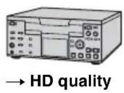
AV device with i.LINK jack

![graph TD A["i.LINK"] --> B["Signal flow"] C["i.LINK"] --> D["i.LINK cable (optional)"] D --> E["HDV/DV"] E --> F["To HDV/DV interface (i.LINK)"] style A fill:#f9f,stroke:#333 style C fill:#f9f,stroke:#333 style E fill:#ccf,stroke:#333 style F fill:#cff,stroke:#333](/content/2026/07/1523711/images/b8f63827479b70435b121b86ee8783cb4c0b334d9c152619bf7f7c57be4411f2.jpg)
* An i.LINK jack which is compatible with HDV1080i specification is required.
Recording movies
1 Set the CAMERA/VCR switch to VCR.
2 Set the input signal of your camcorder.
Set [VCR HDV/DV] to [AUTO] when recording from an HDV format compatible device.
Set [VCR HDV/DV] to [DV] or [AUTO] when recording from a
DVCAM (DV) format compatible device (p. 80).
3 Connect your VCR as a player to your camcorder.
When an i.LINK cable is connected, the format of the input signal (HDVIN LINK or DV will be
indicated on the LCD screen of your camcorder (This indicator may appear on the screen of the playback device but it will not be recorded).
4 Insert a cassette into the VCR.
5 Set your camcorder to recording pause.
While pressing ■ (PAUSE), press both ● REC (record) buttons simultaneously.
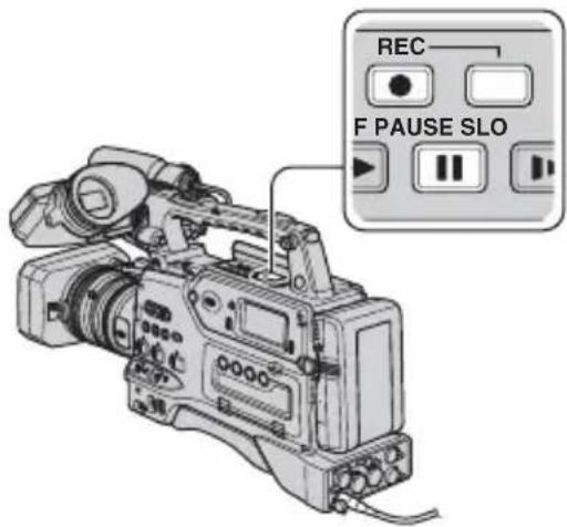
6 Start playing the cassette on your VCR.
The picture played on the VCR appears on the LCD screen of your camcorder.
7 Press II (PAUSE) again at the point you want to start recording.
8 Press ■ (STOP) to stop recording.
Notes
- You cannot record TV programs from the i. HDV/DV interface (i.LINK).
- User bits are not recorded when dubbing from a DVCAM (DV) device via an i.LINK cable.
- You can record pictures from DV devices only in the DVCAM (DV) format.
- Note the following when connecting with an i.LINK cable:
- The recorded picture becomes rough when a picture is paused on your camcorder while recording to a VCR.
- You cannot record the picture and sound separately.
- If you pause or stop the recording and restart it, the picture may not be recorded smoothly.
- If video signals inputted to your camcorder via the HDV/DV jack experience the phenomenon of jittering (variation in frequency), that jittering is transmitted to the video signals outputted from the COMPONENT OUT jack and A/V OUT jack. When you monitor a movie on a TV connected to your camcorder via the COMPONENT OUT jack or A/V OUT jack, images may be distorted or not be displayed. Jittering will not affect recording of the movie on a tape with your camcorder but may affect recording of the movie with another VCR connected to your camcorder via the COMPONENT OUT jack or A/V OUT jack.
Tips
- When a 4:3 video signal is input, it appears with black bands on the right and left sides on the screen of your camcorder.
Recording still images
Be sure to insert a “Memory Stick Duo” for recording in your camcorder beforehand, and assign [PHOTO] to any of ASSIGN buttons (p. 48).
1 Perform steps 1 to 4 in "Recording movies."
Recording pictures from a VCR (Continued)
2 Start playing the cassette.
The pictures on the VCR appear on the screen of your camcorder.
3 Press the ASSIGN button to which [PHOTO] is assigned at the scene you want to record.
Notes
- The image size is 1.2M when capturing a still image from a movie recorded and played back in the HDV format. The image size is 0.2M when capturing a still image from a movie recorded and played back in the DVCAM (DV) and widescreen (16:9) formats, or VGA (0.3M) when the movie is recorded and played back in the DVCAM (DV) and 4:3 formats.
Copying movies on a tape to a computer
Connect your camcorder to the computer with an i.LINK cable.
The computer needs to have an i.LINK connector and be installed with editing software that can copy video signals.
The software required depends on the format of the recorded pictures and the format for copying to the computer (HDV or DVCAM (DV)) as shown in the table below.
| Recorded format | Format for copying to the computer | Required software |
| HDV HDV | Editing software capable of copying HDV signal | |
| HDV | DVCAM (DV) | Editing software capable of copying DVCAM (DV) signal |
| DVCAM (DV) | DVCAM (DV) | Editing software capable of copying DVCAM (DV) signal |
Notes
- The iHDV/DV jack of your camcorder does not have a power-supply function.
- You cannot copy movies using a USB cable.
- Refer to the operating instructions of the software for the details on image copying.
- Refer to the operating instructions of the editing software for the recommended connection.
- Some editing software on the computer may not work correctly.
- You cannot change format DVCAM (DV) to HDV.
The required menu settings vary depending on the recorded images and the format (HDV or DVCAM (DV)) to be copied to the computer.
| Recorded format | Format for copying to the computer | Menu setting* |
| HDV HDV | [VCR HDV/DV] → [HDV] [i.LINK SET] → [HDV → DV CONV] → [OFF] | |
| HDV | DVCAM (DV) | [VCR HDV/DV] → [HDV] [i.LINK SET] → [HDV → DV CONV] → [ON] |
| DVCAM (DV) | DVCAM (DV) | [VCR HDV/DV] → [DV] [i.LINK SET] → [HDV → DV CONV] → [OFF] |
* See page 62 for menu settings.

Tips
• To copy HDV format images as they are without changing their format, an HDV compatible environment is required. For details, refer to your software instruction manual or contact the software manufacturer.
• To play movies by a regular DVD player, you need to create DVD video in the SD format. The DVD video is not in the HDV format.
Step:1 Connect an i.LINK cable
![graph TD A["HDV/DV interface (i.LINK)"] --> B["i.LINK cable (optional)"] B --> C["I.LINK"] D["Computer"] --> C style A fill:#f9f,stroke:#333 style B fill:#ccf,stroke:#333 style C fill:#cfc,stroke:#333](/content/2026/07/1523711/images/146dee4bd4e3f3fc1e3ede2217719071451ae7fb2460358a619b45c4b7fe997d.jpg)
Notes on connecting to the computer
- Connect the i.LINK cable to the computer first, then to your camcorder. Connecting in the opposite order may cause static electricity to build up, resulting in a malfunction of your camcorder.
-
The computer may freeze or may not recognize the signal from your camcorder in the following situations.
-
Connecting your camcorder to a computer that does not support the video signal formats appearing on the LCD screen of your camcorder display (HDV or DVCAM (DV)).
- Changing the settings in [VCR HDV/DV] (p. 80) and [HDV→ DVCONV] of [i.LINK SET] (p. 83).
- Changing [REC FORMAT] setting while connected with an i.LINK cable with the CAMERA/VCR switch set to CAMERA (p. 80).
- Changing the CAMERA/VCR switch position while connected with an i.LINK cable.
- The format (HDV or DVCAM (DV)) of input/output signal appears on the LCD screen of your camcorder while connected with an i.LINK cable.
Step:2 Copying the movies
Use the optional AC Adaptor to obtain AC power (p. 16).
①Prepare editing software (not provided).
②Turn on your computer.
③Insert a tape into your camcorder and set the CAMERA/VCR switch to VCR.
④Set the menu of your camcorder.
The menu settings vary depending on the copying image.
⑤Copy images to the computer with your software.
Notes
- If images are copied in HDV format but are not recognized, your editing software may not support HDV format. Convert the images to DVCAM (DV) format according to step ④ and copy again.
- A tape recorded in DVCAM (DV) format cannot be copied to a computer in HDV format.

Tips
- When images recorded in HDV format are copied to a computer, the file size is about 2GB (almost the same as a DV file) for a 10-minute movie if the video compression format is MPEG2.
When copying the movie in the HDV format from the computer to your camcorder
Set [VCR HDV/DV] to [HDV] and [HDV → DV CONV] of [i.LINK SET] to [OFF] (p. 80, 83).
Notes
- To copy an HDV format movie edited on a computer back onto a tape in HDV format is possible so long as your editing software supports copying HDV movies onto tape. For details, contact the software manufacturer.
When copying the movie in the DVCAM (DV) format from the computer to your camcorder
Set [VCR HDV/DV] to [DV] (p. 80).
Troubleshooting
If you run into any problems using your camcorder, use the following table to troubleshoot the problem. If the problem persists, disconnect the power source and contact your Sony dealer.
• Power sources/LCD screen…p. 97
- Cassette tapes/“Memory Stick Duo”…p. 98
- Recording…p. 98
- Playback…p. 102
- Connecting to TV…p. 103
- Dubbing/Editing/Connecting to other devices…p. 104
- Connecting to a computer…p. 104
Power sources/LCD screen
The power does not turn on or abruptly turns off.
- Attach a charged battery pack to the camcorder (p. 15).
- Use the AC Adaptor to connect to a wall outlet (p. 16).
The camcorder does not operate even when the power is set to on.
- Disconnect the AC Adaptor from the wall outlet or remove the battery pack, then reconnect it after about 1 minute.
- Press the RESET button (p. 125) using a sharp-pointed object.
The camcorder gets warm.
- The camcorder may get warmer while you use it. This is not a malfunction.
The remaining battery time indicator does not indicate the correct time.
- Ambient temperature is too high or too low, or the battery pack has not been charged enough. This is not a malfunction.
- Fully charge the battery again. If the problem persists, the battery may be worn-out. Replace it with a new one (p. 15, 115).
- The indicated time may not be correct in certain circumstances. For example, when you open or close the LCD panel, it takes about 1 minute to display the correct remaining battery time.
- Set proper battery type in [BATTERY TYPE] (p. 90).
The battery pack discharges too quickly.
- Ambient temperature is too high or low, or the battery pack has not been charged enough. This is not a malfunction.
- Fully charge the battery again. If the problem persists, the battery may be worn-out. Replace it with a new one (p. 15, 115).
The picture remains on the LCD screen.
- This occurs if you disconnect the DC plug or remove the battery pack without turning off the power first. This is not a malfunction.
The picture in the viewfinder is not clear.
- Move the viewfinder lens adjustment lever until the picture appears clearly (p. 18).
Cassette tapes/“Memory Stick Duo”
The cassette cannot be ejected from the compartment.
- Make sure the power source (battery pack or AC Adaptor) is connected correctly (p. 15).
- Moisture condensation has occurred inside the camcorder (p. 113).
The Cassette Memory indicator or title display does not appear while using a cassette with Cassette Memory.
- This camcorder does not support Cassette Memory, so the indicator does not appear.
The remaining tape indicator is not displayed.
- Set [REMAINING] to [ON] to always display the remaining tape indicator (p. 80).
You cannot delete pictures or format the "Memory Stick Duo."
- The pictures are protected. Release the protect function on your computer, etc.
Recording
The recording does not start when you press the REC START/STOP button.
- Set the POWER switch to ON and the CAMERA/VCR switch to CAMERA (p. 25).
- The tape has reached the end. Rewind it, or insert a new cassette.
- Set the write-protect tab of the cassette to REC or insert a new cassette (p. 107).
- The tape is stuck to the drum due to moisture condensation. Remove the cassette and leave your camcorder for at least 1 hour, then re-insert the cassette (p. 113).
- Set [REC CTL MODE] of [EXT REC CTRL] to other than [EXT ONLY] (p. 84).
The handle zoom does not work.
- Set the handle zoom speed switch to FIX or VAR (p. 29).
You cannot record on the "Memory Stick Duo."
- Assign [PHOTO] to an ASSIGN button (p. 48).
- The “Memory Stick Duo” is full. Delete unnecessary pictures recorded on the “Memory Stick Duo” (p. 110).
- Format the “Memory Stick Duo” on your camcorder (p. 87) or insert another “Memory Stick Duo” (p. 23).
-
You cannot record still images on the “Memory Stick Duo” in the following cases.
-
While executing [FADER]
- While executing [SMTH SLW REC]
- When the shutter speed is set to slower than 1/60
– While using shot transition - When [SCAN TYPE] is set to [24], [24A] or [30]
You cannot record a smooth transition on a tape from the last recorded scene to the next.
- Do not record progressive pictures in different [REC TYPE] settings on the same tape.
• Perform End search (p. 50). - Do not remove the cassette (the picture will be recorded continuously without a break even when you turn the power off).
- Do not record pictures in the HDV and DVCAM (DV) formats on the same tape.
- Do not record pictures in DVCAM mode and DV SP mode on the same tape.
- When [QUICK REC] is set to [ON], you cannot record a smooth transition (p. 90).


The shutter sound is not heard when you record a still image.
- Set [BEEP] to [ON] (p. 90).
- No shutter sound will be outputted during movie recording or while an external device is connected.
End search or last scene review does not work.
- Do not eject the cassette after recording (p. 50).
- There is nothing recorded on the cassette.
- There is a blank section between recorded sections of the tape. This is not a malfunction.
Auto focus does not function.
- Set the focus ring to mode B and press the ASSIGN button to which [FOCUS] is assigned until the automatic focus function is enabled (p. 30, 48).
- Adjust the focus manually if the automatic focus does not work properly (p. 30).
Menu items are grayed out or do not work.
- You cannot select grayed out display items in the current recording/playback situation.
- There are some functions you cannot activate simultaneously. The following list shows examples of unworkable combinations of functions and menu items.
| Cannot use Situation | |
| [BACK LIGHT], [SPOTLIGHT] | Two or more of iris, gain, and shutter speed are set manually. |
| [AE SHIFT] Iris, gain, and shutter speed are all set manually. | |
| [CNTRST ENHCR] During [BACK LIGHT] | |
| [FADER] No tape is inserted. | |
| [D.EXTENDER] [REC TYPE] of [HDV PROGRE.] is set to [PROGRESSIVE]. [REC TYPE] of [HDV PROGRE.] is set to [INTERLACE] and [SCAN TYPE] is set to [24], [24A] or [30] [SCAN TYPE] of [DV PROGRE.] is set to [24] or [30]. | |
| [ZEBRA], [PEAKING], [CAM DATA DSP], [HISTOGRAM] | The OUTPUT/DCC switch is set to BARS. |
| [SMTH SLW REC] [REC TYPE] of [HDV PROGRE.] is set to [PROGRESSIVE].[REC TYPE] of [HDV PROGRE.] is set to [INTERLACE] and [SCAN TYPE] is set to [24], [24A] or [30].[SCAN TYPE] of [DV PROGRE.] is set to [24] or [30].[REC CTL MODE] of [EXT REC CTRL] is set to [EXT ONLY].The OUTPUT/DCC switch is set to BARS. | |
| [MARKER] During [DATE REC] | |
| [FOCUS MACRO] A Carl Zeiss lens is mounted, and the focus ring is set to mode B.A Carl Zeiss lens is not mounted. | |
| [STEADYSHOT],[FLANGE BACK] | A Carl Zeiss lens is not mounted. |
| [TC LINK] Your camcorder is not connected to an external device via an i.LINK cable. | |
| [TC COUNTUP] [TC MAKE] is set to [REGENERATE]. | |
| [UB-DATE/TC-TIME] [TC MAKE] is set to [REGENERATE].[TC RUN] is set to [REC RUN].[UB TIME REC] is set to [ON].Date and time are not set. | |
| [WORLD TIME], [DATE REC] | Date and time are not set. |
| [x.v.Color] [REC FORMAT] is set to [DV]. | |
| [INTERVAL REC] [REC CTL MODE] of [EXT REC CTRL] is set to [EXT ONLY].[REC TYPE] of [HDV PROGRE.] is set to [PROGRESSIVE].[REC TYPE] of [HDV PROGRE.] is set to [INTERLACE] and [SCAN TYPE] is set to [24], [24A] or [30].[SCAN TYPE] of [DV PROGRE.] is set to [24] or [30]. | |
| [DV FRAME REC] [REC CTL MODE] of [EXT REC CTRL] is set to [EXT ONLY]. | |
| [EXT REC CTRL] During [SMTH SLW REC]During [INTERVAL REC]During [DV FRAME REC] | |
Shutter speed, gain, white balance or iris cannot be adjusted manually.
- Set the CAMERA MODE switch to MANUAL.
Tiny spots in white, red, blue, or green appear on the screen.
- This phenomenon appears when using a slow shutter speed (p. 33). This is not a malfunction.
The subjects passing by the frame very fast appear crooked.
- This is called the focal plane phenomenon. This is not a malfunction. Because of the way that the image device (CMOS sensor) reads out image signals, the subjects passing by the frame rapidly might appear crooked depending on the recording conditions.
The screen picture is bright, and the subject does not appear on the screen.
- Set [BACK LIGHT] to [OFF].
- Set [HYPER GAIN] to [OFF].
The screen picture is dark, and the subject does not appear on the screen.
- Press and hold the DISPLAY button for a few seconds to turn on the backlight (p. 19).
Horizontal stripes appear on the image.
- This occurs when recording pictures under a fluorescent lamp, sodium lamp, or mercury lamp. This is not a malfunction. This can be improved by changing the shutter speed (p. 33).
Black bands appear when you record a TV screen or computer screen.
- This can be improved by adjusting the shutter speed in the ECS mode (p. 33).
The beginning of the recording looks dark when the video light comes on linked to the start of movie recording (when the LIGHT MAN/AUTO switch is set to AUTO).
- The light volume may not be stable immediately after the light comes on.
- The light does not come on during data writing in the cache memory of an external recording unit.
- Set the LIGHT MAN/AUTO switch to MAN and turn on the light before recording starts.
The video light does not come on.
- Set the video light switch to ON.
- The video light does not come on during the following kinds of recording when the LIGHT MAN/AUTO switch is set to AUTO:
- DV frame recording
- Smooth slow recording
- Interval recording
- Recording by a VCR
Fine patterns flicker, diagonal lines look jagged.
- Adjust [DETAIL] to [0] side (p. 42).
Playback
If you are playing back pictures stored on a “Memory Stick Duo,” refer also to the Cassette tapes/“Memory Stick Duo” section (p. 98).
You cannot play back tape.
- Set the POWER switch to ON and the CAMERA/VCR switch to VCR.
- Rewind the tape (p. 55).
Image data stored on a “Memory Stick Duo” cannot be played back correctly.
- Image data cannot be played back if you have modified file names or folders, or have edited the data on a computer (In this case, the file name flashes). This is not a malfunction (p. 111).
- Pictures recorded on other devices may not be played back correctly. This is not a malfunction.
The data file name is displayed incorrectly, or flashing.
- The file is damaged.
- The file format is not supported on your camcorder (p. 107).
- Only the file name is displayed if the directory structure does not conform to the universal standard.
Horizontal lines appear on the picture. The displayed pictures are not clear or do not appear.
- Video head is dirty. Clean the head using the cleaning cassette (optional) (p. 114).
You cannot hear the sound recorded with 4CH microphone recording on your camcorder.
- Confirm the setting of AUDIO MONITOR switch (p. 47).
No sound or only a low sound is heard.
- Turn up the volume (p. 56).
- Pictures recorded using [SMTH SLW REC] do not have sounds.
The picture or sound breaks off.
- The tape was recorded in both of the HDV and DVCAM (DV) formats. This is not a malfunction.
The movies freeze for a while, or the sound breaks off.
- This occurs if the tape or video head is dirty (p. 114).
- Use the Sony standard size DV or mini DV cassette tape.
“---” is displayed on the screen.
- The tape you are playing back was recorded without setting the date and time.
- A blank section on the tape is being played back.
- The data code on a tape with a scratch or noise cannot be read.
- A movie recorded in the extended clear scan (ECS) mode is being played back.
- When a non-Carl Zeiss lens is attached, the iris value cannot be displayed.
- The tape you are playing back was recorded with the gain value set to -6dB.
- The tape you are playing back was recorded with [HYPER GAIN] set to [ON].
Noises appear and por is displayed on the screen.
- The tape was recorded in a TV color system other than that of your camcorder (NTSC). This is not a malfunction.
Date Search does not work correctly.
- Be sure to record more than 2 minutes after the date changed. If one day's recording is too short, your camcorder may not accurately find the point where the recording date changes.
- There is a blank section between recorded sections of the tape. This is not a malfunction.
No picture appears during End search, Rec review or Last scene review.
- The tape was recorded in both HDV and DVCAM (DV) formats. This is not a malfunction.
2/2-ST appears on the LCD screen.
- This appears when you play back a tape recorded on other recording devices using a 4ch microphone.
Connecting to TV
You cannot view the picture on the TV connected with the i.LINK cable.
- You cannot view the picture in the HD (high definition) quality on the TV if an i.LINK jack of the TV is not compatible with the HDV1080i specification (p. 60). Refer to the instruction manuals supplied with your TV.
- Down convert the pictures recorded in HDV format and play back in DVCAM (DV) format (SD image quality) (p. 83).
- Connect the TV with another connecting cable, and play back pictures (p. 60).
You cannot hear the sound on the TV connected with the S VIDEO plug (S VIDEO channel) or component video plug.
- If you are using an S VIDEO plug or component video plug, make sure the audio cable is also connected (p. 60).
You cannot view the picture or hear the sound on the TV connected with the component video cable.
- Set [SDI/CMPNT] according to the requirements of the connected device (p. 82).
You cannot output S video output or video output signals.
- Set the VIDEO OUT switch to COMPOSITE (p. 60).
Dubbing/Editing/Connecting to other devices
Pictures from connected devices cannot be zoomed.
- You cannot zoom pictures from connected devices on your camcorder.
Time code and other information appear on the display of the connected device.
- Set [DISP OUTPUT] to [LCD PANEL] while connected with video and audio cables (p. 80).
You cannot dub correctly using the video and audio cables.
- The video and audio cables are not connected properly. Make sure that the video and audio cable is connected to the input jack of the other device for dubbing a picture from your camcorder.
When connected using an i.LINK cable, no picture appears on the monitor screen during dubbing.
- Set [VCR HDV/DV] according to the requirements of the connected device (p. 80).
You cannot add sound to the recorded tape.
- You cannot add sound to the recorded tape on this unit.
When you copy a movie shot in wide (16:9) format using an i.LINK cable, the screen stretches vertically.
- You cannot output the aspect ratio setting using an i.LINK cable. Set the aspect ratio of the TV instead.
- Connect using video and audio cables instead.
Connecting to a computer
The computer does not recognize your camcorder. i.LINK
- Disconnect the cable from the computer, then connect it again securely.
- Disconnect the cable from the computer, restart the computer, then connect the computer to your camcorder correctly.
You cannot view or copy a movie recorded on a tape to a computer. i.LINK
- Disconnect the cable from the computer, then connect it again.
- You need the editing software (optional) to copy a movie recorded on a tape to your computer (p. 94).
Your computer freezes.
- Set [VCR HDV/DV] correctly according to the connected device (p. 80).
- Disconnect the cable from your computer and camcorder. Reboot your computer, and connect your computer and camcorder following the steps in the correct order (p. 95).
Warning indicators and messages
Self-diagnosis display/Warning indicators
When an error occurs, a warning indicator appears on the LCD screen or in the viewfinder, or the WARNING lamp turns on or flashes.
You can fix some problems associated with the symptoms yourself. If the problem persists even after you have tried a couple of times, contact your Sony dealer or local authorized Sony service facility.
C:(or E:) □□:□□ (Self-diagnosis display)
C:21:□□
- Moisture condensation has occurred. Remove the cassette and leave your camcorder for at least 1 hour, then re-insert the cassette (p. 113).
C:22:□□
- Clean the head using a cleaning cassette (optional) (p. 114).
C:31:□□ / C:32:□□
- Symptoms that are not described above have occurred. Remove and insert the cassette, then operate your camcorder again. Do not perform this procedure if moisture condensation has occurred (p. 113). - Remove the power source. Reconnect it and operate your camcorder again. - Change the cassette. Press the RESET button (p. 125), and operate your camcorder again.
E:61:□□ / E:62:□□
- Contact your Sony dealer or local authorized Sony service facility. Inform them of the 5-digit code, which starts from “E.”
101-1001(Warning indicator pertaining to files)
- The file is damaged.
- The file is unreadable (p. 111).
(Battery level warning)
• The battery pack is nearly used up.
- Depending on the operating, environment, or battery conditions, may flash, even if there are approximately 5 to 10 minutes remaining.
(Moisture condensation warning)*
- Eject the cassette, remove the power source, and then leave it for about 1 hour with the cassette lid open (p. 113).
Warning indicators pertaining to the tape)
Slow flashing:
- There is less than 5 minutes remaining on the tape.
- No cassette is inserted.*
- The write-protect tab on the cassette is set to lock (p. 107).*
Fast flashing:
- The tape has run out.*
▲ (Eject cassette warning)*
Slow flashing:
- The write-protect tab on the cassette is set to lock (p. 107).
Fast flashing:
- Moisture condensation has occurred (p. 113).
- The self-diagnosis display code is displayed (p. 106).
Warning messages
If messages appear on the screen, follow the instructions.
Maintenance and precautions
HDV format and recording/ playback
Your camcorder is capable of recording in HDV/DVCAM/DV formats.
It is recommended to use a cassette with the DV or MIN mark to record in the HDV/DVCAM/DV format.
It is recommended to use a cassette with the DVCAM mark to record in the DVCAM format.
Your camcorder is not compatible with the Cassette Memory function.
What is the HDV format?
The HDV format is a video format developed to record and play back digital high definition (HD) video signals on a DV cassette.
Your camcorder adopts the Interlace mode with 1,080 effective scan lines of screen ruling (1080i, number of pixels 1,440 × 1,080 dots).
The video bit rate for recording is about 25 Mbps.
i.LINK is adopted for the digital interface, enabling a digital connection with an HDV compatible TV or computer.
- HDV signals are compressed in MPEG2 format, which is adopted in BS (broadcast satellite) digital, terrestrial digital HDTV broadcastings, in Blu-ray Disc recorders, etc.
Playback
- Your camcorder can play back pictures in both the DVCAM (DV) format and HDV1080i specification.
- Your camcorder can play back pictures recorded in the HDV 720/30p format, but cannot output it from the HDV/DV interface (i.LINK).
To prevent a blank section from being created on the tape
Go to the end of the recorded section using [END SEARCH] (p. 50) before you begin the next recording when you have played back the tape.
Copyright signal
■ When you play back
If the cassette you play back on your camcorder contains copyright signals, you cannot copy it to a tape in another video camera connected to your camcorder.
When you record
You cannot record software on your camcorder that contains copyright control signals for copyright protection of software. [Cannot record due to copyright protection.] appears on the LCD screen, or on the viewfinder if you try to record such software. Your camcorder does not record copyright control signals on the tape when it records.
Audio mode
The DVCAM format has 2 audio modes.
- You cannot dub sound onto a recorded tape with your camcorder.
■ FS32K (12-bit) mode
Sound can be recorded in four 4 channels, CH1, CH2, CH3 and CH4.
You can monitor sounds by switching outputs using the AUDIO MONITOR switch. When the AUDIO MONITOR switch is set to MIX, CH1 and CH3 sounds are mixed and CH2 and CH4 sounds are mixed.
■ FS48K (16-bit) mode
The original sound can be recorded in high quality using 2 channels. The audio mode can be indicated on the LCD screen or in the viewfinder.
Notes on use
■ When not using your camcorder for a long time
Remove the cassette and store it.
Maintenance and precautions (Continued)
■ To prevent accidental erasure
Slide the write-protect tab on the cassette to set it to SAVE.

REC: The cassette can be recorded.
SAVE: The cassette cannot be recorded (write-protected).
■ When labeling the cassette
Be sure to place the label only on the locations shown in the following illustration so as not to cause a malfunction of your camcorder.
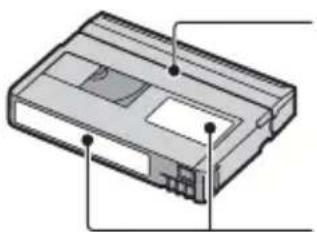
Do not put a label along this border.
Labeling position
■ After using the cassette
Rewind the tape to the beginning to avoid distortion of the picture or the sound. The cassette should then be put in its case, and stored in an upright position.
■ When cleaning the gold-plated connector
Generally, clean the gold-plated connector on a cassette with a cotton-wool swab after every 10 times it has been ejected. If the gold-plated connector on the cassette is dirty or dusty, the remaining tape indicator may not show correctly.

Gold-plated connector
On Sony HDV1080i compliant TVs
HDV1080i
An HDV format compatible TV with the component input jack is required to view playback pictures recorded in the HDV format.
Compatibility of the DVCAM/DV formats
The DVCAM format was developed as a more reliable and higher-end format than the consumer DV format. Explained here are the differences, compatibility, and limitations on editing for the DVCAM and DV formats.
Differences between the DVCAM and DV formats
| Specification DVCAM DV | ||
| TRACK Pitch | 15 μm 10 μm | |
| Audio sampling frequency | 12 bit:32 kHz | 12 bit:32 kHz |
| 16 bit:48 kHz | ||
| 16 bit:48 kHz | 44.1 kHz | |
| 48 kHz | ||
| Audio recording mode* | Lock mode Lock/Unlock mode | |
* There are 2 modes for audio recording, lock mode and unlock mode. In lock mode, the sampling frequencies of audio and video are synchronized. Therefore, lock mode is more effective than unlock mode in digital processing and smooth transition during audio editing.
The recording format of the picture is defined according to the recorder's format as described below.
| Recorder's format | Cassette's format | Recording format |
| DVCAM | DVCAMDV | DVCAM |
| DV | DVCAMDV | DV |
Notes
- This camcorder complies with the DVCAM format. Though mini DV cassettes can be used for recording, we recommend you use mini DVCAM cassettes to get the most out of the high reliability of the DVCAM format.
- The recording time of mini DV cassettes is 1/3 shorter than that indicated on mini DV cassettes when recorded in the DVCAM format.
Compatibility on playback
| Tape On DV video equipment | On DVCAM video equipment | |
| DV formatted | Can be playback | Can be played back only when recorded in SP mode |
| DVCAM formatted | Can be played back on some equipment | Can be playback |
Compatibility on editing using DV jacks
When this camcorder is connected to other digital video equipment using an i.LINK cable, the recording format of edited tapes is defined according to the source tape and the recorder's format as described below. Playback or editing using the edited tape may be limited depending on dubbing operation. Start dubbing after reading “Limitations on editing” (p. 110).
| Source tape | Player's format | Recorder's format | Recording format |
| DV formatted (SP mode only) | DVCAM | DVCAM | DV DV1) |
| DV formatted | DV DVCAM | DVCAM | |
| DV DV | |||
| DVCAM formatted2) | DVCAM | DVCAM | DVCAM |
| DV DV | |||
| DVCAM formatted2) | DV3) | DVCAM | DVCAM(Compatibility depends on models.) |
| DV DV |
1) When using mini DVCAM video equipment to perform DV dubbing of a tape recorded in DV format, the tape produced will be in the DVCAM format which the time code format will be partly misadjusted. (there will be no effect on the recorded picture except in certain cases.)
2) If the tape that is to be dubbed is in the DVCAM format as in 1), the tape produced will be in the DVCAM format and the time code format will be partly misadjusted.
3) Some mini DV video equipment may be able to play back a DVCAM-formatted tape. Even if the tape is played back, quality of the playback cannot be guaranteed. The time code format will be partly misadjusted.
Maintenance and precautions (Continued)
Notes
- If you use tapes as in 1) to 3) above for editing, the functions may be limited regardless of the format of players and recorders.
Limitations on editing
You may find the following limitations when editing a tape produced by dubbing or editing using the HDV/DV Interface
i (i.LINK) jack:
- Due to the difference in track pitch, you cannot record or edit on DV-formatted tapes using mini DVCAM video equipment.
- Depending on the DVCAM video equipment used, you may not be able to edit DVCAM formatted tapes if the audio recording mode is unlock mode. In this case, dub using audio/video jacks.
About the "Memory Stick"
A “Memory Stick” is a compact, portable IC recording medium with a large data capacity.
You can use the following types of “Memory Stick” listed below on the camcorder. However, we do not guarantee the operation of all types of “Memory Stick” on your camcorder. (See the list below for more details.)
| Types of “Memory Stick” | Recording /Playback |
| “Memory Stick Duo” (with MagicGate) | ○ |
| “Memory Stick PRO Duo” | ○ |
| “Memory Stick PRO-HG Duo” | ○ |
- This product does not support high speed data transfer via a parallel interface.
- This product cannot record or play data that uses “MagicGate” technology. “MagicGate” is a copyright protection technology that records and transfers the contents in an encrypted format.
-
This product is compatible with “Memory Stick Micro” (“M2”). “M2” is the abbreviation for the “Memory Stick Micro.”
-
Still image format: Your camcorder compresses and records image data in the JPEG (Joint Photographic Experts Group) format. The file extension is “.JPG.”
- A “Memory Stick Duo” formatted by a computer (Windows OS/Mac OS) does not have guaranteed compatibility with your camcorder.
- Data read/write speed may vary depending on the combination of the “Memory Stick Duo” and “Memory Stick Duo” compliant product you use.
- You can prevent accidental erasure of images when you slide the write-protect tab on the “Memory Stick Duo” with a small tapered object, to the write-protect position.
- Damaged or lost image data will not be compensated for, and may occur in the following cases:
- If you eject the “Memory Stick Duo,” turn the power off on your camcorder, or remove the battery pack for replacement while your camcorder is reading or writing image files on the “Memory Stick Duo” (while the access lamp is lit or flashing).
- If you use the “Memory Stick Duo” near magnets or magnetic fields.
- It is recommended to make a back-up of important data on the hard disk of a computer.
- Be careful not to apply excessive force when writing on a memo area on a “Memory Stick Duo.”
- Do not attach a label or the like on a “Memory Stick Duo” or a Memory Stick Duo adaptor.
- When you carry or store a “Memory Stick Duo,” put it in its case.
- Do not touch, or allow metallic objects to come into contact with the terminals.
- Do not bend, drop or apply strong force to the "Memory Stick Duo."
- Do not disassemble or modify the “Memory Stick Duo.”
- Do not let the “Memory Stick Duo” get wet.
- Be careful to keep “Memory Stick Duo” media out of the reach of small children. There is danger that a child might swallow it.
- Do not insert anything other than a “Memory Stick Duo” into the Memory Stick Duo slot. Doing so may cause a malfunction.
- Do not use or keep the “Memory Stick Duo” in the following locations:
- Places subject to extremely high temperature, such as a car parked outside in the summer.
- Places under direct sunlight.
- Places with extremely high humidity or subject to corrosive gases.
■ On the Memory Stick Duo adaptor
- When using a “Memory Stick Duo” with a “Memory Stick” compliant device, make sure to insert the “Memory Stick Duo” into a Memory Stick Duo adaptor.
- When inserting a “Memory Stick Duo” into a Memory Stick Duo adaptor, make sure the “Memory Stick Duo” is inserted facing in the correct direction, then insert it all the way in. Note that improper use may cause a malfunction. Also, if you force the “Memory Stick Duo” into the Memory Stick Duo adaptor in the wrong direction, it may be damaged.
- Do not insert a Memory Stick Duo adaptor without a “Memory Stick Duo” attached. Doing so may result in malfunctions of the unit.
On a "Memory Stick PRO Duo"
- The maximum memory capacity of a “Memory Stick PRO Duo” that can be used on your camcorder is 8 GB.
Notes on using "Memory Stick Micro"
- To use a “Memory Stick Micro” with the camcorder, you need a Duo-sized M2 Adaptor. Insert the “Memory Stick Micro” into the Duo-sized M2 Adaptor, then insert the adaptor into the Memory Stick Duo slot. If you insert a “Memory Stick Micro” into the camcorder without using a Duo-sized M2 Adaptor, you might not be able to remove it from the camcorder.
- Do not leave the “Memory Stick Micro” within the reach of small children. They might accidentally swallow it.
On image data compatibility
- Image data files recorded on a “Memory Stick Duo” by your camcorder conform to the “Design rule for Camera File system” universal standard established by the JEITA (Japan Electronics and Information Technology Industries Association).
- On your camcorder, you cannot play back still images recorded on other devices (DCR-TRV900 or DSC-D700/D770) that do not conform to the universal standard. (These models are not sold in some regions.)
- If you cannot use a “Memory Stick Duo” that has been used with another device, format it with your camcorder (p. 87). Note that formatting erases all information on the “Memory Stick Duo.”
- You may not be able to play back images with your camcorder:
- When playing back image data modified on your computer.
- When playing back image data recorded with other devices.
About storage of the battery pack
- If the battery pack is not used for a long time, fully charge the battery pack and use it up on your camcorder once a year to maintain proper function. To store the battery pack, remove it from your camcorder and put it in a dry, cool place.
- To discharge the battery pack on your camcorder completely, leave your camcorder in tape recording standby until the power goes off (p. 15).
About battery life
- Battery capacity decreases over time and through repeated use. If decreased usage time between charges becomes significant, it is probably time to replace it with a new one.
- Each battery's life is governed by storage, operating and environmental conditions.
About i.LINK
The iHDV/DV (i.LINK) jack on your camcorder is an i.LINK-compliant 6-pin jack. This section describes the i.LINK standard and its features.
What is i.LINK?
i.LINK is a digital serial interface for transferring digital video, digital audio, and other data to other i.LINK-compatible devices. You can also control other devices using the i.LINK.
i.LINK-compatible devices can be connected using an i.LINK cable. Possible applications are operations and data transactions with various digital AV devices.
When two or more i.LINK-compatible devices are daisy-chained with the unit, operation becomes possible from any device in the chain. Note that operation method may vary, or data transactions may not be possible, depending on specifications and characteristics of the connected devices.
Notes
- Normally, only one device can be connected to this unit with an i.LINK cable. When connecting this unit to an HDV/DV compatible device having two or more HDV/DV interfaces, refer to the operating instructions of the device to be connected.
- i.LINK is a more familiar term for the IEEE 1394 data transport bus proposed by Sony, and is a trademark approved by many corporations.
- IEEE 1394 is an international standard standardized by the Institute of Electrical and Electronics Engineers.
About the i.LINK Baud rate
i.LINK's maximum baud rate varies according to the device. There are 3 types.
S100 (approx. 100Mbps * ) S200 (approx. 200Mbps) S400 (approx. 400Mbps)
The baud rate is listed under “Specifications” in the operating instructions of each piece of equipment. It is also indicated near the i.LINK interface on some devices.
The baud rate may differ from the indicated value when the unit is connected to a device with a different maximum baud rate.
* What is Mbps?
Mbps stands for “megabits per second,” or the amount of data that can be sent or received in one second. For example, a baud rate of 100 Mbps means that 100 megabits of data can be sent in one second.
To use i.LINK functions on this unit
For details on how to dub when this unit is connected to other video devices having an i.LINK interface, see page 95. This unit can also be connected to other i.LINK-compatible devices made by Sony (for example, a VAIO series personal computer) as well as to video devices. Some i.LINK compatible video devices, such as Digital Televisions, DVD, MICROMV or HDV recorders/players are not compatible with this unit. Before connecting to other devices, be sure to confirm whether the device is compatible with an HDV/DV device or not. For details on precautions and compatible application software, refer also to the operating instructions for the device to be connected.
Notes
- When connecting a device with an i.LINK terminal to your camcorder via an i.LINK cable, switch off the device and unplug it from the power socket before plugging in or unplugging the i.LINK cable.
About x.v.Color
- x.v.Color is a more familiar term for the x.v.YCC standard proposed by Sony, and is a trademark of Sony.
- x.v.YCC is an international standard for color space in video. This standard can express a wider color range than the currently used broadcast standard.
About handling of your camcorder
On use and care
- Do not use or store the camcorder and accessories in the following locations.
– Anywhere extremely hot or cold. Never leave them exposed to temperatures above 60\ °C ( 140\ °F ), such as under direct sunlight, near heaters or in a car parked in the sun. They may malfunction or become deformed.
– Near strong magnetic fields or mechanical vibration. The camcorder may malfunction. - Near strong radio waves or radiation. The camcorder may not be able to record properly.
- Near AM receivers and video equipment. Noise may occur.
- On a sandy beach or anywhere dusty. If sand or dust gets in your camcorder, it may malfunction. Sometimes this malfunction cannot be repaired.
- Near windows or outdoors, where the LCD screen, the viewfinder, or the lens may be exposed to direct sunlight. This damages the inside of the viewfinder or the LCD screen.
-
Anywhere very humid.
-
Operate your camcorder on DC 7.2 V (battery pack) or DC 8.4 V (AC Adaptor).
- For DC or AC operation, use the accessories recommended in these operating instructions.
- Do not let your camcorder get wet, for example, from rain or sea water. If your camcorder gets wet, it may malfunction. Sometimes this malfunction cannot be repaired.
- If any solid object or liquid gets inside the casing, unplug your camcorder and have it checked by a Sony dealer before operating it any further.
- Avoid rough handling, disassembling, modifying, physical shock, or impact such as hammering, dropping or stepping on the product. Be particularly careful of the lens.
- Keep the POWER switch setting to OFF when you are not using your camcorder.
- Do not wrap your camcorder with a towel, for example, and operate it. Doing so might cause heat to build up inside.
-
When disconnecting the power cord, pull it by the plug and not the lead.
-
Do not damage the power cord such as by placing anything heavy on it.
- Keep metal contacts clean.
- If the battery electrolytic liquid has leaked,
– consult your local authorized Sony service facility.
- wash off any liquid that may have contacted your skin.
- if any liquid gets in your eyes, wash with plenty of water and consult a doctor.
■ When not using your camcorder for a long time
- Periodically turn on the camcorder and play a cassette for about 3 minutes.
- Use up the battery pack completely before storing it.
Moisture condensation
If your camcorder is brought directly from a cold place to a warm place, moisture may condense inside your camcorder, on the surface of the tape, or on the lens. In this state, the tape may stick to the head drum and be damaged or your camcorder may not operate correctly. If there is moisture inside your camcorder, [Moisture condensation. Eject the cassette] or [Moisture condensation. Turn off for 1H.] appears. The indicator will not appear when the moisture condenses on the lens.
■ If moisture condensation has occurred
None of the functions except cassette ejection will work. Eject the cassette, turn off your camcorder, and leave it for about one hour with the cassette lid open. Your camcorder can be used again when both of the following conditions are met:
- The warning message does not appear when the power is turned on.
- Neither ☐ nor ▲ flashes when a cassette is inserted and the video operation buttons are pressed.
If moisture starts to condense, your camcorder sometimes cannot detect condensation. If this happens, the cassette is sometimes not ejected for 10 seconds after the cassette lid is opened. This is not a
©
Cleaning Kit (optional), do not apply the cleaning liquid directly to the LCD screen. Use cleaning paper moistened with the liquid.
On handling the casing
- If the casing is soiled, clean the camcorder body with a soft cloth lightly moistened with water, and then wipe the casing with a dry soft cloth.
- Avoid the following to avoid damage to the finish.
- Using chemicals such as thinner, benzine, alcohol, chemical cloths, repellent, insecticide and sunscreen.
– Handling with above substances on your hands. - Leaving the casing in contact with rubber or vinyl objects for a long period of time.
About care and storage of the lens
- Wipe the surface of the lens clean with a soft cloth in the following instances:
- When there are fingerprints on the lens surface.
– In hot or humid locations - When the lens is exposed to salty air such as at the seaside.
- Store in a well-ventilated location subject to little dirt or dust.
• To prevent mold, periodically clean the lens as described above. It is recommended that you operate your camcorder about once a month to keep it in optimum state for a long time.
On charging the pre-installed rechargeable battery
Your camcorder has a pre-installed rechargeable battery to retain the date, time, and other settings even when the POWER switch is set to OFF. The pre-installed rechargeable battery is always charged while your camcorder is connected to the wall outlet via the AC Adaptor or while the battery pack is inserted. The rechargeable battery will be fully discharged in about 3 months if you do not use your camcorder at all without the AC Adaptor connected or the battery pack attached. Use your camcorder after charging the pre-installed rechargeable battery.
However, even if the pre-installed rechargeable battery is not charged, the camcorder operation will not be affected as long as you are not recording the date.
Procedures
Connect your camcorder to a wall outlet using the optional AC Adaptor, and leave it with the POWER switch set to OFF for more than 24 hours.
Removing dust from inside the viewfinder
1 Remove the eye piece of the viewfinder.
Push and hold the RELEASE buttons in the eye piece of the viewfinder (①), and remove the eye piece (②).

2 Remove dust inside the eye piece and viewfinder with a blower.
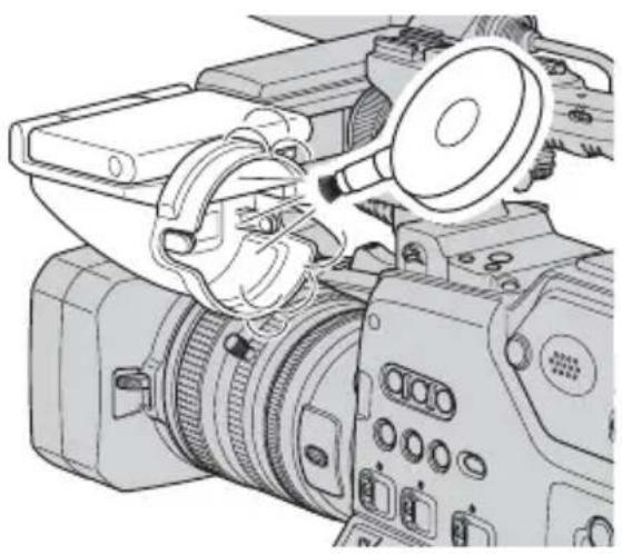
Specifications
System
Video recording system (HDV)
2 rotary heads, Helical scanning system
Video recording system (DVCAM (DV))
2 rotary heads, Helical scanning system
Still image recording system
Exif Ver. 2.2*
Audio recording system (HDV)
Rotary heads,
MPEG-1 Audio Layer-2 (2-channel)
MPEG-2 Audio Layer-2 (4-channel)
Quantization: 16 bits
Fs48kHz (stereo)
transfer rate: 384 kbps
Audio recording system (DVCAM (DV))
Rotary heads, PCM system
Quantization: 12 bits
Fs32kHz (channel 1/2, channel 3/4
stereo)
Quantization: 16 bits
Fs48kHz (channel 1/2 stereo)
Video signal
NTSC color, EIA standards
1080/60i specification
Usable cassette
Standard size DV cassette with the

Standard size DVCAM cassette with
the Dmark printed
Mini DV cassette with the Mini mark
printed
Mini DVCAM cassette with the DVCAM
mark printed
Tape speed (HDV)
Approx. 18.812 mm/s
Tape speed (DVCAM)
Approx. 28.218 mm/s
Tape speed (DV SP)
Approx. 18.812 mm/s
Recording/playback time (HDV)
276 min (using a PHDV-276DM cassette)
63 min (using a PHDVM-63DM cassette)
Recording/playback time (DVCAM)
184 min (using a PHDV-276DM cassette)
41 min (using a PHDVM-63DM cassette)
Recording/playback time (DV SP)
276 min (using a PHDV-276DM cassette)
63 min (using a PHDVM-63DM cassette)
Fast forward/rewind time
Approx. 2 min (using a PHDV-276DM cassette and rechargeable battery pack)
Approx. 2 min (using a PHDV-276DM cassette and AC Adaptor)
Viewfinder
Electric viewfinder (color, black and white)
Picture 1.1 cm (0.45 type, aspect ratio 16:9)
Total dot number
1 226 880 (approx. 852 × 3[RGB] × 480 )
Image device
6.0 mm (1/3 type) 3CMOS sensor
Recording Pixels (HDV/DV16:9 still recording):
Max. 1.20 Mega (1 440 × 810) pixels**
Gross: Approx. 1 120 000 pixels
Effective (movie, 16:9):
1 037 000 pixels
Effective (movie, 4:3):
778 000 pixels
Effective (still, 16:9):
1 037 000 pixels
Effective (still, 4:3):
778 000 pixels
Specifications (Continued)
Lens
Carl Zeiss Vario-Sonnar T*
12 × (Optical), Approx. 18 × (Digital, when [D.EXTENDER] is set to [ON])
Focal length
f=4.4 - 52.8 mm (3/16 - 2 1/8 in.)
When converted to a 35 mm still camera
32.0 - 384 mm (1 5/16 - 15 1/8 in.)
(16:9),
39.5 - 474 mm (1 9/16 \~ 18 3/4 in.)
(4:3)
F1.6 - 2.0
Filter diameter: 72 mm (2 7/8 in.)
Color temperature
[AUTO]
[ONE PUSH AF]
[INDOOR] (3 200K)
[OUTDOOR] (5 800K±7 offset levels)
[MANU WB TEMP] (2 300K -
15 000K in 100K steps)
Minimum illumination
1.5 lx (lux) (Fixed Shutter Speed 1/30, auto gain, auto iris) (F 1.6)
* “Exif” is a file format for still images, established by the JEITA (Japan Electronics and Information Technology Industries Association). Files in this format can have additional information such as your camcorder’s setting information at the time of recording.
**Still image resolution is obtained by the unique pixel array of Sony's ClearVid CMOS Sensor and image processing system (new Enhanced Imaging Processor).
Output connectors
VIDEO OUT jack
BNC connector × 1
Video signal: 1 Vp-p, 75 Ω (ohms)
SVIDEO jack
S connector × 1
Luminance signal: 1 Vp-p, 75 Ω (ohms)
Chrominance signal: 0.286 Vp-p (burst signal), 75 Ω (ohms)
AUDIO OUT jack
RCA connector × 2
Audio signal: -10 dBu (at load
impedance 47 kΩ (kilohms)), Output
impedance with less than 2.2 kΩ
(kilohms)
(0 dBu=0.775 Vrms)
TC OUT jack
BNC connector × 1
2.2 Vp-p, 600 Ω (ohms) / 1.2 Vp-p,
75 Ω (ohms)
COMPONENT OUT jack
BNC connector × 3
Y: 1 Vp-p, 75Ω (ohms), PB/PR, CB/CR:
+/- 350 mV, 75 Ω (ohms)
HD/SD SDI OUT jack
BNC type × 1
SD-SDI: SD-SDI format,
SMPTE259M-C (270Mbps)
HD-SDI: HD-SDI format,
SMPTE292M
Input/Output connectors
LANC jack
Stereo mini-minijack (∅ 2.5 mm)
AUDIO INPUT1 (L)/AUDIO INPUT2
(R)/AUDIO INPUT3/AUDIO INPUT4
jack
XLR 3-pin, female,
-48 dBu: 3kΩ(kilohms)
+4 dBu: 10kΩ(kilohms)
(0 dBu=0.775 Vrms)
PHONES jack
Stereo-minijack (∅3.5 mm)
DC OUT 12V connector
4-pin, male, 12 V
LIGHT connector
2-pin, max. 35 W
LENS jack
12-pin connector
i HDV/DV jack
i.LINK interface (IEEE 1394, 6-pin connector S100)
DC IN 12V connector
XLR 4-pin, female, 11 V - 17 V
LCD screen
Picture
8.0 cm (3.2 type, aspect ratio 16:9)
Total dot number
921 600 (1 920 × 480)
General
Power requirements
DC 14.4 V (battery pack)
DC 12 V (11 V - 17 V) (AC Adaptor)
Average power consumption*
During camera recording using the viewfinder with normal brightness:
HDV recording 12.5 W
DVCAM (DV) recording 11.9 W
During camera recording using the viewfinder and Memory Recording
Unit (HVR-MRC1) with normal brightness:
HDV recording 15.1 W
DVCAM (DV) recording 14.6 W
Operating temperature
0°C to 40°C (32°F to 104°F)
Storage temperature
-20°C to +60°C (-4°F to +140°F)
Dimensions (approx.)
305 × 277 × 505 mm
(11 1/8 × 11 × 20 in.) (w/h/d)
including the projecting parts with Carl
Zeiss lens (VCL-412BWS) and lens hood with lens cover
305 × 277 × 510 mm
(11 1/8 × 11 × 20 1/8 in.) (w/h/d)
including the projecting parts with Carl Zeiss lens (VCL-412BWS), lens hood with lens cover and battery pack (BP-GL65)
Mass (approx.)
4.0 kg (8 lb 12 oz) camera body only
5.2 kg (11 lb 7 oz) including Carl Zeiss lens (VCL-412BWS)
6.3 kg (13 lb 15 oz) including battery pack (BP-GL95), cassette (PHDV-276DM), Carl Zeiss lens (VCL-
412BWS), lens hood with lens cover and microphone (ECM-XM1)
* When the microphone (ECM-XM1) is used
Design and specifications are subject to change without notice.
On trademarks
- “Memory Stick,” “” Memory Stick Duo,” “” Memory Stick
PRO Duo," "MEMORY STICK PRO Duo
"Memory Stick PRO-HG Duo,"
"MEMMORYSTICK-HG Duo
Micro," "MagicGate," "MAGICGATE
"MagicGate Memory Stick" and "MagicGate Memory Stick Duo" are trademarks of Sony Corporation.
• "x.v.Color" is a trademark of Sony Corporation.
• i.LINK and are trademarks of Sony Corporation.
• DV Digital Video Cassette Mini DV Digital Video Cassette
• is a trademark.
- Microsoft, Windows, Windows Vista, and Windows Media are trademarks or registered trademarks of U.S. Microsoft Corporation in the U.S. and other countries.
• Macintosh and Mac OS are registered trademarks of Apple Inc. in the U.S. and other countries.
• HDV and the HDV logo are trademarks of Sony Corporation and Victor Company of Japan, Ltd.
- Pentium is a trademark or registered trademark of Intel Corporation.
- Adobe, and Adobe Reader are trademarks of Adobe Systems Incorporated.
All other product names mentioned herein may be the trademarks or registered trademarks of their respective companies. Furthermore, TM and “®” are not mentioned in each case in this manual.
Notes on the License
ANY USE OF THIS PRODUCT OTHER THAN CONSUMER PERSONAL USE IN ANY MANNER THAT COMPLIES WITH THE MPEG-2 STANDARD FOR ENCODING VIDEO INFORMATION FOR PACKAGED MEDIA IS EXPRESSLY PROHIBITED WITHOUT A LICENSE UNDER APPLICABLE PATENTS IN THE MPEG-2 PATENT PORTFOLIO, WHICH LICENSE IS AVAILABLE FROM MPEG LA, L.L.C., 250 STEELE STREET, SUITE 300, DENVER, COLORADO 80206.
are
trademarks.
Identifying parts and controls
The numbers in ( ) are reference pages.

1 Accessory shoe (127)
②Shoulder strap fitting (12)
3 Handle zoom lever (29)
4REC START/STOP button (25)
5 Microphone holder (11)
6 Microphone fixing clamper (11)
7 LIGHT connector (2-pin, female) (27)
A video light with a maximum power consumption of 35W, such as the Anton Bauer Ultralight 2 or equivalent can be connected.
8LENS jack (9)
9 Microphone (11)
10 Iris ring (32)
11 Zoom ring (29)
12 Focus ring (30)
13 Lens hood with lens cover (11)
14 Lens (9)
15 PUSH AUTO button (32)
16 IRIS switch (32)
17 Zoom lever (31)
18 REC REVIEW/L2 button (50)
19 AUDIO OUT jacks (60)
20VIDEO OUT jack (60)
21COMPONENT OUT jacks (60)
22TC OUT jack (60)
23 Cover (13) Remove this cover when you attach the Memory Recording Unit HVR-MRC1.
24 HDV/DV jack (60)
25 HDV/DV jack cover
26 Accessory interface shoe (13)
Identifying parts and controls (Continued)
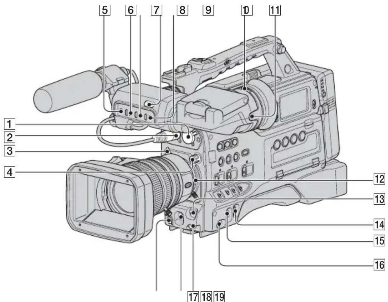
1 AUDIO INPUT2 (R) jack (45)
② AUDIO INPUT1 (L) jack (45)
3 Lens mount securing tab (9)
4ND filter (32)
5 TALLY switch Set to ON to turn on the front recording lamp.
6PEAKING switch (18)
7 LIGHT ON/OFF switch
Lights the lens to help you to see the focus scale in the dark.
8 Recording lamp (25)
9VIDEO OUT switch (60)
10 Viewfinder lens adjustment lever (18)
11RELEASE button (115)
12 Lens mount (9)
13 SHUTTER switch (33)
14 SEL/PUSH EXEC dial (20)
15 CAMERA/VCR switch (17)
16 POWER switch (17)
17 AUDIO LEVEL dial
Adjusts the audio input level of CH1.
18 WHT/BLK switch (34)
19 REC START/STOP button (25)

1 LIGHT MAN/AUTO switch
Select AUTO or MAN to automatically or manually turn on and off a video light connected to the LIGHT connector.
AUTO: The video light automatically turns on upon a start of recording when its power switch is in the on position.
MAN: You can manually turn on and off the video light with its power switch.
② DIGITAL EXTENDER/L1 button (48)
3 Lens cover lever (12)
4 AGC switch (33)
5 GAIN switch (33)
6 OUTPUT/DCC switch
Switches the video signal, which is output to the VTR part, viewfinder, and video monitor from the camera part, between the following two.
BARS: Outputs the color bar signal.
CAM: Outputs the video signal from the camera. When this is selected, you can switch DCC* on and off.
* DCC (Dynamic Contrast Control): Against a very bright background with the iris opening
adjusted to the subject, objects in the background will be lost in the glare. The DCC function will suppress the high intensity and restore much of the lost detail and is particularly effective in the following cases.
• Recording people in the shade on a sunny day
- Recording a subject indoors, against a background through a window
• Any high contrast scene
OUTPUT: CAM, DCC: ON
The video signal from the camera is output, and the DCC circuit operates.
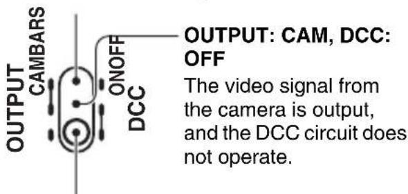
OUTPUT: BARS, DCC: OFF
A color bar signal is output and the DCC circuit does not operate. Use this setting to adjust the video monitor, to record the color bar signal, etc.
Identifying parts and controls (Continued)
7WHT BAL switch (33)
8MENU/STATUS switch (62)
9 SHOT TRANSITION/FOCUS MARKING button (51)
10 A button (51)
11B button (51)
12Handle zoom switch (29)
13Shoulder strap fitting (12)
14 ASSIGN 1-3 buttons (48)
15 ASSIGN 4 button/ZEBRA button (48)
16 ASSIGN 5 button/AE SHIFT button (48)
17PICTURE PROFILE button (36)
18 ASSIGN 6 button/STEADYSHOT button (48)
19ATW switch (34)
20 CAMERA MODE switch (32)

Built-in speaker
The speaker can be used to monitor E-E* sound during recording, and playback sound during playback. The speaker also sounds alarms to reinforce visual warnings. If you connect earphones to the PHONES jack, the speaker is automatically muted.
* E-E: Abbreviation of “Electric-to-Electric.” In E-E mode, video and audio signals input to the camcorder are output after passing through internal electric circuits only. This can be used to check input signals.
2 MONITOR dial (56)
3 Sub LCD panel (131)
4 LCD BACK LIGHT switch
When you set the switch to ON, the backlight of the sub LCD screen turns on.
5 DATA CODE button (58)
⑥ Video control buttons (STOP/REW/PLAY/FF/PAUSE/REC/SLOW/CUE/REVIEW) (55)
7 PHONES jack
Plugging earphones into the jack
automatically cuts off the sound from built-in speaker.
8 TC/U-BIT button
Switches between time code and user bit to display on the sub LCD screen (display on the LCD screen also changes).
9 WARNING lamp (106)
10 AUDIO LEVEL DISPLAY switch
Switches between CH1/CH2 and CH3/CH4 audio level meters to display on the sub LCD screen (display on the LCD screen also changes).
11 Battery release button (15)
12 RESET button
If you press the RESET button, all settings including the clock setting (except the Picture profile and Camera profile settings) return to the default.
13REC CH SELECT switch (45)
14CH1/CH2/CH3/CH4 dials (45)
15 AUDIO MONITOR switch (47)
16CH1/CH2/CH3/CH4 switches (45)
17 MONITOR SELECT button (47)
18 INPUT1/INPUT2/INPUT3/INPUT4 switches (45)
19 Access lamp (23)
20 Memory Stick Duo slot (23)
Identifying parts and controls (Continued)

1 Accessory shoe mount(127)
2 Recording lamp (25)
3 Cassette lid (22)
4Rechargeable battery pack (15)
5DISPLAY button (19)
6-LCD BRIGHT+ buttons (19)
7 MEMORY/PLAY button (55)
8 MEMORY/INDEX button (55)
9 MEMORY/DELETE button (55)
10 MEMORY -/+ button (55)
11 Viewfinder left-to-right position fixing ring (18)
12 Viewfinder front-to-back position fixing ring (18)
13 PUSH (lens hood release) button (11)
14REC START/STOP button (25)
15ZOOM switch (29)
16 Memory Recording Unit (13)
17 S VIDEO jack (60)
18LANC jack
The ANC control jack is used for controlling the tape transport of video device and peripherals connected to it.
19DC IN 12V connector (16)
20 DC OUT 12V connector
Supplies power for a WRR-81/862 UHF Synthesizer Tuner (optional) (maximum 0.2 A).
Do not connect any equipment other than the UHF synthesizer tuner.
21 AUDIO INPUT3/AUDIO INPUT4 jacks (45)
22HD/SD SDI OUT jack (60)
To mount the accessory shoe

①Loosen the screw and remove the cover on the accessory shoe mount as illustrated.
②Lift the edge of the accessory shoe plate and pull it in the direction opposite to that of the arrow on the shoe plate and remove it from the accessory shoe.
③Place the accessory shoe on the mount, then fix it to the mount with four screws.
④Insert the accessory shoe plate in the direction of the arrow on the plate surface until the end of the plate engages the end of the shoe.
To dismount the accessory shoe
①Lift the edge of the accessory shoe plate and pull it in the direction opposite to that of the arrow on the shoe plate and remove it from the accessory shoe.
②Loosen the four screws and remove the accessory shoe from the mount.
③Place the cover on the mount and fix it to the mount with the screw.
To attach the lens mount cap
Hold the lens mount cap with the ▲ mark facing up. Attach the lens mount cap to the lens mount with the center pin on the back of the cap inserted in the recess at the top center of the lens mountr.
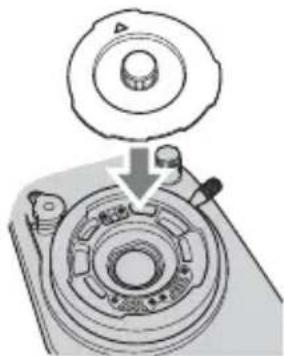
To remove the lens mount cap
Hold the protrusion at the center of the lens mount cap and remove the cap from the lens mount.
To attach the rear lens cap
Attach the rear lens cap to the rear of the lens.
To remove the rear lens cap
Hold the two protrusions on the edge of the rear lens cap as illustrated and remove the cap from the lens.

Indicators for the LCD screen and viewfinder
The numbers in ( ) are reference pages.
The indicators will not be recorded on the tape during recording.
Recording movies

1 Recording format ( er HDV1080i DVCAM, DV SP) (80)
②Remaining battery (approx.)
3 Recording status ([STBY] (standby) or [REC] (recording))
4 During recording: Tape counter (hour: minute: second: frame) During playback: Time code (hour: minute: second: frame)
5 Recording capacity of the tape (approx.)
6 Audio level display (78)
Recording still images
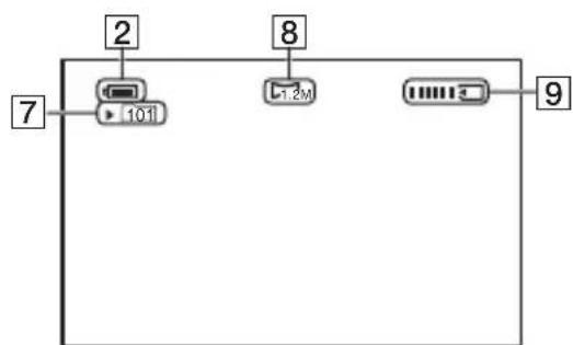
7 Recording folder (88)
8Image size (27)
9 Recording indicator (27)
Data code during recording
The date/time during recording and the camera setting data will be recorded automatically. They do not appear on the screen during recording, but you can check them on the screen by pressing the DATA CODE button during playback (p. 58).
Viewing movies

10 Tape transport indicator Recording mode (DVCAM or DV SP) appears when a tape recorded in the DVCAM or DV SP format is played back. DVCAM
Viewing still images
![graph TD A["101-001"] --> B["1.2M"] C["9/9 101"] --> D["MEMORY PLAY"] E["12"] --> F["14"] G["11"] --> H["2"] I["8"] --> J["13"]](/content/2026/07/1523711/images/80d2a7570faa7d6e9af3f0781956f9815b251a9088bd7ed63dccda71b8bb4b98.jpg)
11 Data file name
12 Picture number/Total number of recorded pictures in the current playback folder
13Playback folder (88)
14 Previous/Next folder icon
The ←, → or ↔ appears when the first or last picture of the current folder is displayed and when there are multiple folders on the same “Memory Stick Duo.” You can move to Previous/Next folder with the VOLUME/MEMORY button.
Indicators for the LCD screen and viewfinder (Continued)
Indicators when you made changes
Upper left Upper right
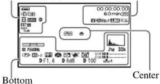
Upper left
| Indicator Meaning | |
| HDVI080i | Recording format (80) |
| DVCAM DV SP | |
| 4:3 | DV WIDE REC (82)* |
| Q.REC | QUICK REC (90)** |
| ID | DV FRAME REC (72)* |
| ND1 ND2 CLR 1/4 | ND filter (32) |
| ND3 ND4 1/16 1/64 | |
| ND | |
 | INTERVAL REC (71) |
| EXT EXT FL EXT RE CTRL (84) | |
| 24pSCAN 24P 24pSCNA 30P 30pSCAN | REC TYPE SCAN TYPE (81) |
Upper right
| Indicator Meaning | |
| INDEX MARK (49) | |
| HDVIN DVIN | HDV input/ DV input (92) |
| HDVOUT DVOUT | HDV output/ DV output (92) |
| iLINK | i.LINK connection (60, 92) |
| OFF | LCD backlight off (19) |
Center
| Indicator Meaning | ||
| Warning | (106) | |
Bottom
| Indicator Meaning | |
| HISTOGRAM (76) | |
| CAM LEVELING(78) | |
| 2CH 4CH | HDV 2CH/4CH(74)** |
| 32k AU.MODE (DVAudio mode) (74)* | |
| JM | Manual volumecontrol(45) |
| F Manual focus (30) | |
| PP1 ~ Picture profile (36) | |
| SPOTLIGHT (69) | |
| BACK LIGHT (69) | |
| SteadyShot off (69) | |
| PEAKING | PEAKING (31, 77) |
| D.EXTENDER (70) | |
| AS | AE SHIFT (68) |
| Auto setting (78) | |
| White balance (34) | |
| OFF | FOCUS MACRO(70) |
| HYPER | HYPER GAIN (67) |
| (COLOR) | x.v.Color (72)** |
| ZEBRA (76) | |
* The settings can be made only for the pictures in the DVCAM (DV) format.
**The setting can be made only for the pictures in the HDV format.
Tips
- Indicators may look different or appear at different positions.
Indicators on the sub LCD screen

1 Recording format
2 Time code/user bit
3 Tape remaining indicator
④ Battery capacity indicator
52CH/4CH audio mode
6 Audio level indicator
Index
A
A button....51
Access lamp....24
Accessory shoe.....127
Accessory shoe kit......8
Accessory shoe mount......127
ADVANCE ....77
AE RESPONSE......69
AE SHIFT......68, 99
AE SHIFT button ....48
AE WINDOW ......68
AF ASSIST....70
AGC CH1,2 ....74
AGC CH3,4 75
AGC LIMIT ......67
AGC switch ....33
ALL ERASE....87
ALL FILES....87
ALL OUTPUT ....80
ANTON/BAUER .....90
ASPECT 77
ASSIGN 4 button .....48
ASSIGN 5 button .....48
ASSIGN 6 button .....48
ASSIGN BTN......48
ASSIGN buttons......48
AT IRIS LMT......69
ATW SENS ......68
ATW switch ....34
AUDIO INPUT1 (L) jack.....45
AUDIO INPUT2 (R) jack ....45
AUDIO INPUT3 jack......45
AUDIO INPUT4 jack......45
AUDIO LEVEL DISPLAY switch....125
AUDIO MONITOR switch 47
AUDIO OUT jacks......60
AUDIO SET menu .....74
AUTO ADJUST......10
AU.LMT CH1,2 ....74
AU.LMT CH3,4....74
AU.LVL DISP
(Audio level display) ..... 78
B
B button.... 51
BACK LIGHT ...... 69, 99
BAR 78
Battery.... 15
Battery release button ..... 15
BATTERY TYPE...... 90
BEEP....90
Black balance.... 36
BLACK FADER.... 70
BLACK GAMMA...... 38
BLACK LEVEL 38
Built-in speaker.... 125
C
Cable holder.... 9
CAM DATA DSP (Camera
data display).... 78, 99
CAM LEVELING.... 78
CAMERA MODE switch .... 32
CAMERA PROF.
(Camera profile)...... 88
CAMERA SET menu ...... 67
CAMERA/VCR switch..... 17
Cassette
Ejecting.... 23
Inserting a mini-size
cassette.... 22
Tape 107
Cassette lid.... 22
CH1 dial.... 45
CH1 switch 45
CH2 dial.... 45
CH2 switch 45
CH3 dial.... 45
CH3 switch 45
CH4 dial.... 45
CH4 switch 45
CLOCK SET 20
CNTRST ENHCR ......69, 99
COLOR BAR 73
COLOR CORRCT (Color
Correct)....40
COLOR DEPTH ....40
COLOR LEVEL......39
COLOR MODE......39
COLOR PHASE......39
COMPONENT OUT jacks...60
Connect
TV 60
COPY 43
Cover 121
CURRENT FLDR 87
D
DATA CODE button......58
Date and time ......21, 128
DATE REC ......90, 99
DC IN 12V jack....60
DC OUT 12V jack......60
DEGREE 79
Deleting camera profile settings 89
Deleting recorded pictures 57
DETAIL 42
DF....85
DIGITAL EXTENDER
button....48
DISP OUTPUT ....80
DISPLAY button......19, 58
DISPLAY SET menu......76
DOWN CONV AU ....83
DOWN CONVERT......82, 83
DRUM RUN ......91
DV 80
DV AU. MODE
(DV Audio mode).... 74
DV format ....81
DV FRAME REC...... 72, 100
DV PROGRE....82
DV REC MODE
(Recording mode) 82
DV SP....82
DV WIDE CONV......83
DV WIDE REC ....82
DVCAM 82
D.EXTENDER
(Digital Extender) .....70, 99
E
End search....50
END TRIGGER....71
Expanded focus....31
EXP.FOCUS TYPE......78
EXT ONLY 84
EXT REC CTRL ......84, 100
F
FADER 70,99
FILE NO. (File number) .....87
FLANGE BACK .....73, 100
Flange focal length .....9
FLCKR REDUCE ......69
Focus....30
FOCUS DISP....79
FOCUS MACRO......70, 100
FOCUS MARKING .....72
Focus marking ....54
Focus ring ....30
FOCUS TRANS ....51
Folder
NEW FOLDER .....87
PB FOLDER (Playback folder) ....88
REC FOLDER (Recording folder) 88
FORMAT......87
FREE RUN 86
FS32K....74
FS48K....74
G
Gain....33
GAIN SETUP ......67
GAIN switch ....33
GAMMA.... 38
GL SERIES.... 90
Grip belt ....17
GUIDEFRAME 77
H
HANDLE ZOOM .....70
Handle zoom 29
Handle zoom lever 29
Handle zoom switch...... 29
HDV....81
HDV 2CH/4CH....74
HDV PROGRE. 81
HDV1080i.... 80
HDV/DV jack ....60
HDV/DV jack cover...... 121
HD/SD SDI OUT jack ..... 60
HISTOGRAM....76, 99
HOURS METER.... 91
HYPER GAIN....67
|
INDEX MARK ......49
Index screen 56
Index signal.... 49
Indicators.... 130
INDOOR 35
Indoor.... 35
INPUT1 MIC NR.... 75
INPUT1 switch .....45
INPUT1 TRIM.... 75
INPUT1 WIND......75
INPUT2 MIC NR.... 75
INPUT2 switch .....45
INPUT2 TRIM.... 75
INPUT2 WIND....75
INPUT3 MIC NR .....75
INPUT3 switch......45
INPUT3 TRIM .....75
INPUT3 WIND .....75
INPUT4 MIC NR .....75
INPUT4 switch......45
INPUT4 TRIM 75
INPUT4 WIND .....75
INTELLIGENT ......68
INTERLACE....81
INTERVAL ....71
INTERVAL REC .....71, 99
IN/OUT REC menu......80
Iris ring 32
IRIS switch 32
IRIS TRANS ....51
i.LINK 111
i.LINK cable ......92, 94
i.LINK Cradle....14
i.LINK SET 83
J
JPEG....110
K
KNEE 39
L
L SERIES 90
L1 button ....48
L2 button 48
LANC jack....126
LANGUAGE......89
Last scene review ....50
LAST SCN RVW....50
LCD BACK LIGHT switch 125
LCD BL LEVEL .....79
-LCD BRIGHT+ buttons.....19
LCD COLOR....79
Lens 9
Index (Continued)
Lens cover lever ......12
Lens hood with lens cover....11
LENS jack 9
Lens mount....9
Lens mount cap ......127
Lens mount securing tab......9
LETTER SIZE......79
LIGHT connector ......121
LIGHT MAN/AUTO switch 123
LIGHT ON/OFF switch .....122
M
MANU ADJUST......10
MANU WB TEMP......68
MARKER....77, 100
Memory A ....35
Memory B....35
Memory Recording Unit .....13
MEMORY SET menu......87
Memory Stick......2
"Memory Stick"....110
"Memory Stick Duo"
Insert/Eject ......23
Number of recordable pictures ....27
Write-protect tab .....110
Memory Stick Duo slot .....23
MEMORY -/+ button .....56
MEMORY/DELETE button 57
MEMORY/INDEX button ...55
MEMORY/PLAY button .....55
Menu
AUDIO SET menu......74
CAMERA SET menu....67
DISPLAY SET menu....76
IN/OUT REC menu.....80
MEMORY SET menu 87
Menu items......64
OTHERS menu .....88
TC/UB SET menu ..... 85
Using the menu...... 62
Menu items 64
MENU/STATUS switch ..... 62
Microphone.... 11
Microphone fixing clamper 11
Microphone holder...... 11
Mode A 30
Mode B 30
Moisture condensation ..... 113
MONITOR dial.... 56
MONITOR SELECT button 47
MPEG2 96
N
ND filter.... 32
NDF 85
NEW FOLDER.... 87
NTSC 103
NUMBER 78
0
ONE PUSH AF...... 31
One push auto focus...... 31
One push button.... 35
OPERATION...... 91
OTHERS menu.... 88
Outdoor 35
OUTPUT/DCC switch..... 123
P
PB FOLDER
(Playback folder)...... 88
PB ZOOM (Playback zoom)
90
PEAKING.... 77, 99
PEAKING switch 18
PHONES jack 125
Picture profile 36
PICTURE PROFILE button
36
Picture Search......56
PLAY button ....55
POWER switch ....17
Pre-installed rechargeable battery....115
PRESET 85
PROFILE NAME......43
PROGRESSIVE......81
PUSH AUTO button ......32
PUSH (lens hood release) button....11
Q
QUICK REC ....90
R
Rear lens cap ......127
REC CH SELECT switch 11
REC CTL MODE......84
REC FOLDER (Recording folder) 88
REC FORMAT ....80
REC LAMP[R]......90
REC LINK....51
REC PAUSE 84
Rec review....50
REC REVIEW button .....50
REC RUN....85
REC START/STOP button 25
REC TIME ....71
REC TIMING......71
REC TYPE 81
Rechargeable battery pack ...15
Recording 25
Recording lamp 25
REGENERATE......86
RELAY....84
RELEASE button 115
REMAINING......80
RESET......43, 85
RESET button....125
RET button ....48
s
S VIDEO jack......60
SAFETY ZONE ....77
SCAN TYPE......81
SDI OUTPUT 82
SDI/CMPNT......82
SD-SDI SET 83
Self-diagnosis display......106
SEL/PUSH EXEC dial .....20
SHOT TRANSITION......72
Shot transition......51
SHOT TRANSITION/FOCUS
MARKING button......51
SHUTTER DISP....79
Shutter speed....33
SHUTTER switch....33
SKINTONE DTL (Skintone detail) 43
Skip Scan 56
SMOOTH GAIN ......67
SMOOTH WB......68
SMTH SLW REC
(Smooth slow recording) 71, 100
Specifications......117
SPOTLIGHT ......69, 99
START TIMER 51
START TRIGGR....71
Status check ....59
STBY COMMAND......84
STEADYSHOT ......69, 100
STEADYSHOT button......48
STOP 84
Sub LCD panel .....131
Supplied items 8
SYNCHRONOUS ....84
S.TRANS/F.MARK......72
T
TALLY switch ......122
Tape counter...... 128
TAPE RUN 91
TC COUNTUP...... 85, 100
TC FORMAT.... 85
TC LINK 86,100
TC MAKE.... 86
TC OUT jack....121
TC PRESET 85
TC RUN 85
TC/UB SET menu 85
TC/U-BIT button.... 125
Telephoto 29
Test chart.... 9
THREADING 91
Time code....128
TONE....73
Trademark 120
TRANS TIME....51
Troubleshooting 97
TV 60
U
UB PRESET...... 85
UB TIME REC...... 86
UB-DATE/TC-TIME... 86, 100
Using the menu items...... 62
V
VCR HDV/DV 80
VF B.LIGHT....79
VF COLOR 79
Video control buttons...... 55
Video head 114
VIDEO OUT 82
VIDEO OUT jack 60
VIDEO OUT switch...... 60
Viewfinder front-to-back position fixing ring .... 18
Viewfinder left-to-right position fixing ring ....18
Viewfinder lens adjustment lever ....18
Volume 56
V-OUT/PANEL......80
W
Warning indicators .....106
Warning messages ......106
WB OUTDR LVL ......67
WB PRESET ......67
WB SHIFT......42
WB TEMP SET......68
White balance ....34
White balance memory switch 35
WHITE FADER ....70
WHT BAL switch....34
WHT/BLK switch ....34
Wide angle....29
Wind screen ....11
WORLD TIME......89, 100
Write-protect tab......108, 110
X
XLR SET....74
x.v.Color ....72, 100
Z
ZEBRA....76, 99
ZEBRA button....48
Zoom....29
ZOOM DISPLAY .....78
Zoom lever....29
Zoom ring 29
ZOOM switch....29
ZOOM TRANS ....51
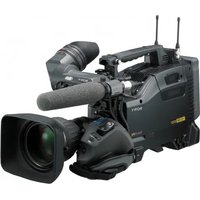
- READ THIS FIRST
- NOTES ON USE
- TYPES OF CASSETTE YOU CAN USE IN YOUR CAMCORDER
- THE HDV FORMAT
- TYPES OF "MEMORY STICK" YOU CAN USE IN YOUR CAMCORDER
- NOTES
- USING THE CAMCORDER
- ABOUT MENU ITEMS, LCD PANEL, VIEWFINDER, AND LENS
- DO NOT EXPOSE YOUR CAMCORDER'S VIEWFINDER, LENS, OR LCD SCREEN TO THE SUN OR STRONG LIGHT SOURCE FOR EXTENDED PERIODS
- ON RECORDING
- READ THIS FIRST (CONTINUED)
- ON PLAYING BACK HDV TAPES ON OTHER DEVICES
- NOTES ON THE ICONS USED IN THIS MANUAL
- ABOUT THIS MANUAL
- ABOUT THE CARL ZEISS LENS
- TABLE OF CONTENTS
- GETTING STARTED
- RECORDING/PLAYBACK
- USING THE MENU
- DUBBING/EDITING
- TROUBLESHOOTING
- ADDITIONAL INFORMATION
- MAINTENANCE AND PRECAUTIONS
- SPECIFICATIONS
- QUICK REFERENCE
- STEP 1: CHECKING SUPPLIED ITEMS
- STEP 2: ATTACHING THE SUPPLIED ITEMS
- MOUNTING THE LENS
- MOUNTING THE CARL ZEISS LENS
- MOUNTING NON-CARL ZEISS LENS
- TIPS
- ADJUSTING THE FLANGE FOCAL LENGTH (FOR CARL ZEISS LENS)
- STEP 2: ATTACHING THE SUPPLIED ITEMS (CONTINUED)
- ADJUSTING THE FLANGE FOCAL LENGTH AUTOMATICALLY
- ADJUSTING THE FLANGE FOCAL LENGTH MANUALLY
- ATTACHING THE SUPPLIED MICROPHONE
- ATTACHING THE LENS HOOD WITH LENS COVER
- TO REMOVE THE LENS HOOD WITH LENS COVER
- TO OPEN OR CLOSE THE SHUTTER OF THE LENS HOOD WITH LENS COVER
- ATTACHING THE SHOULDER STRAP
- FIT ONE OF THE CLIPS TO A SHOULDER STRAP FITTING
- TO REMOVE THE SHOULDER STRAP
- ATTACHING MEMORY RECORDING UNIT
- TO REMOVE THE MEMORY RECORDING UNIT
- TO ATTACH THE MEMORY RECORDING UNIT TO THE I.LINK CRADLE
- TO REMOVE THE MEMORY RECORDING UNIT FROM THE I.LINK CRADLE
- STEP 3: PREPARING A POWER SUPPLY
- USING A BATTERY PACK
- TO ATTACH THE BATTERY PACK
- TO DETACH THE BATTERY PACK
- STEP 3: PREPARING A POWER SUPPLY (CONTINUED)
- USING AN AC ADAPTOR
- TO USE THE AC-550 AC ADAPTOR
- TO USE THE AC-DN10 AC ADAPTOR
- AVOIDING BREAKS IN OPERATION DUE TO AN EXHAUSTED BATTERY
- STEP 4: TURNING THE POWER ON AND HOLDING YOUR CAMCORDER PROPERLY
- TO TURN OFF THE POWER
- STEP 5: ADJUSTING THE VIEWFINDER AND LCD PANEL
- THE VIEWFINDER
- TO ATTACH THE LARGE EYECUP
- TO ADJUST THE VIEWFINDER POSITION
- TO ADJUST THE EYEPIECE FOCUS
- TO ADJUST THE IMAGE DETAIL
- TO ADJUST THE BRIGHTNESS
- THE LCD PANEL
- STEP 6: SETTING THE DATE AND TIME
- PUSH THE MENU/STATUS SWITCH TO MENU
- SELECT (OTHERS) BY TURNING THE SEL/PUSH EXEC DIAL, THEN PRESS THE DIAL
- SELECT [CLOCK SET] BY TURNING THE SEL/PUSH EXEC DIAL, THEN PRESS THE DIAL
- SET [Y] (YEAR) BY TURNING THE SEL/PUSH EXEC DIAL, THEN PRESS THE DIAL
- SET [M] (MONTH), [D] (DAY), HOUR AND MINUTE, THEN PRESS THE DIAL
- CHANGING THE LANGUAGE SETTING
- STEP 7: INSERTING A TAPE OR A “MEMORY STICK DUO
- CASSETTE TAPE
- TO INSERT A MINI-SIZE CASSETTE
- CLOSE THE CASSETTE LID UNTIL IT CLICKS
- TO EJECT A CASSETTE
- MEMORY STICK DUO
- OPEN THE AUDIO CONTROL PANEL COVER
- INSERT THE "MEMORY STICK DUO" INTO THE MEMORY STICK DUO SLOT IN THE RIGHT DIRECTION UNTIL IT CLICKS
- TO EJECT A "MEMORY STICK DUO
- OPEN THE SHUTTER OF THE LENS HOOD
- SET THE POWER SWITCH TO ON AND THE CAMERA/VCR SWITCH TO CAMERA
- PRESS THE REC START/STOP BUTTON A (OR B, C)
- TO USE THE VIDEO LIGHT
- TO CAPTURE STILL IMAGES
- CAPACITY OF THE “MEMORY STICK DUO” (MB) AND THE NUMBER OF RECORDABLE PICTURES
- TO STORE STILL IMAGES CAPTURED FROM MOVIES ON A TAPE ON “MEMORY STICK DUO
- RECORDING (CONTINUED)
- CHANGING THE SETTINGS OF YOUR CAMCORDER RECORDINGS
- ADJUSTING THE ZOOM
- USING THE ZOOM LEVER
- USING THE HANDLE ZOOM
- USING THE ZOOM RING
- CHANGING THE SETTINGS OF YOUR CAMCORDER RECORDINGS (CONTINUED)
- ADJUSTING THE FOCUS MANUALLY
- ADJUSTING FOCUS MANUALLY IN MODE A
- ADJUSTING FOCUS MANUALLY IN MODE B
- TO RESTORE AUTOMATIC ADJUSTMENT
- USING AUTOMATIC FOCUS TEMPORARILY (ONE PUSH AUTO FOCUS)
- USING THE EXPANDED FOCUS (EXPANDED FOCUS)
- FOCUSING ON A DISTANT SUBJECT (FOCUS INFINITY)
- ENHANCING IMAGE DETAIL FOR FOCUSING (PEAKING)
- ADJUSTING THE IRIS
- TO ADJUST THE IRIS AUTOMATICALLY
- ADJUSTING THE VOLUME OF LIGHT (ND FILTER)
- ADJUSTING THE GAIN
- TO ADJUST THE GAIN AUTOMATICALLY
- ADJUSTING THE SHUTTER SPEED
- TO ADJUST THE SHUTTER SPEED AUTOMATICALLY
- ADJUSTING TO NATURAL COLOR (WHITE BALANCE)
- SET THE WHT BAL SWITCH D TO ANY ONE OF PRST/A/B
- TO SAVE THE ADJUSTED WHITE BALANCE VALUE IN MEMORY A OR B
- TO ADJUST THE WHITE BALANCE AUTOMATICALLY
- ADJUSTING THE BLACK BALANCE
- IF THE BLACK BALANCE ADJUSTMENT FAILS
- CUSTOMIZING THE PICTURE QUALITY (PICTURE PROFILE)
- DURING STANDBY, PRESS THE PICTURE PROFILE BUTTON B
- SELECT A PICTURE PROFILE NUMBER WITH THE SEL/PUSH EXEC DIAL A
- SELECT [OK] WITH THE SEL/PUSH EXEC DIAL A
- TO CANCEL THE PICTURE PROFILE RECORDING
- TO CHANGE THE PICTURE PROFILE
- BLACK LEVEL
- GAMMA
- BLACK GAMMA
- KNEE
- ITEM DESCRIPTION AND SETTINGS
- COLOR MODE
- COLOR LEVEL
- COLOR PHASE
- COLOR DEPTH
- COLOR CORRCT
- COLOR CORRCT (CONTINUED)
- WB SHIFT
- DETAIL
- SKINTONE DTL
- PROFILE NAME
- COPY
- RESET
- TO NAME THE PICTURE PROFILE SETTINGS
- TO COPY THE PICTURE PROFILE SETTING TO OTHER PICTURE PROFILES
- TO RESET THE PICTURE PROFILE SETTINGS
- ADJUSTING THE VOLUME
- CH/FS48K RECORDING
- EXAMPLE OF 2CH RECORDING (RECORDING AUDIO INPUT FROM INPUT1 AND INPUT4)
- CH/FS32K RECORDING
- MONITOR THE RECORDING SOUND
- ASSIGNING THE FUNCTIONS TO THE ASSIGN BUTTONS
- FUNCTIONS YOU CAN ASSIGN TO THE ASSIGN BUTTONS
- RECORDING AN INDEX SIGNAL
- TO CANCEL THE OPERATION
- ASSIGNING THE FUNCTIONS TO THE ASSIGN BUTTONS (CONTINUED)
- REVIEWING THE MOST RECENTLY RECORDED SCENES (REC REVIEW)
- PRESS THE REC REVIEW BUTTON OR THE ASSIGN BUTTON TO WHICH [REC REVIEW] IS ASSIGNED DURING STANDBY
- SEARCHING FOR THE LAST SCENE OF THE MOST RECENT RECORDING (END SEARCH)
- ASSIGN [END SEARCH] TO ONE OF THE ASSIGN BUTTONS (P. 48)
- PRESS THE ASSIGN BUTTON TO WHICH [END SEARCH] IS ASSIGNED
- PLAYING BACK THE MOST RECENTLY RECORDED MOVIES (LAST SCENE REVIEW)
- ASSIGN [LAST SCN RVW] TO AN ASSIGN BUTTON (P. 48)
- DURING STANDBY, PRESS THE ASSIGN BUTTON TO WHICH [LAST SCN RVW] IS ASSIGNED
- USING THE SHOT TRANSITION
- MARKING FOCAL POINT ON THE SCREEN (FOCUS MARKING)
- PLAYBACK
- SET THE POWER SWITCH TO ON AND THE CAMERA/VCR SWITCH TO VCR
- START PLAYING BACK
- TO SEARCH FOR A SCENE WHILE VIEWING A MOVIE
- TO ADJUST THE VOLUME
- TO VIEW STILL IMAGES
- TO DISPLAY THE LIST OF STILL IMAGES (INDEX SCREEN)
- TO DELETE STILL IMAGES FROM THE "MEMORY STICK DUO
- CHANGING/CHECKING THE SETTINGS IN YOUR CAMCORDER
- CHANGING THE SCREEN
- PRESS THE DISPLAY BUTTON A
- DISPLAYING RECORDING DATA (DATA CODE)
- SET THE CAMERA/VCR SWITCH E TO VCR
- PRESS THE DATA CODE BUTTON B DURING PLAYBACK OR PAUSE
- DISPLAYING THE SETTINGS IN YOUR CAMCORDER (STATUS CHECK)
- TO HIDE THE DISPLAY
- CONNECTING A MONITOR OR A TV
- USING THE MENU ITEMS
- MENU
- GAIN SETUP
- SMOOTH GAIN
- HYPER GAIN
- AS
- AGC LIMIT
- WB PRESET
- WB OUTDR LVL
- WB TEMP SET
- ATW SENS
- INTELLIGENT
- HIGH
- MIDDLE
- LOW
- SMOOTH WB
- AE SHIFT AS
- AE WINDOW
- AE RESPONSE
- AT IRIS LMT
- FLCKR REDUCE
- ON
- OFF
- CNTRST ENHCR
- BACK LIGHT AS
- SPOTLIGHT AS
- STEADYSHOT AS
- ON/OFF
- TYPE
- HARD
- STANDARD
- SOFT
- AF ASSIST
- FOCUS MACRO AS
- HANDLE ZOOM
- D.EXTENDER AS
- FADER AS
- STBY REC
- WHITE FADER
- BLACK FADER
- SMTH SLW REC
- INTERVAL REC
- DV FRAME REC
- ON ( )
- SHOT TRANSITION
- S.TRANS/F.MARK
- FOCUS MARKING
- X.V.COLOR HDV1080I
- COLOR BAR AS
- TONE
- FLANGE BACK
- AUTO ADJUST
- MANU ADJUST
- (AUDIO SET) MENU
- SEE PAGE 62 FOR DETAILS ON SELECTING MENU ITEMS
- HDV 2CH/4CH
- HDV1080I
- CH
- DV AU.MODE
- FS48K (48K
- AU.LMT CH
- XLR SET
- AGC CH
- SEPARATE
- LINKED
- INPUT1 MIC NR
- INPUT1 TRIM
- INPUT1 WIND
- INPUT2 MIC NR
- INPUT2 TRIM
- INPUT2 WIND
- INPUT3 MIC NR
- INPUT3 TRIM
- INPUT3 WIND
- INPUT4 MIC NR
- INPUT4 TRIM
- INPUT4 WIND
- (DISPLAY SET)
- ZEBRA AS
- LEVEL
- HISTOGRAM
- NORMAL
- ADVANCE
- PEAKING
- MARKER
- CENTER
- ASPECT
- SAFETY ZONE
- GUIDEFRAME
- CAM LEVELING
- EXP.FOCUS TYPE
- CAM DATA DSP (CAMERA DATA DISPLAY)
- AU.LVL DISP (AUDIO LEVEL DISPLAY)
- ZOOM DISPLAY
- BAR
- NUMBER
- FOCUS DISP
- METER
- FEET
- SHUTTER DISP
- SECOND
- DEGREE
- LCD COLOR
- LCD BL LEVEL
- BRIGHT
- VF B. LIGHT
- VF COLOR
- LETTER SIZE
- ×
- REMAINING
- AUTO
- DISP OUTPUT
- LCD PANEL
- V-OUT/PANEL
- ALL OUTPUT
- (IN/OUT REC)
- REC FORMAT
- VCR HDV/DV
- HDV (HDV1080I
- DV (DV)
- HDV PROGRE. HDV1080I
- REC TYPE
- SCAN TYPE
- A
- DV PROGRE. DVCAM DV SE
- DV REC MODE (DV RECORDING MODE) DVCAM DV 亚
- DV WIDE REC DVCAM DV SE
- OFF (4:3)
- SDI OUTPUT
- VIDEO OUT
- SDI/CMPNT
- I
- I/480I
- DOWN CONVERT
- SQUEEZE
- LETTER BOX
- EDGE CROP
- DV WIDE CONV
- SD-SDI SET
- VIDEO INDEX
- RP188 ATC
- VITC LINESEL
- I.LINK SET
- HDV → DV CONV
- DOWN CONV AU
- CH1,CH
- CH3, CH
- EXT REC CTRL
- REC CTL MODE
- SYNCHRONOUS (EXT)
- RELAY (EXT)
- EXT ONLY (EXT)
- STBY COMMAND
- REC PAUSE
- STOP
- (TC PRESET/UB PRESET/TC LINK, ETC.)
- TC PRESET
- PRESET
- TC COUNTUP AS
- UB PRESET
- TC FORMAT
- DF
- NDF
- TC RUN
- REC RUN
- FREE RUN
- TC MAKE
- REGENERATE
- TC LINK
- UB TIME REC
- UB-DATE/TC-TIME
- (MEMORY SET)
- ALL ERASE
- FORMAT
- FILE NO
- SERIES
- NEW FOLDER
- REC FOLDER (RECORDING FOLDER)
- PB FOLDER (PLAYBACK FOLDER)
- (OTHERS) MENU
- CAMERA PROF. (CAMERA PROFILE)
- TO LOAD A CAMERA PROFILE
- TO SAVE A CAMERA PROFILE
- TO CHANGE THE CAMERA PROFILE NAME
- TO DELETE CAMERA PROFILE SETTINGS
- TO COPY A CAMERA PROFILE
- ASSIGN BTN
- CLOCK SET
- WORLD TIME
- LANGUAGE
- PB ZOOM (PLAYBACK ZOOM)
- QUICK REC HDV1080I
- ON (Q.REC
- DATE REC
- BEEP
- REC LAMP[R] (RECORDING LAMP [REAR]) AS
- BATTERY TYPE
- L SERIES
- GL SERIES
- ANTON/BAUER
- HOURS METER
- OPERATION
- DRUM RUN
- TAPE RUN
- THREADING
- RECORDING PICTURES FROM A VCR I.LINK
- RECORDING MOVIES
- SET THE CAMERA/VCR SWITCH TO VCR
- SET THE INPUT SIGNAL OF YOUR CAMCORDER
- CONNECT YOUR VCR AS A PLAYER TO YOUR CAMCORDER
- INSERT A CASSETTE INTO THE VCR
- SET YOUR CAMCORDER TO RECORDING PAUSE
- START PLAYING THE CASSETTE ON YOUR VCR
- PRESS II (PAUSE) AGAIN AT THE POINT YOU WANT TO START RECORDING
- PRESS ■ (STOP) TO STOP RECORDING
- RECORDING STILL IMAGES
- PERFORM STEPS 1 TO 4 IN "RECORDING MOVIES
- RECORDING PICTURES FROM A VCR (CONTINUED)
- START PLAYING THE CASSETTE
- PRESS THE ASSIGN BUTTON TO WHICH [PHOTO] IS ASSIGNED AT THE SCENE YOU WANT TO RECORD
- COPYING MOVIES ON A TAPE TO A COMPUTER
- NOTES ON CONNECTING TO THE COMPUTER
- STEP:2 COPYING THE MOVIES
- WHEN COPYING THE MOVIE IN THE HDV FORMAT FROM THE COMPUTER TO YOUR CAMCORDER
- WHEN COPYING THE MOVIE IN THE DVCAM (DV) FORMAT FROM THE COMPUTER TO YOUR CAMCORDER
- POWER SOURCES/LCD SCREEN
- THE POWER DOES NOT TURN ON OR ABRUPTLY TURNS OFF
- THE CAMCORDER DOES NOT OPERATE EVEN WHEN THE POWER IS SET TO ON
- THE CAMCORDER GETS WARM
- THE REMAINING BATTERY TIME INDICATOR DOES NOT INDICATE THE CORRECT TIME
- THE BATTERY PACK DISCHARGES TOO QUICKLY
- THE PICTURE REMAINS ON THE LCD SCREEN
- THE PICTURE IN THE VIEWFINDER IS NOT CLEAR
- CASSETTE TAPES/“MEMORY STICK DUO
- THE CASSETTE CANNOT BE EJECTED FROM THE COMPARTMENT
- THE CASSETTE MEMORY INDICATOR OR TITLE DISPLAY DOES NOT APPEAR WHILE USING A CASSETTE WITH CASSETTE MEMORY
- THE REMAINING TAPE INDICATOR IS NOT DISPLAYED
- YOU CANNOT DELETE PICTURES OR FORMAT THE "MEMORY STICK DUO
- RECORDING
- THE RECORDING DOES NOT START WHEN YOU PRESS THE REC START/STOP BUTTON
- THE HANDLE ZOOM DOES NOT WORK
- YOU CANNOT RECORD ON THE "MEMORY STICK DUO
- YOU CANNOT RECORD A SMOOTH TRANSITION ON A TAPE FROM THE LAST RECORDED SCENE TO THE NEXT
- THE SHUTTER SOUND IS NOT HEARD WHEN YOU RECORD A STILL IMAGE
- END SEARCH OR LAST SCENE REVIEW DOES NOT WORK
- AUTO FOCUS DOES NOT FUNCTION
- MENU ITEMS ARE GRAYED OUT OR DO NOT WORK
- THE SUBJECTS PASSING BY THE FRAME VERY FAST APPEAR CROOKED
- THE SCREEN PICTURE IS BRIGHT, AND THE SUBJECT DOES NOT APPEAR ON THE SCREEN
- THE SCREEN PICTURE IS DARK, AND THE SUBJECT DOES NOT APPEAR ON THE SCREEN
- HORIZONTAL STRIPES APPEAR ON THE IMAGE
- BLACK BANDS APPEAR WHEN YOU RECORD A TV SCREEN OR COMPUTER SCREEN
- THE BEGINNING OF THE RECORDING LOOKS DARK WHEN THE VIDEO LIGHT COMES ON LINKED TO THE START OF MOVIE RECORDING (WHEN THE LIGHT MAN/AUTO SWITCH IS SET TO AUTO)
- THE VIDEO LIGHT DOES NOT COME ON
- FINE PATTERNS FLICKER, DIAGONAL LINES LOOK JAGGED
- YOU CANNOT PLAY BACK TAPE
- IMAGE DATA STORED ON A “MEMORY STICK DUO” CANNOT BE PLAYED BACK CORRECTLY
- THE DATA FILE NAME IS DISPLAYED INCORRECTLY, OR FLASHING
- HORIZONTAL LINES APPEAR ON THE PICTURE. THE DISPLAYED PICTURES ARE NOT CLEAR OR DO NOT APPEAR
- YOU CANNOT HEAR THE SOUND RECORDED WITH 4CH MICROPHONE RECORDING ON YOUR CAMCORDER
- NO SOUND OR ONLY A LOW SOUND IS HEARD
- THE PICTURE OR SOUND BREAKS OFF
- THE MOVIES FREEZE FOR A WHILE, OR THE SOUND BREAKS OFF
- IS DISPLAYED ON THE SCREEN
- NOISES APPEAR AND POR IS DISPLAYED ON THE SCREEN
- DATE SEARCH DOES NOT WORK CORRECTLY
- NO PICTURE APPEARS DURING END SEARCH, REC REVIEW OR LAST SCENE REVIEW
- ST APPEARS ON THE LCD SCREEN
- CONNECTING TO TV
- YOU CANNOT VIEW THE PICTURE ON THE TV CONNECTED WITH THE I.LINK CABLE
- YOU CANNOT HEAR THE SOUND ON THE TV CONNECTED WITH THE S VIDEO PLUG (S VIDEO CHANNEL) OR COMPONENT VIDEO PLUG
- DUBBING/EDITING/CONNECTING TO OTHER DEVICES
- CONNECTING TO A COMPUTER
- YOU CANNOT VIEW OR COPY A MOVIE RECORDED ON A TAPE TO A COMPUTER. I.LINK
- YOUR COMPUTER FREEZES
- WARNING INDICATORS AND MESSAGES
- SELF-DIAGNOSIS DISPLAY/WARNING INDICATORS
- C:(OR E:) □□:□□ (SELF-DIAGNOSIS DISPLAY)
- C
- C:31:□□ / C
- E:61:□□ / E
- (WARNING INDICATOR PERTAINING TO FILES)
- (BATTERY LEVEL WARNING)
- (MOISTURE CONDENSATION WARNING)
- WARNING INDICATORS PERTAINING TO THE TAPE)
- SLOW FLASHING
- FAST FLASHING
- ▲ (EJECT CASSETTE WARNING)
- WARNING MESSAGES
- HDV FORMAT AND RECORDING/ PLAYBACK
- WHAT IS THE HDV FORMAT
- TO PREVENT A BLANK SECTION FROM BEING CREATED ON THE TAPE
- COPYRIGHT SIGNAL
- WHEN YOU PLAY BACK
- WHEN YOU RECORD
- AUDIO MODE
- FS32K (12-BIT) MODE
- FS48K (16-BIT) MODE
- WHEN NOT USING YOUR CAMCORDER FOR A LONG TIME
- MAINTENANCE AND PRECAUTIONS (CONTINUED)
- TO PREVENT ACCIDENTAL ERASURE
- WHEN LABELING THE CASSETTE
- AFTER USING THE CASSETTE
- WHEN CLEANING THE GOLD-PLATED CONNECTOR
- ON SONY HDV1080I COMPLIANT TVS
- COMPATIBILITY OF THE DVCAM/DV FORMATS
- DIFFERENCES BETWEEN THE DVCAM AND DV FORMATS
- COMPATIBILITY ON EDITING USING DV JACKS
- LIMITATIONS ON EDITING
- I (I.LINK) JACK
- ABOUT THE "MEMORY STICK
- ON THE MEMORY STICK DUO ADAPTOR
- ON A "MEMORY STICK PRO DUO
- NOTES ON USING "MEMORY STICK MICRO
- ON IMAGE DATA COMPATIBILITY
- ABOUT STORAGE OF THE BATTERY PACK
- ABOUT BATTERY LIFE
- ABOUT I.LINK
- WHAT IS I.LINK
- ABOUT THE I.LINK BAUD RATE
- WHAT IS MBPS
- TO USE I.LINK FUNCTIONS ON THIS UNIT
- ABOUT X.V.COLOR
- ABOUT HANDLING OF YOUR CAMCORDER
- ON USE AND CARE
- MOISTURE CONDENSATION
- IF MOISTURE CONDENSATION HAS OCCURRED
- ON HANDLING THE CASING
- ABOUT CARE AND STORAGE OF THE LENS
- ON CHARGING THE PRE-INSTALLED RECHARGEABLE BATTERY
- PROCEDURES
- REMOVING DUST FROM INSIDE THE VIEWFINDER
- REMOVE THE EYE PIECE OF THE VIEWFINDER
- REMOVE DUST INSIDE THE EYE PIECE AND VIEWFINDER WITH A BLOWER
- SYSTEM
- SPECIFICATIONS (CONTINUED)
- LENS
- FOCAL LENGTH
- COLOR TEMPERATURE
- MINIMUM ILLUMINATION
- OUTPUT CONNECTORS
- VIDEO OUT JACK
- SVIDEO JACK
- AUDIO OUT JACK
- TC OUT JACK
- COMPONENT OUT JACK
- HD/SD SDI OUT JACK
- INPUT/OUTPUT CONNECTORS
- LANC JACK
- AUDIO INPUT1 (L)/AUDIO INPUT
- (R)/AUDIO INPUT3/AUDIO INPUT
- JACK
- PHONES JACK
- DC OUT 12V CONNECTOR
- LIGHT CONNECTOR
- LENS JACK
- I HDV/DV JACK
- DC IN 12V CONNECTOR
- LCD SCREEN
- PICTURE
- TOTAL DOT NUMBER
- GENERAL
- POWER REQUIREMENTS
- AVERAGE POWER CONSUMPTION
- OPERATING TEMPERATURE
- STORAGE TEMPERATURE
- DIMENSIONS (APPROX.)
- MASS (APPROX.)
- ON TRADEMARKS
- NOTES ON THE LICENSE
- IDENTIFYING PARTS AND CONTROLS
- IDENTIFYING PARTS AND CONTROLS (CONTINUED)
- OUTPUT: CAM, DCC: ON
- OUTPUT: BARS, DCC: OFF
- TO MOUNT THE ACCESSORY SHOE
- TO DISMOUNT THE ACCESSORY SHOE
- TO ATTACH THE LENS MOUNT CAP
- TO REMOVE THE LENS MOUNT CAP
- TO ATTACH THE REAR LENS CAP
- TO REMOVE THE REAR LENS CAP
- INDICATORS FOR THE LCD SCREEN AND VIEWFINDER
- DATA CODE DURING RECORDING
- VIEWING MOVIES
- VIEWING STILL IMAGES
- INDICATORS FOR THE LCD SCREEN AND VIEWFINDER (CONTINUED)
- INDICATORS WHEN YOU MADE CHANGES
- INDICATORS ON THE SUB LCD SCREEN
- INDEX
- B
- D
- E
- F
- G
- H
- J
- K
- L
- INDEX (CONTINUED)
- M
- N
- P
- Q
- R
- S
- T
- U
- V
- W
- X
- Z
Brand : SONY
Model : HVR-S270N
Category : Camcorder