
505 - Guitar Multi-Effects ZOOM - Free user manual and instructions
Find the device manual for free 505 ZOOM in PDF.

| Product Type | Multi-effects for guitar |
| Brand | ZOOM |
| Model | 505 |
| Number of Built-in Effects | 24 types (compressor, limiter, auto-wah, pedal wah, overdrive, distortion, fuzz, chorus, flanger, delay, reverb, etc.) |
| Maximum Simultaneous Effects | 9 |
| Patch Memory | 24 programmable patches |
| Power Supply | 9V DC 300 mA AC adapter (ZOOM AD-0006) or 9V alkaline battery (6LR61) |
| Battery Life | Approximately 4 hours |
| Weight | 480 g |
| Input | Mono guitar jack (standard) – impedance 470 kΩ, nominal level -20 dBm |
| Output | Stereo jack (headphone/amp) – max level +6 dBm, load impedance ≥ 10 kΩ |
| Control Input | For FP01 expression pedal or FS01 footswitch |
| Tuner | Automatic chromatic, calibration range 435-445 Hz |
| Effect Modules | COMP, DIST, ZNR/AMP, EQ, MOD, DLY/REV, PATCH LEVEL |
| Special Functions | Bypass/Mute, Direct Load, Bank Hold, Master Level |
| Cleaning | Soft dry cloth, do not use solvents |
| Optional Accessories | FP01 expression pedal, FS01 footswitch, AD-0006 adapter |
| Safety | Use only specified adapter; do not open the casing; protect from moisture and shocks |
Frequently Asked Questions - 505 ZOOM
User questions about 505 ZOOM
0 question about this device. Answer the ones you know or ask your own.
Ask a new question about this device
Download the instructions for your Guitar Multi-Effects in PDF format for free! Find your manual 505 - ZOOM and take your electronic device back in hand. On this page are published all the documents necessary for the use of your device. 505 by ZOOM.
USER MANUAL 505 ZOOM
Thank you for selecting the ZOOM 505 (hereafter simply called the "505").
Please take the time to read this manual carefully so as to get the most out of your 505 and to ensure optimum performance and reliability. Retain this manual for future reference.
ZOOM CORPORATION
NOAH Bldg., 2-10-2, Miyanishi-cho, Fuchu-shi, Tokyo 183, Japan
PHONE: 0423-69-7111 FAX: 0423-69-7115
Printed in Japan 505-5000

1 Major Features
- 24 individual built-in effects provide maximum flexibility. Up to 9 effects can be used simultaneously in any combination.
- Memory capacity for up to 24 user-programmable patches.
- Integrated auto-chromatic guitar tuner for simple and precise tuning anywhere.
- Optional foot controller FP01 can be used for pedal wah or pedal pitch, and volume control is also possible.
- Optional foot switch FS01 can be used for bank switching, resulting in enhanced playability.
- Dual power supply principle allows the unit to be powered from an alkaline battery or an AC adapter.
- New DSP (digital signal processor) ZFx-2 developed by Zoom produces high-quality effects from an amazingly compact package.
2 Safety Precautions
USAGE AND SAFETY PRECAUTIONS
In this manual, symbols are used to highlight warnings and cautions for you to read so that accidents can be prevented. The meanings of these symbols are as follows:

Warning

Caution
This symbol indicates explanations about extremely dangerous matters. If users ignore this symbol and handle the device the wrong way, serious injury or death could result.
This symbol indicates explanations about dangerous matters. If users ignore this symbol and handle the device the wrong way, bodily injury and damage to the equipment could result.
Please observe the following safety tips and precautions to ensure hazard-free use of the 505.

Varning.
About power
Since power consumption of this unit is fairly high, we recommend the use of an AC adapter whenever possible. When powering the unit from a battery, use only an alkaline type.
AC adapter operation
- Be sure to use only an AC adapter which supplies 9 V DC, 300mA and is equipped with a "center minus" plug (Zoom AD-0006). The use of an adapter other than the specified type may damage the unit and pose a safety hazard.
- Connect the AC adapter only to an AC outlet that supplies the rated voltage required by the adapter
- When disconnecting the AC adapter from the AC outlet, the switch should be turned off and the switch should
always grasp the adapter itself and do not pull at the cable. If the unit is not to be used for a long time, disconnect the AC adapter from the outlet.
Battery operation
- Use only a 9V (alkaline) battery (6LR61).
The 505 cannot be used for recharging.
Pay close attention to the labelling of the battery to make sure you choose the correct type. - If the 505 is not to be used for an extended period of time,
remove the ba - If battery leakage has occurred, wipe the battery compartment and the battery terminals carefully to remove all remnants of battery fluid.
While using the unit, the battery compartment cover should be closed.

Caution
Environment
Avoid using your 505 in environments where it will be exposed to:
Extreme temperature
High humidity or moisture. Excessive dust or sand.
- Excessive dust or sand
- Excessive vibration or

Caution
Handling
The 505 is a precision instrument. Except for the foot switches, do not push other parts with your feet or subject them to strong force.
- Take care that no foreign objects (coins or pins etc.) or liquids can enter the unit.
- Be sure to turn the power to all equipment off before making connections.
- Before moving the unit, turn the power off, and disconnect all cables and the AC adapter.

Caution
Never open the case of the 505 or attempt to modify the product in any way since this can result in damage to the unit.
Usage precautions
Electrical interference
For safety considerations, the 505 has been designed to provide maximum protection against the emission of electromagnetic radiation from inside the device, and from external interference. However, equipment that is very susceptible to interference or that emits powerful electromagnetic waves should not be placed near the 505, as the possibility of interference cannot be ruled out entirely.
Whatever the type of digital control device, the 505 included, electromagnetic damage can cause malfunctioning, and can corrupt or destroy data. Since this is an ever-present danger, thorough care should be taken to minimize the risk of damage.
Cleaning
Use a soft, dry cloth to clean the 505. If necessary, slightly moisten the cloth. Do not use abrasive cleanser, wax, or solvents (such as paint thinner or cleaning alcohol), since these may dull the finish or damage the surface.
Connecting cables and input and output jacks
You should always turn off the power to the 505 and all other equipment before connecting or disconnecting any cables. Also make sure to disconnect all cables and the AC adapter before moving the 505.
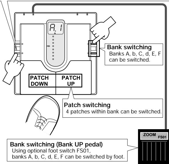
7 Selecting Patches
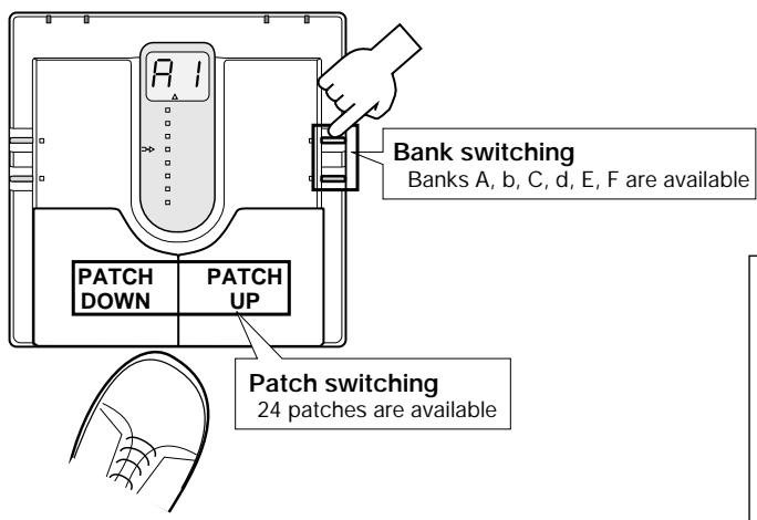
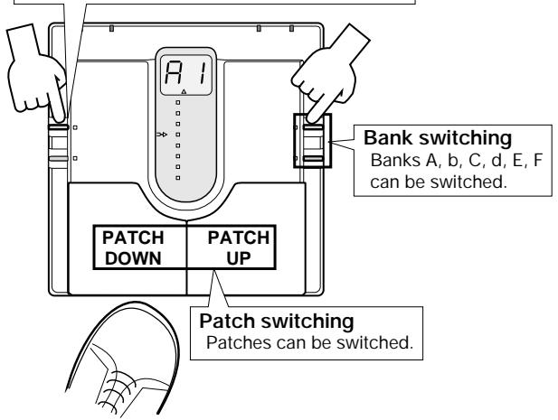
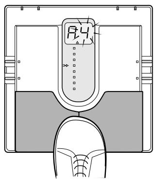
The 24 patches can be selected easily by pressing the patch pedals. The right patch pedal switches to the next patch and the left patch pedal switches to the previous patch.
In the initial condition, the 505 is set up so that the patch pedals select patches continuously, but you can also set up the unit so that patches are switched only within a certain bank [see the section "Patch Switching (Application: Bank Hold)"].
Bank switching is performed with the VALUE + / - keys.
If for example the currently selected patch is patch 2 of bank A, and you want to switch to patch 3 of bank C, you would need to press the UP pedal nine times. Instead, you can press the VALUE + key twice and then the UP pedal once.
If the optional FS01 is connected to the CONTROL IN jack on the rear panel, the foot switch can be used as a bank UP pedal. This allows full foot control, which is highly convenient during a performance.
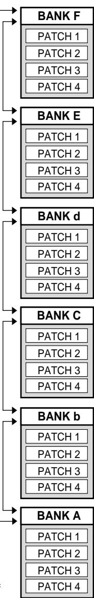
BANK DOWN
Bank/patch switching when Bank Hold is off

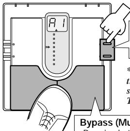
8 Using the Bypass (Mute)/Tuner Mode
In the Bypass mode, the effects of the 505 are temporarily turned off, so that the original sound of the instrument only is heard. In this mode, the auto-chromatic tuning function is also active. It is also possible to activate muting, to prevent the tuning sound from being sent to the output.
Press both
pedals toget
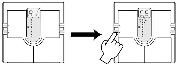
Calibration
Select reference pitch for auto-chromatic
guitar tuning (calibration)
- Reference pitch (A) can be adjusted in the range from 435 to 445Hz . This is shown as "35" to "45" on the display. The normal setting is 440Hz (40).
Bypass and mute condition
Pressing both patch pedals simultaneously activates the Bypass or Mute mode.
- For bypass mode: Press and immediately release the patch pedals.
Currently selected patch is indicated
H
Press
bP
Release immediately
--
Tuner mode
- For mute mode: Press patch pedals for at least 1 second.
Currently selected patch is indicated
H
bP
T
Release
Mute mode
To cancel the bypass or mute condition, simply press one of the patch pedals. The unit then reverts to the previously selected patch.
Tuning function
When the 505 is in the Bypass or Mute mode, the tuning function is activated automatically. Pick an open string to be tuned. The closest note is shown on the display.
Input signal
standby condition


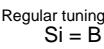

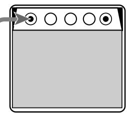
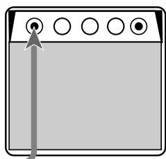
When the tuning function is active, the parameter cursor LEDs serve as tuning meter, designed to enhance tuning precision when making fine adjustments.
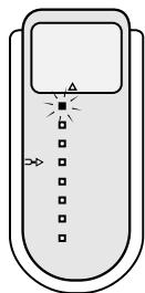
Pitch is too high
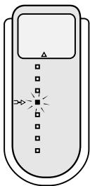
Correctly tuned
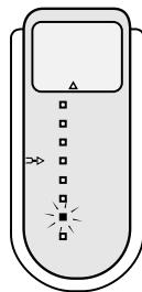
Pitch is too low
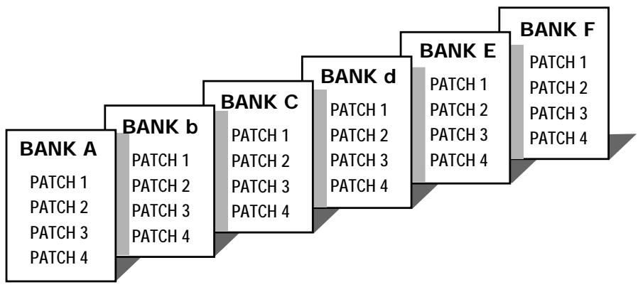
3 What Are Banks and Patches?
- PATCH
A combination of several effects, each with individual parameter settings is called a "patch". The 505 comes with 24 preset patches which can be changed (edited) by the user.
BANK
The 505 calls up patches in sets of four, called a "bank".
4 PATCH LIST
The 505 has memory capacity for 24 patches. At the factory, these are programmed with recommended settings. The user can freely change the contents of any patch, and it is also possible to restore the factory settings.
| BANK | PATCH | PATCH NAME | COMMENT |
| A | 1 | Super Dist Solo | Tight and smooth distortion |
| 2 | Clean Delay | Clean sound with chorus and feedback delay | |
| 3 | Psycho Harmony | Distortion sound for avant-garde harmony solos | |
| 4 | Metal | High-gain metal sound allows 2-octave bend-down with pedal | |
| b | 1 | Mellow Drive | Straight overdrive sound |
| 2 | Wah Dist | Distortion sound with auto wah and chorus | |
| 3 | Multi Phaser | Multi Phaser | |
| 4 | Steel China | Synthesizer-like SFX sound | |
| C | 1 | Rock Drive | Straight rock sound |
| 2 | Bright Chorus | Chorus sound with a distinct edge | |
| 3 | Power Distortion | Distortion with doubling as hidden flavor | |
| 4 | Choir Wave | Clean sound with transparent chorus and flanger | |
| d | 1 | Jet Drive | Wild jet sound with flanger |
| 2 | Funky Phase | Clean sound with wah and effect shift for rhythm play | |
| 3 | Head Long | Zoom's famous step-type effect | |
| 4 | City Night | Clean chorus sound | |
| E | 1 | PWM Synth Lead | Synthesizer sound with full effect palette |
| 2 | JAZZY | Warm jazz sound with octave overlays | |
| 3 | Octave Pitch | Wild and heavy lead sound with up/down octave unison | |
| 4 | Step Mode | SF type sound combining step effect with chorus | |
| F | 1 | Wah Fuzz | Noisy wah/fuzz sound |
| 2 | Blues Lead | Lead sound for fusion and blues | |
| 3 | Blues Rhythm | Cutting sound with distortion as hidden flavor | |
| 4 | Acoustic | Electric acoustic guitar simulation sound |
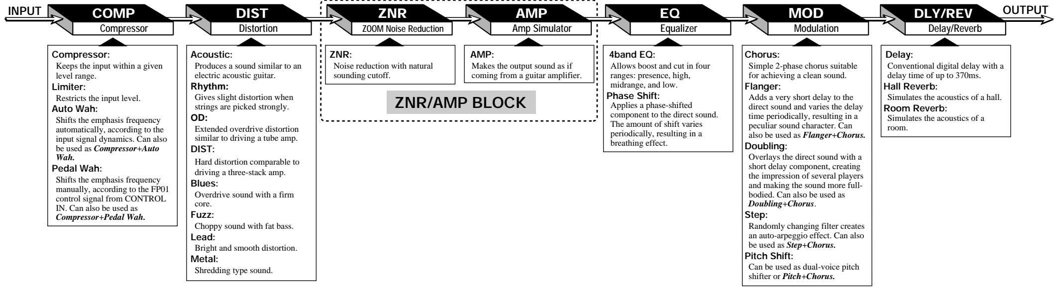
5 Effect Connections
As shown in the illustration below, the 505 can be thought to contain seven "effect modules" which are internally connected. In most effect modules, only one effect may be active at any given time, but the COMP
and MOD modules can use two effects simultaneously. Therefore the 505 can act like a total of nine single effect devices.
6 Controls and Functions
Top Panel
TUNER indicator
In the Bypass (Mute)/Tuner mode, this indicator shows that the tuner is active, and it serves as a gauge for fine tuning your instrument.
- Battery empty warning
When the unit is powered from the battery, this indicator begins to flash when the battery is exhausted.
STORE key
Serves to initiate and execute the store function for patches.
- Direct Load function
When the key is held down for at least 1 second in the Play mode, the Direct Load function is turned on or off.
EDIT key
This key serves to toggle between the Play mode (where effects are used for playing the instrument) and Edit mode (where the user can freely change patch settings). The Edit mode is also used to select effect parameters.
When the key is pressed while a Delay/Reverb effect parameter is selected, the unit switches back to Play mode.
Bank Hold function
When the key is held down for at least 1 second in Play mode, the Bank Hold function is turned on or off.
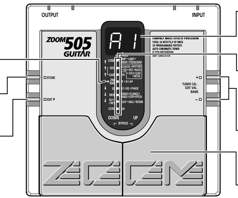
Display
Shows information required to operate the 505.
- Play mode:
Shows the currently selected bank and patch.
- Edit mode:
Shows the value of the parameter currently being edited.
- Bypass (Mute)/Tuner mode:
Shows the pitch of the input signal
Parameter cursor LEDs
- Play mode:
The currently used effect module lights up.
- Edit mode:
The currently used effect module lights up. When selected for editing, the indicator for the effect module flashes.
- Bypass (Mute)/Tuner mode:
Indicators function as tuning meter.
VALUE + / -keys
- Play mode:
The keys serve for bank switching. - Edit mode:
The keys serve for changing the effect parameter. - Bypass (Mute)/Tuner mode:
The keys serve for setting the tuner reference pitch (calibration).
Patch UP / DOWN pedals
- Play mode:
The pedals serve for patch switching. Pressing both pedals simultaneously activates the Bypass (Mute)/Tuner mode. - Edit mode:
The pedals serve for selecting effect parameters. Pressing both pedals simultaneously turns the currently selected effect module on or off. - Bypass (Mute)/Tuner mode:
Pressing a pedal cancels the Bypass (Mute)/Tuner mode.
Rear Panel
INPUT jack
Serves for connection of the guitar.
When the unit is powered from the battery, this jack also functions as on/off switch. Plugging a shielded cable into the jack turns the 505 on. When not using the unit, the cable should be disconnected to prevent battery drain.
DC IN jack
Serves for connection of an AC adapter (Zoom AD-0006) which
delivers 9V DC, 300mA with a "center minus" plug configuration. When the AC adapter is connected to this jack, the 505 is turned on.
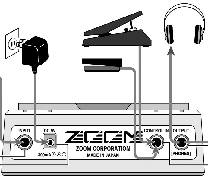
OUTPUT jack
The output signal of the 505 appears at this jack.
You can connect either a single guitar amplifier, using a monaural
shielded cable, or two guitar amplifiers, using a Y-type stereo shielded amplifier.
a cable, or a pair of stereo headphones. If the volume level is low with
using headphones, increase the patch level or master level, or use headphones with low impedance (32 ohms or less).
CONTROL IN jack
When the optional expression pedal FP01 is connected to this jack, it
can serve as volume pedal or be used for pedal wah and pedal pitch.
When the optional foot switch FS01 is connected, it can serve for the following functions:
bank UP switching.
The 505 comes with 24 predefined patches that have been programmed at the factory. However, the 505 offers many more possibilities for combining effects in innovative ways. To discover these possibilities, we recommend that you try out the editing function, which lets you create your own patches. The mode in which patches can be edited is called the Edit mode.
To switch from normal Play mode to Edit mode, briefly press the EDIT key. Do not keep the EDIT key depressed, because if the key is held for 1 second, the Bank Hold mode will be activated.
(1) While still in Play mode, select the patch you wish to edit.
(2) Press the EDIT key to activate the Edit mode.
Immediately after switching from the Play mode to the Edit mode, the parameter cursor flashes at the highest position (COMP module), regardless of which patch was selected. The COMP module setting of the current patch is shown on the display.
While Edit mode is active, each push of the EDIT key causes the parameter cursor to move one position down.
The flashing position shows which module is selected for editing. The relation between parameter cursor LEDs and modules is as shown below.
1st parameter cursor LED: COMP module setting
2nd parameter cursor LED: DIST module distortion type setting
3rd parameter cursor LED: DIST module distortion gain setting
4th parameter cursor LED: ZNR and AMP block settings
5th parameter cursor LEDs: EQ module setting
6th parameter cursor LED: MOD module setting
7th parameter cursor LED: DLY/REV module setting
8th parameter cursor LED: PATCH level setting
Use VALUE + / - keys to change parameters.
For an explanation of the various parameters, please refer to the section "Effect Parameters".
When the EDIT key is pressed while the 8th parameter cursor LED flashes, the Edit mode is canceled and the unit returns to the Play mode.
(1) Use the EDIT key to select the parameter you wish to change.
(2) Use the VALUE + / - keys to adjust the parameter.
(3) When the 8th parameter cursor LED is flashing, press the EDIT key to return to the Play mode.
12 Effect Parameters
COMP module
Compressor
The input signal from the
guitar is compressed to
achieve a uniform v
level.
Setting range: &(C1-C9)
Higher values result in
stronger compression.
Limiter
Limits the input signal with
faster response than the
compressor effect. Serves
prevent overload of other
modules.
Setting range: { } ⇌ { 9(1,1-9) }
Higher values result in more
Higher values are effective limiting
Auto Wah
With this effect, emphasized
frequencies are shifted
automatically depending on
the dynamics of the input
signal.
Setting range: _(A1 - A4)
Higher values result in a
Higher values result in a more pronounced auto wab
effect.
B5<
Compressor and auto web
Compressor and auto wash are used together. Higher
values result in a more
pronounced auto wah effect.
Compressor intensity is
fixed.
Pedal Wah
With this effect, emphasized
frequencies are shifted using
an optional expression
FP01 connected to the
CONTROL IN JACK
Setting range: (P1-P4)
Higher values result in a
higher pedal wah center
frequency.
P
Camprocer and nodal web
Compressor and pedal wan are used together. Higher
are used together. Higher values result in a higher
pedal wah center frequency.
Compressor intensity is
fixed.

1 Selecting parameters to change
#
As described in 'Editing
Patches", parameters to b
edited are selected by repeatedly pressing
the EDIT key, but you can also use the patch

2 Effect module on/off switching
Each effect module in the 505
can be considered as a single
compact effect device. Adjusting parameters
then is equivalent to selecting the type of
effect device or turning the knobs on
effect device. What is called a patch
corresponds to a collection of effect devices
connected in various ways and set to ON or OFF.
As you will know if you have used several
individual effect devices in a performance
before, not all devices will be switched on
all the time. Depending on the mood of the
song and other factors, devices will beswitched on and off in different
combinations. The same applies to the 505.
The on/off timing and combination of effect
modules are important aspects in creating a
certain sound.
Except for the distortion gain (3rd
pedals for this purpose.
Pressing the patch UP pedal (right pedal)
moves the parameter cursor (the selected
parameter) up.
parameter cursor position) and patch level
setting (lowest parameter cursor setting),
the flashing parameter cursor indicates that
the corresponding effect module can be
turned on or off.
The ZNR and AMP modules are turned on
and off together. When wishing to dis
them individually, you must do this by setting the parameters accordingly:
Effect modules can be switched on and off in three ways.
- Using the VALUE + / - keys
When using the VALUE + key to increase the response, replace the setting following
the parameter value, the setting following the maximum value is the "effect off" setting.
The maximum value is the "effect of" setting. Similarly, when using the VALUE/E - key to:
Similarly, when using the ASEE key to decrease the parameter value, the setting
before the minimum value is the "effect off"
setting. When the VALUE ^+ key is pressed once in the "effect off" condition, the effect
Pressing the patch DOWN pedal (left pedal)
moves the parameter cursor (the selected
parameter) down.
is turned on and the minimum value is set.
When the VALUE - key is pressed once in
the "effect off" condition, the effect is turned on and the minimum value is set.
- Using a shortcut
Pressing both VALUE + / - keys together for
an effect module functions as a shortcut.
Repeating the shortcut procedure several
times turns the effect off. Performing the
shortcut when the effect is off turns it on and sets the minimum amount of pixels.
- Using the patch pedals
Pressing both patch pedals together for an
effect module turns the effect off. Pressing
both patch pedals together when the effect is off turns it on and restores the previously.
off turns it on and restores the previously selected parameter value.
Effect offindication
EFFECT OFF=
MOD module
Chorus
Simple 2-phase chorus which
adds a component with periodically changing pitch to
periodically changing pitch to the direct sound. Suitable for
the direct sound. Suitable for enhancing body while
maintaining a clean sound.
Setting range: I _(C1 - C9)
Higher values result in a
Higher values result in a stronger effect
■
Flanger
Adds a very short delay to the
direct sound and varies the
delay time periodically,
resulting in a peculiar sound
C
Can also be used together with the above effects.
th
Setting range: i F (F1-F6)
Higher values result in faster
flanger modulation.
F7\LFG(F7-F9)
Flanger and chorus are used
together. Higher values
result in faster flanger
modulation. Chorus is fixed.
Doubling
Overlays the direct sound with
a short delay component,
creating the impression of
several players and making the
sound more full-bodied.
Can also be used together with the above effects:
th
Setting range: i (d1-d6)
Higher values result in longer
d7\Ld9(d7-d9)
Doubling and chorus are
used together. Higher values
result in longer doubling
delay time. Chorus is fixed.
Step
Randomly changing filter
creates an auto-arpeggio
effect. Can also be used to determine the effect of
together with the chorus
ef
Setting range: (S1-S6)
Higher values result in faster
57\L59 (S7-S9)
Step and chorus are used
together. Higher values
result in faster step speed.
fixed
Pitch Shift
Can be used as dual-voice
a pitch shifter or as a pitch shift
+
1-octave down pitch shift
sound is mixed in. 5 step down horn
5-step down harmony is mixed in
5-step down harmony and
chorus are mixed in.
4 4 step up harmony is
?
P5 4-step up harmony and chorus are mixed in
1-octave up pitch shift
sound is mixed in.
P7 Slight up/down shift sound
is mixed in, for low
fluctuation chorus effect
4-step up/down harmony is mixed in, for dual voice
pitch shift 1-octave up/down pitch
shift sound is mixed in, for
Pd Using FP01 connected to CONTROLIN (in the
CONTROL IN JACK, PITCH CAN be controlled to two
Can be controlled to two octaves down.
P.. Using FP01 connected
CONTROL IN Jack,
harmony can be controlled
DLY/REV module
PATCH Level
Delay
Conventional digital delay with delay of f = 370
with a delay time of up to 370 ms. By monitoring this effect,
his. By monitoring this effectin stereo, you can achieve a
In stereo, you can achieve a ping-pong delay
pingpong delay:
Setting rep: d1←d0(41, d0)
Setting range: (d1 - d9)
Higher values result in longer delay time.
Delay time: Mix and feedback are also
Mix and feedback are also optimized.
Hall Reverb
Simulates the acoustics of a
hall.
Setting range: H I ⇌ H (H1 - H9)
Higher values result in longer
Higher values result in longer reverb time.
Mix setting is also
optimized.
Room Reverb
Simulates the acoustics of a
room
Setting range: I 9 (r1-r9)
Higher values result in longer
Higher values reverb time.
Mix setting is also
optimized.
tch Level
Allows setting the level of individual level.
Individual patches. This is a simple
This setting is stored in a table like the following:
patch like tr parameters
ing range: (1 - 30)
Higher values result in
Higher value higher level.
.

3 Parameter setting shortcut
Normally, parameter values are set by tapping the
VALUE + or VALUE - key once for each increment.
To allow quick operation in effect modules which contain
more than one effect, you can use the shortcut function which
is activated by pressing both VALUE keys simultaneously. For
example, if you are currently at the "Delay" parameter of the DLV/REV module and the current setting is "d5", you would:
BEL/KEV module and the current setting is "a5", you would need to press the VALUE + key 18 times to set the "Room".
need to produce the "MBOX" key to be linked to set the "some effect to "r5". However, you can achieve the same effect by
activating the shortcut twice and then pressing the VALUE +
key

4 Volume control with FPO
When the optional expression pedal EP01 is
connected to the CONTROL IN jack, it can also be
used for adjusting the output volume of the 505. However, if
the COMP module parameter is set to a range which activates
pedal wah or if the MOD module pitch shift parameter is set
to pedal pitch (Pu or Pd), this setting has priority and the pedal controls the effect.
In other cases, the pedal controls the volume between the EQ
module and the MOD module. As opposed to a volume pedal
connected after the 505, the level can be adjusted without affecting the sensory impression of reward and delay effects.

5 Master level adjustment
The 505 also lets you set the overall output level
We use the same set of the original patch separately from individual patch levels.
The master level can be adjusted in Play mode, as follows.
Keep both VALUE keys depressed for at least 1 second . Thewest master key is the key shown in the display for 1 second
current master level is then shown on the asplay for 1 second. While the level is displayed, you can use the VALUE / -/keys
While the level is displayed, you can use the VALUE > < keys to change it. The setting range is 0 - 50. At "40", the level is
identical to the individual patch level.
The master level setting is not stored by the unit. After the
power has been turned off, the master level must be set again.
13 Storing Patches
If you have edited (altered) a patch and turn the 505 off without storing the patch, the patch will revert to its old setting. To store an edited patch, use the following simple procedure.
Storing can be carried out in Play mode and Edit mode. After you have edited the patch, press the STORE key. If the unit is currently in Play mode, release the key before 1 second has elapsed, otherwise the Direct Load function will be activated.
The display starts to flash. This condition is called the store standby condition. If you wish, you can abandon the store procedure at this point by pressing the EDIT key. If you press the STORE key once more, the contents of the patch are updated.
You can also change the patch number before storing, so that the edited patch will be stored in a different number.
In this case, the original patch that was used as a starting point for editing will not be changed.
(2) Press the STORE key.
hters store standby mode.)
(4) Press the STORE key once more.
process is completed.)
(1) Edit the patch as desired.
(3) Select the patch for storing.
14 Replacing the Battery
If the tuning indicator flashes while the unit is being powered from the battery, the battery is exhausted and should be replaced as described below.
Since the 505 has fairly high rated power consumption, use only a 6LR61 9 V (alkaline) battery. Using another kind of battery will result in shorter operation.
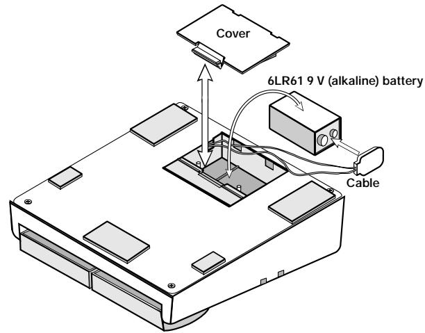
- Turn the 505 upside down and open the cover of the battery compartment. (Push the catch to unlock the cover, then lift it up.)
- Remove the battery from the compartment and disconnect the battery cable. (Grasp the terminal strip and do not pull at the cable.)
- Connect the battery cable to the new battery, taking care to observe correct polarity (+/-) . Then insert the battery into the battery compartment.
- Close the battery compartment cover, taking care not to pinch the cable. (Make sure that the cover is properly locked.)
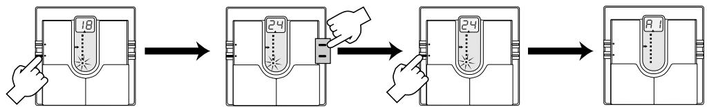
15 Returning Patches to Factory Settings
The 505 comes with 24 predefined patches that have been programmed at the factory. Also after you have edited and stored your own patches, you can return to the factory default settings at any time. This process is called "recalling". Returning all 24 patches to the original contents and resetting the Bank Hold and Direct Load functions is called "all initialize".
The recall mode is separate from the Play mode and Edit mode. You cannot switch directly to recall mode from these modes. The recall mode can only be activated by turning the unit on in a special way, as described below.
- Turn the unit off by disconnecting the AC adapter or the guitar input cable.
- Keep the STORE key depressed and turn the unit on.
- The indication "AL" flashes on the display.
- To perform "all initialize", press the STORE key once more in this condition. The flashing rate increases and the initialization procedure is carried out. When it is completed, the unit automatically enters the Play mode.
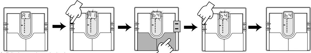
- When wishing to recall only a particular patch, select the patch number in step 3, using the same procedure as for normal patch selection.
- When the desired patch has been selected, press the STORE key. The flashing rate increases and the contents of the selected patch are recalled.
- Recalling of individual patches can be carried out continuously. When you wish to terminate the process, press the EDIT key. The unit then returns to the Play mode. Turning the unit off also terminates the recall condition.
16 Specifications
Effects
Maximum number of simultaneous effects: 9
24 effect types: Compressor, Limiter, Auto Wah, Pedal Wah, Acoustic, Rhythm, Overdrive, Distortion, Blues, Fuzz, Lead, Metal, 4Band Equalizer, Phase, Chorus, Flanger, Doubling, Step, Pitch Shift, Delay, Hall, Room, Amp Simulator, ZNR
Effect modules
Banks and patches
Analog/digital conversion
Digital/analog converge
Sampling frequency
Input
Guitar input (standard monaural phone jack)
Rated input level: -20 dBm
Input impedance: 470 kilohms
Combined line/headphone output (standard stereo phone jack)
Max. output level: +6 dBm
Output load impedance: 10 kilohms or more
Control input
Display indicat
For optional FP01 or FS01
2-digit, 7-segment LED
tuning indicator, parameter cursor indicator
Power requirements
Optional AC adapter: 9V DC, 300mA (Zoom AD-0006)
Battery: 6LR61 9 V (alkaline) battery x 1
Battery life: approx. 4h continuous operation
Dimensions
Weight
480g
-
0 dBm = 0.775 Vrms
-
Design and specifications subject to change without notice.
9 Patch Switching (Application: Bank Hold ON)
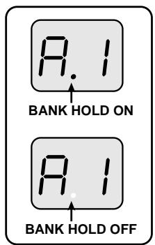
In the factory default condition, the patch pedal switches all patches, regardless of the bank divisions. This kind of patch switching is called the Bank Hold off condition.
The Bank Hold function limits switching to the four patches within a bank. When the function is activated, the patch pedals switch only between the patches in the current bank. To activate the function, keep the EDIT key depressed for at least 1 second in the Play mode. The BANK HOLD indicator on the display lights up. To turn the function off again, perform the same step (press the EDIT key for at least 1 second). The BANK HOLD indicator on the display goes out.
Bank switching can be performed using the VALUE + / - keys or the optional foot switch FS01 connected to the CONTROL IN ja
Keeping the EDIT key depressed for at least 1 second activates Bank Hold. To cancel Bank Hold, press the EDIT key again for 1 second.
Bank Hold ON
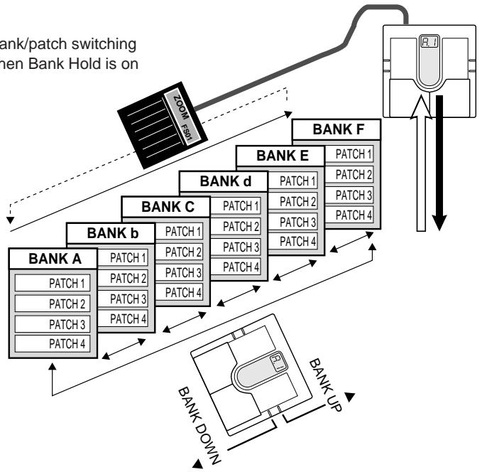
Bank/patch switching when Bank Hold is on
10 Patch Switching (Application: Direct Load OFF)
In the default condition, the 505 is set up in such a way that pressing a patch pedal immediately switches the patch and alters the output sound. This is called Direct Load ON. This switching principle is most convenient when the desired patches are adjacent or close to each other. However, when wanting to switch to a patch that is further away, it may be desirable not to activate the sound of the other patches in between.
When this is desired, turn the Direct Load function off as follows. When Direct Load has been turned off, switching banks and patches has no effect until the user confirms the selection.
Keeping STORE key depressed for 1 second
turns Direct Load off.
The same procedure serves to turn it on.
DIRECT LOAD OFF
For example, when going from patch 1 to patch 4 with Direct Load and 3 will briefly be heard when the is pressed three times. When Direct pressing the patch UP pedal will c on the display (the number flashes) user confirms the choice, the sound patch 1.
To turn Direct Load on or off, keep the STORE key depressed for at least 1 second.
To confirm a choice after selecting a patch with Direct Load off, press both patch pedals simultaneously.
When display indication flashes, pressing both patch pedals together confirms the patch and switches the output sound.
Confirming a patch
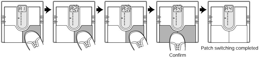
Example: switching from patch 1 to patch 4
- ZOOM CORPORATION
- Major Features
- Safety Precautions
- USAGE AND SAFETY PRECAUTIONS
- About power
- AC adapter operation
- Battery operation
- Environment
- Handling
- Usage precautions
- Electrical interference
- Cleaning
- Connecting cables and input and output jacks
- Selecting Patches
- Using the Bypass (Mute)/Tuner Mode
- Bypass and mute condition
- Tuning function
- What Are Banks and Patches?
- - PATCH
- BANK
- PATCH LIST
- Effect Connections
- Controls and Functions
- Top Panel
- TUNER indicator
- STORE key
- EDIT key
- Display
- Parameter cursor LEDs
- VALUE + / -keys
- Patch UP / DOWN pedals
- Rear Panel
- INPUT jack
- DC IN jack
- OUTPUT jack
- CONTROL IN jack
- Effect Parameters
- COMP module
- Compressor
- Limiter
- Auto Wah
- Pedal Wah
- Selecting parameters to change
- #
- Effect module on/off switching
- MOD module
- Chorus
- Flanger
- Doubling
- Step
- Pitch Shift
- DLY/REV module
- PATCH Level
- Delay
- Hall Reverb
- Room Reverb
- tch Level
- Parameter setting shortcut
- Volume control with FPO
- Master level adjustment
- Storing Patches
- Replacing the Battery
- Returning Patches to Factory Settings
- Specifications
- Patch Switching (Application: Bank Hold ON)
- Patch Switching (Application: Direct Load OFF)
Brand : ZOOM
Model : 505
Category : Guitar Multi-Effects