
PSS-24WRA - Loudspeaker ALPINE - Free user manual and instructions
Find the device manual for free PSS-24WRA ALPINE in PDF.
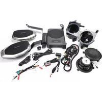


| Product Type | 2-Way Coaxial Loudspeaker |
| Brand | Alpine |
| Model | PSS-24WRA |
| Woofer Size | 4 inches (100 mm) |
| Tweeter Size | 1 inch (25 mm) soft dome |
| Peak Power Handling | 150 watts |
| RMS Power Handling | 50 watts |
| Impedance | 4 ohms |
| Frequency Response | 60 Hz – 20 kHz |
| Sensitivity | 90 dB @ 1W/1m |
| Mounting Depth | 2.5 inches (64 mm) |
| Mounting Diameter | 4.6 inches (117 mm) |
| Magnet Weight | 8 oz (227 g) |
| Voice Coil Diameter | 1.0 inches (25 mm) |
| Cone Material | Polypropylene / Mica composite |
| Tweeter Type | Silk dome with neodymium magnet |
| Crossover Type | Integrated 12 dB/octave |
| Warranty | 1 year limited warranty |
| Cleaning Instructions | Wipe with a soft dry cloth; do not use liquids |
| Safety Warnings | Keep away from moisture and magnetic media |
| Compliance | RoHS compliant |
Frequently Asked Questions - PSS-24WRA ALPINE
User questions about PSS-24WRA ALPINE
0 question about this device. Answer the ones you know or ask your own.
Ask a new question about this device
Download the instructions for your Loudspeaker in PDF format for free! Find your manual PSS-24WRA - ALPINE and take your electronic device back in hand. On this page are published all the documents necessary for the use of your device. PSS-24WRA by ALPINE.
USER MANUAL PSS-24WRA ALPINE
Jeep Wrangler PSS-24WRA
Installation Manual
● Model: Wrangler JL 2018-Up
● Model: Gladiator JT 2020-Up

Jeep
Model Year
Wrangler JL** 2018 – Up
Gladiator JT** 2020 – Up
** The specified vehicles have been tested and have met compatibility specs at the time of testing. Compatibility is not guaranteed if the manufacturer has made production changes to the listed vehicles above.
Introduction
- Congratulations on purchasing the PSS-24WRA. This installation manual is designed to take you through the step-by-step installation of PSS-24WRA into a 2018-Up Jeep Wrangler JL or Jeep Gladiator JT 2020-Up. Please familiarize yourself with the owners manual as this is a challenging installation. If you still have additional questions please call 1-800-TECH-101.
Note
- Design and specifications are subject to change without notice for improvement.
To Ensure Safe Use, Always Follow These Precautions
● The installation of this product requires specialized skills and experience. This is an installation that is challenging and time consuming even for installers with experience. A professional installer would typically take a minimum of 4-5 hours to complete this installation. We recommend that you have the product installed by an Alpine authorized dealer.
- Before you use this product, be sure to carefully read this installation manual and the separate user's manual so that you can use the product correctly. Alpine Electronics bears no responsibility for problems that arise as a result of failure to follow the instructions in the manuals.
- This manual includes a number of symbols that are intended to help you use the product safely, to prevent harm to you and others, and to protect against damage to property. These symbols and their meanings are listed below.
Make sure you fully understand these symbols before you begin reading the main text.
Explanations of Injury and Damage That May Result from Incorrect Use
| [SH2C] Warning | Ignoring the content marked by this indication and using the product incorrectly is expected to lead to death or serious injury. |
 Caution Caution | Ignoring the content marked by this indication and using the product incorrectly is only expected to lead to injury or property damage. |
Types of Precautions
 Forbidden Forbidden | Indicates actions that are forbidden (must not be performed) |
 Forbidden Forbidden | Indicates that disassembly is forbidden. |
 Mandatory Mandatory | Indicates actions that are mandatory (must be performed) |
 | Marks content that should receive your full attention. |
Warning
Do not disassemble or modify the product. Doing so could lead to an accident, fire, or electric shock.
Store screws and other small objects where children cannot reach them. If one of those small objects is swallowed, consult with a doctor immediately.
When replacing fuses be sure to use the fuses with the specified current rating. Failing to do so could lead to an accident or fire.
Only connect the product to a 12 VDC negative ground car. Failing to do so could lead to an accident or fire.
Since this vehicle has two batteries, disconnecting the battery is not a good option. Take caution when testing circuits. Failing to do so could lead to electric shock or injury.
Do not cut the insulation on a cord and take power from another device. Doing so could lead to fire or electric shock.
Do not install the product in a location where it will obstruct the driver's forward view; interfere with the operation of the steering wheel, gear shift, or the like; or pose a threat to passengers. Doing so could lead to an accident or injury.

Forbidden


Mandatory Forbidden


Mandatory


Forbidden

Forbidden
When making a hole in the vehicle body, be careful to avoid damaging pipes, the fuel tank, electrical wiring, and the like. This kind of damage could lead to an accident or fire.
When installing and grounding the product, do not use any of the bolts or nuts of the steering wheel, brakes, fuel tank, or the like. Doing so could make the brakes stop working or could lead to fire.
Do not install the product near the passengerside airbag. Doing so could interfere with the operation of the airbag and lead to an accident or injury.
Bundle cords so that they don't interfere with driving. Wrapping cords around the steering wheel, gearshift, brake pedal, or the like could lead to an accident or damage equipment.


Forbidden

Forbidden

Caution
Connect the product properly according to the instructions. Failing to do so could lead to fire or an accident.
Do not sandwich cords between the seat railing or allow them to touch protrusions. Resulting breaks or shorts could lead to electric shock or fire.
Do not block vents or heat sinks. Doing so could lead to fire or damage equipment.
Use the accessories according to the instructions, and attach them securely. Failing to do so could lead to an accident or damage equipment.
Do not install the product where it may be exposed to water or in a place with high levels of humidity or dust. Doing so could lead to fire or damage equipment.
The installation and wiring of this product requires specialized skills and experience. Have the product installed by an Alpine authorized dealer.

Forbidden


Forbidden

Forbidden

Tools Required
| Wire Strippers | Sockets:7mm, 8mm, 10mm, 13mm | Panel Removal Tools |
 |  |  |
| Wire Cutters Extension Ratchet | ||
 |  |  |
| #2 Phillips Screwdriver Torx T15, T20, T30, T50 5mm Allen Wrench | ||
 |  |  |
| Digital Multimeter Cordless | Power Drill Air saw or similar | |
 |  |  |
| Silicone | ||
 | ||
Accessory List
| Front speaker pods 6.5” Woofers Tweeters | ||||
 |  |  |  |   |
| Amplifier Assembly Tweeter | Adaptors SPV-65-JLT | |||
 |  |  |   | |
| Template Cable Ties (10) Replacement Bolts x 8 | ||||
 |  |  | ||
| Crossovers Bass Control Knob Main Harness | ||||
 |  | 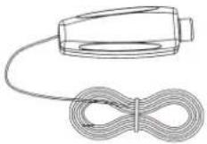 |  | |
| T-Harness Power Cable | RCA Adaptors | |||
 |  |  | ||
| Polyfill Sheets (4) | ||||
 | ||||
Front speaker removal and installation
1 Unclip and remove the panel below the steering column.

3 Unclip the steering column shroud then set aside.

5 Remove the (2) Phillips screws securing the radio trim panel, then unclip and remove.

2 Remove the (2) Phillips screws exposed.

4 Unclip, unplug, and remove the climate control panel.

6 Extract the (4) 7mm, screws from the factory radio, disconnect and remove it.

Front speaker removal and installation (continued)
7 Using a panel removal tool, release the clips on the top dash speaker grilles and remove them.

9 Remove the (4) Phillips screws securing the instrument panel on the left side, unclip and remove panel.

11 Remove the (5) Phillips screws securing the left side dash panel, then unclip and remove.

8 Remove (1) Phillips screw securing the dash pad, then unclip and remove.

10 Remove panel on the left side of the dash then remove the (5) Phillips screws exposed.

12 Remove the (4) screws securing the top of the air bag panel.

Front speaker removal and installation (continued)
13 Remove the (4) 10mm screws and the (1) 8mm screw securing the dashboard brace. The brace only needs loosened to aid in removing the speaker pod in the next step.

14 Remove the (3) Phillips screws securing the speaker pod, then unplug and remove. the pod.

15 There is an electronic module attached to the back of the pod which must be removed and reused in kit assembly.

16 Open the passenger door and remove the panel on the right end of the dash. Remove the (5), Phillips screws exposed.

17 Pry outward in the bolt cover on the right end of the grab bar and remove the (2) 10mm bolts securing it to the dash.

18 Remove the glovebox then remove the (3) Phillips screws exposed.

Front speaker removal and installation (continued)
19 Looking up under the airbag assembly, remove the (2) 13mm, bolts that secure the back of the passenger side airbag.

20 Unclip and slightly release the airbag panel, just enough to expose the (3) Phillips, screws securing the passenger side dash panel.

21 Carefully unclip and pull out on the dashboard panel enough to expose the speaker pod. Remove the (3) Phillips, screws securing the pod and remove.

22 Remove the factory speakers from the speaker pods.

23 Remove the grommet and factory wiring from the speaker pods.

24 Insert the factory wire into the replacement speaker pods and pull gromment thru until it seats into the hole.

Front speaker removal and installation (continued)
25 Insert (1) polyfill sheet into each speaker pod, connect and mount Speakers using factory screws from step 22 then reinstall speaker pods in reverse order and reassemble dash components to their original location.

26 Extract (2) 7mm screws from each of the factory top dash speakers and remove them.

27 Firmly press tweeter into mounting adaptor plate.

28 Connect crossover as shown. Note: it is recommended to use the red (+) lead when utilizing the OEM radio.

29 Connect tweeter to crossover and mount them using the factory screws.

30 Align the factory tweeter grill clips and secure by firmly pressing downward.

Sub Woofer/Amp Installation
1 Extract (4) T50 Torx Screws from the passenger side seat.

3 Connect the power cable to the Positive (+) battery terminal and route the cable down towards frame of the vehicle.

5 Route the Positive (+) power cable through the grommet under the carpet and pull the power cable from under the vehicle. Note: seal the grommet with silicone (not included) to prevent water from entering the cabin.

2 Tilt the passenger seat towards the back to reveal (2) connectors, disconnect and remove the seat.

4 Route the power cable following the factory harness along the vehicle's frame and secure using supplied cable ties.

6 Mount the subwoofer level remote on the center console next to the gear shifter and route the cable to the passenger side seat. Plug 3.5mm plug into the bass knob input of the PWE-S8.

Sub Woofer/Amp Installation (continued)
7 Remove 10mm nut and attach the negative (-) ground terminal to the factory ground stud below the center console.

8 Connect the main harness to the amplifier assembly and align it to the seat mounting holes.

9 Connect the power cable to the main harness.

10 Route the main harness along the side of the center console to the radio location.

11 Connect the T-harness and the radio with either the Tharness or the RCA adaptors. Refer to page 15 and 16 for the correct system diagram. Return all removed components to their original location.

Rear Soundbar Speaker Removal & Installation
1 Extract the (4) 5mm, allen head, bolts and remove factory grills.

3 Remove gromment holding speaker wire in place and secure speaker wire out of the way.

5 With a reciprocating air saw or preferred cutting device, cut along the line from step 4. Note: Be cautious when cutting not to cut thru the topside of the sound bar.

2 Extract the (5) T20, torx, screws from the speakers and the (4) T30, torx, screws from the port and remove.

4 Use supplied template and mark area of each side for soundbar cutting.

6 Fill the speaker cavities with supplied polyfil sheets.

Rear Soundbar Speaker Removal & Installation (continued)
7 Plug in the speaker. Use the supplied replacement bolts (not the OEM 5mm allen heads) and mount the speaker in the bar.

Troubleshooting Guide
| Symptom Possible Cause | Remedy | ||
| 1 System will not turn on Missing or blown fuse at the battery | Insert or replace fuse | ||
| Radio's Remote Turn-On wire may be disconnected. | Verify that Remote Turn-On wire is connected. | ||
| 2 Volume is too loud with aftermarket headunit. | Speaker level out is connected at the T-Harness. | Ensure that the low level RCA adapters are used in aftermarket headunit system (refer to the corresponding wiring diagram). | |
| Amplifiers gain control has not been properly adjusted. | Refer to the corresponding system diagram. | ||
| 3 Subwoofer sounds very low. Gain level may be down to the lowest setting. | Adjust level to recommended setting (refer to the corresponding wiring diagram). | ||
| Audio Phase may be reversed. Ensure that the PHASE is set to 0°. | |||
| RCA adaptor not installed Plug, Orange, RCA adaptor into the connector near the PWE-S8 then plug RCA's into PWE-S8. | |||
| 4 One of the speakers has no sound. Disconnected pin or loose connection. | Check all connections to the speaker, loose pins, disconnected terminals etc.. | ||
| 5 Airbag light is on Failed to disconnect the battery while working on the vehicle. | Disconnect the battery and re-connect after 5 minutes. If problem is not solved, the vehicle will have to be taken to a Jeep dealer. | ||
| 6 System turns on only on radio source | Aftermarket Power Antenna wire is connected to amp | Connect the Remote Turn-On wire (Blue/White) to the Blue wire on the amplifier harness. | |
OEM Head Unit Wiring Diagram
![graph TD A["To Vehicle Connectors"] --> B["Power/Speaker 52-in Black Connector"] B --> C["OEM T-HARNESS ADAPTER"] C --> D["Front Speaker 4-PIN WHITE CONNECTOR"] C --> E["Rear Speakers 4-PIN BLACK CONNECTOR"] C --> F["Blue/White Amp Turn-On"] C --> G["TO OEM HEAD UNIT"] C --> H["Subwoofer Level Remot…](/content/2026/07/1521221/images/6734c4ee58961ed57523f7957e4f2f058a4dedf7f03075dd12c251eaaab3ea10.jpg)
POWER PACK AMPLIFIER KTP-445U SUBWOOFER PW


-S8


PHASE


SUB REM


□ SPIN □ REM POWER MODE
NOTE: FOR BEST PERFORMANCE SET AMPLIFIER AND SUBWOOFER TO RECOMMENDED SETTINGS AS SHOWN ABOVE Black squares indicate position of switches.
Alpine Restyle Head Unit Wiring Diagram
![graph TD A["To OBDII Connector"] --> B["Power/Speaker 52-pin Black Connector"] B --> C["Blue/White Amp Turn-on"] C --> D["Black To Chassis Ground"] C --> E["Red To Battery Cable"] F["To Vehicle's Battery POSITIVE (+) Terminal"] --> G["For a detailed Alpine Restyle head unit wiring diagram refer to i…](/content/2026/07/1521221/images/793f57bfeba8ab2c5b1383075bf299e60ed3618acfadbbc9f70f12081bedb5ac.jpg)
POWER PACK AMPLIFIER KTP-445U

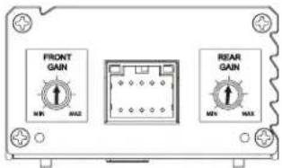
SUBWOOFER PWE-S8

NOTE: FOR BEST PERFORMANCE SET AMPLIFIER AND SUBWOOFER TO RECOMMENDED SETTINGS AS SHOWN ABOVE Black squares indicate position of switches.


- JEEP WRANGLER PSS-24WRA
- INSTALLATION MANUAL
- INTRODUCTION
- NOTE
- TO ENSURE SAFE USE, ALWAYS FOLLOW THESE PRECAUTIONS
- WARNING
- CAUTION
- FRONT SPEAKER REMOVAL AND INSTALLATION
- FRONT SPEAKER REMOVAL AND INSTALLATION (CONTINUED)
- SUB WOOFER/AMP INSTALLATION
- SUB WOOFER/AMP INSTALLATION (CONTINUED)
- REAR SOUNDBAR SPEAKER REMOVAL & INSTALLATION
- REAR SOUNDBAR SPEAKER REMOVAL & INSTALLATION (CONTINUED)
Brand : ALPINE
Model : PSS-24WRA
Category : Loudspeaker